Workshop plan. From zero to results
|
|
|
- August Wilkins
- 10 years ago
- Views:
Transcription
1 Lecture-0 ANSYS in how to start From zero to results 2014 W0-1 Schedule WEiP Workshop plan Week 1 - Quick start in ANSYS Week 2 Geometry DesignModeler (DM) Week 3 Mesh Meshing Week 4 Solver FLUENT/CFX Week 5 - Post Processing Week 6 Import/Export, Data Visualisation Week 7 Exam W0-2

2 ANSYS WEiP Exercise plan Week 1 Steady problems Week 2 Unsteady problems Week 3 Convection Week 4 Turbulent Flows Week 5 Turbomaschinery Week 6 Complex tasks, multiphase flows Week 7 Exam W0-3 Goals WEiP Goals: ANSYS in 45 minutes Workbench Overview Navigate through the GUI viewing controls ANSYS DesignModeler (DM) Overview Draw and dimension a 2-D sketch on the new plane (dimensioning will adequately specify the size and location of the sketch) ANSYS Meshing (AM) Overview Solution- Tutorial #1: 2D plate Post-processing W0-4
 ANSYS Meshing (AM) Overview Solution- Tutorial #1: 2D")
3 Runing ANSYS WEiP Uruchamianie systemu ANSYS Program ANSYS, jako dość wszechstronne i złożone narzędzie, może pracować w różnych trybach, począwszy od trybu wsadowego, poprzez różne interfejsy graficzne, a skończywszy na najbardziej rozbudowanym interfejsie graficznym ANSYS Workbench, umożliwiającym modelowanie złożonych struktur przestrzennych w środowisku przypominającym systemy CAD Poniżej omówiony zostanie standardowy tryb pracy interaktywnej dostępny w każdej instalacji i konfiguracji ANSYSa Warto w tym miejscu nadmienić, że w zaawansowanych zastosowaniach dość przydatny jest również na pozór przestarzały już tryb wsadowy We are going tu work in most advanced ANSYS Workbench W0-5 ANSYS Workbench What is Workbench? WEiP Platform for integration of all ANSYS analysis tools Solid mechanics, fluid dynamics, EM, optimization, etc Entire project contained in common platform: geometry creation, meshing, analysis, and post-processing W0-6

4 Starting Workbench WEiP To start Workbench - Double click on ANSYS Workbench 15 icon W0-7 Workbench Overview WEiP W0-8

5 The Workbench Graphical User Interface WEiP Geometry under component systems This will create a Geometry component in the Project Schematic area W0-9 DesignModeler (DM) Overview WEiP W0-10
")
6 Launching DM WEiP Right click on and select Import Geometry >Browse, and select link1agdb from the list Double click on and DesignModeler will be launched W0-11 DesignModeler (DM) Overview WEiP W0-12
")
7 Mesh WEiP Next task to geometry is mesh W0-13 What is the ANSYS Meshing Application? WEiP ANSYS has been working to integrate best in class technologies from several sources: ICEM CFD TGrid GAMBIT CFX ANSYS Prep/Post Etc W0-14

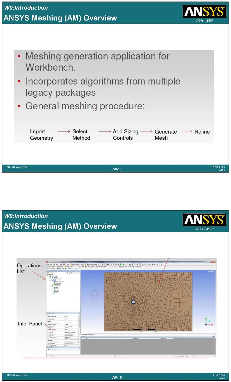
8 ANSYS Meshing Application Overview WEiP The objective of the ANSYS Meshing Application in Workbench is to provide access to common ANSYS Inc meshing tools in a single location, for use by any analysis type: FEA Simulations Mechanical Dynamics Simulation Explicit Dynamics Simulation AUTODYN ANSYS LS DYNA Electromagnetic Simulation CFD Simulation ANSYS CFX ANSYS FLUENT W0-15 Mesh Specification Purpose WEiP For both CFD (fluid) and FEA (solid) modelling, the software performs the computations at a range of discrete locations within the domain The purpose of meshing is to decompose the solution domain into an appropriate number of locations for an accurate result The basic building-blocks for a 3D mesh are: Tetrahedrons (unstructured) Hexahedrons (usually structured) Pyramids (where tet and hex cells meet) Prisms (formed when a tet mesh is extruded) Manifold Example: Outer casting and internal flow region are meshed for coupled thermal/stress gas flow simulation W0-16
 Hexahedrons (usually structured)")
9 ANSYS Meshing (AM) Overview WEiP W0-17 ANSYS Meshing (AM) Overview WEiP W0-18
10 WEiP W0-19 Different Mesh Methods WEiP W0-20

11 Fluent/Setup WEiP Next tasks are Setup and SOLUTION W0-21 How Does CFD Work? ANSYS CFD solvers are based on the finite volume method Domain is discretized into a finite set of control volumes General conservation (transport) equations for mass, momentum, energy, species, etc are solved on this set of control volumes Control Volume* WEiP Fluid region of pipe flow is discretized into a finite set of control volumes Unsteady Convection Diffusion Generation Partial differential equations are discretized into a system of algebraic equations All algebraic equations are then solved numerically to render the solution field * FLUENT control volumes are cell-centered (ie they correspond directly with the mesh) while CFX control volumes are node-centered W0-22 Equation Variable Continuity 1 X momentum u Y momentum v Z momentum w Energy h

12 CFD Modeling Overview Problem Identification 1 Define goals WEiP Problem Identification 1 Define your modeling goals 2 Identify the domain you will model 2 Identify domain Pre-Processing 3 Geometry 4 Mesh 5 Physics 6 Solver Settings Solve 7 Compute solution Post Processing 8 Examine results 9 Update Model PreProcessing and Solver Execution 3 Create a solid model to represent the domain 4 Design and create the mesh (grid) 5 Set up the physics (physical models, material properties, domain properties, boundary conditions, ) 6 Define solver settings (numerical schemes, convergence controls, ) 7 Compute and monitor the solution Post-Processing 8 Examine the results 9 Consider revisions to the model W0-23 SOLVER Parallel processing can be used to run FLUENT on multiple processors to decrease turnaround time and increase simulation efficiency Critical for cases involving large meshes and/or complex physics FLUENT is fully parallelized and capable of running across most hardware and software configurations, such as compute clusters or multi-processor machines Parallel FLUENT can be launched either using the system command prompt or using the FLUENT Launcher panel For example, to launch an n-cpu parallel session, use the command fluent 3d tn The mesh can be partitioned either manually or automatically using a number of different methods Non-conformal meshes, sliding mesh interfaces and shell conduction zones require partitioning in serial A web-based lecture is available on the FLUENT User Services Center WEiP W0-24

13 FLUENT 12 GUI Navigation WEiP The FLUENT GUI is arranged such that the tasks are generally arranged from top to bottom in the project setup tree Selecting an item in the tree opens the relevant input items in the center pane General Models Materials Boundary Conditions Solver Settings Initialization and Calculation Postprocessing W0-25 Scaling the Mesh and Selecting Units When FLUENT reads a mesh file (msh), all physical dimensions are assumed to be in units of meters If your model was not built in meters, then it must be scaled Verify that the Domain Extents are correct after scaling the mesh WEiP When importing a mesh under Workbench, the mesh does not need to be scaled; however, the units are set to the default MKS system Define Units Any mixed units system can be used if desired By default, FLUENT uses the SI system of units (specifically, MKS system) Any units can be specified in the Set Units panel, accessed from the top menu W0-26

14 Material Properties FLUENT provides a standard database of materials and the ability to create a custom user-defined database WEiP Your choice of physical models may require multiple materials and dictate which material properties must be defined Multiphase (multiple materials) Combustion (multiple species) Heat transfer (thermal conductivity) Radiation (emissivity and absorptivity) Material properties can be directly customized as function of temperature/pressure Use of other solution variable(s) requires UDF W0-27 Operating Conditions WEiP The Operating Pressure with a Reference Pressure Location sets the reference value that is used in computing gauge pressures The Operating Temperature sets the reference temperature (used when computing buoyancy forces Specified Operating Density sets the reference value for flows with widely varying density W0-28

15 Changing Boundary Condition Types WEiP Zones and zone types are initially defined in the preprocessing phase To change the boundary condition type for a zone: Choose the zone name in the Zone list Select the type you wish to change it to in the Type pulldown list W0-29 Setting Boundary Condition Data WEiP Explicitly assign data in BC panels To set boundary conditions for particular zone: Select Boundary Conditions in the project tree Choose the boundary name in the Zone list Click the Edit button Boundary condition data can be copied from one zone to another Boundary conditions can also be defined by UDFs and profiles Profiles can be generated by: Writing a profile from another CFD simulation Creating an appropriately formatted text file with boundary condition data W0-30

16 Velocity Inlet Velocity Specification Method Magnitude, Normal to Boundary Components Magnitude and Direction WEiP Applies a uniform velocity profile at the boundary, unless UDF or profile is used Velocity inlets are intended for use in incompressible flows and are not recommended for compressible flows Velocity Magnitude input can be negative, implying that you can prescribe the exit velocity W0-31 Wall Boundary Conditions WEiP Five thermal conditions Heat Flux Temperature Convection simulates an external convection environment which is not modeled (user-prescribed heat transfer coefficient) Radiation simulates an external radiation environment which is not modeled (user-prescribed external emissivity and radiation temperature) Mixed Combination of Convection and Radiation boundary conditions Wall material and thickness can be defined for 1D or shell conduction calculations heat transfer calculations W0-32
 Radiation simulates an external radiation environment which is not modeled (user-prescribed external emissivity and radiation temperature) Mixed Combination of Convection and Radiation")
17 Problem Setup Heat Source WEiP An energy (heat) source is added to the solid zone to simulate the heat generation by the heat-generating electronic components W0-33 Temperature Distribution (Front and Top View) WEiP Temp (ºF) 426 Flow direction Air (fluid zone) Front View Convection boundary 15 W/m 2 K 298 K free stream temp Flow direction Board (solid zone) Elect Component (solid zone) 2 Watts source Top View (image mirrored about symmetry plane) Convection Boundary 15 W/m 2 K 298 K free stream temp W0-34
 2 Watts source Top View (image mirrored about symmetry plane) Convection Boundary 15 W/m 2 K 298 K free stream")
18 Convergence Monitors Residuals WEiP Residual plots show when the residual values have reached the specified tolerance All equations converged W0-35 Results WEiP NOW We are going to the last step RESULTS W0-36

19 Starting CFD-Post WEiP Within ANSYS Workbench Drag the CFD-Post icon in the Component Systems list to the project tree OR, create a standalone CFD-Post session From the Start Menu or Command Line Start > Programs > ANSYS 120 > ANSYS CFD-Post CFD-Post can also be started from the CFX-Solver Manager or the CFX Launcher W0-37 GUI Layout WEiP Additional tabs (various tools) Outline tab ( model tree ) Details view Various Viewers (3D, Chart, ) W0-38
 Outline tab ( model tree ) Details view Various Viewers (3D,")
20 CFD-Post General Workflow WEiP 1 Prepare locations where data will be extracted from or plots generated 2 Create variables/expressions which will be used to extract data (if necessary) 3 i) Generate qualitative data at locations ii) Generate quantitative data at locations 4 Generate Reports W0-39 Creating Locations WEiP Locations are created from the Insert menu or from the toolbar Once created, all Locations appear as entries in the Outline tree Use the check boxes next to each object in the Outline tree to quickly control visibility Double-click objects in the Outline tree to edit Right-click objects in the Outline tree to Duplicate or Delete W0-40

21 Location Types WEiP Planes XY Plane, Point and Normal, etc Can define a circle or rectangle to bound the plane, otherwise it s bounded only by the solution domain(s) Point XYZ: At coordinates Can pick from Viewer Node Number: Some solver error messages give a node number Variable Max / Min: Useful to locate where max / min values occur Point Cloud Create multiple points Usually used as seeds to streamlines, vectors W0-41 Location Types WEiP Lines Straight line between two points Usually used as the basis for an XY Chart Polylines Also used for Charts Read points from a file Use the line of intersection between a boundary and another location Extract a line from a contour plot W0-42
22 Location Types WEiP Volumes Elements are either in or out No cut volumes From Surface A volume is formed from all elements touching (or above / below) the selected location Can be useful for mesh checking Isovolume Base on a variable at, above or below a given value, or between two values W0-43 Location Types Isosurfaces Surface of a variable at a specified value WEiP Isosurface of pressure behind a flap valve Iso Clip An Iso Clip takes a copy of any existing location and then clips it using one or more criteria Eg a outlet boundary plot which is then clipped by Velocity >= 10 [m/s] and Velocity <= 20 [m/s] Can clip using any variable, including geometric variables W0-44
23 Other Tools Timestep Selector Transient results are post-processed by loading in the end results file, then selecting different timesteps from the Timestep Selector WEiP Timestep Animation Quick Probe Selector Editor Animation Animate objects, create MPEGs More on next slide Quick Editor Provides a very quick way to change the primary value associated with each object Probe Pick a point from the Viewer and probe a variable value at that point W0-45 Case Comparison WEiP When multiple files are loaded you can select Case Comparison from the Outline tree Automatically generates difference variables and plots SST k-e Difference Plot Expression syntax: function()@case:#location Eg: areaave(pressure)@case:1inlet W0-46
24 Files Results ANSYS CFD Post can read ANSYS results for temperature, velocity, acceleration, magnetic forces, stress, strain, and mesh deformation WEiP Import Locations csv files which contain point data which defines a polyline or surface ANSYS Surface Mesh (cdb): To allow for export of data on a surface for use as a boundary condition in ANSYS Export Profile Boundary Data: for use in CFX-Pre General formatted results data ANSYS Load Data: Written onto an imported ANSYS cdb file W0-47
ME6130 An introduction to CFD 1-1
 ME6130 An introduction to CFD 1-1 What is CFD? Computational fluid dynamics (CFD) is the science of predicting fluid flow, heat and mass transfer, chemical reactions, and related phenomena by solving numerically
Customer Training Material. Lecture 2. Introduction to. Methodology ANSYS FLUENT. ANSYS, Inc. Proprietary 2010 ANSYS, Inc. All rights reserved.
 Lecture 2 Introduction to CFD Methodology Introduction to ANSYS FLUENT L2-1 What is CFD? Computational Fluid Dynamics (CFD) is the science of predicting fluid flow, heat and mass transfer, chemical reactions,
Introduction to CFD Analysis
 Introduction to CFD Analysis Introductory FLUENT Training 2006 ANSYS, Inc. All rights reserved. 2006 ANSYS, Inc. All rights reserved. 2-2 What is CFD? Computational fluid dynamics (CFD) is the science
Introduction to ANSYS
 Lecture 3 Introduction to ANSYS Meshing 14. 5 Release Introduction to ANSYS Meshing 2012 ANSYS, Inc. March 27, 2014 1 Release 14.5 Introduction to ANSYS Meshing What you will learn from this presentation
Introduction to CFD Analysis
 Introduction to CFD Analysis 2-1 What is CFD? Computational Fluid Dynamics (CFD) is the science of predicting fluid flow, heat and mass transfer, chemical reactions, and related phenomena by solving numerically
Tutorial 1. Introduction to Using ANSYS FLUENT in ANSYS Workbench: Fluid Flow and Heat Transfer in a Mixing Elbow
 Tutorial 1. Introduction to Using ANSYS FLUENT in ANSYS Workbench: Fluid Flow and Heat Transfer in a Mixing Elbow Introduction This tutorial illustrates using ANSYS Workbench to set up and solve a three-dimensional
Express Introductory Training in ANSYS Fluent Lecture 1 Introduction to the CFD Methodology
 Express Introductory Training in ANSYS Fluent Lecture 1 Introduction to the CFD Methodology Dimitrios Sofialidis Technical Manager, SimTec Ltd. Mechanical Engineer, PhD PRACE Autumn School 2013 - Industry
Steady Flow: Laminar and Turbulent in an S-Bend
 STAR-CCM+ User Guide 6663 Steady Flow: Laminar and Turbulent in an S-Bend This tutorial demonstrates the flow of an incompressible gas through an s-bend of constant diameter (2 cm), for both laminar and
Tutorial for laboratory project #2 Using ANSYS Workbench. For Double Pipe Heat Exchanger
 Tutorial for laboratory project #2 Using ANSYS Workbench For Double Pipe Heat Exchanger 1. Preparing ANSYS Workbench Go to Start Menu/All Programs/Simulation/ANSYS 12.1/Workbench. In the toolbox menu in
Essay 5 Tutorial for a Three-Dimensional Heat Conduction Problem Using ANSYS Workbench
 Essay 5 Tutorial for a Three-Dimensional Heat Conduction Problem Using ANSYS Workbench 5.1 Introduction The problem selected to illustrate the use of ANSYS software for a three-dimensional steadystate
TWO-DIMENSIONAL FINITE ELEMENT ANALYSIS OF FORCED CONVECTION FLOW AND HEAT TRANSFER IN A LAMINAR CHANNEL FLOW
 TWO-DIMENSIONAL FINITE ELEMENT ANALYSIS OF FORCED CONVECTION FLOW AND HEAT TRANSFER IN A LAMINAR CHANNEL FLOW Rajesh Khatri 1, 1 M.Tech Scholar, Department of Mechanical Engineering, S.A.T.I., vidisha
Learning Module 4 - Thermal Fluid Analysis Note: LM4 is still in progress. This version contains only 3 tutorials.
 Learning Module 4 - Thermal Fluid Analysis Note: LM4 is still in progress. This version contains only 3 tutorials. Attachment C1. SolidWorks-Specific FEM Tutorial 1... 2 Attachment C2. SolidWorks-Specific
Multiphase Flow - Appendices
 Discovery Laboratory Multiphase Flow - Appendices 1. Creating a Mesh 1.1. What is a geometry? The geometry used in a CFD simulation defines the problem domain and boundaries; it is the area (2D) or volume
Set up and solve a transient problem using the pressure-based solver and VOF model.
 Tutorial 18. Using the VOF Model This tutorial was run using ANSYS FLUENT 12.1. The results have been updated to reflect the change in the default setting of node-based smoothing for the surface tension
ANSYS CFD-Post Standalone: Tutorials
 ANSYS CFD-Post Standalone: Tutorials ANSYS, Inc. Release 12.1 Southpointe November 2009 275 Technology Drive ANSYS, Inc. is Canonsburg, PA 15317 certified to ISO [email protected] 9001:2008. http://www.ansys.com
GAMBIT Demo Tutorial
 GAMBIT Demo Tutorial Wake of a Cylinder. 1.1 Problem Description The problem to be considered is schematically in fig. 1. We consider flow across a cylinder and look at the wake behind the cylinder. Air
ANSYS ICEM CFD - pre-processing program used to generate the geometry and mesh for our CFD simulations.
 Lab 6: Laminar Pipe Flow with Convection Objective: The objective of this laboratory is to introduce you to ANSYS ICEM CFD and ANSYS FLUENT by using them to solve for velocity and temperature profiles
ANSYS CFD-Post Tutorials
 ANSYS CFD-Post Tutorials ANSYS, Inc. Southpointe 275 Technology Drive Canonsburg, PA 15317 [email protected] http://www.ansys.com (T) 724-746-3304 (F) 724-514-9494 Release 15.0 November 2013 ANSYS, Inc.
Lecture 6 - Boundary Conditions. Applied Computational Fluid Dynamics
 Lecture 6 - Boundary Conditions Applied Computational Fluid Dynamics Instructor: André Bakker http://www.bakker.org André Bakker (2002-2006) Fluent Inc. (2002) 1 Outline Overview. Inlet and outlet boundaries.
CCTech TM. ICEM-CFD & FLUENT Software Training. Course Brochure. Simulation is The Future
 . CCTech TM Simulation is The Future ICEM-CFD & FLUENT Software Training Course Brochure About. CCTech Established in 2006 by alumni of IIT Bombay. Our motive is to establish a knowledge centric organization
OpenFOAM Opensource and CFD
 OpenFOAM Opensource and CFD Andrew King Department of Mechanical Engineering Curtin University Outline What is Opensource Software OpenFOAM Overview Utilities, Libraries and Solvers Data Formats The CFD
Trace Layer Import for Printed Circuit Boards Under Icepak
 Tutorial 13. Trace Layer Import for Printed Circuit Boards Under Icepak Introduction: A printed circuit board (PCB) is generally a multi-layered board made of dielectric material and several layers of
Harvesting-Combine-Flow Simulation Technique
 Page 1/14 Madhur Bhaiya, Prof. Dr.-Ing. Andreas Jahr, B.Eng. Holger Happel FH Düsseldorf 1 ABSTRACT CFX 11.0 is a Computational Fluid Dynamics (CFD) program for simulating the behavior of systems involving
Introduction to ANSYS ICEM CFD
 Workshop 8.2 3D Pipe Junction 14.5 Release Introduction to ANSYS ICEM CFD 2012 ANSYS, Inc. April 1, 2013 1 Release 14.5 3D Pipe Junction 3D Pipe Junction This is a simple 4-way pipe intersection with two
Titelmasterformat durch Klicken bearbeiten
 Titelmasterformat durch Klicken bearbeiten ANSYS AIM Product simulation for every engineer Erke Wang CADFEM GmbH Georg Scheuerer ANSYS Germany GmbH Christof Gebhardt CADFEM GmbH All products involve multiple
CFD SIMULATION OF SDHW STORAGE TANK WITH AND WITHOUT HEATER
 International Journal of Advancements in Research & Technology, Volume 1, Issue2, July-2012 1 CFD SIMULATION OF SDHW STORAGE TANK WITH AND WITHOUT HEATER ABSTRACT (1) Mr. Mainak Bhaumik M.E. (Thermal Engg.)
Aerodynamic Department Institute of Aviation. Adam Dziubiński CFD group FLUENT
 Adam Dziubiński CFD group IoA FLUENT Content Fluent CFD software 1. Short description of main features of Fluent 2. Examples of usage in CESAR Analysis of flow around an airfoil with a flap: VZLU + ILL4xx
ANSYS FLUENT. Using Moving Reference Frames and Sliding Meshes WS5-1. Customer Training Material
 Workshop 5 Using Moving Reference Frames and Sliding Meshes Introduction to ANSYS FLUENT WS5-1 Introduction [1] Several solution strategies exist when there are moving parts in the domain. This workshop
This tutorial provides a recipe for simulating L
 Pipe Flow Tutorial for STAR-CCM+ ME 448/548 February 5, 2014 Gerald Recktenwald [email protected] 1 Overview This tutorial provides a recipe for simulating laminar flow in a pipe with STAR- L CCM+. The
Introductory FLUENT Training
 Chapter 10 Transient Flow Modeling Introductory FLUENT Training www.ptecgroup.ir 10-1 Motivation Nearly all flows in nature are transient! Steady-state assumption is possible if we: Ignore transient fluctuations
CastNet: Modelling platform for open source solver technology
 CastNet: Modelling platform for open source solver technology. DHCAE Tools GmbH Address: Friedrich-Ebert-Str. 368, 47800 Krefeld, Germany / Company site: Alte Rather Str. 207 / 47802 Krefeld Phone +49
Customer Training Material. Lecture 4. Meshing in Mechanical. Mechanical. ANSYS, Inc. Proprietary 2010 ANSYS, Inc. All rights reserved.
 Lecture 4 Meshing in Mechanical Introduction to ANSYS Mechanical L4-1 Chapter Overview In this chapter controlling meshing operations is described. Topics: A. Global Meshing Controls B. Local Meshing Controls
CFD software overview comparison, limitations and user interfaces
 CFD software overview comparison, limitations and user interfaces Daniel Legendre Introduction to CFD Turku, 05.05.2015 Åbo Akademi University Thermal and Flow Engineering Laboratory 05.05.2015 1 Some
Heat Transfer by Free Convection
 Heat Transfer by Free Convection Introduction This example describes a fluid flow problem with heat transfer in the fluid. An array of heating tubes is submerged in a vessel with fluid flow entering at
version 3.0 tutorial - Turbulent mixing in a T-junction with CFDSTUDY in SALOME contact: [email protected]
 EDF R&D Fluid Dynamics, Power Generation and Environment Department Single Phase Thermal-Hydraulics Group 6, quai Watier F-78401 Chatou Cedex Tel: 33 1 30 87 75 40 Fax: 33 1 30 87 79 16 MAY 2013 documentation
Turbulence Modeling in CFD Simulation of Intake Manifold for a 4 Cylinder Engine
 HEFAT2012 9 th International Conference on Heat Transfer, Fluid Mechanics and Thermodynamics 16 18 July 2012 Malta Turbulence Modeling in CFD Simulation of Intake Manifold for a 4 Cylinder Engine Dr MK
ANSYS Example: Transient Thermal Analysis of a Pipe Support Bracket
 ME 477 Transient Thermal Example 1 ANSYS Example: Transient Thermal Analysis of a Pipe Support Bracket The section of pipe shown below is a representative section of a longer pipe carrying a hot fluid
ANSYS Meshing User's Guide
 ANSYS Meshing User's Guide ANSYS, Inc. Southpointe 275 Technology Drive Canonsburg, PA 15317 [email protected] http://www.ansys.com (T) 724-746-3304 (F) 724-514-9494 Release 13.0 November 2010 ANSYS,
Getting Started with ANSYS ANSYS Workbench Environment
 Getting Started with ANSYS ANSYS Workbench Environment Overview The purpose of this tutorial is to get you started with the ANSYS Workbench environment. We will use a simple, static analysis of a single
Customer Training Material. ANSYS Mechanical Basics. Mechanical. ANSYS, Inc. Proprietary 2010 ANSYS, Inc. All rights reserved. WS2.
 Workshop 2.1 ANSYS Mechanical Basics Introduction to ANSYS Mechanical WS2.1-1 Notes on Workshop 2.1 The first workshop is extensively documented. As this course progresses, students will become more familiar
Open Source CFD Solver - OpenFOAM
 Open Source CFD Solver - OpenFOAM Wang Junhong (HPC, Computer Centre) 1. INTRODUCTION The OpenFOAM (Open Field Operation and Manipulation) Computational Fluid Dynamics (CFD) Toolbox is a free, open source
CHEG 3128 Heat, Mass, & Kinetics Laboratory Diffusion in Laminar Flow Regimes Modeling and COMSOL Tutorial Tutorial by Andrea Kadilak
 CHEG 3128 Heat, Mass, & Kinetics Laboratory Diffusion in Laminar Flow Regimes Modeling and COMSOL Tutorial Tutorial by Andrea Kadilak Introduction COMSOL is a computer modeling software package that will
THE CFD SIMULATION OF THE FLOW AROUND THE AIRCRAFT USING OPENFOAM AND ANSA
 THE CFD SIMULATION OF THE FLOW AROUND THE AIRCRAFT USING OPENFOAM AND ANSA Adam Kosík Evektor s.r.o., Czech Republic KEYWORDS CFD simulation, mesh generation, OpenFOAM, ANSA ABSTRACT In this paper we describe
CONCEPT-II. Overview of demo examples
 CONCEPT-II CONCEPT-II is a frequency domain method of moment (MoM) code, under development at the Institute of Electromagnetic Theory at the Technische Universität Hamburg-Harburg (www.tet.tuhh.de). Overview
Simulation of Fluid-Structure Interactions in Aeronautical Applications
 Simulation of Fluid-Structure Interactions in Aeronautical Applications Martin Kuntz Jorge Carregal Ferreira ANSYS Germany D-83624 Otterfing [email protected] December 2003 3 rd FENET Annual Industry
2.1 CFD PROJECT PLANNING. 2006 ANSYS, Inc. All rights reserved. ANSYS, Inc. Proprietary
 2.1 CFD PROJECT PLANNING 2006 ANSYS, Inc. All rights reserved. 2008 ANSYS, Inc. All rights reserved. 6-2 CFD PROJECT PLANNING Task definition Resources Timing and deliverables Design review Assumed part
CFD Summary... 1. Workshop 01 - Basic viewing controls in ANSYS ICEM CFD 13.0
 ANSYS ICEM CFD and ANSYS CFX Introductory Training Course Course notes prepared by David Ryan and updated by Julia Hofinger Acknowledgements to Andrea Gabriele, Dr Hassan Hemida and Muhammad Eesa. CFD
2013 Code_Saturne User Group Meeting. EDF R&D Chatou, France. 9 th April 2013
 2013 Code_Saturne User Group Meeting EDF R&D Chatou, France 9 th April 2013 Thermal Comfort in Train Passenger Cars Contact For further information please contact: Brian ANGEL Director RENUDA France [email protected]
Introduction to COMSOL. The Navier-Stokes Equations
 Flow Between Parallel Plates Modified from the COMSOL ChE Library module rev 10/13/08 Modified by Robert P. Hesketh, Chemical Engineering, Rowan University Fall 2008 Introduction to COMSOL The following
Best Practices Workshop: Heat Transfer
 Best Practices Workshop: Heat Transfer Overview This workshop will have a mixed format: we will work through a typical CHT problem in STAR-CCM+, stopping periodically to elucidate best practices or demonstrate
Advanced discretisation techniques (a collection of first and second order schemes); Innovative algorithms and robust solvers for fast convergence.
; Innovative algorithms and robust solvers for fast convergence.") New generation CFD Software APUS-CFD APUS-CFD is a fully interactive Arbitrary Polyhedral Unstructured Solver. APUS-CFD is a new generation of CFD software for modelling fluid flow and heat transfer in
New generation CFD Software APUS-CFD APUS-CFD is a fully interactive Arbitrary Polyhedral Unstructured Solver. APUS-CFD is a new generation of CFD software for modelling fluid flow and heat transfer in
Embankment Consolidation
 Embankment Consolidation 36-1 Embankment Consolidation In this tutorial, RS2 is used for a coupled analysis of a road embankment subject to loading from typical daily traffic. Model Start the RS2 9.0 Model
Technology Update: Workbench, Geometry, Meshing, Workflow. ANSYS Users Group Meeting Prague, 2011
 Technology Update: Workbench, Geometry, Meshing, Workflow ANSYS Users Group Meeting Prague, 2011 1 Andreas Kolms Hannover 2 Agenda Workbench Geometry Meshing Workflow 3 The Path to Robust Design Optimization
O.F.Wind Wind Site Assessment Simulation in complex terrain based on OpenFOAM. Darmstadt, 27.06.2012
 O.F.Wind Wind Site Assessment Simulation in complex terrain based on OpenFOAM Darmstadt, 27.06.2012 Michael Ehlen IB Fischer CFD+engineering GmbH Lipowskystr. 12 81373 München Tel. 089/74118743 Fax 089/74118749
Tips and Tricks: Design Modeler & ANSYS Meshing
 Tips and Tricks: Design Modeler & ANSYS Meshing 1 June 13th 2013 Andy Wade [email protected] Agenda: This presentation will highlight several common challenges for preprocessing, and provide best practices
Tutorial: 3D Pipe Junction Using Hexa Meshing
 Tutorial: 3D Pipe Junction Using Hexa Meshing Introduction In this tutorial, you will generate a mesh for a three-dimensional pipe junction. After checking the quality of the first mesh, you will create
CastNet: GUI environment for OpenFOAM
 CastNet: GUI environment for OpenFOAM CastNet is a preprocessing system and job-control system for OpenFOAM. CastNet works with the standard OpenFOAM releases provided by ESI Group as well as ports for
Laminar Flow in a Baffled Stirred Mixer
 Laminar Flow in a Baffled Stirred Mixer Introduction This exercise exemplifies the use of the rotating machinery feature in the CFD Module. The Rotating Machinery interface allows you to model moving rotating
External bluff-body flow-cfd simulation using ANSYS Fluent
 External bluff-body flow-cfd simulation using ANSYS Fluent External flow over a bluff body is complex, three-dimensional, and vortical. It is massively separated and it exhibits vortex shedding. Thus,
Contents. First Steps - Ball Valve Design
 Sol i dwor ksfl ow Si mul at i on 2009 Tut or i al Contents First Steps - Ball Valve Design Open the SolidWorks Model........................................... 1-1 Create a Flow Simulation Project.......................................
Modelling and CFD Analysis of Single Stage IP Steam Turbine
 International Journal of Mechanical Engineering, ISSN:2051-3232, Vol.42, Issue.1 1215 Modelling and CFD Analysis of Single Stage IP Steam Turbine C RAJESH BABU Mechanical Engineering Department, Gitam
All the following videos are at this YouTube playlist: https://www.youtube.com/playlist?list=plu_9jejnlvb_oy0a7qffqus4xd9ox1koh
 Computational Fluid Dynamics (CFD) how- to for Membranes project C. K. Harnett 1/14/15 This document is about using Citrix Receiver on a Mac to simulate flow through a pore in a membrane at the University
Use of OpenFoam in a CFD analysis of a finger type slug catcher. Dynaflow Conference 2011 January 13 2011, Rotterdam, the Netherlands
 Use of OpenFoam in a CFD analysis of a finger type slug catcher Dynaflow Conference 2011 January 13 2011, Rotterdam, the Netherlands Agenda Project background Analytical analysis of two-phase flow regimes
Pro/ENGINEER Wildfire 4.0 Basic Design
 Introduction Datum features are non-solid features used during the construction of other features. The most common datum features include planes, axes, coordinate systems, and curves. Datum features do
Eco Pelmet Modelling and Assessment. CFD Based Study. Report Number 610.14351-R1D1. 13 January 2015
 EcoPelmet Pty Ltd c/- Geoff Hesford Engineering 45 Market Street FREMANTLE WA 6160 Version: Page 2 PREPARED BY: ABN 29 001 584 612 2 Lincoln Street Lane Cove NSW 2066 Australia (PO Box 176 Lane Cove NSW
CFD: What is it good for?
 CFD: What is it good for? Tom O Mahoney TNO Fluid Dynamics Introduction to CFD CFD - Computational Fluid Dynamics Computational the using of computers to simulate the physics of fluids Fluid Either gas
Keywords: CFD, heat turbomachinery, Compound Lean Nozzle, Controlled Flow Nozzle, efficiency.
 CALCULATION OF FLOW CHARACTERISTICS IN HEAT TURBOMACHINERY TURBINE STAGE WITH DIFFERENT THREE DIMENSIONAL SHAPE OF THE STATOR BLADE WITH ANSYS CFX SOFTWARE A. Yangyozov *, R. Willinger ** * Department
HowTo Rhino & ICEM. 1) New file setup: choose Millimeter (automatically converts to Meters if imported to ICEM)
 New file setup: choose Millimeter (automatically converts to Meters if imported to ICEM)") HowTo Rhino & ICEM Simple 2D model 1) New file setup: choose Millimeter (automatically converts to Meters if imported to ICEM) 2) Set units: File Properties Units: Model units: should already be Millimeters
HowTo Rhino & ICEM Simple 2D model 1) New file setup: choose Millimeter (automatically converts to Meters if imported to ICEM) 2) Set units: File Properties Units: Model units: should already be Millimeters
Tutorial: 2D Pipe Junction Using Hexa Meshing
 Tutorial: 2D Pipe Junction Using Hexa Meshing Introduction In this tutorial, you will generate a mesh for a two-dimensional pipe junction, composed of two inlets and one outlet. After generating an initial
INTERNATIONAL JOURNAL OF RESEARCH IN AERONAUTICAL AND MECHANICAL ENGINEERING
 ISSN (ONLINE): 2321-3051 INTERNATIONAL JOURNAL OF RESEARCH IN AERONAUTICAL AND MECHANICAL ENGINEERING Study of forced convection heat transfer With DAQ & ANSYS First Authors Moopanar karthikeyan 1, Raote
Keywords: Heat transfer enhancement; staggered arrangement; Triangular Prism, Reynolds Number. 1. Introduction
 Heat transfer augmentation in rectangular channel using four triangular prisms arrange in staggered manner Manoj Kumar 1, Sunil Dhingra 2, Gurjeet Singh 3 1 Student, 2,3 Assistant Professor 1.2 Department
Finding Drag Coefficient using Solidworks Flow Simulation
 Finding Drag Coefficient using Solidworks Flow Simulation Using solidworks to find the drag coefficient of shapes is a very useful way to cut down on the design time of a project, as it can remove tests.
Differential Relations for Fluid Flow. Acceleration field of a fluid. The differential equation of mass conservation
 Differential Relations for Fluid Flow In this approach, we apply our four basic conservation laws to an infinitesimally small control volume. The differential approach provides point by point details of
Computational Fluid Dynamics in Automotive Applications
 Computational Fluid Dynamics in Automotive Applications Hrvoje Jasak [email protected] Wikki Ltd, United Kingdom FSB, University of Zagreb, Croatia 1/15 Outline Objective Review the adoption of Computational
CFD STUDY OF TEMPERATURE AND SMOKE DISTRIBUTION IN A RAILWAY TUNNEL WITH NATURAL VENTILATION SYSTEM
 CFD STUDY OF TEMPERATURE AND SMOKE DISTRIBUTION IN A RAILWAY TUNNEL WITH NATURAL VENTILATION SYSTEM J. Schabacker, M. Bettelini, Ch. Rudin HBI Haerter AG Thunstrasse 9, P.O. Box, 3000 Bern, Switzerland
How To Model With Cfd Using Phoenics
 The Use and Application of CFD in the Air Conditioning and Fire Protection Industry AIRAH NSW February 2008 The Use and Application of CFD in the Air Conditioning and Fire Protection Industry An Introduction
Tetrahedral Mesh Generation
 Tutorial 2. Tetrahedral Mesh Generation Introduction The mesh generation process is highly automated in TGrid. In most cases, you can use the Auto Mesh feature to create the volume mesh from the surface
Adaptation of General Purpose CFD Code for Fusion MHD Applications*
 Adaptation of General Purpose CFD Code for Fusion MHD Applications* Andrei Khodak Princeton Plasma Physics Laboratory P.O. Box 451 Princeton, NJ, 08540 USA [email protected] Abstract Analysis of many fusion
Using CFD to improve the design of a circulating water channel
 2-7 December 27 Using CFD to improve the design of a circulating water channel M.G. Pullinger and J.E. Sargison School of Engineering University of Tasmania, Hobart, TAS, 71 AUSTRALIA Abstract Computational
NUMERICAL ANALYSIS OF THE EFFECTS OF WIND ON BUILDING STRUCTURES
 Vol. XX 2012 No. 4 28 34 J. ŠIMIČEK O. HUBOVÁ NUMERICAL ANALYSIS OF THE EFFECTS OF WIND ON BUILDING STRUCTURES Jozef ŠIMIČEK email: [email protected] Research field: Statics and Dynamics Fluids mechanics
TwinMesh for Positive Displacement Machines: Structured Meshes and reliable CFD Simulations
 TwinMesh for Positive Displacement Machines: Structured Meshes and reliable CFD Simulations 05.06.2014 Dipl.-Ing. Jan Hesse, Dr. Andreas Spille-Kohoff CFX Berlin Software GmbH Karl-Marx-Allee 90 A 10243
CFD modelling of floating body response to regular waves
 CFD modelling of floating body response to regular waves Dr Yann Delauré School of Mechanical and Manufacturing Engineering Dublin City University Ocean Energy Workshop NUI Maynooth, October 21, 2010 Table
COMPUTATIONAL FLUID DYNAMICS (CFD) ANALYSIS OF INTERMEDIATE PRESSURE STEAM TURBINE
 ANALYSIS OF INTERMEDIATE PRESSURE STEAM TURBINE") Research Paper ISSN 2278 0149 www.ijmerr.com Vol. 3, No. 4, October, 2014 2014 IJMERR. All Rights Reserved COMPUTATIONAL FLUID DYNAMICS (CFD) ANALYSIS OF INTERMEDIATE PRESSURE STEAM TURBINE Shivakumar
Research Paper ISSN 2278 0149 www.ijmerr.com Vol. 3, No. 4, October, 2014 2014 IJMERR. All Rights Reserved COMPUTATIONAL FLUID DYNAMICS (CFD) ANALYSIS OF INTERMEDIATE PRESSURE STEAM TURBINE Shivakumar
. Address the following issues in your solution:
 CM 3110 COMSOL INSTRUCTIONS Faith Morrison and Maria Tafur Department of Chemical Engineering Michigan Technological University, Houghton, MI USA 22 November 2012 Zhichao Wang edits 21 November 2013 revised
VisIt Visualization Tool
 The Center for Astrophysical Thermonuclear Flashes VisIt Visualization Tool Randy Hudson [email protected] Argonne National Laboratory Flash Center, University of Chicago An Advanced Simulation and Computing
ABAQUS Tutorial. 3D Modeling
 Spring 2011 01/21/11 ABAQUS Tutorial 3D Modeling This exercise intends to demonstrate the steps you would follow in creating and analyzing a simple solid model using ABAQUS CAE. Introduction A solid undergoes
COMPUTATIONAL FLOW MODEL OF WESTFALL'S 4000 OPEN CHANNEL MIXER 411527-1R1. By Kimbal A. Hall, PE. Submitted to: WESTFALL MANUFACTURING COMPANY
 COMPUTATIONAL FLOW MODEL OF WESTFALL'S 4000 OPEN CHANNEL MIXER 411527-1R1 By Kimbal A. Hall, PE Submitted to: WESTFALL MANUFACTURING COMPANY FEBRUARY 2012 ALDEN RESEARCH LABORATORY, INC. 30 Shrewsbury
Lecture 7 - Meshing. Applied Computational Fluid Dynamics
 Lecture 7 - Meshing Applied Computational Fluid Dynamics Instructor: André Bakker http://www.bakker.org André Bakker (2002-2006) Fluent Inc. (2002) 1 Outline Why is a grid needed? Element types. Grid types.
Numerical Simulation of the External Flow Field. Around a Bluff Car*
 Numerical Simulation of the External Flow Field Around a Bluff Car* Sun Yongling, Wu Guangqiang, Xieshuo Automotive Engineering Department Shanghai Tongji University Shanghai, China E-mail: [email protected]
Tutorial for Assignment #3 Heat Transfer Analysis By ANSYS (Mechanical APDL) V.13.0
 V.13.0") Tutorial for Assignment #3 Heat Transfer Analysis By ANSYS (Mechanical APDL) V.13.0 1 Problem Description This exercise consists of an analysis of an electronics component cooling design using fins: All
Tutorial for Assignment #3 Heat Transfer Analysis By ANSYS (Mechanical APDL) V.13.0 1 Problem Description This exercise consists of an analysis of an electronics component cooling design using fins: All
ICEM CFD Tutorial. Simple Duct Grid
 ICEM CFD Tutorial Simple Duct Grid Scott J. Ormiston Gavin Joyce Department of Mechanical Engineering Winnipeg, Manitoba Canada V1.01 17 January 2013 Department of Mechanical Engineering Page 1 of 22 1.
Importing Boundary and Volume Meshes
 Appendix A. Importing Boundary and Volume Meshes The volume mesh generation scheme of TGrid requires sets of line segments (2D) or triangular and/or quadrilateral elements (3D) defining the boundaries
List of Problems Solved Introduction p. 1 Concept p. 1 Nodes p. 3 Elements p. 4 Direct Approach p. 5 Linear Spring p. 5 Heat Flow p.
 Preface p. v List of Problems Solved p. xiii Introduction p. 1 Concept p. 1 Nodes p. 3 Elements p. 4 Direct Approach p. 5 Linear Spring p. 5 Heat Flow p. 6 Assembly of the Global System of Equations p.
AN EFFECT OF GRID QUALITY ON THE RESULTS OF NUMERICAL SIMULATIONS OF THE FLUID FLOW FIELD IN AN AGITATED VESSEL
 14 th European Conference on Mixing Warszawa, 10-13 September 2012 AN EFFECT OF GRID QUALITY ON THE RESULTS OF NUMERICAL SIMULATIONS OF THE FLUID FLOW FIELD IN AN AGITATED VESSEL Joanna Karcz, Lukasz Kacperski
AB3080 L. Learning Objectives: About the Speaker:
 AB3080 L While architects have tested their designs in wind tunnels for many years, the process is typically outsourced to engineering firms and not easily accessible to architects during the conceptual
CFD Analysis of a Centrifugal Pump with Supercritical Carbon Dioxide as a Working Fluid
 KNS 2013 Spring CFD Analysis of a Centrifugal Pump with Supercritical Carbon Dioxide as a Working Fluid Seong Gu Kim Jeong Ik Lee Yoonhan Ahn Jekyoung Lee Jae Eun Cha Yacine Addad Dept. Nuclear & Quantum
Best practices for efficient HPC performance with large models
 Best practices for efficient HPC performance with large models Dr. Hößl Bernhard, CADFEM (Austria) GmbH PRACE Autumn School 2013 - Industry Oriented HPC Simulations, September 21-27, University of Ljubljana,
CFD Based Air Flow and Contamination Modeling of Subway Stations
 CFD Based Air Flow and Contamination Modeling of Subway Stations Greg Byrne Center for Nonlinear Science, Georgia Institute of Technology Fernando Camelli Center for Computational Fluid Dynamics, George
Introduction to ANSYS Academic Research
 Introduction to ANSYS Academic Research bwgrid meeting University of Heidelberg 05.10.2011 Steinbuch Centre for Computing (SCC) Dr. Scientific Computing Services (SCS) Zirkel 2, Bldg. 20.21 76131 Karlsruhe,