Quick Start Guide , Rev DA June Emerson Smart Wireless Gateway 1410
|
|
|
- Joshua Morgan
- 7 years ago
- Views:
Transcription
1 Quick Start Guide , Rev DA Emerson Smart Wireless Gateway 1410

2 Quick Start Guide NOTICE This guide provides basic guidelines for the Smart Wireless Gateway 1410 (Gateway). It does not provide instructions for diagnostics, maintenance, service, or troubleshooting. Refer to the Emerson Smart Wireless Gateway 1410 Reference Manual for more information and instructions. The manual and this guide are available electronically on EmersonProcess.com/Rosemount. This device complies with Part 15 of the FCC Rules. Operation is subject to the following conditions. This device may not cause harmful interference. This device must accept any interference received, including interference that may cause undesired operation. This device must be installed to ensure a minimum antenna separation distance of 20 cm from all persons. Explosion Hazard Do not make or break any connections to the Gateway while circuits are live unless area is known to be non-hazardous. Explosions could result in death or serious injury. Installation of this device in an explosive environment must be in accordance with the appropriate local, national, and international standards, codes, and practices. Review the Product Certifications section for any restrictions associated with a safe installation. Avoid contact with the leads and terminals. High voltage that may be present on leads can cause electrical shock. Potential Electrostatic Charging Hazard The Gateway enclosure is plastic. Use care in handling and cleaning when in explosive environments to avoid an electrostatic discharge. Contents Wireless considerations PC requirements Initial connection and configuration... 3 Physical installation Software installation (optional) Verify operations Product Certification

3 1.0 Wireless considerations 1.1 Power up sequence Quick Start Guide The Gateway should be installed and functioning properly before power modules are installed in any wireless field devices. Wireless field devices should also be powered up in order of proximity from the Gateway beginning with the closest. This will result in a simpler and faster network installation. 1.2 Antenna position The antenna should be positioned vertically and be approximately 6 ft. (2 m) from large structures or buildings to allow for clear communication to other devices. 1.3 Mounting height For optimal wireless coverage, the remote antenna is ideally mounted ft. ( m) above ground or 6 ft. (2 m) above obstructions or major infrastructure. 2.0 PC requirements 2.1 Operating system (optional software only) Microsoft Windows XP Professional, Service Pack 3 Windows Server 2003 Service Pack 2 Windows Server 2003 R2 Service Pack 2 Windows Server 2008 (Standard Edition), Service Pack 2 Windows Server 2008 R2 Standard Edition, Service Pack 1 Windows 7 Professional, Service Pack 1 Windows 7 Enterprise, Service Pack 1 Windows 8 Enterprise, Service Pack Applications Internet Explorer Hard disk space AMS Wireless Configurator: 1.5 GB Gateway Setup CD: 250 MB 3.0 Initial connection and configuration To configure the Gateway, a local connection between a PC/laptop and the Gateway needs to be established. The Emerson 1410 and the 1410D are operationally equivalent and the following instructions are applicable to both models. 3.1 Powering the gateway Bench top power will be needed to power the Gateway by wiring a 24 VDC (nominal) power source, with at least 250 ma, to the power terminals. 3
 above ground or 6 ft. (2 m) above obstructions or major infrastructure. 2.0 PC requirements 2.")
4 Quick Start Guide Figure 1. Gateway Housing A B Power Reset C D E 24 VDC (nominal) Power Input Serial Modbus + - S A B F A. DIN Rail clip B. SMA to N type connection C. Power and Reset indicator lights. During normal operation the power indicator will be green. During a reset the reset light will turn red. The reset switch should not be enabled during normal operation. D. Ethernet port 2. This secondary port must be enabled when ordering to access the device. When this port is activated, the factory IP address is See Table 1 on page 6. E. Ethernet port 1. Use for standard communication to the webserver or other protocols enabled on the Gateway. The factory IP address is See Table 1 on page 6. F. 5-screw analog terminal block female. Black terminal block included in the box. 4

5 Quick Start Guide Figure 2. Gateway Wiring A power and serial connections B. Smart Wireless field link power and data connections 3.2 Establishing a connection 1. Connect the PC/laptop to the Ethernet 1 (Primary) receptacle on the Gateway using an Ethernet cable. 2. To establish the PC/laptop settings begin with Start>Settings>Network Connections. a. Select Local Area Connection. b. Right click to select Properties. c. Select Internet Protocol (TCP/IP), then select the Properties button. 5

6 Quick Start Guide Note If the PC/laptop is from another network, record the current IP address and other settings so the PC/laptop can be returned to the original network after the Gateway has been configured. d. Select the Use the following IP address button e. In the IP address field, enter f. In the Subnet mask field, enter g. Select OK for both the Internet Protocol (TCP/IP) Properties window and the Local Area Connection Properties window. Note Connecting to the Gateway's secondary Ethernet port will require different network settings. Table 1. TCP/IP Network Settings Gateway PC/laptop Subnet Ethernet Ethernet

7 Quick Start Guide 3. Disable proxies. a. Open a standard web browser b. Navigate Tools>Internet Options>Connections>LAN Settings. c. Under Proxy server, uncheck the Use a proxy server... box. 3.3 Configure the Gateway To complete initial configuration for the Gateway: 1. Access the default web page for the Gateway at a. Log on as Username: admin b. Type in password: default 7

8 Quick Start Guide 2. Navigate to System Settings>Gateway>Ethernet Communication to enter the Network Settings. a. Configure a static IP Address or set for DHCP and enter a Hostname. Table 2. Network Settings Gateway PC/laptop Subnet Ethernet Ethernet b. Restart application at System Settings>Gateway>Backup and Restore>Restart Apps. Note Resetting applications will temporarily disable communications with field devices. 3. Disconnect the power and Ethernet cable from the Gateway. 8

9 Quick Start Guide 4.0 Physical installation 4.1 Remote antenna The remote antenna options provide flexibility for mounting the Gateway based on wireless connectivity, lightning protection, and current work practices. When installing remote mount antennas for the Gateway, always use established safety procedures to avoid falling or contact with high-power electrical lines. Install remote antenna components for the Gateway in compliance with local and national electrical codes and use best practices for lightning protection. Before installing, consult with the local area electrical inspector, electrical officer, and work area supervisor. The Gateway remote antenna option is specifically engineered to provide installation flexibility while optimizing wireless performance and local spectrum approvals. To maintain wireless performance and avoid non-compliance with spectrum regulations, do not change the length of cable or the antenna type. If the supplied remote mount antenna kit is not installed per these instructions, Emerson Process Management is not responsible for wireless performance or non-compliance with spectrum regulations. The remote mount antenna kit includes coaxial sealant for the cable connections, for the lightning arrestor, and for the antenna. Find a location where the remote antenna has optimal wireless performance. Ideally this will be ft. ( m) above the ground or 6 ft. (2 m) above obstructions or major infrastructure. To install the remote antenna use one of the following procedures: Installation of WL2/WN2 option 1. Mount the antenna on a 1 1 /2- to 2-in. pipe mast using the supplied mounting equipment. 2. Connect the lightning arrestor directly to the enclosure. 3. Install the grounding lug, lock washer, and nut on top of the lightning arrestor. 4. Connect the antenna to the lightning arrestor using the supplied coaxial cable ensuring the drip loop is not closer than 1 ft. (0.3 m) from the lightning arrestor. 5. Use the coaxial sealant to seal each connection between the wireless field device, lightning arrestor, cable, and antenna. 6. Ensure the mounting mast, lightning arrestor, and Gateway are grounded according to local/national electrical code. Any spare lengths of coaxial cable should be placed in 1 ft. (0.3 m) coils. 9

10 Quick Start Guide Figure 3. Installation of WL2/WN2 option A. Remote antenna B. Cable C. Drip loop D. Lightning arrestor E. User supplied enclosure containing gateway F. Ground G. Earth Note: Weather proofing is required The remote mount antenna kit includes coaxial sealant for the cable connections for the lightning arrestor, antenna, and Gateway. The coaxial sealant must be applied to guarantee performance of the wireless field network. See Figure 4 for details on how to apply weather proofing. Figure 4. Applying Coaxial Sealant to Cable Connections Table 3. Remote Antenna Kit Options Kit option Antenna Cable 1 Cable 2 Lightning arrestor WL2 1 /2 Wavelength Dipole Omni-Directional +6 db Gain 50 ft. (15,2 m) LMR-400 N/A Head mount, jack to plug Gas discharge tube 0.5 db insertion loss WN2 1 /2 Wavelength Dipole Omni-Directional +8 db Gain 25 ft. (7,6 m) LMR-400 N/A Head mount, jack to plug Gas discharge tube 0.5 db insertion loss 10

11 Quick Start Guide Note For installing the Smart Wireless Field Link, see Emerson Smart Wireless Field Link Quick Start Guide. 4.2 Connect to the host system 1. Wire the Gateway s Ethernet 1 (Primary) or Serial Output connection to the Host System Network or Serial I/O. 2. For serial connections, connect A to A, B to B, making sure all terminations are clean and secured to avoid wiring connection problems. Figure 5. Gateway Wiring Power Reset A B C + - S A B A. 5-screw terminal block B. 24 VDC (nominal) power input C. Serial Modbus 11

12 Quick Start Guide Figure 6. Emerson 1410D Housing A B C D E A. DIN Rail clip B. Power and Reset indicator lights. During normal operation the power indicator will be green. During a reset the reset light will turn red. The reset switch should not be enabled during normal operation. C. Ethernet port 2. Must have this port enabled when ordered to access. The factory IP address is See Table 2 on page 8. D. Ethernet port 1. Use for standard communication to the webserver or other protocols enabled on the Gateway. The factory IP address is See Table 2 on page 8. E. 5-screw analog terminal blocks female for power and field link connection. See below for the wiring diagram of the included male connectors. 4.3 Best practice Twisted shielded pair cable is generally used to wire the serial connection, and it is standard practice to ground the shield on the serial host side leaving the shield floating on the Gateway side. To avoid grounding issues be sure to insulate the shield. In accordance with Emerson WirelessHART security guidelines, the Gateway should be connected to the Host System via a LAN (Local Area Network) and not a WAN (Wide Area Network). 12

13 Quick Start Guide 4.4 Power Wire a 24 VDC (nominal) Class 2 power source, with at least 250 ma of current, to the power terminals using the Gateway Terminal Block Diagram shown in Figure Software installation (optional) The 2-disk software pack contains the Security Setup Utility (only required for secure host connections or OPC communications) and AMS Wireless Configurator. The Security Setup Utility is located on Disk 1. To install the software: 1. Exit/close all Windows programs, including any running in the background, such as virus scan software. 2. Insert Disk 1 into the CD/DVD drive of the PC. 3. Follow the prompts. AMS Wireless Configurator is located on Disk 2. To install the software: 1. Exit/close all Windows programs, including any running in the background, such as virus scan software. 2. Insert Disk 2 into the CD/DVD drive of the PC. 3. Select Install from the menu when the AMS Wireless Configurator setup begins. 4. Follow the prompts. 5. Allow AMS Wireless Configurator to reboot PC. 6. Do not remove the disk from the CD/DVD drive. 7. Installation will resume automatically after login. 8. Follow the prompts. Note If the autorun function is disabled on the PC, or installation does not begin automatically, double click D:\SETUP.EXE (where D is the CD/DVD drive on the PC) and select OK. For more information about the Security Setup Utility and AMS Wireless Configurator, see the Emerson Smart Wireless Gateway 1410 Reference Manual. Note For information on how to connect with a Windows 7 PC, see the Gateway overview supplement. 13

14 Quick Start Guide 6.0 Verify operations Operation is verified through the web interface by opening a web browser from any PC on the host system network and entering the Gateway IP address or DHCP host name in the address bar. If the Gateway has been connected and configured properly, the security alert will be displayed followed by the log in screen. Figure 7. Gateway Log In Screen The Gateway is now ready to be integrated into the host system. If wireless field devices were ordered with the Gateway, they were preconfigured with the same Network ID and Join Key information. Once the field devices are powered, they will appear on the wireless network and communications can be verified under the Explore tab using the web interface. The time needed for the network to form will depend on the number of devices. For more detailed installation instructions, see the Emerson Smart Wireless Gateway 1410 Reference Manual. 14

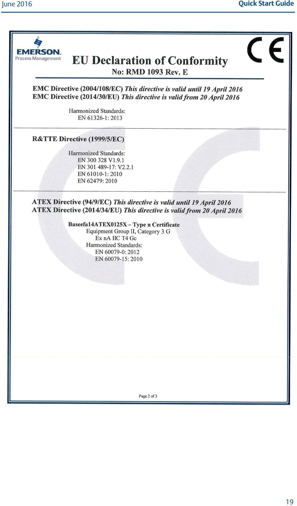
15 7.0 Product Certification Rev 1.0 Quick Start Guide 7.1 European Directive Information A copy of the EC Declaration of Conformity can be found at the end of the Quick Start Guide. The most recent revision of the EC Declaration of Conformity can be found at EmersonProcess.com/Rosemount. 7.2 Telecommunication Compliance All wireless devices require certification to ensure they adhere to regulations regarding the use of the RF spectrum. Nearly every country requires this type of product certification. Emerson is working with governmental agencies around the world to supply fully compliant products and remove the risk of violating country directives or laws governing wireless device usage. 7.3 FCC and IC This device complies with Part 15 of the FCC Rules. Operation is subject to the following conditions: This device may not cause harmful interference. This device must accept any interference received, including interference that may cause undesired operation. This device must be installed to ensure a minimum antenna separation distance of 20 cm from all persons. 7.4 Ordinary Location Certification As standard, the transmitter has been examined and tested to determine that the design meets the basic electrical, mechanical, and fire protection requirements by a nationally recognized test laboratory (NRTL) as accredited by the Federal Occupational Safety and Health Administration (OSHA). North America N5 U.S.A. Division 2 Certificate: (FM) Standards: FM Class , FM Class , FM Class , FM Class ; Markings: NI CL 1, DIV 2, GP A, B, C, D T4;Suitable for use in CL II, III, DIV 2, GP F, G T4;T4( 40 C T a 60 C) Special Condition for Safe Use (X): 1. When installed as Division 2 equipment, the Rosemount 1410 Smart Wireless Gateway shall be mounted within a tool-secured enclosure which meets the requirements of ANSI/ISA and be capable of accepting the applicable wiring methods per the NEC. 15

16 Quick Start Guide Canada N6 Canada Division 2 Certificate: (CSA) Standards: CAN/CSA C22.2 No. 0-10, CSA C22.2 No. 213-M1987 (R2013), CSA C22.2 No , ANSI/ISA , UL , 3rd Edition Markings: Suitable for CL I, DIV 2, GP A, B, C, D Temperature code: T4 (-40 C T a 70 C) Note Shall be powered by a class 2 power supply. Suitable for dry indoor locations only. Equipment must be installed in a suitable tool accessible enclosure subject to the end use application. Using the Rosemount 1410D and the Smart Wireless Field Link 781 in a hazardous location requires barriers between the two units. Europe N1 ATEX Type n Certificate: Baseefa14ATEX0125X Standards: EN : 2012, EN : 2010 Markings: II 3 G Ex na IIC T4 Gc, T4( 40 C T a +75 C), V MAX = 30 Vdc Special Conditions for Safe Use (X): 1. The equipment must be installed in an area of not more than Pollution Degree 2 as defined in IEC , and in an enclosure that provides a degree of protection of at least IP54 and meets the relevant requirements of EN and EN External connections to the equipment must not be inserted or removed unless either the area in which the equipment is installed is known to be non-hazardous, or the circuits connected have been de-energized. 3. The equipment is not capable of withstanding the 500 V electrical strength test as defined in clause of EN : This must be taken into account during installation. 4. When fitted, the surface resistivity of the remote antenna is greater than 1 GΩ. To avoid electrostatic charge build up, it must not be rubbed with a dry cloth or cleaned with solvents. International N7 IECEx Type n Certificate: IECEx BAS X Standards: IEC : 2011, IEC : 2010 Markings: Ex na IIC T4 Gc, T4(-40 C T a +75 C), V MAX = 30 Vdc Special Conditions for Safe Use (X): 1. The equipment must be installed in an area of not more than Pollution Degree 2 as defined in IEC , and in an enclosure that provides a degree of protection of at least IP54 and meets the relevant requirements of EN and EN External connections to the equipment must not be inserted or removed unless either the area in which the equipment is installed is known to be nonhazardous, or the circuits connected have been de-energized. 16

17 Quick Start Guide 3. The equipment is not capable of withstanding the 500 V electrical strength test as defined in clause of EN : This must be taken into account during installation. 4. When fitted, the surface resistivity of the remote antenna is greater than 1 GΩ. To avoid electrostatic charge build-up, it must not be rubbed with a dry cloth or cleaned with solvents. 17

18 Quick Start Guide Figure 8. Emerson 1410 Wireless Gateway Declaration of Conformity 18

19 Quick Start Guide 19
20 Quick Start Guide 20

21 Quick Start Guide Part Name Electronics Assembly China RoHS Rosemount 1410 List of Rosemount 1410 Parts with China RoHS Concentration above MCVs / Hazardous Substances Lead (Pb) Mercury (Hg) Cadmium (Cd) Hexavalent Chromium (Cr +6) Polybrominated biphenyls (PBB) Polybrominated diphenyl ethers (PBDE) X O O O O O SJ/T11364 This table is proposed in accordance with the provision of SJ/T O: GB/T O: Indicate that said hazardous substance in all of the homogeneous materials for this part is below the limit requirement of GB/T X: GB/T X: Indicate that said hazardous substance contained in at least one of the homogeneous materials used for this part is above the limit requirement of GB/T
22 * * Quick Start Guide , Rev DA Global Headquarters Emerson Process Management 6021 Innovation Blvd. Shakopee, MN 55379, USA or North America Regional Office Emerson Process Management 8200 Market Blvd. Chanhassen, MN 55317, USA or Latin America Regional Office Emerson Process Management 1300 Concord Terrace, Suite 400 Sunrise, FL 33323, USA Europe Regional Office Emerson Process Management Europe GmbH Neuhofstrasse 19a P.O. Box 1046 CH 6340 Baar Switzerland +41 (0) (0) Asia Pacific Regional Office Emerson Process Management Asia Pacific Pte Ltd 1 Pandan Crescent Singapore Enquiries@AP.EmersonProcess.com Middle East and Africa Regional Office Emerson Process Management Emerson FZE P.O. Box 17033, Jebel Ali Free Zone - South 2 Dubai, United Arab Emirates RFQ.RMTMEA@Emerson.com Linkedin.com/company/Emerson-Process-Management Twitter.com/Rosemount_News Facebook.com/Rosemount Youtube.com/user/RosemountMeasurement Google.com/+RosemountMeasurement Standard Terms and Conditions of Sale can be found at The Emerson logo is a trademark and service mark of Emerson Electric Co. AMS, Rosemount, and Rosemount logotype are trademarks of Emerson Process Management. WirelessHART is a registered trademark of the FieldComm Group. Microsoft and Internet Explorer are registered trademark of Microsoft Corporation in the United States and other countries. Windows is a trademark of Microsoft Corporation in the United States and other countries. All other marks are the property of their respective owners Emerson Process Management. All rights reserved.
Emerson Smart Wireless Gateway
 Product Data Sheet August 2015 00813-0200-4420, Rev GB Emerson Smart Wireless Gateway Gateway connects wireless self-organizing networks with any host system Easy configuration and management of self-organizing
Rosemount 708 Wireless Acoustic Transmitter
 Product Data Sheet January 2015 00813-0100-4708, Rev BB Rosemount 708 Wireless Acoustic Transmitter Improve energy efficiency and environmental compliance with acoustic monitoring of steam traps and pressure
Reliable Pressure Measurement with Remote Diaphragm Seals in Cold Weather Applications
 Reliable Pressure Measurement with Remote Diaphragm Reliable Pressure Measurement with Remote Diaphragm Introduction............................................................... page 1 Rosemount 3051S
Rosemount 248 Wireless Temperature Transmitter
 Rosemount 248 Wireless Temperature Transmitter Product Data Sheet May 2016 00813-0100-4248, Rev DB Standard temperature transmitter offers a wireless solution for process monitoring Optimize plant efficiency
Microcor Wireless Transmitter (MWT)
") Rohrback Cosasco Systems, Inc. Microcor Wireless Transmitter (MWT) Features: Highly Secure and Reliable Self Organizing Wireless Mesh Network High Resolution Metal Loss Measurement for all process environments
Rohrback Cosasco Systems, Inc. Microcor Wireless Transmitter (MWT) Features: Highly Secure and Reliable Self Organizing Wireless Mesh Network High Resolution Metal Loss Measurement for all process environments
RouteFinder SOHO. Quick Start Guide. SOHO Security Appliance. EDGE Models RF825-E, RF825-E-AP CDMA Models RF825-C-Nx, RF825-C-Nx-AP
 RouteFinder SOHO SOHO Security Appliance EDGE Models RF825-E, RF825-E-AP CDMA Models RF825-C-Nx, RF825-C-Nx-AP Quick Start Guide RouteFinder RF825 Series Quick Start Guide RouteFinder SOHO Security Appliance
Rosemount 333 HART Tri-Loop
 Product Data Sheet Rosemount 333 Rosemount 333 HART Tri-Loop HART-TO-ANALOG SIGNAL CONVERTER Convert a digital HART signal into three additional analog signals Easy to configure and install Accessory product
Rosemount 5300 and 5400 Series Terminal Compartment Spare Part Instruction
 Manual Supplement Rosemount 5300 and 5400 Series Rosemount 5300 and 5400 Series Terminal Compartment Spare Part Instruction Introduction..................................... page S-1 Safety Messages.................................
Quick Start Guide 00825-0100-4764, Rev DA March 2014. Rosemount 8714D (Calibration Standard) Magnetic Flowtube Simulator
 Magnetic Flowtube Simulator") Quick Start Guide 00825-0100-4764, Rev DA Rosemount 8714D (Calibration Standard) Magnetic Flowtube Simulator Quick Start Guide NOTICE This document provides basic guidelines for the Rosemount 8714D. It
Quick Start Guide 00825-0100-4764, Rev DA Rosemount 8714D (Calibration Standard) Magnetic Flowtube Simulator Quick Start Guide NOTICE This document provides basic guidelines for the Rosemount 8714D. It
THE WORLD'S FIRST WIRELESS GUIDED WAVE RADAR
 THE WORLD'S FIRST WIRELESS GUIDED WAVE RADAR Level measurements where you need them, however remote "Research 80% indicates that nearly of production downtime is preventable..." Ian Nimmo, Founder of the
Rosemount 333 HART Tri-Loop
 Product Data Sheet September 2014 00813-0100-4754, Rev GA Rosemount 333 HART Tri-Loop HART-to-Analog Signal Converter Convert a digital HART signal into three additional analog signals Easy to configure
Emerson Smart Wireless Gateway Solutions
 Product Data Sheet August 2014 00813-0300-4410, Rev AB Emerson Smart Wireless Gateway Solutions Gateway connects the WirelessHART self-organizing networks with any host system Easy configuration and management
PRO 5000 CPE 1D Quick Installation Guide
 PRO 5000 CPE 1D Quick Installation Guide Introduction This Quick Installation Guide covers the basic installation of the PRO 5000 CPE. For more information, refer to the relevant sections in the Product
Rosemount 1199 Submersible Seal
 Product Data Sheet July 2013 00813-0400-4016, Rev AA The Rosemount Submersible Seal design uses innovative DP level technology to measure level for top-down applications. For this design, the seal and
Rosemount 702 Wireless Discrete Transmitter
 Product Data Sheet August 2016 00813-0100-4702, Rev JB Rosemount 702 Wireless Discrete Transmitter An installation-ready solution that provides dual channel, discrete input, discrete output, or leak detection
Rosemount 752 FOUNDATION fieldbus Remote Indicator
 Product Data Sheet September 2014 00813-0100-4377, Rev DA Rosemount 752 FOUNDATION fieldbus Remote Indicator Two-wire segment powered device Displays up to eight values Link Master Capability Optional
AUPS-C20. User Manual MODEL: VESA Mount Intelligent UPS Module, 9 V ~ 28 V DC Input, 100 W Power Output, Network Remote Management Support
 AUPS-C20 UPS Module IEI Technology Corp. MODEL: AUPS-C20 VESA Mount Intelligent UPS Module, 9 V ~ 28 V DC Input, 100 W Power Output, Network Remote Management Support User Manual Page i Rev. 1.01 30 October,
AUPS Series. User Manual MODEL: VESA Mount Intelligent UPS Module 12 V DC Input or 9 V ~ 36 V DC Input Network Remote Management Support
 AUPS Series Power Module MODEL: AUPS Series VESA Mount Intelligent UPS Module 12 V DC Input or 9 V ~ 36 V DC Input Network Remote Management Support User Manual Rev. 1.00 November, 2008 Page i Revision
mysensors mysensors Wireless Sensors and Ethernet Gateway Quick Start Guide Information to Users Inside the Box mysensors Ethernet Gateway Quick Start
 mysensors Information to Users mysensors Wireless Sensors and Ethernet Gateway Quick Start Guide This equipment has been tested and found to comply with the limits for a Class B digital devices, pursuant
Rosemount 1199 Submersible Seal
 Product Data Sheet January 2015 00813-0400-4016, Rev BB The Rosemount Submersible Seal design uses innovative DP Level technology to measure level for top-down applications. For this design, the seal and
Energy Communication Unit (ECU)
") Altenergy Power System Energy Communication Unit (ECU) Installation and User Manual (For ECU-3 V3.8) ALTENERGY POWER SYSTEM INC. All rights reserved TABLE OF CONTENTS 1.0 Introduction... 2 2.0 Installation...
Altenergy Power System Energy Communication Unit (ECU) Installation and User Manual (For ECU-3 V3.8) ALTENERGY POWER SYSTEM INC. All rights reserved TABLE OF CONTENTS 1.0 Introduction... 2 2.0 Installation...
Rosemount 5708 3D Solids Scanners for Bulk Solids Inventory and Financial Reporting
 Rosemount 5708 3D Solids Scanners for Bulk Solids Inventory and Financial Reporting 1 Introduction This technical note provides an overview of the difficulties with inventory and financial reporting of
Import the Gateway Certificate to the Browser
 Import the Gateway Certificate to the Browser To remove the security certificate warning page during login the Gateway web interface by importing the Gateway certificate into the Internet Explorer and/or
Techniques for Interconnecting Smart Wireless Gateways to ProSoft RadioLinx Devices
 White Paper Techniques for Interconnecting Smart Wireless Gateways to ProSoft RadioLinx Devices EMERSON WIRELESS NETWORKS: PERVASIVE FIELD NETWORKS PFN Pervasive Field Networks (PFN) are a straight forward
FI8910W Quick Installation Guide. Indoor MJPEG Pan/Tilt Wireless IP Camera
 Model: FI8910W Quick Installation Guide (For Windows OS) (For MAC OS please go to page 17) Indoor MJPEG Pan/Tilt Wireless IP Camera Black White Package Contents IP Camera FI8910W with IR-Cut.x 1 DC Power
USER GUIDE. Ethernet Configuration Guide (Lantronix) P/N: 2900-300321 Rev 6
 P/N: 2900-300321 Rev 6") KRAMER ELECTRONICS LTD. USER GUIDE Ethernet Configuration Guide (Lantronix) P/N: 2900-300321 Rev 6 Contents 1 Connecting to the Kramer Device via the Ethernet Port 1 1.1 Connecting the Ethernet Port Directly
KRAMER ELECTRONICS LTD. USER GUIDE Ethernet Configuration Guide (Lantronix) P/N: 2900-300321 Rev 6 Contents 1 Connecting to the Kramer Device via the Ethernet Port 1 1.1 Connecting the Ethernet Port Directly
Wireless I/O Card. Wireless I/O Card. Introduction. DeltaV Product Data Sheet
 October 2014 Page 1 Redundant (WIOC) Fully redundant Wireless solution from to the Smart Wireless Field Link Optional simplex for smaller applications Seamless integration with DeltaV system and AMS Suite.
Router Setup Manual. NETGEAR, Inc. 4500 Great America Parkway Santa Clara, CA 95054 USA 208-10060-01 2006-03-17
 NETGEAR, Inc. 4500 Great America Parkway Santa Clara, CA 95054 USA 208-10060-01 2006-03-17 2006 by NETGEAR, Inc. All rights reserved. Trademarks NETGEAR is a trademark of Netgear, Inc. Microsoft, Windows,
Quick Installation Guide
 V48.01 Model: FI8919W Quick Installation Guide Outdoor Pan/Tilt Wireless IP Camera For Windows OS ------- Page 1 For MAC OS ------- Page 15 ShenZhen Foscam Intelligent Technology Co., Ltd Quick Installation
Energy Communication Unit (ECU)
") Altenergy Power System Energy Communication Unit (ECU) Installation and User Manual (For ECU-3 V3.7) Version:3.0 ALTENERGY POWER SYSTEM INC. All rights reserved TABLE OF CONTENTS 1.0 Introduction... 2
Altenergy Power System Energy Communication Unit (ECU) Installation and User Manual (For ECU-3 V3.7) Version:3.0 ALTENERGY POWER SYSTEM INC. All rights reserved TABLE OF CONTENTS 1.0 Introduction... 2
Wireless Router Setup Manual
 Wireless Router Setup Manual NETGEAR, Inc. 4500 Great America Parkway Santa Clara, CA 95054 USA 208-10082-02 2006-04 2006 by NETGEAR, Inc. All rights reserved. Trademarks NETGEAR is a trademark of Netgear,
Wireless LAN Outdoor Bridge Solution
 309-2273-001AA.fm Page 1 Monday, February 3, 2003 4:54 PM Quick Start Guide Wireless LAN Outdoor Bridge Solution 3CRWEASY96A Outdoor solution for secure long-distance wireless connections The 3Com Wireless
Model 3051 Pressure Transmitter with HART Protocol
 Model 3051 Pressure Transmitter with HART Protocol Start Step 1: Mount the Transmitter Step 2: Consider Housing Rotation Step 3: Set the Jumpers Step 4: Connect the Wiring and Power Up Step 5: Configure
Wi-Fi EOC Slave Quick Start Guide
 Wi-Fi EOC Slave Quick Start Guide Catalog 1. Hardware Setup... 3 1.1 Unpack Your EOC salve... 3 1.2 Hardware Features... 3 1.3 Position Your EOC Slave... 5 1.4 Cable Your EOC Slave... 5 2. Getting Started...
Configuring an A Series LED Sign Controller for your Network
 Configuring an A Series LED Sign Controller for your Network A Series LED displays from Optec support both serial and 10BaseT Ethernet communication. Serial communication via RS232 or RS485 is independent
3.5 EXTERNAL NETWORK HDD. User s Manual
 3.5 EXTERNAL NETWORK HDD User s Manual Table of Content Before You Use Key Features H/W Installation Illustration of Product LED Definition NETWORK HDD Assembly Setup the Network HDD Home Disk Utility
Ethernet Radio Configuration Guide
 Ethernet Radio Configuration Guide for Gateway, Endpoint, and Repeater Radio Units April 20, 2015 Customer Service 1-866-294-5847 Baseline Inc. www.baselinesystems.com Phone 208-323-1634 FAX 208-323-1834
Quick Installation Guide
 V2.01 Model: FI9821W Quick Installation Guide Indoor HD Pan/Tilt Wireless IP Camera Black White For Windows OS ------- Page 1 For MAC OS ------- Page 16 ShenZhen Foscam Intelligent Technology Co., Ltd
Configuration Manual English version
 Configuration Manual English version Frama F-Link Configuration Manual (EN) All rights reserved. Frama Group. The right to make changes in this Installation Guide is reserved. Frama Ltd also reserves the
Emerson Smart Firewall
 DeltaV TM Distributed Control System Product Data Sheet Emerson Smart Firewall The Emerson Smart Firewall protects the DeltaV system with an easy to use perimeter defense solution. Purpose built for easy
S-series Mass Connection Solutions
 DeltaV Distributed Control System Product Data Sheet March 2015 S-series Mass Connection Solutions Fast, easy and error-free cabinet wiring Modular design, improves reliability Lowers overall termination
Quick Installation Guide
 V46.01 Model: FI8918W Quick Installation Guide Indoor Pan/Tilt Wireless IP Camera Black White For Windows OS ------- Page 1 For MAC OS ------- Page 11 ShenZhen Foscam Intelligent Technology Co., Ltd Quick
Kantech IP Link Enhanced Ethernet Device
 Kantech IP Link Enhanced Ethernet Device Installation Manual Tear-out Quick Setup Sheet on last page! IP Link Installation Manual Table of Contents General Information...1 Copyright Info...1 Technical
Quick Setup Guide High Power Wireless Ethernet Converter WLI-TX4-G54HP
 Quick Setup Guide High Power Wireless Ethernet Converter WLI-TX4-G54HP This guide is intended to help you quickly and easily install your High Power Wireless Ethernet Converter. For more setup and configuration
Quick Installation Guide
 Quick Installation Guide (For Windows & Mac OS) Outdoor Wireless IP Camera Package Contents V1.1 IP Camera Power Adapter Resource CD Ethernet Cable Mounting Bracket(except FI8919) Wi-Fi Antenna Quick Installation
BiPAC 7404V series. VoIP/(802.11g) ADSL2+ (VPN) Firewall Router. Quick Start Guide
 ADSL2+ (VPN) Firewall Router. Quick Start Guide") BiPAC 7404V series VoIP/(802.11g) ADSL2+ (VPN) Firewall Router Quick Start Guide VoIP/(802.11g) ADSL2+ (VPN) Firewall Router For more detailed instructions on configuring and using the Billion VoIP/(802.11g)
BiPAC 7404V series VoIP/(802.11g) ADSL2+ (VPN) Firewall Router Quick Start Guide VoIP/(802.11g) ADSL2+ (VPN) Firewall Router For more detailed instructions on configuring and using the Billion VoIP/(802.11g)
Installation Guide Wireless 4-Port USB Sharing Station. GUWIP204 Part No. M1172-a
 Installation Guide Wireless 4-Port USB Sharing Station 1 GUWIP204 Part No. M1172-a 2011 IOGEAR. All Rights Reserved. PKG-M1172-a IOGEAR, the IOGEAR logo, MiniView, VSE are trademarks or registered trademarks
C24-CAMANL Video Server/Encoder
 C24-CAMANL Video Server/Encoder User s Guide Table of Contents CHAPTER 1 INTRODUCTION... 1 Overview... 1 Physical Details - Video Server... 2 Package Contents... 3 CHAPTER 2 BASIC SETUP... 4 System Requirements...
1.1 Fill fluids. Rosemount DP Level Fill Fluid Specifications July 2015. Technical Note 00840-2100-4016, Rev DB
 Rosemount DP Level Fill Fluid Specifications 1.1 Fill fluids Silicone 2 Silicone 2 for Vacuum Applications Silicone 74 Silicone 74 for Vacuum Applications Silicone 75 Silicone 75 for Vacuum Applications
EMERSON S ROSEMOUNT PROJECT MANAGEMENT OFFICE. Delivering project success for your instrumentation
 EMERSON S ROSEMOUNT PROJECT MANAGEMENT OFFICE Delivering project success for your instrumentation One Less Project YOUR INSTRUMENTATION IS ON TRACK. Capital projects always come down to the details. The
Chapter 1 Installing the Gateway
 Chapter 1 Installing the Gateway This chapter describes how to set up the wireless voice gateway on your Local Area Network (LAN), connect to the Internet, and perform basic configuration. For information
Disclaimers. Important Notice
 Disclaimers Disclaimers Important Notice Copyright SolarEdge Inc. All rights reserved. No part of this document may be reproduced, stored in a retrieval system, or transmitted, in any form or by any means,
Hardware overview. Package contents MSM310, documentation, two 2.4-GHz (2-dBi) / 5-GHz (2-dBi) dual-mode omnidirectional antennas.
 / 5-GHz (2-dBi) dual-mode omnidirectional antennas.") VIEW Certified The MSM310 is a Wi-Fi Alliance authorized Wi-Fi CERTIFIED 802.11a/b/g product. The Wi-Fi CERTIFIED Logo is a certification mark of the Wi-Fi Alliance. The MSM310 is certified under the SpectraLink
VIEW Certified The MSM310 is a Wi-Fi Alliance authorized Wi-Fi CERTIFIED 802.11a/b/g product. The Wi-Fi CERTIFIED Logo is a certification mark of the Wi-Fi Alliance. The MSM310 is certified under the SpectraLink
OUTDOOR IR NETWORK CAMERA Series
 OUTDOOR IR NETWORK CAMERA Series INSTALLATION GUIDE Please read instructions thoroughly before operation and retain it for future reference. 1. OVERVIEW 1.1 Package Content Network camera Installation
TCP/IP MODULE CA-ETHR-A INSTALLATION MANUAL
 TCP/IP MODULE CA-ETHR-A INSTALLATION MANUAL w w w. c d v g r o u p. c o m CA-ETHR-A: TCP/IP Module Installation Manual Page Table of Contents Introduction...5 Hardware Components... 6 Technical Specifications...
Rosemount 751 Field Signal Indicator
 Rosemount 751 Field Signal Indicator Product Data Sheet August 2014 00813-0100-4378, Rev FA Available with an LCD display or analog meter Compact, rugged, and designed for industrial environments Available
NeoGate TA Series Installation Guide
 NeoGate TA Series Installation Guide Version 1.2 Date: April 1, 2015 Yeastar Information Technology Co. Ltd Contents 1. Preparation before Installation... 3 2. Hardware Specifications... 5 2.1 Overview...
Quick Start Guide. RV 120W Wireless-N VPN Firewall. Cisco Small Business
 Quick Start Guide Cisco Small Business RV 120W Wireless-N VPN Firewall Package Contents Wireless-N VPN Firewall Ethernet Cable Power Adapter Quick Start Guide Documentation and Software on CD-ROM Welcome
* DISCLAIMER: Contents. How to Use This Guide: COMMERCIAL INSTALL GUIDE 2
 COMMERCIAL INSTALL GUIDE 2 Contents How to Use This Guide: The first section of this guide is designed to assist you with the installation of your DECK Monitoring hardware. The revenue grade meter and
1 Serial RS232 to Ethernet Adapter Installation Guide
 Installation Guide 10/100 Mbps LED (amber color ) Link/Activity LED (green color ) 1. Introduction Thank you for purchasing this 1-port RS232 to Ethernet Adapter (hereinafter referred to as Adapter ).
ETHERNET WEATHER STATION CONNECTIONS Application Note 33
 ETHERNET WEATHER STATION CONNECTIONS Application Note 33 With WeatherLink and a Device Server INTRODUCTION It is possible to substitute an Ethernet connection for the direct USB or serial connection that
Operating Instructions
 Operating Instructions RFID-RDR-1-xxx R. STAHL HMI Systems GmbH Im Gewerbegebiet Pesch 14 50767 Köln Version 1.00.00 Issue date: 09.03.2011 Table of contents Table of contents Description Page Table of
Users manual. TCW181B-CM_R1 Page 1
 Ethernet controller TCW181B-CM Users manual 1. Short description TCW181B-CM is 8-channel Ethernet relay board, which is designed to work in IP-based networks and managed by WEB interface or SNMP programs.
BW-500 BED WEIGHER USER MANUAL
 BW-500 BED WEIGHER USER MANUAL 0 1 TABLE OF CONTENTS SPECIFICATION... 3 Equipment... 4 INSTALLING WEIGH BEAM... 5 PREPARATION FOR MEASUREMENT... 6 DP3800 Indicator... 8 POWER SUPPLY... 8 PANEL... 9 KEY
S-series SQ Controller
 DeltaV Distributed Control System Product Data Sheet December 2015 S-series SQ Controller Scalable controllers Quick assembly Easy-to-use Field proven architecture Designed for Electonic Marshalling Advanced
WxGoos-1 Climate Monitor Installation Instructions Page 1. Connections. Setting an IP Address
 Instructions Page 1 Connections The WxGoos-1 is a self-contained web server and requires 6vdc of power at 300ma. A center-positive 2.1 mm plug is used. There are five ports: 1. 10/100 Ethernet RJ-45 receptacle
DI-634M. Check Your Package Contents. This product can be set up using any current web browser, i.e., Internet Explorer 6 or Netscape Navigator 7.
 This product can be set up using any current web browser, i.e., Internet Explorer 6 or Netscape Navigator 7. DI-634M 108G MIMO Wireless Router Before You Begin 1. If you purchased this router to share
Installation Guide. Wireless N Access Point EAP110/EAP120/EAP220
 Installation Guide Wireless N Access Point EAP110/EAP120/EAP220 CONTENTS Network Topology 01 Hardware Overview 02 Hardware Installation 05 1. Installation Requirements... 05 2. Mounting Bracket... 05
WLAN Outdoor CPE For 2.4G. Quick Installation Guide
 WLAN Outdoor CPE For 2.4G Quick Installation Guide Part I: External Installation Direction A. Check the parts in your box CPE SET 1 DC 12V/1.5A Power Adapter 1 PoE DC Injector 1 Hose Clamps 2 Manual &
Connecting the DG-102S VoIP Gateway to your network
 Contents of Package: DG-102S VoIP Station Gateway Power adapter CD-ROM, including User s Manual Quick Install Guide Requirements: RS-232 Console Cable Two RJ-45 CAT-5 Straight-Through Cables For more information
User Manual. Sipura SPA-2100 ATA with PC Router. January 2005 v1. Linhagratuita grupo csdata www.linhagratuita.com.br
 User Manual Sipura SPA-2100 ATA with PC Router January 2005 v1 Linhagratuita grupo csdata www.linhagratuita.com.br Disclaimer Please Read: This document contains implementation examples and techniques
Check Your Package Contents. CD-ROM containing Manual and Warranty
 This product can be set up using any current web browser, i.e., Internet Explorer 6 or Netscape Navigator 6.2.3. DVA-G3340S Wireless VoIP Router Before You Begin If you purchased this Router to share your
EZ-View Network Communications Guide www.cszindustrial.com
 Network Communications Guide EzView Network Communications Guide RevB July 2013 (V2.2) Supersedes: RevA (May 2011) Cincinnati Sub-Zero Products, LLC 513-772-8810 12011 Mosteller Road Cincinnati, Ohio 45241
SLC 5/05 Processors Firmware/Operating System ControlFLASH Upgrade
 Installation Instructions SLC 5/05 Processors Firmware/Operating System ControlFLASH Upgrade Catalog Numbers 1747-DU501 Topic Page System Requirements 3 Install ControlFLASH 3 Prior to Running ControlFLASH
10/2011 - English Edition 1. Quick Start Guide. NWA1100N-CE CloudEnabled Business N Wireless Access Point
 10/2011 - English Edition 1 Quick Start Guide NWA1100N-CE CloudEnabled Business N Wireless Access Point Package Contents - 1 x ZyXEL NWA1100N-CE Access Point - 2 x Detachable Antennas - 1 x Power Adapter
TL-PS310U Single USB 2.0 Port MFP and Storage Server
 TL-PS310U Single USB 2.0 Port MFP and Storage Server Rev: 2.0.0 1910010313 Contents Chapter 1 Introduction... 1 1.1 Product Overview...1 1.2 Network Management...1 1.3 Components and Features...1 1.4 Hardware
User Manual. PePWave Surf / Surf AP Indoor Series: Surf 200, E200, AP 200, AP 400. PePWave Mesh Connector Indoor Series: MC 200, E200, 400
 User Manual PePWave Surf / Surf AP Indoor Series: Surf 200, E200, AP 200, AP 400 PePWave Mesh Connector Indoor Series: MC 200, E200, 400 PePWave Surf AP Series: Surf AP 200-X, E200-X, 400-X PePWave Surf
WLAN600 Wireless IP Phone Administrator s Guide
 WLAN600 Wireless IP Phone Administrator s Guide Trademark Acknowledgement All brand names are trademarks or registered trademarks of their respective companies. Disclaimer This document is supplied by
User Manual. EtherUSB
 User Manual EtherUSB USB Ethernet Access Point for PDA V 2.0 Clarinet Systems, Inc. Clarinet Systems, Inc. http://www.clarinetsys.com Page 1 Publication Revision No. Control Table Rev. No. Date Contents
1. Hardware Installation
 4 Port 10/100M Internet Broadband Router with USB Printer server Quick Installation Guide #4824904AXZZ0 1. Hardware Installation A. System Requirement Before you getting started, make sure that you meet
QUICK START GUIDE. Cisco C170 Email Security Appliance
 1 0 0 1 QUICK START GUIDE Email Security Appliance Cisco C170 303357 Cisco C170 Email Security Appliance 1 Welcome 2 Before You Begin 3 Document Network Settings 4 Plan the Installation 5 Install the Appliance
P-660HN-51. 802.11n Wireless ADSL2+ 4-port Gateway DEFAULT LOGIN DETAILS. Firmware Version 1.10 Edition 1, 9/2010. IP Address: http://192.168.1.
 P-660HN-51 802.11n Wireless ADSL2+ 4-port Gateway Firmware Version 1.10 Edition 1, 9/2010 DEFAULT LOGIN DETAILS IP Address: http://192.168.1.1 User Name: admin Password: 1234 www.zyxel.com Copyright 2010
FOR MORE INFORMATION. 125 8880 or from a non-telstra phone 13 2200 and say pre-paid telstra.com/ppmbb visit a telstra store or partner
 FOR MORE INFORMATION 125 8880 or from a non-telstra phone 13 2200 and say pre-paid telstra.com/ppmbb visit a telstra store or partner getting to know your telstra pre-paid 4G WI-FI (760S) LET S GET THIS
UBIQUITI BRIDGE CONFIGURATION PROCEDURE (PowerStation & NanoStation Units ONLY)
") UBIQUITI BRIDGE CONFIGURATION PROCEDURE (PowerStation & NanoStation Units ONLY) Hardware Installation 1. Initial placement for programming and configuration purposes should be performed in an indoor environment.
UBIQUITI BRIDGE CONFIGURATION PROCEDURE (PowerStation & NanoStation Units ONLY) Hardware Installation 1. Initial placement for programming and configuration purposes should be performed in an indoor environment.
c. Securely insert the Ethernet cable from your cable or DSL modem into the Internet port (B) on the WGT634U. Broadband modem
 on the WGT634U. Broadband modem") Start Here Follow these instructions to set up your router. Verify That Basic Requirements Are Met Assure that the following requirements are met: You have your broadband Internet service settings handy.
Start Here Follow these instructions to set up your router. Verify That Basic Requirements Are Met Assure that the following requirements are met: You have your broadband Internet service settings handy.
Terminal Boxes Series 8146
 Series > Enclosures in shock-resistant glass fibre reinforced polyester resin > basic enclosure sizes various heights > Fitted according to the customer's requirements > For terminals up to max. 00 mm
BODi rs BD004 Series Bandwidth-on-Demand Internet with Reliability and Survivability. Quick Start Guide NOTES
 NOTES BODi rs BD004 Series Bandwidth-on-Demand Internet with Reliability and Survivability Quick Start Guide This is a Class A device and is not intended for use in a residential environment. Important
DOORKING SYSTEMS 1830 SERIES NETWORK WORKSHOP LAN APPLICATIONS ACCESS CONTROL SOLUTIONS LOCAL AREA NETWORK (LAN) CONNECTION REV 04.
 CONNECTION REV 04.") DOORKING SYSTEMS ACCESS CONTROL SOLUTIONS 1830 SERIES NETWORK WORKSHOP LAN APPLICATIONS REV 04.11 LOCAL AREA NETWORK (LAN) CONNECTION Ethernet Connection: An Ethernet Cable, or wireless connection must
DOORKING SYSTEMS ACCESS CONTROL SOLUTIONS 1830 SERIES NETWORK WORKSHOP LAN APPLICATIONS REV 04.11 LOCAL AREA NETWORK (LAN) CONNECTION Ethernet Connection: An Ethernet Cable, or wireless connection must
User Guide. Guide d utilisation Guida dell'utente Benutzerhandbuch Guía del usuario Guia do Usuário WNA-100. Wireless Network Adapter
 WNA-100 Wireless Network Adapter User Guide Guide d utilisation Guida dell'utente Benutzerhandbuch Guía del usuario Guia do Usuário www.xerox.com/office/wna Copyright 2007 Xerox Corporation. All Rights
NeoGate TA Series Quick Installation Guide
 NeoGate TA Series Quick Installation Guide Version: V1.1 Yeastar Technology Co., Ltd. Date: November 18, 2014 http://www.yeastar.com 1/15 Contents NeoGate TA Series Quick Installation Guide 1. Preparation
QUICK START GUIDE. Cisco S170 Web Security Appliance. Web Security Appliance
 1 0 0 0 1 1 QUICK START GUIDE Web Security Appliance Web Security Appliance Cisco S170 303417 Cisco S170 Web Security Appliance 1 Welcome 2 Before You Begin 3 Document Network Settings 4 Plan the Installation
PowerCommand 500/550 Remote Monitoring System
 PowerCommand 500/550 Remote Monitoring System Complete remote monitoring of your power system The PowerCommand 500 series provides a convenient means of remotely monitoring generator sets, transfer switches,
Chapter 1 Connecting the Router to the Internet
 Chapter 1 Connecting the Router to the Internet This chapter describes how to set up the router on your Local Area Network (LAN) and connect to the Internet. It describes how to set up your wireless ADSL
Installation and Operation Guide
 www.aja.com Quick Start Guide Introduction This Quick Start Guide provides a basic overview of KUMO configuration. It is not meant as a substitute for the detailed information found in the KUMO Manual,
HDCVI Series DVR Quick Start Guide
 HDCVI Series DVR Quick Start Guide Version 1.1.0 Welcome Thank you for purchasing our HDCVI DVR! This quick start guide will help you become familiar with our HDCVI DVR in a very short time. Before installation
EnGenius ERB9250 300M Range Extender. Quick Start Guide
 EnGenius ERB9250 300M Range Extender Quick Start Guide Package Contents One ERB9250 300M Range Extender One 12V/1A power adapter Two 2dBi 2.4GHz SMA antennas One Ethernet cable One CD-ROM with user s manual
WAVE BLUETOOTH MUSIC ADAPTER
 WAVE BLUETOOTH MUSIC ADAPTER FOR WAVE SYSTEMS Owner s Guide Bedienungsanleitung Guía de usuario Notice d utilisation Manuale di istruzioni Gebruiksaanwijzing Tab 8, 16 Tab 7, 15 Tab 6, 14 Tab 5, 13 Tab
GV-Data Capture V3 Series User's Manual
 GV-Data Capture V3 Series User's Manual Before attempting to connect or operate this product, please read these instructions carefully and save this manual for future use. 2006 GeoVision, Inc. All rights
AXIS 5810 A Bluetooth Print Plug. Quick Start
 AXIS 5810 AXIS 5810 A Bluetooth Print Plug Quick Start BLUETOOTH is a trademark owned by its proprietor and used by Axis Communications AB under license 1 AXIS 5810 Regulatory Information Regulatory Information
How to convert a wireless router to be a wireless. access point
 How to convert a wireless router to be a wireless access point Thanks for purchasing Edimax Wireless Router. This instruction can be applied if you want to keep your wired router and you need Edimax Wireless