Oscilloscope Probes and Probe Accessories
|
|
|
- Rebecca Lambert
- 9 years ago
- Views:
Transcription
1 Oscilloscope Probes and Probe Accessories
2 PROBE SELECTION GUIDE Teledyne LeCroy has a wide variety of world class probes and amplifiers to compliment its product line. From the ZS high impedance active probes to the WaveLink differential probing system which offers bandwidths up to 25 GHz, Teledyne LeCroy probes and probe accessories provide optimum mechanical connections for signal measurement. Front Cover: ZS Series High Impedence Active Probes WaveAce Oscilloscopes WaveJet Oscilloscopes WaveSurfer 3000 Oscilloscopes WaveSurfer 10 / MXs-B / MSO MXs-B Oscilloscopes HDO4000 / HDO4000-MS High Definition Oscilloscopes WaveRunner 6 Zi Oscilloscopes HDO6000 / HDO6000-MS High Definition Oscilloscopes HDO8000 / HDO8000-MS High Definition Oscilloscopes MDA800 Motor Drive Analyzers HRO 12-bit Oscilloscopes WavePro/SDA/DDA/7 Zi/7 Zi-A Oscilloscopes WaveMaster/SDA/DDA/8 Zi/Zi-B Oscilloscopes LabMaster 9 Zi-A Oscilloscopes LabMaster 10 Zi-A Oscilloscopes Active Voltage Probes - p. 4-7 ZS1000 ZS1500 ZS2500 ZS4000 Current Probes - p CP030 CP030A CP031 CP031A CP150 CP500 CA10 Differential Probes - p ZD200 ZD500 ZD1000 ZD1500 AP033 D410-PS D420-PS D400A-AT D610-PS D620-PS D600A-AT D830-PS D1030-PS D1330-PS D1305-A-PS D1605-A-PS D2005-A-PS D2505-A-PS High Voltage Differential Probes - p HVD3102 HVD3106 HVD3106-6M HVD3206 HVD3605 ADP300 ADP305 AP031 2

3 WaveAce Oscilloscopes WaveJet Oscilloscopes WaveSurfer 3000 Oscilloscopes WaveSurfer 10 / MXs-B / MSO MXs-B Oscilloscopes HDO4000 / HDO4000-MS High Definition Oscilloscopes WaveRunner 6 Zi Oscilloscopes HDO6000 / HDO6000-MS High Definition Oscilloscopes HDO8000 / HDO8000-MS High Definition Oscilloscopes MDA800 Motor Drive Analyzers HRO 12-bit Oscilloscopes WavePro/SDA/DDA/7 Zi/7 Zi-A Oscilloscopes WaveMaster/SDA/DDA/8 Zi/Zi-B Oscilloscopes LabMaster 9 Zi-A Oscilloscopes LabMaster 10 Zi-A Oscilloscopes Differential Amplifiers - p DXC200 DA101 DA1855A DA1855A-PR2 DA1855A-PR2-RM DA1855A-RM DXC-5100 DXC100A High Voltage Probes - p HVP120 PPE1.2KV PPE2KV PPE4KV PPE5KV PPE6KV Optical Probes - p OE425 OE455 OE525 OE555 OE695G Passive Probes - p PP006A PP007-WR PP008 PP009 PP010 PP011 PP016 PP017 PP018 PP019 PP020 Probe Adapters - p CA10 TPA10 Transmission Line Probes - p PP066 Note: Some probes require purchase of the amplifier and platform/cable assembly separately Reference detailed literature for more information. 3

4 ACTIVE VOLTAGE PROBES 4
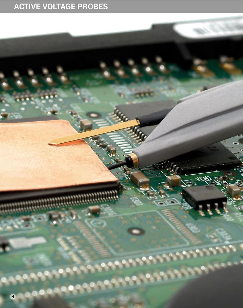
5 ACTIVE VOLTAGE PROBES Engineers must commonly probe high-frequency signals with high signal fidelity. Typical passive probes with high input R and C provide good response at lower frequencies, but inappropriately load the circuit and distort signals at higher frequencies. Active voltage probes feature both high input R and low input C to reduce circuit loading across the entire probe/oscilloscope bandwidth. With low circuit loading and a form factor that allows probing in confined areas, the active voltage probe becomes the everyday probe for all different types of signals and connection points. Teledyne LeCroy Active Voltage Probe Model Numbers: ZS1000 ZS1500 ZS2500 ZS4000 Opposite page: ZS Series High Impedance Active Probe 5

6 ZS SERIES ACTIVE PROBES The ZS Series probes are high impedance, low capacitance active probes that maintain high signal fidelity through 4 GHz. A small form factor and a wide variety of accessories ensures the ZS probe meets every difficult probing challenge. Teledyne LeCroy Active Voltage Probe Model Numbers: ZS1000 ZS1500 ZS2500 ZS4000 Engineers must commonly probe high frequency signals with high signal fidelity. Typical passive probes with high input R and C provide good response at lower frequencies but inappropriately load the circuit and distort signals at higher frequencies. The ZS Series features both high input R (1 MΩ) and low input C (0.6 pf and 0.9 pf) to reduce circuit loading across the entire probe/oscilloscope bandwidth. The ZS1000 is ideal for MHz oscilloscopes. The ZS1500 is ideal for 1 GHz oscilloscopes, the ZS2500 is ideal for 2 GHz oscilloscopes, and the ZS4000 is ideal for 2.5 GHz and 4 GHz oscilloscopes. PK-ZS-010 Channel ID Colored Clips ZS4000 PK-ZS-019 Freehand Probe Holder PK-ZS-006 Right Angle Socket PACC-PT005 Bent Tip PACC-PT003 IC Tip PK-ZS-001 Probe Tip - Standard PK-ZS-017 Pogo Tip PK-ZS-014 Y-Lead Adapter PK-ZS-023 Straight Pin Lead - 13cm PK-ZS-022 Straight Pin Lead - 7cm PACC-LD003 Right Angle Pin Lead - 5cm PACC-LD004 Right Angle Pin Lead - 10cm PK-ZS mm Square Pin Adapter PK-ZS-021 Ground Blade - Narrow PK-ZS-016 Offset Ground (Z Lead) PK-ZS-020 Pogo Ground Lead PK-ZS-015 Ground Blade - Wide PK-ZS-009 Copper Tape PK-ZS mm PCB Adapter PK-ZS-007R Microclip Sprung Hook, Red PK-ZF-025 QFPIC Clip Yellow - Short PK-ZF-025 QFPIC Clip Green - Short PK-ZS-007B Microclip Sprung Hook, Black 6

7 ZS SERIES ACTIVE PROBES PK-ZS-010 Channel ID Colored Clips ZS1000 ZS1500 ZS2500 PACC-MS005 Freehand Probe Holderk PK-ZS mm Square Pin Adapter PK-ZS-006 Right Angle Socket PACC-PT005 Bent Tip PACC-PT003 IC Tip PK-ZS-001 Probe Tip - Standard Qty: 3 PK-ZS-013 Pogo Tip PK-ZS-005 Y-Lead Adapter PK-ZS-004 Single Lead - Long PK-ZS-003 Single Lead - Short PACC-LD003 Right Angle Pin Lead - 5cm PACC-LD004 Right Angle Lead - Long PK-ZS-008 Ground Blade - Narrow PK-ZS-002 Offset Ground PACC-CD008 Pogo Ground Lead PK-ZS-011 Ground Blade - Wide PK-ZS-009 Copper Tape PK-ZS-007R Microclip Sprung Hook, Red PK-ZS-007B Microclip Sprung Hook, Black Ordering Information Product Description 4 GHz, 0.6 pf, 1 MΩ High Impedance Active Probe 2.5 GHz, 0.9 pf, 1 MΩ High Impedance Active Probe 1.5 GHz, 0.9 pf, 1 MΩ High Impedance Active Probe 1 GHz, 0.9 pf, 1 MΩ High Impedance Active Probe Set of 4 ZS2500, 2.5 GHz, 0.9 pf, 1 MΩ High Impedance Active Probes Set of 4 ZS1500, 1.5 GHz, 0.9 pf, 1 MΩ High Impedance Active Probes Set of 4 ZS1000, 1 GHz, 0.9 pf, 1 MΩ High Impedance Active Probes Product Code ZS4000 ZS2500 ZS1500 ZS1000 ZS2500-QUADPAK ZS1500-QUADPAK ZS1000-QUADPAK Specifications ZS1000 ZS1500 ZS2500 ZS4000 Electrical Characteristics Probe Bandwidth 1 GHz 1.5 GHz 2.5 GHz 4 GHz Input Capacitance 0.9 pf 0.6 pf DC Input Resistance 1 MΩ Probe Offset Range N/A ±12 V Attenuation 10 Input Dynamic Range ±8 V Non-destruct Voltage 20 V General Characteristics Cable Length 1.3 m Standard Accessory/Quantity ZS1000 Replacement ZS1500 Accessory Description Part Number ZS2500 ZS mm PCB Adaptor PK-ZS mm Square Pin Adapter PK-ZS mm Square Pin Adaptor PK-ZS IC Tip PACC-PT Bent Tip PACC-PT Channel ID Clips (Set of 4 colors) PK-ZS Copper Tape Pad PK-ZS Freehand Probe Holder PK-ZS Freehand Probe Holder PACC-MS005 1 Ground Blade Narrow PK-ZS Ground Blade Wide PK-ZS Ground Blade, Narrow PK-ZS Ground Blade, Wide PK-ZS Micro-Grabber Pair PK-ZS-007R and PK-ZS-007B 1 2 Offset Ground PK-ZS ZS1000 Accessory Description Replacement ZS1500 Part Number ZS2500 ZS4000 Offset Ground Z Lead PK-ZS Pogo Ground Lead PK-ZS Pogo Ground Lead PACC-CD008 1 Pogo Tip PK-ZS Pogo Tip PK-ZS Probe Tip Standard PK-ZS QFPIC Clips (set of 2) PK-ZS Right Angle Lead Long PACC-LD Right Angle Lead Short PACC-LD Right Angle Socket PK-ZS Straight Pin Lead Long PK-ZS Straight Pin Lead Long PK-ZS Straight Pin Lead Short PK-ZS Straight Pin Lead Short PK-ZS Y Lead Adapter PK-ZS Y Lead Adaptor PK-ZS

8 CURRENT PROBES 8

9 CURRENT PROBES Teledyne LeCroy current probes do not require the breaking of a circuit or the insertion of a shunt to make accurate and reliable current measurements. Based on a combination of Hall effect and transformer technology, Teledyne LeCroy current probes are ideal for making accurate AC, DC, and impulse current measurements. Wide Range of Applications Teledyne LeCroy current probes are available in a variety of models for a wide range of applications. The full range of Teledyne LeCroy current probes includes models with bandwidths up to 100 MHz, peak currents up to 700 A and sensitivities to 1 ma/div. Teledyne LeCroy current probes are often used in applications such as the design and test of switching power supplies, motor drives, electric vehicles, and uninterruptible power supplies. Teledyne LeCroy Current Probe and Adapter Model Numbers: CP030 CP030A CP031 CP031A CP150 CP500 DCS015 CA10 High Sensitivity The CP030A and CP031A provide a high sensitivity of 1 ma/div. This allows for more precise low current measurements on Teledyne LeCroy oscilloscopes. When used with HDO high definition oscilloscopes with HD4096 technology, users will obtain highly accurate, low current waveforms with unmatched 12-bit resolution for improved debug and analysis. Fully Integrated All Teledyne LeCroy current probes are powered through the Teledyne LeCroy ProBus connection and require no additional hardware. Along with providing power, the ProBus connection allows the current probe and oscilloscope to communicate, resulting in current waveforms automatically displayed on screen in Amps, and calculated power traces scaled correctly in Watts. This full integration also allows for Degauss and Autozero functions to be done directly from the oscilloscope s user interface. Deskew Calibration Source The DCS015 deskew calibration source has both voltage and current timealigned signals, which enables the precise deskew of voltage and current probes. Most voltage probes along with the CP030, CP030A, CP031, and CP031A are compatible with the DSC015. Opposite page: CP031, 30A, 100 MHz Current Probe. 9


10 CURRENT PROBES Features ProBus active probe interface withautomatic scaling in A/div Autozero and degauss capabilities built into instrument s user interface Wide range of input currents and bandwidth capabilities Teledyne LeCroy Current Probe and Adapter Model Numbers: CP030 CP030A CP031 CP031A CP150 CP500 DCS015 CA10 CP A continuous current rms 50 A current peak 50 MHz bandwidth CP030A 30 A continuous current rms 50 A current peak 50 MHz bandwidth 1 ma/div sensitivity CP A continuous current rms 50 A current peak 100 MHz bandwidth CP031A 30 A continuous current rms 50 A current peak 100 MHz bandwidth 1 ma/div sensitivity CP A continuous current rms 500 A current peak CP MHz bandwidth 500 A continuous current rms 700 A current peak 2 MHz bandwidth 10 DCS015 Precise deskew of voltage and current probes. Compatible with the CP031,CP031A, CP030, and CP030A

11 CURRENT PROBES CA10 Current Sensor Adapter The CA10 enables a third-party current measurement device to operate like a Teledyne LeCroy probe. The CA10 is programmable and customizable to work with third-party current measurement devices that output voltage or current signals proportional to measured current. (See page 48 for more information and specifications). Specifications CP030 CP030A CP031 CP031A CP150 CP500 Electrical Characteristics* Max. Continuous Input Current 30 A rms 150 A rms 500 A rms Bandwidth 50 MHz 100 MHz 10 MHz 2 MHz Rise Time (typical) 7 ns 3.5 ns 35 ns 175 ns Max. Peak Current 300 A 50 A peak (non-continuous) peak non-continuous; 700 A peak 500 Apeak 30 µs non-continuous Output Voltage 0.1 V/A 0.1 V/A & 1 V/A 0.1 V/A 0.1 V/A & 1 V/A 0.01 V/A Max Continuous Input Current at 1 V/A (100mA/div or less) 5 A 5 A Offset Range at 1V/A (100mA/div or less) ±5 A ±5 A Minimum Sensitivity 10 ma/div 1 ma/div 10 ma/div 1 ma/div 100 ma/div Low-Frequency Accuracy 1% AC Noise at 20 MHz BWL 2.5 ma 150 µa 2.5 ma 150 µa 6.0 ma 8.0 ma Coupling AC, DC, GND General Characteristics Cable Length 1.5 m 2 m 6 m Weight 240 g 260 g 240 g 260 g 500 g 630 g Max. Conductor Size (Diameter) 5 mm 20 mm Interface ProBus, 1 MΩ only Usage Environment Indoor Operating Temperature 0 C to 40 C Max. Relative Humidity 80% Max. Altitude 2000 m Maximum Insulated Wire Voltage 300 V CAT I 600 V CAT II, 300 V CAT III * Electrical Characteristics Guaranteed at 23 C ±3 C The CP031 and CP030 require the Teledyne LeCroy oscilloscope to be running firmware version or greater. The CP031A and CP030A require firmware version 7.8.x.x or greater. Ordering Information Product Description Product Code ProBus Current Sensor Adapter CA10 Set of 4 CA10, ProBus Current Sensor Adapters CA10-QUADPAK 30 A; 50 MHz Current Probe AC/DC; 30 Arms; 50 A Peak Pulse CP A; 50 MHz High Sensitivity Current Probe AC/DC; 30 Arms; 50 A Peak Pulse CP030A 30 A; 100 MHz Current Probe AC/DC; 30 Arms; 50 A Peak Pulse CP A; 100 MHz High Sensitivity Current Probe AC/DC; 30 Arms; 50 A Peak Pulse CP031A 150 A; 10 MHz Current Probe AC/DC; 150 Arms; 500 A Peak Pulse CP A; 2 MHz Current Probe AC/DC; 500 Arms; 700 A Peak Pulse CP500 Deskew Calibration Source for CP031,CP031A, CP030, CP030A and AP015 DCS015 11
 7 ns 3.5 ns 35 ns 175 ns Max.")
12 12 DIFFERENTIAL PROBES
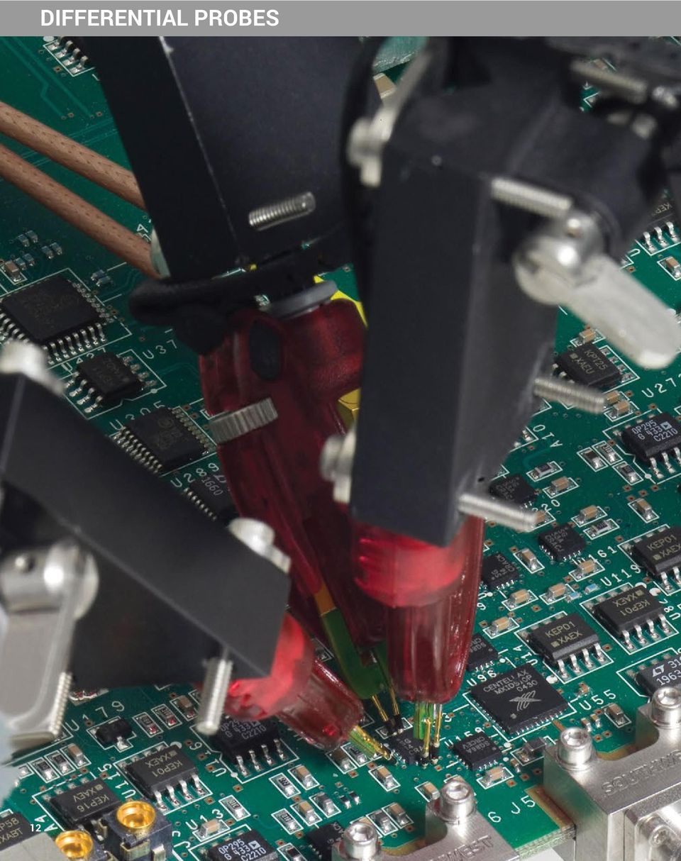
13 DIFFERENTIAL PROBES Differential active probes are like two probes in one. Instead of measuring a test point in relation to a ground point (like single-ended active probes), differential probes measure the difference in voltage of a test point in relation to another test point. Teledyne LeCroy Differential Probe Model Numbers: 1.5 GHz ZD200 ZD500 ZD1000 ZD1500 AP033 4 GHz - 6 GHz D410-PS D420-PS D400A-AT D610-PS D620-PS D600A-AT 8 GHz - 13 GHz D830-PS D1030-PS D1330-PS 13 GHz - 25 GHz D1305-PS D1605-PS D2005-PS D2505-PS Opposite page: WaveLink High Bandwidth Differential Probing System (13 GHz 25 GHz) 13

14 1.5 GHz DIFFERENTIAL PROBES The ZD Series probes provide wide dynamic range, excellent noise and loading performance and an extensive set of probe tips, leads, and ground accessories to handle a wide range of probing scenarios. The low 1 pf capacitance means this probe is ideal for all frequencies. The ZD Series differential probes provide full system bandwidth for all Teledyne LeCroy Oscilloscopes 1.5 GHz and lower. Teledyne LeCroy 1.5 GHz Differential Probe Model Numbers: ZD200 ZD500 ZD1000 ZD1500 AP033 Fully Integrated With the ProBus interface, the ZD500, 1000, and 1500 become an integral part of the oscilloscope. All probe gain and offset controls are transparent to the user, making it easier to probe the circuit without concern for which gain setting to choose. When used with a Teledyne LeCroy digital oscilloscope, no external power supply is required. Wide Dynamic Range The ZD500, 1000, 1500 probes provide transparent probe attenuation so signals are always optimized for the display. The differential range is 18 Vp-p with a differential offset of ±8V and common mode range of ±10 V, making these probes versatile for every probing application. Wide Applications The wide dynamic range of 16 Vp-p and offset range of ±8V suit this probe to a wide range of applications and signal types. The ZD differential probes are ideally suited for Automotive, Serial Data, power, and general purpose use. Specifications ZD200 ZD500 ZD1000 ZD1500 Electrical Characteristics Bandwidth (Warranted) 200 MHz 500 MHz 1000 MHz 1500 MHz Bandwidth (Typical) MHz 1200 MHz 1700 MHz Risetime 10 90% (Typical) 1.75 ns 650 ps 375 ps 270 ps Risetime 20 80% (Typical) ps 280 ps 200 ps LF Attenuation Accuracy (Warranted) 1% 2% Zero Offset (Typical) - 5 mv (within 15 minutes after autozero) System Noise (Typical) mvrms 1.75 mvrms Probe Noise Density (Typical) 3 mv rms 38 nv/rt (Hz) Input Differential Range (Nominal) ± 20 V ±8 V (16 Vp-p) Differential Offset Range (Nominal) - ±18 V Offset Gain Accuracy (Typical) - 2% Common Mode Range (Nominal) ± 60 V ±10 V Maximum Non-destruct Voltage - 30 V (Nominal) CMRR (Typical) DC Input Resistance (Nominal) Differential Input Capacitance (Typical) Hz 50 db@10 MHz 60 db 50/60 Hz 30 db 20 MHz 25 db 500 MHz 60 db 50/60 Hz 30 db 20 MHz MHz 50 kω (Common Mode) 120 kω (Differential Mode) 250 kω (Common Mode) 1 MΩ (Differential Mode) 3.5 pf < 1.0 pf 60 db 50/60 Hz 30 db 20 MHz MHz 14

15 1.5 GHz DIFFERENTIAL PROBES Ordering Information Product Description Product Code 200 MHz, 3.5 pf, 1 MΩ Active Differential Probe ZD200 PACC-MS MHz, 1.0 pf Active Differential Probe, ±8 V Hands Free ZD500 Probe Holder 1 GHz, 1.0 pf Active Differential Probe, ±8 V ZD GHz, 1.0 pf Active Differential Probe, ±8 V ZD1500 ZD1500 / ZD1000 / ZD500 Probe PCF200 Probe Calibration Fixture PCF200 Probe Calibration Fixture PACC-MS001 Hands Free Probe Holder ZD1500 / ZD1000 / ZD500 Probe PCF200 Probe Calibration Fixture PACC-ZD001 Y Lead Adapter PACC-ZD002 Solder-In-Lead Qty: 2 PACC-ZD003 Spring-loaded Ground (Long) Qty: 2 PACC-ZD004 Tip Saver Qty: 2 PACC-ZD005 Swivel Tip Adapter PACC-ZD006 Small IC Adapter Qty: 2 PACC-PT001 Straight Tip Qty: 4 PACC-CD008 Spring-loaded Ground (Short) Qty: 2 PACC-LD003 Right Angle Connector (Short) Qty: 2 PK006-4 Micro-Grabber Qty: 2 PACC-CL001 Mini-Grabber Qty: 2 PACC-LD004 Right Angle Connector (long) Qty: 2 PACC-LD004 Right Angle Connector (long) Qty: 2 AP033 PACC-ZD003 PACC-ZD004 Tip Saver Qty: 2 PACC-ZD005 Swivel Tip Adapter PACC-ZD006 Small IC Adapter Qty: 2 Spring-loaded PK006-4 PACC-CL001 Ground (Long) High Micro-Grabber bandwidth, Mini-Grabber excellent common-mode Qty: 2 rejection ratio Qty: 2 Qty: 2 (CMRR) and low noise make these active differential PACC-ZD001 PACC-ZD002 Y Lead Solder-In-Lead Adapter Qty: 2 probes ideal for applications such as disk drive design and failure analysis, as well as wireless and data communication design. PACC-PT001 Straight Tip Qty: 4 PACC-CD008 Spring-loaded Ground (Short) Qty: 2 Specifications Bandwidth Gain DC Accuracy PACC-LD003 Right Angle Connector (Short) Qty: 2 Input Resistance PACC-LD004 Right Angle Connector (long) Qty: 2 Ordering Information PK006-4 Micro-Grabber Qty: 2 PACC-CL001 Mini-Grabber Qty: MHz x10, x1, 10 ( 100 with plug-on 10 attenuator) 1% in x1 without external attenuator 1 MΩ each input to ground 2 MΩ differential between inputs Differential Mode Range ±400 mv (x1) ±40 mv (x10) ±4 V ( 10) ±40 V ( 100) Offset Range ±400 mv (x1, x10) ±4 V (±10) ±40 V (±100) Common-Mode Range ±42 V peak (±10) +4.2 V peak (±100) CMRR 70 Hz 10,000:1 (80 db) 100 khz 10,000:1 (80 db) 1 MHz 1000:1 (60 db) 10 MHz 100:1 (40 db) 250 MHz 5:1 (14 db) Product Description Product Code 500 MHz Differential Probe AP033 15
 Qty: 2 PACC-ZD004 Tip Saver Qty: 2 PACC-ZD005 Swivel Tip")
16 4 GHz - 6 GHz DIFFERENTIAL PROBES WaveLink probes provide industry leading technology for wideband signal connection to test instruments. The first differential probes to employ SiGe technology, they deliver full system bandwidth when used with oscilloscopes up to 6 GHz. WaveLink probes: Maintain good loading characteristics across the frequency span Optimized for gain, noise and bandwidth for optimal performance Offer broad range of dynamic range and noise over gain settings by incorporating automatic probe attenuation changes Teledyne LeCroy 4 GHz - 6 GHz Differential Probe Model Numbers: D410-PS D420-PS D400A-AT D610-PS D620-PS D600A-AT WaveLink is the first differential probe to use a unique calibration process to achieve superb waveform fidelity for routine voltage measurements. Calibration coefficients fine tune the frequency response of each WaveLink probe and are individually determined during factory calibration and programmed into the probe. The oscilloscopes read this data and use it to digitally compensate the entire system response for superior fidelity. WL-PLINK-CASE ProLink WL-PBUS-CASE ProBus D610 6 GHz D620 6 GHz D410 4 GHz D420 4 GHz D600A-AT D400A-AT Dx10-HITEMP (OPTIONAL) Dx10-SP Dx10-QC Dx10-SI Dx10-PT-KIT (Included in Dx10-PS) Dx20-HITEMP (OPTIONAL) Dx20-SP Dx20-QC Dx20-SI Dx20-PT-KIT (Included in Dx20-PS) 16

17 4 GHz - 6 GHz DIFFERENTIAL PROBES Bandwidth* (Probe Only, Guaranteed) (System Bandwidth, Typical) Rise Time* (10 90%) Rise Time* (20 80%) Noise (System) D610, D610-PS D620, D620-PS D410, D410-PS D420, D420-PS D600A-AT D400A-AT Dx10-SI and Dx20-SI and Dx10-SI, Dx10-HiTemp, Dx20-SI, Dx20-HiTemp, 6 GHz 4 GHz Dx10-PT Tips Dx20-PT Tips Dx10-QC and Dx10-PT Tips Dx20-QC and Dx20-PT Tips 6 GHz 6 GHz 4 GHz 4 GHz Dx10-HiTemp 5 GHz Dx10-QC Tip 4 GHz Dx10-SP Tip 3 GHz Dx10-SI and Dx10-PT Tips 75 ps (typical) Dx10-HiTemp 90 ps (typical) Dx10-QC Tip ps (typical) Dx10-SP Tip 150 ps (typical) Dx10-SI and Dx10-PT Tips 56 ps (typical) Dx10-HiTemp 67.5 ps (typical) Dx10-QC Tip 92 ps (typical) Dx10-SP Tip 113 ps (typical) <36 nv/ Hz (2.8 mv rms ) (typical) Referred to input, 6 GHz bandwidth Dx20-HiTemp 5 GHz Dx20-QC Tip 4 GHz Dx20-SP Tip 3 GHz Dx20-SI and Dx20-PT Tips 75 ps (typical) Dx20-HiTemp 90 ps (typical) Dx20-QC Tip ps (typical) Dx20-SP Tip 150 ps (typical) Dx20-SI and Dx20-PT Tips 56 ps (typical) Dx20-HiTemp 67.5 ps (typical) Dx20-QC Tip 92 ps (typical) Dx20-SP Tip 113 ps (typical) <61 nv/ Hz (4.8 mv rms ) (typical) Referred to input, 6 GHz bandwidth Dx10-SP Tip 3 GHz Dx10-SI, Dx10-HiTemp, and Dx10-PT Tips 112 ps (typical) Dx10-QC Tip ps (typical) Dx10-SP Tip 150 ps (typical) Dx10-SI, Dx10-HiTemp, and Dx10-PT Tips 84 ps (typical) Dx10-QC Tip 92 ps (typical) Dx10-SP Tip 113 ps (typical) <36 nv/ Hz (2.3 mv rms ) (typical) Referred to input, 4 GHz bandwidth Dx20-SP Tip 3 GHz Dx20-SI, Dx20-HiTemp, and Dx20-PT Tips 112 ps (typical) Dx20-QC Tip ps (typical) Dx20-SP Tip 150 ps (typical) Dx20-SI, Dx20-HiTemp, and Dx20-PT Tips 84 ps (typical) Dx20-QC Tip 92 ps (typical) Dx20-SP Tip 113 ps (typical) <67 nv/ Hz (4.3 mv rms ) (typical) Referred to input, 4 GHz bandwidth <75 ps (typical) <112 ps (typical) 56 ps (typical) 84 ps (typical) <74 nv/ Hz (5.8 mv rms ) (typical) Referred to input, 6 GHz bandwidth <74 nv/ Hz (4.1 mv rms ) (typical) Referred to input, 4 GHz bandwidth Input Input Dynamic Range (Nominal) 2.5V pk-pk, ±1.25V 5V pk-pk, ±2.5V 2.5V pk-pk, ±1.25V 5V pk-pk, ±2.5V 4.8V pk-pk, ±2.4V Input Common Mode Voltage Range (Nominal) ±4 V ±2.4 Vmax Input Offset Voltage Range ±3 V Differential (nominal) n/a Non-destructive Input Range (Nominal) ±20 V ±18 V Attenuation 1.7X / 1.0X (nominal) 3.2X / 1.9X (nominal) 1.7X / 1.0X (nominal) 3.2X / 1.9X (nominal) 2.5X DC Input Resistance (Nominal) 100 kω Differential 50 kω Common Mode 4 kω Differential 2 kω Common Mode Impedance (Zmin, Typical) Dx10-SI Lead, Dx10-HiTemp >175 Ω Differential Dx10-PT Tip >175 Ω Differential Dx10-QC Tip >125 Ω Differential Dx10-SP Tip >40 Ω Differential Dx20-SI Lead, Dx20-HiTemp >250 Ω Differential Dx20-PT Tip >175 Ω Differential Dx20-QC Tip >125 Ω Differential Dx20-SP Tip >40 Ω Differential Dx10-SI Lead, Dx10-HiTemp >200 Ω Differential Dx10-PT Tip >175 Ω Differential Dx10-QC Tip >100 Ω Differential Dx10-SP Tip >40 Ω Differential * All bandwidth and rise time measurements are made with an oscilloscope bandwidth greater or equal to the probe bandwidth Through entire frequency range Dx20-SI Lead, Dx20-HiTemp >350 Ω Differential Dx20-PT Tip >175 Ω Differential Dx20-QC Tip >100 Ω Differential Dx20-SP Tip >40 Ω Differential >200 Ω Differential >450 Ω Differential through entire frequency range Product Description Complete Probe Systems 4 GHz Complete Probe System with Dx10-SI Solder-In Tip (Qty. 1), Dx10-SP Square Pin (Qty. 1), Dx10-QC Quick Connect (Qty. 1), and Dx10-PT-KIT Positioner Tip Browser (Qty. 1) 4 GHz Complete Probe System with Dx20-SI Solder-In Tip (Qty. 1), Dx20-SP Square Pin (Qty. 1), Dx20-QC Quick Connect (Qty. 1), and Dx20-PT-KIT Positioner Tip Browser (Qty. 1) 6 GHz Complete Probe System with Dx10-SI Solder-In Tip (Qty. 1), Dx10-SP Square Pin (Qty. 1), Dx10-QC Quick Connect (Qty. 1), and Dx10-PT-KIT Positioner Tip Browser (Qty. 1) 6 GHz Complete Probe System with Dx20-SI Solder-In Tip (Qty. 1), Dx20-SP Square Pin (Qty. 1), Dx20-QC Quick Connect (Qty. 1), and Dx20-PT-KIT Positioner Tip Browser (Qty. 1) Amplifier and Probe Tip Modules WaveLink D410 4 GHz/2.5Vp-p Differential Probe Amplifier with Dx10-SI Solder-In Tip (Qty. 1), Dx10-SP Square Pin (Qty. 1), and Dx10-QC Quick Connect (Qty. 1) WaveLink D420 4 GHz/5Vp-p Differential Probe Amplifier with Dx20-SI Solder-In Tip (Qty. 1), Dx20-SP Square Pin (Qty. 1), and Dx20-QC Quick Connect (Qty. 1) WaveLink D610 6 GHz/2.5Vp-p Differential Probe Amplifier with Dx10-SI Solder-In Tip (Qty. 1), Dx10-SP Square Pin (Qty. 1), and Dx10-QC Quick Connect (Qty. 1) WaveLink D620 6 GHz/5Vp-p Differential Probe Amplifier with Dx20-SI Solder-In Tip (Qty. 1), Dx20-SP Square Pin (Qty. 1), Dx20- QC Quick Connect (Qty. 1) Product Code D410-PS D420-PS D610-PS D620-PS D410 D420 D610 D620 Product Description Amplifier and Probe Tip Modules (cont d) WaveLink D300A-AT 4 GHz/4.8Vp-p Differential Amplifier Module with Adjustable Tip WaveLink D600A-AT 6 GHz/4.8Vp-p Differential Amplifier Module with Adjustable Tip Positioner Tip (Browser) Kits WaveLink Dx10-PT Adjustable Positioner Tip Kit. For use with Dx10 amplifiers. WaveLink Dx20-PT Adjustable Positioner Tip Kit. For use with Dx20 amplifiers. Probe Platform/Cable Assemblies and Adapters WaveLink ProLink Platform/Cable Assembly Kit with complete soft carrying case for all probe items. WaveLink ProBus Platform/Cable Assembly Kit with complete soft carrying case for all probe items. Hi-Temp Leads WaveLink Temperature Extension Cables for Dx10. Includes set of Matched 30" High Temperature Cables (Qty. 1) and solder-in lead set (Qty. 1) WaveLink Temperature Extension Cables for Dx20. Includes set of Matched 30" High Temperature Cables (Qty. 1) and solder-in lead set (Qty. 1) Product Code D400A-AT D600A-AT Dx10-PT-KIT Dx20-PT-KIT WL-PLINK-CASE WL-PBUS-CASE Dx10-HiTemp Dx20-HiTemp 17
 Dx10-SP Tip 150 ps (typical) Dx10-SI and Dx10-PT Tips 56 ps (typical) Dx10-HiTemp 67.5 ps (typical) Dx10-QC Tip 92 ps (typical) Dx10-SP Tip 113 ps (typical) <36 nv/ Hz (2.")
18 8 GHz - 13 GHz DIFFERENTIAL PROBES General Purpose Probe with Range of Capabilities Teledyne LeCroy s WaveLink 8-13 GHz Differential Probes are a medium bandwidth, general purpose probing solution with high input dynamic range and offset range capability. These probes support solder-in, positioner (browser), square pin and SMA/SMP cabled tip/lead connections. The range of capabilities is ideal for a variety of high speed DDR signals where high dynamic range and large offset requirements are common. Teledyne LeCroy 8 GHz - 13 GHz Differential Probe Model Numbers: D830-PS D1030-PS FOR D1330-PS DATASHEET Features and Benefits Choice of 8, 10, or 13 GHz bandwidth models 3.5 V pk-pk dynamic range ±4 V offset range Ideal for DDR3, DDR4, LPDDR3 Deluxe soft carrying case Wide variety of tips and leads Solder-In Lead Positioner (Browser) Tip SMA/SMP Lead Square Pin Lead SMA/SMP lead set accessory does not require purchase of a different amplifier LabMaster 9 Zi-A/10 Zi WaveMaster/SDA/DDA 8 Zi/Zi-A WavePro/SDA/DDA 7 Zi/Zi-A WL-PLINK-CASE Platform/Cable Assembly (Included in Dxx30-PS) D830 8GHz Differential Amplifier D GHz Differential Amplifier D GHz Differential Amplifier Dxx30-SMA-SMP SMA/SMP Lead Set Dxx30-PT Positioner Tip Browser (Included in Dxx30-PS) Dxx30-SI Solder-In Lead (Qty. 2) Dxx30-SP Square Pin 18

19 8 GHz - 13 GHz DIFFERENTIAL PROBES Bandwidth Rise Time (10 90%) Rise Time (20 80%) Noise (Probe) Noise (System) Input Input Dynamic Range Input Common Mode Voltage Range Input Offset Voltage Range Non-destructive Input Range Attenuation DC Input Resistance (Nominal) Impedance (Zmin, Typical) Impedance (Mid-Band, Typical) D830, D830-PS D1030, D1030-PS D1330, D1330-PS Dxx30-SI, Dxx30-SMA-SMP, and Dxx30-SI and Dxx30-SMA-SMP Tips Dxx30-PT Tips 13 GHz (probe only, guaranteed) 10 GHz (probe only, guaranteed) 13 GHz (system bandwidth, 10 GHz (system bandwidth, when used with 813Zi/Zi-A, typical) when used with 813Zi/Zi-A, typical) Dxx30-SI, Dxx30-SMA-SMP, and Dxx30-PT Tips 8 GHz (probe only, guaranteed) 8 GHz (system bandwidth, when used with 808Zi/Zi-A, typical) Dxx30-SP Tip 3 GHz (probe only, guaranteed) 3 GHz (system bandwidth, when used with 808Zi/Zi-A, typical) Dxx30-SI, Dxx30-SMA-SMP, and Dxx30-PT Tips 50 ps (typical) System rise time measured with 8 GHz oscilloscope Dxx30-SP Tip 132 ps (typical) System rise time measured with 8 GHz oscilloscope Dxx30-SI, Dxx30-SMA-SMP, and Dxx30-PT Tips 37.5 ps (typical) System rise time measured with 8 GHz oscilloscope Dxx30-SP Tip 100 ps (typical) System rise time measured with 8 GHz oscilloscope <48 nv/ Hz (4.3 mvrms) (typical) Referred to input, 8 GHz bandwidth. <52 nv/ Hz (4.6 mvrms) (typical) Referred to input, 8 GHz bandwidth. Dxx30-SP Tip 3 GHz (probe only, guaranteed) 3 GHz (system bandwidth, when used with 813Zi/Zi-A, typical) Dxx30-SI, Dxx30-SMA-SMP, and Dxx30-PT Tips 40 ps (typical) System rise time measured with 13 GHz oscilloscope Dxx30-SP Tip 132 ps (typical) System rise time measured with 13 GHz oscilloscope Dxx30-SI, Dxx30-SMA-SMP, and Dxx30-PT Tips 30 ps (typical) System rise time measured with 13 GHz oscilloscope Dxx30-SP Tip 100 ps (typical) System rise time measured with 13 GHz oscilloscope <48 nv/ Hz (4.8 mvrms) (typical) Referred to input, 10 GHz bandwidth. <52 nv/ Hz (5.2 mvrms) (typical) Referred to input, 10 GHz bandwidth. Dxx30-PT Tip 10 GHz (probe only, guaranteed) 10 GHz (system bandwidth, when used with 813Zi/Zi-A, typical) Dxx30-SP Tip 3 GHz (probe only, guaranteed) 3 GHz (system bandwidth, when used with 813Zi/Zi-A, typical) Dxx30-SI and Dxx30-SMA-SMP Tips 35 ps (typical) System rise time measured with 13 GHz oscilloscope Dxx30-PT Tip 40 ps (typical) System rise time measured with 13 GHz oscilloscope Dxx30-SP Tip 132 ps (typical) System rise time measured with 13 GHz oscilloscope Dxx30-SI and Dxx30-SMA-SMP Tips 26 ps (typical) System rise time measured with 13 GHz oscilloscope Dxx30-PT Tip 30 ps (typical) System rise time measured with 13 GHz oscilloscope Dxx30-SP Tip 100 ps (typical) System rise time measured with 13 GHz oscilloscope <48 nv/ Hz (5.5 mvrms) (typical) Referred to input, 13 GHz bandwidth. <52nV/ Hz (5.9 mvrms) (typical) Referred to input, 13 GHz bandwidth. 3.5Vpk-pk, ±1.75V (nominal) ±5 V (nominal) ±4 V Differential (nominal) ±15 V (nominal) 3.75x (nominal) 200 kω Differential 50 kω Common mode >250 Ω Differential through entire frequency range using SI tip Dxx30-SI Lead 470 Ω at 4 GHz, 320 Ω at 6 GHz, 260 Ω at 8 GHz, 250 Ω at 9 GHz, 260 Ω at 10 GHz, 350 Ω at 13 GHz Dxx30-PT Tip 155 Ω at 4 GHz, 210 Ω at 6 GHz, 140 Ω at 8 GHz, 80 Ω at 9 GHz, 40 Ω at 10 GHz Product Description Complete Probe Systems 8 GHz Complete Probe System with Dxx30-SI Solder-In Tip (Qty. 2), Dxx30-SP Square Pin (Qty. 1), and Dxx30-PT-KIT Positioner Tip Browser (Qty. 1) 10 GHz Complete Probe System with Dxx30-SI Solder-In Tip (Qty. 2), Dxx30-SP Square Pin (Qty. 1), and Dxx30-PT-KIT Positioner Tip Browser (Qty. 1) 13 GHz Complete Probe System with Dxx30-SI Solder-In Tip (Qty. 2), Dxx30-SP Square Pin (Qty. 1), and Dxx30-PT-KIT Positioner Tip Browser (Qty. 1) Amplifier and Probe Tip Modules WaveLink D830 8 GHz/3.5V p-p Differential Probe Amplifier with Dxx30-SI Solder-In Tip (Qty. 2) and Dxx30-SP Square Pin (Qty. 1) WaveLink D GHz/3.5V p-p Differential Probe Amplifier with Dxx30-SI Solder-In Tip (Qty. 2) and Dxx30-SP Square Pin (Qty. 1) WaveLink D GHz/3.5V p-p Differential Probe Amplifier with Dxx30-SI Solder-In Tip (Qty. 2) and Dxx30-SP Square Pin (Qty. 1) Product Code D830-PS D1030-PS D1330-PS D830 D1030 D1330 Product Description Positioner Tip (Browser) Kits WaveLink Dxx30-PT (up to 10 GHz rating) Adjustable Positioner Tip Kit. For use with Dxx30 amplifiers. Probe Platform/Cable Assemblies and Adapters WaveLink ProLink Platform/Cable Assembly Kit with complete soft carrying case for all probe items. SMA/SMP Lead Set Lead set consisting of WaveLink Dxx30-SMA-SMP-LEADS for use with Dxx30 amplifiers. Accessories Cascade Microtech EZ-Probe Positioner Probe Deskew and Calibration Test Fixture Calibration Options NIST Calibration for D830. Includes test data. NIST Calibration for D1030. Includes test data. NIST Calibration for D1330. Includes test data. Product Code Dxx30-PT-KIT WL-PLINK-CASE Dxx30-SMA-SMP-LEADS EZ PROBE TF-DSQ D830-CCNIST D1030-CCNIST D1330-CCNIST 19
 when used with 813Zi/Zi-A, typical) Dxx30-SI, Dxx30-SMA-SMP, and Dxx30-PT Tips 8 GHz (probe only, guaranteed) 8 GHz (system bandwidth, when used with 808Zi/Zi-A, typical) Dxx30-SP Tip 3 GHz")
20 13 GHz - 25 GHz DIFFERENTIAL PROBES Ultra-wideband Architecture for Superior Signal Fidelity Teledyne LeCroy s WaveLink high bandwidth differential probes utilize advanced differential traveling wave (distributed) amplifier architecture to achieve superior high frequency true analog broadband performance. Traveling wave (distributed) amplifiers are commonly used in ultra high frequency broadband amplifiers. This multi-stage amplifier architecture maximizes gain per stage and minimizes probe attenuation, which provides very low probe noise and fast rise times. Teledyne LeCroy 13 GHz - 25 GHz Differential Probe Model Numbers: D1305-A-PS D1605-A-PS D2005-A-PS D2505-A-PS Features & Benefits Up to 25 GHz bandwidth (probe + oscilloscope) System rise time as fast as 13 ps (20 80%) 25 GHz Solder-in solution 22 GHz ultra-compact browser tip Superior probe impedance minimizes AC loading on device under test (DUT) Carbon-composite browser tips optimize signal fidelity and minimize loading Probe noise as low as 14 nv/ Hz (1.6 mv rms) Low probe attenuation Large operating voltage range ±4 V common mode range ±2.5 V offset range 2.0 V pk-pk dynamic range Long length Solder-In tip with field replaceable resistors LabMaster 10 Zi LabMaster 9 Zi-A WaveMaster 8 Zi/Zi-A SDA11000 SDA13000 SDA18000 WL-PLINK-A Platform/Cable Assembly: (included in D1x05-A-PS) WL-2.92MM Platform/Cable Assembly (included in D2x05-A-PS) LPA-2.92 LPA 2.92 to ProLink Adapter: D1305-A 13 GHz D1605-A 16 GHz D2005-A 20 GHz D2505-A 25 GHz Differential Amplifier Dxx05-SI Solder-In Lead Dxx05-PT Positioner Tip Browser 20

21 13 GHz - 25 GHz DIFFERENTIAL PROBES Bandwidth Rise Time (10 90%) Rise Time (20 80%) D1305-A, D1305-A-PS D1605-A, D1605-A-PS D2005-A, D2005-A-PS D2505-A, D2505-A-PS Dxx05-SI and Dxx05-PT Tips Dxx05-SI and Dxx05-PT Tips Dxx05-SI and Dxx05-PT Tips Dxx05-SI Lead 13 GHz (probe only, guaranteed) 16 GHz (probe only, guaranteed) 20 GHz (probe only, guaranteed) 25 GHz (probe only, guaranteed) 13 GHz (system bandwidth, 16 GHz (system bandwidth, 20 GHz (system bandwidth, 25 GHz (system bandwidth, when used with 813Zi, typical) when used with 816Zi, typical) when used with 820Zi, typical) when used with 825Zi, typical) Dxx05-SI and Dxx05-PT Tips 32.5 ps (typical) System rise time measured with 13 GHz oscilloscope) Dxx05-SI and Dxx05-PT Tips 24.5 ps (typical) System rise time measured with 13 GHz oscilloscope Noise (Probe) < 14 nv/ Hz (1.6 mv rms ) (typical) Referred to input, 13 GHz bandwidth Noise (System) < 23 nv/ Hz (2.7 mv rms ) (typical) Referred to input, 13 GHz bandwidth Input Input Dynamic Range Input Common Mode Voltage Range Input Offset Voltage Range Non-destructive Input Range Dxx05-SI and Dxx05-PT Tips 28 ps (typical) System rise time, measured with 16 GHz oscilloscope Dxx05-SI and Dxx05-PT Tips 21 ps (typical) System rise time measured with 16 GHz oscilloscope < 14 nv/ Hz (1.8 mv rms ) (typical) Referred to input, 16 GHz bandwidth < 23 nv/ Hz (2.9 mvrms) (typical) Referred to input, 16 GHz bandwidth Dxx05-SI and Dxx05-PT Tips 20 ps (typical) System rise time measured with 20 GHz oscilloscope Dxx05-SI and Dxx05-PT Tips 15 ps (typical) System rise time measured with 20 GHz oscilloscope < 18 nv/ Hz (2.5 mv rms ) (typical) Referred to input, 20 GHz bandwidth < 28 nv/ Hz (4.0 mv rms ) (typical) Referred to input, 20 GHz bandwidth 2.0 V pk-pk, (±1.0 V) (nominal) ±4 V (nominal) ±2.5 V Differential (nominal) ±10 V (nominal) Attenuation 3.5x (nominal) 4.5x (nominal) DC Input Resistance (Nominal) 1.1 kω Differential 100 kω Common mode Impedance (Zmin, typical) Dxx05-SI Lead Dxx05-SI Lead Dxx05-SI Lead > 300 Ω Differential through > 300 Ω Differential through > 230 Ω Differential through entire frequency range entire frequency range entire frequency range Impedance (mid-band, typical) Dxx05-PT Tip >160 Ω Differential through entire frequency range Dxx05-PT Tip >160 Ω Differential through entire frequency range Dxx05-PT Tip >160 Ω Differential through entire frequency range Dxx05-SI Lead: 300 Ω at 6 GHz, 525 Ω at 13 GHz, 600 Ω at 16 GHz, 300 Ω at 20 GHz, 120 Ω at 25 GHz Dxx05-PT Tip: 160 Ω at 6 GHz, 450 Ω at 13 GHz, 240 Ω at 16 GHz, 210 Ω at 20 GHz Dxx05-PT Tip 22 GHz (system bandwidth, when used with 825Zi, typical) 20 GHz (probe only, guaranteed) Dxx05-SI Lead 17.5 ps (typical) System rise time measured with 25 GHz oscilloscope Dxx05-PT Tip 19 ps (typical) System rise time measured with 25 GHz oscilloscope Dxx05-SI Lead 13 ps (typical) System rise time measured with 25 GHz oscilloscope Dxx05-PT Tip 14 ps (typical) System rise time measured with 25 GHz oscilloscope < 18 nv/ Hz (2.8 mv rms ) (typical) Referred to input, 25 GHz bandwidth < 28 nv/ Hz (4.5 mv rms ) (typical) Referred to input, 25 GHz bandwidth Dxx05-SI Lead > 120 Ω Differential through entire frequency range Dxx05-PT Tip >160 Ω Differential through entire frequency range Product Description Complete Probe Systems 13 GHz Complete Probe System with Solder-In Tip (13 GHz) and Positioner Tip Browser (13 GHz) 16 GHz Complete Probe System with Solder-In Tip (16 GHz) and Positioner Tip Browser (16 GHz) 20 GHz Complete Probe System with Solder-In Tip (20 GHz) and Positioner Tip Browser (20 GHz) 25 GHz Complete Probe System with Solder-In Tip (25 GHz) and Positioner Tip Browser (22 GHz) Amplifier and Probe Tip Modules WaveLink D GHz/1.6 V pk-pk Differential Probe Amplifier with Dxx05-SI Solder-In Tip (Qty. 2) WaveLink D GHz/1.6 V pk-pk Differential Probe Amplifier with Dxx05-SI Solder-In Tip (Qty. 2) WaveLink D GHz/1.6 V pk-pk Differential Probe Amplifier with Dxx05-SI Solder-In Tip (Qty. 2) WaveLink D GHz/1.6 V pk-p Differential Probe Amplifier with Dxx05-SI Solder-In Tip (Qty. 2) Positioner Tip (Browser) Kits WaveLink Dxx05-PT (Up to 22 GHz Rating) Adjustable Positioner Tip Kit. For use with Dxx05 Amplifiers Probe Platform/Cable Assemblies and Adapters WaveLink ProLink Platform/Cable Assembly Kit for 13 GHz WaveLink Probes WaveLink 2.92 mm Platform/Cable Assembly Kit for 20 GHz WaveLink Probes ProLink to 2.92 mm Adapter with Probe Power and Communication Pass Through Product Code D1305-A-PS D1605-A-PS D2005-A-PS D2505-A-PS D1305-A D1605-A D2005-A D2505-A Dxx05-PT-KIT WL-PLINK-A-CASE WL-2.92MM-CASE LPA-2.92 Product Description Accessories Cascade Microtech EZ-Probe Positioner Probe Deskew and Calibration Test Fixture Calibration Options NIST Calibration for D1305. Includes Test Data NIST Calibration for D1605. Includes Test Data NIST Calibration for D2005. Includes Test Data NIST Calibration for D2505. Includes Test Data Replacement Parts Replacement Dxx05-SI GHz Solder-In Lead with Qty. 5 Spare Resistors Replacement SI Resistor Kit for Dxx05-SI Solder-In Tip Replacement Dxx05-PT Positioner Tip Qty. 4 Replacement Carbon Composite Pogo-pin Tips Replacement Probe Tip Holder Kit Replacement Platform/Cable Assembly Mounting Kit Qty. 1 Package of Black Adhesive Pads (10/pkg.) and Qty. 1 Package of White Adhesive Pads (10/pkg.) Qty. 1 Package of Adhesive Probe Connection Guides (200 individual guides/package) Product Code EZ PROBE TF-DSQ D1305-A-CCNIST D1605-A-CCNIST D2005-A-CCNIST D2505-A-CCNIST Dxx05-SI Dxx05-SI-RESISTORS Dxx05-PT Dxx05-PT-TIPS PK600ST-3 PK600ST-4 Dxx0-PT-TAPE Dxx05-PT-GUIDES 21
22 22 HIGH VOLTAGE DIFFERENTIAL PROBES
23 HIGH VOLTAGE DIFFERENTIAL PROBES Differential active probes are like two probes in one. Instead of measuring a test point in relation to a ground point (like single-ended active probes), differential probes measure the difference in voltage of a test point in relation to another test point. Teledyne LeCroy High Voltage Differential Probe Model Numbers: HVD3102 HVD3106 HVD3106-6M HVD3206 HVD3605 AP031 ADP300 ADP305 Opposite page: HVD3000 Series High Voltage Differential Probes working with an HDO
24 HIGH VOLTAGE DIFFERENTIAL PROBES Teledyne LeCroy High Voltage Differential Probe Model Numbers: HVD3102 HVD3106 HVD3106-6M HVD3206 HVD3605 The HVD3000 series high voltage differential probes provide high CMRR over a broad frequency range to simplify the measurement challenges found in noisy, high common-mode power electronics environments. The probe s design is easy-to-use and enables safe, precise high voltage floating measurements. Key Features 1 kv, 2 kv, 6 kv CAT safety rated models World s only 1500 Vdc safety rated probe per IEC/EN :2015 Widest differential voltage ranges available Exceptional common-mode rejection ratio (CMRR) across a broad frequency range 1% gain accuracy High offset capability at both high and low attenuation AC and DC coupling ProBus active probe interface with automatic scaling Auto-zero capabilities Wide oscilloscope compatibility 24
25 HIGH VOLTAGE DIFFERENTIAL PROBES HVD3102 HVD3102-NOACC HVD3106 HVD3106-NOACC HVD3106-6M HVD3206 HVD3605 Bandwidth 25 MHz 25 MHz 120 MHz 120 MHz 80 MHz 120 MHz 100 MHz Differential Voltage Range 1500 V (DC + peak AC) (2000V maximum typical measurable before saturation) 1500 V (DC + peak AC) (2000V maximum typical measurable before saturation 1500 V (DC + peak AC) (2000V maximum typical measurable before saturation) 1500 V (DC + peak AC) (2000V maximum typical measurable before saturation) 1500 V (DC + peak AC) (2000V maximum typical measurable before saturation) 2000 V (DC + peak AC) 7000 V (DC + peak AC) (7600 V maximum typical measurable before saturation) Max Safe Input Voltage 1000 Vrms CAT III 1000 Vrms CAT III 1000 Vrms CAT III 1000 Vrms CAT III 1000 Vrms CAT III 1000 Vrms CAT III 1500 Vdc CAT III 2000 V (DC + peak AC ) CAT I 8485 V (DC + peak AC) CAT I 6000 Vrms CAT I 1000 Vrms CAT III 1500 Vdc CAT III Gain 1% 1% 1% 1% 1% 1% 1% HVD310X/3106-6M Accuracy High Voltage Cable Length 2 meters 2 meters 2 meters 2 meters 6 meters Differential Probe 2 meters 6 meters Included Tip Accessories Yes No Yes No Yes Yes Yes PK-HVA-01 Safety Alligator 1000 V CAT III PK-HVA-01 Safety Alligator 1000 V CAT III PK-HVA-02 Plunger Pincer 1000 V CAT II PK-HVA-02 Plunger Pincer 1000 V CAT II PK-HVA-03 Plunger Hook 1000 V CAT II PK-HVA-03 Plunger Hook 1000 V CAT II PK-HVA-04 Plunger Alligator 1000 V CAT III PK-HVA-04 Plunger Alligator 1000 V CAT III PK-HVA-05 Spade Terminals (Red/Black) 1000 V CAT III PK-HVA-05 Spade Terminals (Red/Black) 1000 V CAT III PK-HVA-06 6 KV Safety Alligator 6000 V CAT I PK-HVA-06 6 KV Safety Alligator 6000 V CAT I HVD310X/3106-6M High Voltage Differential Probe HVD310X/3106-6M High Voltage Differential Probe PK-HVA-01 Safety Alligator 1000 V CAT III PK-HVA-02 Plunger Pincer 1000 V CAT II PK-HVA-03 Plunger Hook 1000 V CAT II PK-HVA-04 Plunger Alligator 1000 V CAT III PK-HVA-05 Spade Terminals (Red/Black) 1000 V CAT III PK-HVA-06 6 KV Safety Alligator 6000 V CAT I HVD3206/3605 High Voltage Differential Probe PK-HVA-01 Safety Alligator 1000 V CAT III PK-HVA-01 Safety Alligator 1000 V CAT III PK-HVA-02 Plunger Pincer 1000 V CAT II PK-HVA-02 Plunger Pincer 1000 V CAT II PK-HVA-03 Plunger Hook 1000 V CAT II PK-HVA-03 Plunger Hook 1000 V CAT II PK-HVA-04 Plunger Alligator 1000 V CAT III PK-HVA-04 Plunger Alligator 1000 V CAT III PK-HVA-05 Spade Terminals (Red/Black) 1000 V CAT III PK-HVA-05 Spade Terminals (Red/Black) 1000 V CAT III PK-HVA-06 6 KV Safety Alligator 6000 V CAT I PK-HVA-06 6 KV Safety Alligator 6000 V CAT I HVD3206/3605 High Voltage Differential Probe HVD3206/3605 High Voltage Differential Probe PK-HVA-01 Safety Alligator 1000 V CAT III PK-HVA-02 Plunger Pincer 1000 V CAT II PK-HVA-03 Plunger Hook 1000 V CAT II PK-HVA-04 Plunger Alligator 1000 V CAT III PK-HVA-05 Spade Terminals (Red/Black) 1000 V CAT III PK-HVA-06 6 KV Safety Alligator 6000 V CAT I HVD310X-NOACC High Voltage Differential Probe Ordering Information Product Description PK-HVA-01 Safety Alligator 1000 V CAT III PK-HVA-01 Safety Alligator 1000 V CAT III PK-HVA-01 Safety Alligator PK-HVA-02 Plunger Pincer 1000 V CAT II PK-HVA-02 Plunger Pincer 1000 V CAT II PK-HVA-02 Plunger Pincer PK-HVA-03 Plunger Hook 1000 V CAT II PK-HVA-03 Plunger Hook 1000 V CAT II PK-HVA-03 Plunger Hook PK-HVA-04 Plunger Alligator 1000 V CAT III PK-HVA-04 Plunger Alligator 1000 V CAT III PK-HVA-04 Plunger Alligator PK-HVA-05 Spade Terminals (Red/Black) 1000 V CAT III PK-HVA-05 Spade Terminals (Red/Black) 1000 V CAT III PK-HVA-05 Spade Terminals (Red/Black) PK-HVA-06 6 KV Safety Alligator 6000 V CAT I PK-HVA-06 6 KV Safety Alligator 6000 V CAT I PK-HVA-06 6 KV Safety Alligator HVD310X-NOACC High Voltage Differential Probe HVD310X-NOACC High Voltage Differential Probe Product Code 1000 V CAT III 1000 V CAT II 1000 V CAT II 1000 V CAT III 1000 V CAT III 6000 V CAT I 1 kv, 25 MHz High Voltage Differential Probe with 2 m cable HVD kv, 120 MHz High Voltage Differential Probe with 2 m cable HVD kv, 80 MHz High Voltage Differential Probe with 6m cable HVD3106-6M 1 kv, 25 MHz High Voltage Differential Probe with 2 m cable without tip Accessories HVD3102-NOACC 1 kv, 120 MHz High Voltage Differential Probe with 2 m cable without tip Accessories HVD3106-NOACC 2 kv, 120 MHz High Voltage Differential Probe with 2 m cable HVD kv, 100 MHz High Voltage Differential Probe with 6 m cable HVD3605 High Voltage Replacement Accessories Kit (Includes 2 each, 1 Black, 1 Red): PK-HV-001 Safety Alligator Clips, Plunger Pincer Clips, Plunger Hook Clips, Plunger Alligator Clips, Spade Terminals 25
26 HIGH VOLTAGE DIFFERENTIAL PROBES Teledyne LeCroy High Voltage Differential Probe Model Numbers: AP031 ADP300 ADP305 AP031 The AP031 is a low cost, battery operated active differential probe intended for measuring higher voltages. The differential techniques employed permit measurements to be taken at two points in a circuit without reference to the ground, allowing the oscilloscope to be safely grounded without the use of opto-isolators or isolating transformers. Features Safe floating measurements 15 MHz bandwidth 700 V maximum input voltage Works with any 1 MΩ input oscilloscope 26 Specifications Attenuation 10 / 100 Bandwidth 15 MHz Input R 4 MΩ Differential Mode Range ±70 V / ±700 V DC + Peak AC Common Mode Range ±700 V DC + Peak AC CMRR Hz khz Power Requirements: four AA batteries Ordering Information Product Description Product Code 700 V, 15 MHz Differential Probe ( 10, 100) AP031 1,400 V, 20 MHz High-Voltage Differential Probe AP300 1,400 V, 100 MHz High-Voltage Differential Probe AP305
27 HIGH VOLTAGE DIFFERENTIAL PROBES ADP30X ADP30X high-voltage active probes are safe, easy-to-use, and ideally suited for measuring power electronics. The ADP300 is designed for troubleshooting low-frequency power devices and other circuits where the reference potential is elevated from the ground or the location of the ground is unknown. The ADP305 is designed for measuring the high-speed floating voltages found in today s power electronics. Features 20 MHz and 100 MHz bandwidth 1,000 V rms common mode voltage 1,400 V peak differential voltage EN CAT III 80 db CMRR at 50/60 Hz ProBus system Full remote control Specifications Electrical Characteristics Bandwidth 20 MHz (ADP300) 100 MHz (ADP305) Differential Voltage 1,400 V peak Common Mode Voltage 1,000 V rms CAT III Low-Frequency Accuracy (Probe Only) 1% of Reading CMRR 50/60 Hz 80 db (10,000:1) 100 khz 50 db (300:1) Max. Slew Rate (Referenced to Input) 60,000 V/µs (ADP300) 300,000 V/µs (ADP305) AC Noise (Referenced to Input) 50 mv rms Attenuation 100/ 1000 (automatically selected by scope) Input Impedance Between inputs 8 MΩ, 6 pf Each input to ground 4 MΩ, 1 pf Sensitivity 1 V/div to 350 V/div (ADP300) 200 mv/div to 350 V/div (ADP305) Interface ProBus, 1 MΩ* General Characteristics Overall Length Input Connectors Operating Temperature Warranty *Requires AP-1M for oscilloscopes with 50 Ω only inputs 2 m 4 mm Shrouded Banana Plug 0 C to 50 C 1 year 27
28 DIFFERENTIAL AMPLIFIERS 28
29 DIFFERENTIAL AMPLIFIERS Differential amplifiers are intended to act as signal conditioning preamplifiers for oscilloscopes and network and spectrum analyzers, providing differential measurement capability to instruments having only a single-ended input. The -PR2 version of each amplifier is a dual channel unit. The DXC series differential input cables are matched to the characteristics of the amplifier. Teledyne LeCroy Differential Amplifier and Accessory Model Numbers: DA1855A DA1855-PR2 DA1855A-RM DA1855A-PR2-RM DXC5100 DXC100A DXC200 DA101 Opposite page: DA1855A Differential Amplifier working with the HDO6000 oscilloscope for power measurement. 29
30 DIFFERENTIAL AMPLIFIERS Teledyne LeCroy Differential Amplifier and Accessory Model Numbers: DA1855A DA1855-PR2 DA1855A-RM DA1855A-PR2-RM DXC5100 DXC100A DXC200 DA101 DA1855A The DA1855A is a stand-alone, highperformance 100 MHz differential amplifier. It is intended to act as a signal conditioning preamplifier for oscilloscopes, digitizers and spectrum analyzers, providing differential measurement capability to instruments having only a single-ended input. When used with a DA1855A, oscilloscopes can obtain Common Mode Rejection Ratio (CMRR) and overdrive recovery performance levels previously unobtainable. Amplifier gain can be set to 1 or 10 A built-in input attenuator can be separately set to attenuate signals by a factor of 10, providing gains of 10, 1, or 0.1 and common mode dynamic range of ±15.5 V ( 1) or ±155 V ( 10). Optional probes increase the maximum input signal and common mode ranges in proportion to their attenuation ratio but do not exceed their maximum input voltage rating. Effective gain of the DA1855A, including probe attenuation, amplifier gain and attenuator settings, is automatically displayed. The DA1855A features a built-in Precision Voltage Generator (PVG) that can be set to any voltage between ±15.5 V (±10 V in Differential Offset) with up to 100 µv resolution. The PVG s output can be selected as an input to the inverting (-) input of the amplifier for operation as a differential comparator, or applied internally as a true differential offset voltage independent of oscilloscope offset. The differential amplifier is also available in a 2 channel model. In addition, a rackmount is available for each model for easy installation with other instruments. 30
31 DIFFERENTIAL AMPLIFIERS DXC100A 100 or 10 Selectable, 250 MHz Passive Differential Probe Pair DC to 100 MHz Bandwidth with DA1855A DC to 10 MHz Bandwidth with DA1822 Max Input Voltage 500 V Selectable 10 or 100 Attenuation Factor 1.2 m Cable Length DXC200 1, 50 MHz, Passive Differential Probe Pair DC to 50 MHz with DA1855A DC to 10 MHz with DA1822A Max Input Voltage 500 V (Limited to Amplifier Max Input Voltage) x1 Differential Probe Pair 0.7 m Cable Length DXC , 2.5KV Passive High Voltage Probe Pair. Requires DA101 for full performance DA101 10, 1MΩ Passive Attenuator for DXC series probes Ordering Information Product Description Product Code 1 Ch, 100 MHz Differential Amplifier with Precision Voltage Source DA1855A 2 Ch,100 MHz Differential Amplifier with Precision Voltage Source DA1855A-PR2 DA1855A with Rackmount DA1855A-RM DA1855A with Rackmount (must be ordered at time of purchase, no retrofit) DA1855A-PR2-RM 100 or 10 Selectable, 250 MHz Passive Differential Probe Pair DXC100A* 1, 50 MHz Passive Differential Probe Pair DXC200* 100, 250 MHz 2.5 kv, High Voltage Probe Pair (requires DA101 for full performance) DXC-5100* 10 1 MΩ Passive Attenuator for DXC Series Probes DA101* *Must be used with DA Series Differential Amplifiers 31
32 HIGH VOLTAGE PROBES 32
33 HIGH VOLTAGE PROBES High voltage probes are suitable for a wide range of applications where high-voltage measurements must be made safely and accurately. There are several fixed attenuation probes covering a range from 1 kv to 6 kv and varying transient overvoltage ratings. All of these high voltage probes feature a spring loaded probe tip and a variety of standard accessories to make probing high voltages safe and easy. Additionally, all of the high voltage probe have a probe sense pin to automatically configure the oscilloscope for use with the probe. Teledyne LeCroy High Voltage Probe Model Numbers: HVP120 PPE1.2KV PPE2KV PPE4KV PPE5KV PPE6KV Opposite page: PPE Series High Voltage Probe 33
34 HIGH VOLTAGE PROBES Teledyne LeCroy High Voltage Probe Model Number: HVP120 The HVP120 is a high voltage passive probe designed for probing up to 1,000 Vrms and capable of handling up to 6,000 V peak transients. Its fast rise time and excellent frequency response make it suitable for a wide variety of high voltage measurement applications. The HVP120 features a spring loaded probe tip and a variety of standard accessories to make probing high voltages safe and easy. Features 400 MHz probe bandwidth 900 ps rise time 1000 Vrms maximum input Up to 6 kv transient overvoltage Electrical Characteristics Bandwidth 400 MHz Risetime (10% - 90%) 900 ps (typical) Maximum Input Voltage* Measurement Category II 1000 Vrms Measurement Category I 4000V Transient Overvoltage at 1000 Vrms 6000V Transient Overvoltage at 0 Vrms Pollution Degree* 2 Input Capacitance 7.5 pf (typical) Compensation Range 10 pf - 50 pf (typical) Attenuation Ratio 100:1 ± 2% Environmental Temperature (Operating) 0 C to 50 C Temperature (Non-Operating) -40 C to 71 C Humidity (Operating) 80% RH (Non-Condensing) up to 31 C, decreasing linearly to 40% RH at 50 C Altitude (Operating) up to 2,000 m Altitude (Non-Operating) up to 15,000 m 34 General Characteristics Weight (probe) Cable Length Probe Tip Diameter * As defined in IEC g (0.15 lbs) 2 m (6.56 ft) 5 mm (0.20 inches)
35 HIGH VOLTAGE PROBES Amplitude AC rms [V]sinus Typical Voltage Derating HVP120 Measurement Category I 0 100K 1M 10M 100M 1G Frequency [Hz] Peak Pulse [V] HVP120 RMS vs. Peak Pulse Voltage Measurement Category I AC rms or DC [V] Product Description Product Code 400 MHz, High Voltage Passive Probe HVP120 High Voltage Replacement Accessories Kit PK-HV-002 Replacement Accessories One of each of the following accessories are included with the HVP120. Replacement quantities are listed below. Coding Rings (set) 4 Colors (Qty 3 also included standard) Ground Lead 22 cm to 4 mm Banana plug (Qty 1) Solid Tip 0.8 mm (Qty 5) Spring Tip 0.8 mm (Qty 5) BNC Adapter 5.0-L (Qty 1) Insulating Cap 5.0-L (Qty 1) Protection Cap 5.0-L (Qty 1) Sprung Hook 5.0-L (Qty 1) Adjustment Tool T (Qty 1) Flexible Adapter 5.0-L (Qty 1) Safety Alligator Clip red (Qty 1) Ground Lead 22 cm (Qty 1) PK1-5MM-106 PK1-5MM-122 PK1-5MM-125 PK1-5MM-126 PK1-5MM-127 PK1-5MM-128 PK1-5MM-129 PK1-5MM-130 PK1-5MM-131 PK1-5MM-132 PK1-5MM-133 PK1-5MM
36 HIGH VOLTAGE PROBES Teledyne LeCroy High Voltage Probe Model Numbers: PPE1.2KV PPE2KV PPE4KV PPE5KV PPE6KV The PPE series includes four fixed-attenuation probes covering a range from 2 kv to 6 kv, and one switchable probe providing 10/ 100 attenuation for voltage inputs up to 1.2 kv. All fixed-attenuation, standard probes automatically rescale compatible Teledyne LeCroy oscilloscopes for the appropriate attenuation of the probe. Features Safe, accurate high-voltage measurement 1.2 kv to 6 kv High-Voltage Probes Selection Guide Specifications Types Bandwidth Input R Input C Attenuation Maximum Probe Cable (MHz) (Ω) (pf) Voltage Encoding PPE1.2kV* M < 6 10 / V/1.2 kv No 2 m PPE2kV* M < kv Yes 2 m PPE4kV* M < kv Yes 2 m PPE5kV* M < kv Yes 2 m PPE6kV* M < kv Yes 2 m 36
37 HIGH VOLTAGE PROBES Trimming Tool Security Ground Lead Ground Lead (22 cm) Flexible 4 mm Security Adapter BNC Adapter Insulating Tip IC Insulating Tip Straight Tip (0.8 mm) Spring Contact Tip (0.8 mm) Sprung Hook Crocodile Clip (Black) Crocodile Clip (Red) Ordering Information Product Description Product Code 10/ 100; 200/300 MHz; 5 MΩ/50 MΩ High-Voltage Probe, 600 V/1.2 kv max. Voltage DC PPE1.2KV 100; 400 MHz; 50 MΩ High-Voltage Probe, 2 kv max. Voltage DC and Peak AC PPE2KV 100; 400 MHz; 50 MΩ High-Voltage Probe, 4 kv max. Voltage DC and Peak AC PPE4KV 100; 400 MHz; 50 MΩ High-Voltage Probe, 5 kv max. Voltage DC and Peak AC PPE5KV 1000; 400 MHz; 50 MΩ High-Voltage Probe, 6 kv max. Voltage DC and Peak AC PPE6KV Accessory Kit for PPE1.2kV, 2kV, 4kV, 5kV, and 6kV PK103 Sprung Hook (red) PK103-1 Ground Lead (22 cm) PP005-GL22 Crocodile Clip PK30x-2 Probe Tip to BNC Adapter PP005-BNC Spring Tip (0.8 mm) PP005-ST8 Rigid Tip V2A PP005-RT Supplied with probe: * Probe Kit: Trimming tool, ground lead, rigid tip, IC insulator, BNC adapter, tip insulator, spring hook, red crocodile clip. 4 mm safety ground lead, and green/yellow crocodile clip. 37
38 38 OPTICAL PROBES
39 OPTICAL PROBES Teledyne LeCroy s wide-band multi-mode optical-to-electrical converters are designed for measuring optical communications signals. Their broad wavelength range and multi-mode input optics make these devices ideal for applications including Ethernet, Fibre Channel, and ITU telecom standards. Available to support optical data rates up to 11.3 Gb/s with reference receivers, or slightly higher without reference receivers. These wide- band multi-mode optical-to-electrical converters are designed for measuring optical communications signals. They connect to Teledyne LeCroy real-time oscilloscopes and provide capability for physical layer signal assessment using a variety of oscilloscope tools, such as SDAIII- CompleteLinQ Serial Data Eye, Jitter, Noise and Crosstalk Analysis, mask testing, serial triggering and decoding, and other compliance and debug tools. Maximum data rate test capability is > Gb/s with reference receiver, or 12.5 Gb/s without. Teledyne LeCroy Optical Probe Model Numbers: OE695G OE425 OE455 OE525 OE555 Opposite page: OE455 Optical Probe working with a WaveRunner 640 Zi oscilloscope. 39

40 OPTICAL PROBES OE695G Teledyne LeCroy s OE695G wide-band optical-to-electrical converter is ideal for measuring optical datacom and telecom signals with data rates from 622 Mb/s to Gb/s. Connection to a real-time Teledyne LeCroy oscilloscope is through the 2.92mm interface, with a provided adapter to connect to ProLink interfaces. 40 Teledyne LeCroy Optical Probe Model Numbers: OE695G OE425 OE455 OE525 OE555 Features Compatible with Teledyne LeCroy WavePro 7 Zi/Zi-A, WaveMaster 8 Zi/Zi-A, LabMaster 9 Zi-A, and LabMaster 10 Zi oscilloscopes Frequency range DC to 9.5 GHz (electrical, -3 db) Reference receiver support from 8GFC to 10GFC FEC, or Custom (<12.5Gb/s) Full bandwidth mode (no reference receiver applied) 62.5/125 µm multi-mode or single-mode fiber input +7 dbm (5 mw) max peak optical power Low noise (as low as 25 pw/ Hz) Ideal for Eye Mask, Extinction Ratio, and Optical Modulation Amplitude (OMA) testing Specifications Optical Wavelength Range Maximum Modulation Bandwidth Reference Receiver Uncertainty Reference Receiver Settings Noise Equivalent Power Rise Time (10-90%) Connector Type Maximum Optical Linear Input (1 db Compression Point) Maximum Optical Power Conversion Gain (typical) 780 to 1550 nm (calibrated range) 750 to 1650 nm (usable range) DC to GHz (-3 dbe, electrical) DC to GHz (-3 dbo, optical) (Reference Receiver Applied) DC to 9.5 GHz (-3 dbe) DC to 12 GHz (-6 dbe) DC to 17 GHz (-14 dbe) (+/-1 dbe passband variations typical, no Reference Receiver Applied) ±1.6 dbe up to Fref =0.75*bit rate ±4 dbe 2*Fref setting (typical) ±0.85 dbe up to Fref =0.75*bit rate ±4 dbe 2*Fref setting (on matched oscilloscope input channel 4 with 11, 17, 20, 30, 39, 50, 75, 90, or 100 mv/div gain ranges) with purchase of OE695G- REFCAL) 8GFC, OC192/STM64,10GBASE-W,10GBASE-R, 10GFC, ITU-T G.975 FEC, ITU-T G.709 FEC, 10GbE FEC, 10GFC FEC, Custom (622 Mb/s to 12.5 Gb/s), None (Maximum Bandwidth) 25 pw/ 1310 nm (typical) 50 pw/ 850 nm (typical) Average noise spectral density 0-10 GHz using most sensitive vertical scale 33 ps (typical, no reference receiver applied) FC/PC, compatible with 62.5/125 µm Multi-Mode fiber, or mechanically compatible Single-Mode fiber -2 dbm (typical), -3 dbm (minimum) at 1550/1310 nm +4 dbm (typical), +3 dbm (minimum) at 850 nm +7 dbm (5 mw) Peak 0.17 V/mW (785 nm) 0.21 V/mW (850 nm) 0.33 V/mW (1310 nm) 0.33 V/mW (1550 nm)
41 OPTICAL PROBES OE425/OE455/OE525/OE555 The O/E converters contain calibration data that can be used to create optical reference receivers for SONET/SDH (up to OC48/STM16), Fibre Channel, Gigabit Ethernet, and other optical standards. This feature is available when the O/E is used on a supported oscilloscope. The universal reference receiver supports any data rate up to 3 GHz and remains calibrated on any channel of the oscilloscope. Features Frequency range to 5 GHz (6 GHz optical) 62.5 µm or narrower multi-mode or single-mode fiber input Broad wavelength range: nm (OE425, OE525) nm (OE455, OE555) High responsivity Low noise Included Accessories: Multi-mode optical fiber jumper FC-FC FC to ST adapter FC to SC adapter Specifications OE425/OE525 OE455/OE555 Wavelength Range nm nm (0.1 V/mW) nm nm (0.1 V/mW) Conversion Gain 0.5 V/mW 1.1 V/mW Bandwidth 5 GHz (6 GHz optical) 3.5 GHz (4.5 GHz optical) Equivalent Noise 2.2 µw rms 1.0 µw rms Maximum Optical Power 2.2 mw 1.0 mw (at 5% Saturation) Rise Time 90 ps 108 ps Maximum Safe Input 5.5 mw 2.5 mw Temperature Drift db / C db / C Frequency Response Ripple 1.1 db 1.1 db Connector Type FC/PC FC/PC Ordering Information Product Description Optical-to-Electrical Converter, 785 to 1550 nm, 2.92 mm connector with ProLink adapter Optical-to-Electrical Converter, nm ProBus BNC Connector Optical-to-Electrical Converter, nm ProBus BNC Connector Optical-to-Electrical Converter, nm ProLink BMA Connector Optical-to-Electrical Converter, nm ProLink BMA Connector Product Code OE695G OE425 OE455 OE525 OE555 41
42 PASSIVE PROBES 42
43 PASSIVE PROBES Passive probes are the standard probe provided with most oscilloscopes. Typical passive probes provide a 10 attenuation and feature a high input resistance of 10 MΩ. This high input resistance means that passive probes are the ideal tool for low frequency signals since circuit loading at these frequencies is minimized. Passive probes are designed to handle voltages of at least 400 V, some as high as 600 V. Teledyne LeCroy passive probes feature an attenuation sense pin which tells the oscilloscope to scale the waveforms automatically requiring no user input. Teledyne LeCroy Passive Probe Model Numbers: PP006A PP007-WR PP008 PP009 PP010 PP011 PP016 PP017 PP018 PP019 PP020 43
44 PASSIVE PROBES Each passive probe is recommended for a certain oscilloscope, using the right passive probe with the right oscilloscope means that the probe can be properly compensated across the entire bandwidth. Using probes with a different oscilloscope will only let you compensate for low frequencies. Features Bandwidth from 200 MHz to 500 MHz Probe encoding ring for automatic scale factor readout on Teledyne LeCroy oscilloscopes Teledyne LeCroy Passive Probe Model Numbers: PP006A PP007-WR PP008 PP009 PP010 PP011 PP016 PP017 PP018 PP019 PP020 Specifications Types Bandwidth Input R Input C Attenuation Maximum Diameter Voltage PP006A 500 MHz 10 MΩ 12 pf V 5 mm PP007-WR 500 MHz 10 MΩ 9.5 pf V 2.5 mm PP MHz 10 MΩ 9.5 pf V 2.5 mm PP MHz 10 MΩ 9.5 pf V 2.5 mm PP MHz 10 MΩ 9.5 pf V 2.5 mm PP MHz 10 MΩ 9.5 pf V 5 mm PP MHz/ 10 MΩ/ 12 pf/ 10/ 600 V 5 mm 10 MHz 1 MΩ 46 pf 1 PP MHz 10 MΩ 12 pf V 5 mm PP MHz 10 MΩ 10 pf V 5 mm PP MHz 10 MΩ 12 pf V 5 mm PP MHz 10 MΩ 11 pf V 5 mm Ordering Information Product Description Product Code 10, 500 MHz 10 MΩ Passive Probe PP006A 10, 500 MHz 10 MΩ Passive Probe PP007-WR 10, 500 MHz 10 MΩ Passive Probe PP008 10, 500 MHz 10 MΩ Passive Probe PP009 10, 200 MHz 10 MΩ Passive Probe PP010 10, 500 MHz 10 MΩ Passive Probe PP011 10, 300 MHz 10 MΩ Passive Probe PP016 10, 250 MHz 10 MΩ Passive Probe PP017 10, 500 MHz 10 MΩ Passive Probe PP018 10, 200 MHz 10 MΩ Passive Probe PP019 10, 500 MHz 10 MΩ Passive Probe PP020 44
45 PASSIVE PROBES Passive Probe Accessories for PP009, and PP011 Series PK1-5MM-105 IC-Cap 5.0 Insulating Cap PK1-5MM-103 Adjustment Tool PK1-5MM-108 IC-Cap mm pitch; black Protection Cap 5.0 black 1.5 mm PK1-5MM-107 PCB Adapter mm 1.0 mm x 4 K1-5MM-106 Set Coding Rings 3x4 colors PK1-5MM-102 Ground Lead 11 cm PK1-5MM-101 Sprung Hook II 5.0 black PK1-5MM-117 Flexible Adapter 5.0 to 5 mm banana plug PK1-5MM-104 Rigid Tip 0.8 mm PK1-5MM-118 Ground Spring 5.0 PK1-5MM-113 Pico hook \U+2122 PK1-5MM-116 Flexible Adapter 5.0 to 2 mm banana plug PK1-5MM-109 Spring Tip 0.8 mm PK1-5MM-123 HF Compensated Ground Lead 22 cm PK1-5MM-122 Ground Lead 22 cm to 4 mm banana plug PK1-5MM-114Y, PK1-5MM-114G QFP IC-Clip 13 mm long down to 0.5 mm pitch ( X : 4 = yellow; 5 = green ) PK1-5MM-110 BNC Adapter 5.0 PK1-5MM-124 Spring Tip 0.38 mm PK1-5MM-121 Ground Lead 22 cm to 2 mm banana plug PK1-5MM-111 Adapter 5.0 to 0.8 mm socket PK1-5MM-120 Ground Lead 11 cm to 0.8 mm plug PK1-5MM-115Y PK1-5MM-115G QFP IC-Clip short down to 0.5 mm pitch ( X : 4 = yellow; 5 = green ) PK1-5MM-112 Dual Adapter 5.0 to 0.8 mm socket PK1-5MM-119 Ground Lead 11 cm to miniclip Passive Probe Accessories for PP007 and PP008 Series PK IC Cap 0.5 mm pitch (green) PK IC Cap 0.65 mm pitch (blue) PK IC Cap 0.8 mm pitch (gray) PK IC Cap 1.0 mm pitch (brown) PK IC Cap 1.27 mm pitch (black) PK Insulating Cap Protection Cap PK1-5MM-103 Adjustment Tool PK Color Coding Rings (set) PK High Frequency Compensated Ground Lead PK Sprung Hook PK Spring Tip 0.5 mm PK BNC Adapter PK Rigid Tip 0.5 mm PK Standard Ground Lead PK PCB Adapter PK Adapter, 4 mm plug PK Ground Spring 5,8 [0,228] 1 [0,039] PK Copper Pads ( 2 x 2 cm ) PK Ground Blade PK Ground Lead with 4 mm plug 1,5 [0,059] PK Adapter, 2 mm plug Device Under Test PK Micro Clip, Long PK Single Lead Adapter PK Probe Tip Ground Lead with Alligator Clip PK Ground Lead with 2 mm plug PK Micro Clip, Short PK Probe Tip Ground Lead with 0.8 mm Socket PK Ground Lead with mini clip PK Dual Lead Adapter PK Ground Lead with 8 mm socket PK Pico Hook 45
46 46 PROBE ADAPTERS
47 PROBE ADAPTERS Probe adapters provide simple and easy interface of third-party probes as well as change between the different Teledyne LeCroy Oscilloscope input and cable types (ProBus, ProLink, K/2.92 mm, BNC and SMA). Depending on the adapters, changing between the Teledyne LeCroy Oscilloscope s input type may have an effect on the overall performance of the channel. Teledyne LeCroy Probe Adapter Model Numbers: CA10 TPA10 Opposite page: TPA10 Probe Adapter with an HDO Oscillosocope 47
48 PROBE ADAPTERS 48 Teledyne LeCroy Probe Adapter Model Numbers: CA10 TPA10 CA10 Key Features Provides ability for third party current sensor to operate like a Teledyne LeCroy probe Programmable EEPROM for saving third party current sensor parameters Allows for addition of shunt resistor and RLC filter components ProBus Active interface with automatic scaling in A/div Easy to use, saves time and possible errors CA10 The CA10 is a programmable and customizable interface device that seamlessly incorporates third party current transducers/transformers with Teledyne LeCroy oscilloscopes or motor drive analyzers. The easy to use interface provides the ability for the CA10 to be programmed to contain the specifications of the current sensor allowing it to automatically correct for the gain or attenuation and display results in Ampere units. This allows the third party device to be recognized and operate as if it were a Teledyne LeCroy probe. Specifications Input Coupling Input Termination Programmable Bandwidth Filters Transformer/Transducer Interface Scaling Factors Resistive Termination (if required) Oscilloscope Interface Product Description ProBus Current Sensor Adapter Set of 4 CA10, ProBus Current Sensor Adapter DC, AC, Both 1MΩ or 50Ω Full, 200 MHz, 20 MHz BNC Programmable Customizable (See Operator s Manual for details) Teledyne LeCroy ProBus Note: Some third party devices will require a separate power supply or batteries. The CA10 does not have the ability to supply the power to these devices. Ordering Information Product Code CA10 CA10-QUADPAK Included with Standard Configuration CA10 Description Qty CA10 ProBus Current Adapter 1 Heat-Shrink tubing (6" length) 1 Removable Labels (sheet of 20) 1 Included with Standard Configuration CA10-QUADPAK Description Qty CA10 ProBus Current Adapter 4 Carrying Case 1 Heat-Shrink tubing (24" length) 1 Removable Labels (sheet of 20) 4
49 PROBE ADAPTERS TPA10 The TPA10 ProBus Probe Adapter enables you to connect select TekProbe interface level II probes to any ProBus-equipped Teledyne LeCroy instrument. The TPA10 supplies all necessary power and offset control to the probe and automatically detects which probe is attached. TPA10 Key Features Allows TekProbe interface level II probes to work with any ProBus-equipped Teledyne LeCroy oscilloscope Automatic probe detection Provides all necessary power and offset control to the attached probe Supports probes up to 4 GHz Easy firmware updates Wide variety of probes supported including: Preamplifiers Current Probes Single-Ended Active Probes Differential Active Probes Specifications Electrical Characteristics Bandwidth 4 GHz (adapter only) Power Supplies +15V, -15V, +5V, -5V (each 2%) Offset Voltage ±1V (1%) Max. Input Voltage 47 V pk, 33 V rms Environmental Operating Temperature Range 0 to 50 ºC Non-operating Temperature Range -40 to +70 ºC Humidity 5% to 95% RH (10 to 40 ºC); 5% to 75% (above 40 ºC); RH not controlled below 10 ºC Operating Altitude 3000 meters maximum Physical Dimensions (WxHxD) Weight 39 mm x 31.1 mm x 88.6 mm (1.54 x 1.22 x 3.49 ) 119 g (0.26 lb) The TPA10 requires the Teledyne LeCroy oscilloscope to be running firmware version or greater. Ordering Information Product Description TPA10 ProBus Adapter Set of 4 TPA10, TPA10 ProBus Adapters Product Code TPA10 TPA10-QUADPAK Supported Probes The following TekProbe devices are supported for use with TPA10: Preamplifiers 1 MHz Differential Preamplifier ADA400A Current Probes 50 MHz AC/DC Current Probe TCP202/TCP202A Single-ended Active Probes 750 MHz Single-ended Active Probe P GHz Single-ended Active Probe P GHz Single-ended Active Probe P GHz Single-ended Active Probe P GHz Single-ended Active Probe P6249 Differential Active Probes 100 MHz Differential Probe P5205/P5205A 50 MHz Differential Probe P5210/P5210A 400 MHz Differential Probe P GHz Differential Probe P GHz Differential Probe P MHz Differential Probe P GHz Differential Probe P
50 TRANSMISSION LINE PROBES Teledyne LeCroy Transmission Line Probe Model Number: PP066 Transmission line probes are a special type of passive probe designed for use at very high frequencies. They replace the high impedance probe cable found in a traditional passive probe with a precision transmission line, with a characteristic impedance that matches the oscilloscope input (50 Ω). This greatly reduces the input capacitance to a fraction of a picofarad, minimizing the loading of high frequency signals. A matching network at the tip increases the DC input resistance. While they have lower DC input resistance than a traditional passive probe (usually 500 Ω to 5 kω), the input impedance of these probes remains nearly constant over their entire frequency range. A traditional 10 passive probe will have a 10 MΩ input impedance at DC, however this impedance drops rapidly with frequency, passing below the input impedance of a transmission line probe at less than 100 MHz. In some applications, transmission line probes offer advantages over active probes. In addition to being less expensive, their passive design is more robust to over voltage and ESD exposure. They are useful in applications producing fast rising, narrow pulses with amplitudes which exceed the dynamic range of active probes. They also tend to have less parasitic effects on frequency response. 50

51 TRANSMISSION LINE PROBES PP066 The PP066 is a high-bandwidth passive probe designed for use with the WaveMaster and other high-bandwidth oscilloscopes with 50 Ω input termination. This very low capacitance probe provides an excellent solution for higher frequency applications, especially the probing of transmission lines with Ω impedance. The PP066 accommodates a wide range of applications, including probing of analog and digital ICs commonly found in computer, communications, data storage, and other high-speed designs. Features: Interchangeable attenuator tips Signal integrity at high bandwidth Standard SMA cable connection Ultra low capacitance PP066 Specifications Electrical Characteristics Bandwidth Risetime Input Capacitance Input Resistance Maximum Voltage Cable Length DC to 7.5 GHz < 47 ps < 0.20 pf 500 Ω ( 10 cartridge) 1000 Ω ( 20 cartridge) 15 V rms 1 m Ordering Information Product Description 7.5 GHz Low Capacitance Passive Probe ( 10, 1 kω; 20, 500 Ω) Product Code PP066 Included with PP0066 PACC-AD001, SMA to BNC Adapter 51
52 LeCroy teledynelecroy.com Local sales offices are located throughout the world. Visit our website to find the most convenient location Teledyne LeCroy, Inc. All rights reserved. Specifications, prices, availability, and delivery subject to change without notice. Product or brand names are trademarks or requested trademarks of their respective holders. tlec_probecatalog-17sep15
WHY DIFFERENTIAL? instruments connected to the circuit under test and results in V COMMON.
 WHY DIFFERENTIAL? Voltage, The Difference Whether aware of it or not, a person using an oscilloscope to make any voltage measurement is actually making a differential voltage measurement. By definition,
TETRIS 1000 / 1500. High Impedance Active Probe Order-No: 881-000-000 881-500-000. Features:
 Features: High Impedance Active Probe Order-No: 881-000-000 881-500-000 High Input Impedance Interchangeable Spring Tips Contacts adjacent Pins in 2.54 mm Pitch Useable with any 50 Ω Measuring Instrument
TETRIS 1000. High Impedance Active Probe. Features:
 High Impedance Active Probe Features: High Input Impedance Interchangeable Spring Tips Contacts adjacent Pins in 2,54 mm Pitch Useable with any 50 Ω Measuring Instrument The TETRIS active probe is a manufacturer
1587/1577. Insulation Multimeters. Technical Data. Two powerful tools in one.
 1587/1577 Insulation Multimeters Technical Data Two powerful tools in one. The Fluke 1587 and 1577 Insulation Multimeters combine a digital insulation tester with a full-featured, true-rms digital multimeter
1.5 GHz Active Probe TAP1500 Datasheet
 1.5 GHz Active Probe TAP1500 Datasheet Easy to use Connects directly to oscilloscopes with the TekVPI probe interface Provides automatic units scaling and readout on the oscilloscope display Easy access
PIN CONFIGURATION FEATURES ORDERING INFORMATION ABSOLUTE MAXIMUM RATINGS. D, F, N Packages
 DESCRIPTION The µa71 is a high performance operational amplifier with high open-loop gain, internal compensation, high common mode range and exceptional temperature stability. The µa71 is short-circuit-protected
U1602A Handheld Oscilloscopes, 20 MHz
 Products & Services Technical Support Buy Industries About Agilent United States Home >... > Oscilloscopes > U1600A Series handheld oscilloscopes (2 models) > U1602A Handheld Oscilloscopes, 20 MHz Product
Isolated AC Sine Wave Input 3B42 / 3B43 / 3B44 FEATURES APPLICATIONS PRODUCT OVERVIEW FUNCTIONAL BLOCK DIAGRAM
 Isolated AC Sine Wave Input 3B42 / 3B43 / 3B44 FEATURES AC averaging technique used to rectify, amplify, and filter 50 Hz to 400 Hz sine-wave signals. Accepts inputs of between 20 mv to 550 V rms to give
High-voltage Differential Probes TMDP0200 - THDP0200 - THDP0100 - P5200A - P5202A - P5205A - P5210A
 High-voltage Differential Probes TMDP0200 - THDP0200 - THDP0100 - P5200A - P5202A - P5205A - P5210A BNC interface (P5200A probes) TekVPI interface (TMDP and THDP Series probes) TekProbe interface (P5202A,
DRTS 33. The new generation of advanced test equipments for Relays, Energy meters, Transducers and Power quality meters
 The new generation of advanced test equipments for Relays, Energy meters, Transducers and Power quality meters Testing all relay technologies: electromechanical, solid state, numerical and IEC61850 Manual
Reading: HH Sections 4.11 4.13, 4.19 4.20 (pgs. 189-212, 222 224)
") 6 OP AMPS II 6 Op Amps II In the previous lab, you explored several applications of op amps. In this exercise, you will look at some of their limitations. You will also examine the op amp integrator and
6 OP AMPS II 6 Op Amps II In the previous lab, you explored several applications of op amps. In this exercise, you will look at some of their limitations. You will also examine the op amp integrator and
Use and Application of Output Limiting Amplifiers (HFA1115, HFA1130, HFA1135)
") Use and Application of Output Limiting Amplifiers (HFA111, HFA110, HFA11) Application Note November 1996 AN96 Introduction Amplifiers with internal voltage clamps, also known as limiting amplifiers, have
Use and Application of Output Limiting Amplifiers (HFA111, HFA110, HFA11) Application Note November 1996 AN96 Introduction Amplifiers with internal voltage clamps, also known as limiting amplifiers, have
Technical Datasheet Scalar Network Analyzer Model 8003-10 MHz to 40 GHz
 Technical Datasheet Scalar Network Analyzer Model 8003-10 MHz to 40 GHz The Giga-tronics Model 8003 Precision Scalar Network Analyzer combines a 90 db wide dynamic range with the accuracy and linearity
Mobile Communications DC Sources 40-100 W
 40-100 W 66319B/D, 66321B/D Ideal for testing wireless and battery powered devices Several times improvement in measurement throughput over general purpose DC sources Superior output transient performance
High Common-Mode Rejection. Differential Line Receiver SSM2141. Fax: 781/461-3113 FUNCTIONAL BLOCK DIAGRAM FEATURES. High Common-Mode Rejection
 a FEATURES High Common-Mode Rejection DC: 00 db typ 60 Hz: 00 db typ 20 khz: 70 db typ 40 khz: 62 db typ Low Distortion: 0.00% typ Fast Slew Rate: 9.5 V/ s typ Wide Bandwidth: 3 MHz typ Low Cost Complements
THERMAL ANEMOMETRY ELECTRONICS, SOFTWARE AND ACCESSORIES
 TSI and TSI logo are registered trademarks of TSI Incorporated. SmartTune is a trademark of TSI Incorporated. THERMAL ANEMOMETRY ELECTRONICS, SOFTWARE AND ACCESSORIES IFA 300 Constant Temperature Anemometry
Technical Note Series
 Technical Note Series SKIN CONDUCTANCE SENSOR (SA9309M) S TN0 0 0 8-0 0 S k i n C o n d u c t a n c e S e n s o r Page 2 IMPORTANT OPERATION INFORMATION WARNING Type BF Equipment Internally powered equipment
TS321 Low Power Single Operational Amplifier
 SOT-25 Pin Definition: 1. Input + 2. Ground 3. Input - 4. Output 5. Vcc General Description The TS321 brings performance and economy to low power systems. With high unity gain frequency and a guaranteed
Tamura Closed Loop Hall Effect Current Sensors
 Tamura Closed Loop Hall Effect Current Sensors AC, DC, & Complex Currents Galvanic Isolation Fast Response Wide Frequency Bandwidth Quality & Reliability RoHs Compliance Closed Loop Hall Effect Sensors
Precision, Unity-Gain Differential Amplifier AMP03
 a FEATURES High CMRR: db Typ Low Nonlinearity:.% Max Low Distortion:.% Typ Wide Bandwidth: MHz Typ Fast Slew Rate: 9.5 V/ s Typ Fast Settling (.%): s Typ Low Cost APPLICATIONS Summing Amplifiers Instrumentation
DUAL%CHANNEL BROADBAND%LINEAR%AMPLIFIER Model&A800D
 ELECTRONICS AB DUAL%CHANNEL BROADBAND%LINEAR%AMPLIFIER Model&A800D & HIGH&VOLTAGE& FIXED&GAIN& BROADBAND & 800Vpp&60mA& 100x& DC&to&ca&200&kHz & LOW&OUTPUT&IMPEDANCE& HIGH&SLEW&RATE &
TekConnect Adapters. TCA75 TCA-BNC TCA-SMA TCA-N TCA-292MM Data Sheet. Applications. Features & Benefits
 TekConnect Adapters TCA75 TCA-BNC TCA-SMA TCA-N TCA-292MM Data Sheet TCA-N TekConnect-to-N DC to 11 GHz (Instrument Dependent) 50 Ω Input (Only) TCA-SMA TekConnect-to-SMA DC to 18 GHz (Instrument Dependent)
Loop Calibration and Maintenance
 Loop Calibration and Maintenance Application Note Introduction Process instrumentation requires periodic calibration and maintenance to ensure that it is operating correctly. This application note contains
SIGNAL GENERATORS and OSCILLOSCOPE CALIBRATION
 1 SIGNAL GENERATORS and OSCILLOSCOPE CALIBRATION By Lannes S. Purnell FLUKE CORPORATION 2 This paper shows how standard signal generators can be used as leveled sine wave sources for calibrating oscilloscopes.
AutoRanging Digital MultiMeter
 Owner's Manual AutoRanging Digital MultiMeter Model No. 82139 CAUTION: Read, understand and follow Safety Rules and Operating Instructions in this manual before using this product. Safety Operation Maintenance
DDX 7000 & 8003. Digital Partial Discharge Detectors FEATURES APPLICATIONS
 DDX 7000 & 8003 Digital Partial Discharge Detectors The HAEFELY HIPOTRONICS DDX Digital Partial Discharge Detector offers the high accuracy and flexibility of digital technology, plus the real-time display
DESCRIPTIO. LT1226 Low Noise Very High Speed Operational Amplifier
 FEATRES Gain of Stable GHz Gain Bandwidth V/µs Slew Rate.6nV/ Hz Input Noise Voltage V/mV Minimum DC Gain, R L = Ω mv Maximum Input Offset Voltage ±V Minimum Output Swing into Ω ide Supply Range ±.V to
User's Guide. True RMS Industrial Multimeter
 User's Guide 97650 True RMS Industrial Multimeter Ω C ã F ã 10A V µ 10A V ã ã ma A Introduction This meter measures AC/DC Voltage, AC/DC Current, Resistance, Capacitance, Frequency (electrical & electronic),
ABB Drives. User s Manual HTL Encoder Interface FEN-31
 ABB Drives User s Manual HTL Encoder Interface FEN-31 HTL Encoder Interface FEN-31 User s Manual 3AUA0000031044 Rev B EN EFFECTIVE: 2010-04-06 2010 ABB Oy. All Rights Reserved. 5 Safety instructions
Wide Bandwidth, Fast Settling Difet OPERATIONAL AMPLIFIER
 Wide Bandwidth, Fast Settling Difet OPERATIONAL AMPLIFIER FEATURES HIGH GAIN-BANDWIDTH: 35MHz LOW INPUT NOISE: 1nV/ Hz HIGH SLEW RATE: V/µs FAST SETTLING: 24ns to.1% FET INPUT: I B = 5pA max HIGH OUTPUT
For the electronic measurement of current: DC, AC, pulsed..., with galvanic separation between the primary and the secondary circuit.
 Current Transducer HO-P series I PN = 6, 10, 25 A Ref: HO 6-P, HO 10-P, HO 25-P For the electronic measurement of current: DC, AC, pulsed..., with galvanic separation between the primary and the secondary
PowerAmp Design. PowerAmp Design PAD135 COMPACT HIGH VOLATGE OP AMP
 PowerAmp Design COMPACT HIGH VOLTAGE OP AMP Rev G KEY FEATURES LOW COST SMALL SIZE 40mm SQUARE HIGH VOLTAGE 200 VOLTS HIGH OUTPUT CURRENT 10A PEAK 40 WATT DISSIPATION CAPABILITY 200V/µS SLEW RATE APPLICATIONS
Agilent 4339B/4349B High Resistance Meters
 Agilent 4339B/4349B High Resistance Meters Technical Overview Within Budget Without Compromise Introducing the Agilent Technologies 4339B and 4349B High Resistance Meters Used for Making Ultra- High Resistance
QUICK START GUIDE FOR DEMONSTRATION CIRCUIT 956 24-BIT DIFFERENTIAL ADC WITH I2C LTC2485 DESCRIPTION
 LTC2485 DESCRIPTION Demonstration circuit 956 features the LTC2485, a 24-Bit high performance Σ analog-to-digital converter (ADC). The LTC2485 features 2ppm linearity, 0.5µV offset, and 600nV RMS noise.
Digital Clamp-on DMMs with uncompromising performance
 Digital Clamp-on DMMs with uncompromising performance With this new range of clamp-on meters, Metrix introduces practical and inexpensive instruments with uncompromising performance. Designed to satisfy
AC/DC Power Modules C B. TML Series, 20 & 40 Watt. Features. 20 Watt Models
 TML Series, 0 & 0 Watt Features C B Scheme LVD UL 090- Encapsulated power supplies with increased power density Replaces TML and TML 0 series PCB mount or chassis mount with screw terminals Single, dual
Wahl C50 Calibrator FEATURES
 NEW! On Site Multifunction Portable Far Superior Accuracy as Compared to Fluke! Simultaneous Measurement and Generation Quick Connect Terminals Anti-Shock Boot Quick Connect Terminals Navigator Power Supply,
Current Monitoring Kit
 Current Monitoring Kit QUICK START GUIDE DO090-6 CONTENTS Issues: 1) 2.10.02 WP A4 format 2) 2.10.02 Added safety warning 3) 17.3.06 Word A5 format. S1: Removed relay modules. S2: Added MI010. S4.1: added
Using Current Transformers with the 78M661x
 A Maxim Integrated Products Brand Using Current Transformers with the 78M661x APPLICATION NOTE AN_661x_021 April 2010 Introduction This application note describes using current transformers (CT) with the
AC3200 INTELLIGENT BROADBAND AMPLIFIER
 Kari Mäki 9.4.2013 1(7) AC3200 INTELLIGENT BROADBAND AMPLIFIER AC3200 is the latest leading-edge addition to AC family with extended frequency and gain ranges and integrated electrical controls in both
162 CB CABLE TRACER. Filter Probe & Tone Generator INSTRUCTION MANUAL
 162 CB CABLE TRACER Filter Probe & Tone Generator INSTRUCTION MANUAL INDEX PAGE 1. INTRODUCTION... 1 2. FILTER PROBE... 1-3 3. TONE GENERATOR... 3-6 4. SPECIFICATION... 7-8 5. MAINTENANCE... 8 1. INTRODUCTION
ABB Drives. User s Manual. Pulse Encoder Interface Module RTAC-01
 ABB Drives User s Manual Pulse Encoder Interface Module RTAC-0 Pulse Encoder Interface Module RTAC-0 User s Manual 3AFE 64486853 REV A EN EFFECTIVE:.5.00 00 ABB Oy. All Rights Reserved. Safety instructions
Safety Summary. Precision Measurements Start at the Probe Tip Tektronix Probe Selector. Tektronix Resources. Probe Fundamentals
 Precision Measurements Start at the Probe Tip Tektronix Probe Selector With this on-line, interactive tool you can select by series, model number, or standards/application and fine tune your search with
High Voltage Current Shunt Monitor AD8212
 High Voltage Current Shunt Monitor AD822 FEATURES Adjustable gain High common-mode voltage range 7 V to 65 V typical 7 V to >500 V with external pass transistor Current output Integrated 5 V series regulator
Amplifier for Small Magnetic and Electric Wideband Receiving Antennas (model AAA-1B)
") Amplifier for Small Magnetic and Electric Wideband Receiving Antennas (model AAA-1B) 1. Description and Specifications Contents 1.1 Description 1.2 1.2 Specifications 1.3 1.3 Tested parameters in production
Amplifier for Small Magnetic and Electric Wideband Receiving Antennas (model AAA-1B) 1. Description and Specifications Contents 1.1 Description 1.2 1.2 Specifications 1.3 1.3 Tested parameters in production
Features. Ordering Information. * Underbar marking may not be to scale. Part Identification
 MIC86 Teeny Ultra Low Power Op Amp General Description The MIC86 is a rail-to-rail output, input common-mode to ground, operational amplifier in Teeny SC7 packaging. The MIC86 provides 4kHz gain-bandwidth
HP 8970B Option 020. Service Manual Supplement
 HP 8970B Option 020 Service Manual Supplement Service Manual Supplement HP 8970B Option 020 HP Part no. 08970-90115 Edition 1 May 1998 UNIX is a registered trademark of AT&T in the USA and other countries.
Physical Specifications (Custom design available.)
") Helmholtz Coils A useful laboratory technique for getting a fairly uniform magnetic field, is to use a pair of circular coils on a common axis with equal currents flowing in the same sense. For a given
Helmholtz Coils A useful laboratory technique for getting a fairly uniform magnetic field, is to use a pair of circular coils on a common axis with equal currents flowing in the same sense. For a given
Kit 106. 50 Watt Audio Amplifier
 Kit 106 50 Watt Audio Amplifier T his kit is based on an amazing IC amplifier module from ST Electronics, the TDA7294 It is intended for use as a high quality audio class AB amplifier in hi-fi applications
Inductive Sensors Single or Dual Loop Detectors Type LD with teach-in
 Inductive Sensors Single or Dual Loop Detectors Type LD with teach-in Single or Dual loop detector Automatically adjustment of detection level Manual sensitivity for compensations of variations Easy installation
Op Amp Circuit Collection
 Op Amp Circuit Collection Note: National Semiconductor recommends replacing 2N2920 and 2N3728 matched pairs with LM394 in all application circuits. Section 1 Basic Circuits Inverting Amplifier Difference
Agilent 4338B Milliohm Meter
 Agilent 4338B Milliohm Meter 10 µω to 100 kω Technical Overview Introduction Ideal for precise measurements of extremely low resistances using an ac test signal, the Agilent Technologies 4338B suits bench-top
Handheld Digital Storage Oscilloscopes 2510 Series
 Data Sheet Handheld Digital Storage Oscilloscopes The handheld digital storage oscilloscopes provide floating measurement and recorder capabilities with a built-in digital multimeter (DMM), all in one
DC Electronic Loads 8500 series
 Data Sheet DC Electronic Loads 8500 series 2400W 600 W - 1200 W 300 W Versatile & Economical DC Electronic Loads The 8500 series Programmable DC Electronic Loads can be used for testing and evaluating
Output Ripple and Noise Measurement Methods for Ericsson Power Modules
 Output Ripple and Noise Measurement Methods for Ericsson Power Modules Design Note 022 Ericsson Power Modules Ripple and Noise Abstract There is no industry-wide standard for measuring output ripple and
User Guide. Model 380260 Insulation Tester / Megohmmeter
 User Guide Model 380260 Insulation Tester / Megohmmeter Introduction Congratulations on your purchase of Extech s Insulation Tester/Megohmmeter. The Model 380260 provides three test ranges plus continuity
NEW PRODUCT ANNOUCEMENT
 URRllEN TECHNOLOGY NEW PRODUCT ANNOUCEMENT ADS1000CL+ / CML DSO Series 25MHz ~ 200MHz We are glad to introduce to our global customers our new series of Digital Storage Oscilloscope under ADS1000 CL+ &
Contents. Document information
 User Manual Contents Document information... 2 Introduction... 3 Warnings... 3 Manufacturer... 3 Description... Installation... Configuration... Troubleshooting...11 Technical data...12 Device Scope: PCB
Agilent Technologies 3000 Series Oscilloscopes
 Agilent Technologies 3000 Series Oscilloscopes Data Sheet The performance and features you need at the industry s lowest price Features: 60 to 200 MHz bandwidths 1 GSa/s maximum sample rate Large 15-cm
AN3353 Application note
 Application note IEC 61000-4-2 standard testing Introduction This Application note is addressed to technical engineers and designers to explain how STMicroelectronics protection devices are tested according
Voltech DC1000. Precision DC Bias Current Source
 DC1000 Precision DC Bias Current Source DC1000 Precision DC Bias Current Source TM Integral Rack Mount Lugs High Contrast Green LED Display Easy Control Rotary Knob Output LED Indicator DC 1000 OUTPUT
SCOPE OF ACCREDITATION TO ISO/IEC 17025:2005 & ANSI/NCSLI Z540-1-1994
 SCOPE OF ACCREDITATION TO ISO/IEC 17025:2005 & ANSI/NCSLI Z540-1-1994 TEKTRONIX, INC. 13725 SW Karl Braun Drive Beaverton, OR 97077 Andrew Mumford Phone: 503 627 2476 CALIBRATION Valid to: June 30, 2018
HA-5104/883. Low Noise, High Performance, Quad Operational Amplifier. Features. Description. Applications. Ordering Information. Pinout.
 HA5104/883 April 2002 Features This Circuit is Processed in Accordance to MILSTD 883 and is Fully Conformant Under the Provisions of Paragraph 1.2.1. Low Input Noise Voltage Density at 1kHz. 6nV/ Hz (Max)
RIGOL Data Sheet. DS1000E, DS1000D Series Digital Oscilloscopes DS1102E, DS1052E, DS1102D, DS1052D. Product Overview. Applications. Easy to Use Design
 RIGOL Data Sheet DS1000E, DS1000D Series Digital Oscilloscopes DS1102E, DS1052E, DS1102D, DS1052D Product Overview DS1000E, DS1000D series are kinds of economical digital oscilloscope with high-performance.
RISH CON - Hz. Salient Features : Application : Product Features: FREQUENCY TRANSDUCER
 Application : The RISH CON - Hz transducer is used for frequency measurement. The output signal is proportional to measured frequency and is either load independent DC Current or load independent DC Voltage.
High Speed, Low Power Monolithic Op Amp AD847
 a FEATURES Superior Performance High Unity Gain BW: MHz Low Supply Current:.3 ma High Slew Rate: 3 V/ s Excellent Video Specifications.% Differential Gain (NTSC and PAL).9 Differential Phase (NTSC and
DDX 7000 & 8003. Digital Partial Discharge Detectors FEATURES APPLICATIONS
 DDX 7000 & 8003 Digital Partial Discharge Detectors The HAEFELY HIPOTRONICS DDX Digital Partial Discharge Detector offers the high accuracy and flexibility of digital technology, plus the real-time display
Kit 27. 1W TDA7052 POWER AMPLIFIER
 Kit 27. 1W TDA7052 POWER AMPLIFIER This is a 1 watt mono amplifier Kit module using the TDA7052 from Philips. (Note, no suffix.) It is designed to be used as a building block in other projects where a
JNIOR. Overview. Get Connected. Get Results. JNIOR Model 310. JNIOR Model 312. JNIOR Model 314. JNIOR Model 410
 The INTEG is an Ethernet I/O (digital, analog) device that monitors and controls a small set of process signals. functions as both basic I/O for integration with another application or system AND as a
Agilent N8973A, N8974A, N8975A NFA Series Noise Figure Analyzers. Data Sheet
 Agilent N8973A, N8974A, N8975A NFA Series Noise Figure Analyzers Data Sheet Specifications Specifications are only valid for the stated operating frequency, and apply over 0 C to +55 C unless otherwise
TL084 TL084A - TL084B
 A B GENERAL PURPOSE JFET QUAD OPERATIONAL AMPLIFIERS WIDE COMMONMODE (UP TO V + CC ) AND DIFFERENTIAL VOLTAGE RANGE LOW INPUT BIAS AND OFFSET CURRENT OUTPUT SHORTCIRCUIT PROTECTION HIGH INPUT IMPEDANCE
Eye Doctor II Advanced Signal Integrity Tools
 Eye Doctor II Advanced Signal Integrity Tools EYE DOCTOR II ADVANCED SIGNAL INTEGRITY TOOLS Key Features Eye Doctor II provides the channel emulation and de-embedding tools Adds precision to signal integrity
SCXI -1303 32-CHANNEL ISOTHERMAL TERMINAL BLOCK
 INSTALLATION GUIDE SCXI -1303 32-CHANNEL ISOTHERMAL TERMINAL BLOCK Introduction This guide describes how to install and use the SCXI-1303 terminal block with SCXI-1102, SCXI-1102B, SCXI-1102C, and SCXI-1100
SL Series AC and DC Electronic Loads
 SL Series AC and DC Electronic Loads Applications AC & DC Power Supply Testing Rechargeable batteries and chargers Fuel cell test - cells and stacks PFC circuit test Pulsed LED Test and Burn-in Laser Diode
ENGINEERING COMMITTEE Interface Practices Subcommittee AMERICAN NATIONAL STANDARD ANSI/SCTE 46 2007. Test Method for AC to DC Power Supplies
 ENGINEERING COMMITTEE Interface Practices Subcommittee AMERICAN NATIONAL STANDARD ANSI/SCTE 46 2007 Test Method for AC to DC Power Supplies NOTICE The Society of Cable Telecommunications Engineers (SCTE)
Application Note TMA Series
 1W, SIP, Single & Dual Output DC/DC Converters Features SIP Package with Industry Standard Pinout Package Dimension: 19.5 x 10.2 x 6.1 mm (0.77 x 0.4 x 0.24 ) 5V&12V Models 19.5 x 10.2 x 7.1 mm (0.77 x
Agilent AN 1316 Optimizing Spectrum Analyzer Amplitude Accuracy
 Agilent AN 1316 Optimizing Spectrum Analyzer Amplitude Accuracy Application Note RF & Microwave Spectrum Analyzers Table of Contents 3 3 4 4 5 7 8 8 13 13 14 16 16 Introduction Absolute versus relative
AP331A XX G - 7. Lead Free G : Green. Packaging (Note 2)
") Features General Description Wide supply Voltage range: 2.0V to 36V Single or dual supplies: ±1.0V to ±18V Very low supply current drain (0.4mA) independent of supply voltage Low input biasing current:
Features General Description Wide supply Voltage range: 2.0V to 36V Single or dual supplies: ±1.0V to ±18V Very low supply current drain (0.4mA) independent of supply voltage Low input biasing current:
Constructing a precision SWR meter and antenna analyzer. Mike Brink HNF, Design Technologist.
 Constructing a precision SWR meter and antenna analyzer. Mike Brink HNF, Design Technologist. Abstract. I have been asked to put together a detailed article on a SWR meter. In this article I will deal
TRIPLE PLL FIELD PROG. SPREAD SPECTRUM CLOCK SYNTHESIZER. Features
 DATASHEET ICS280 Description The ICS280 field programmable spread spectrum clock synthesizer generates up to four high-quality, high-frequency clock outputs including multiple reference clocks from a low-frequency
Rail-to-Rail, High Output Current Amplifier AD8397
 Rail-to-Rail, High Output Current Amplifier AD8397 FEATURES Dual operational amplifier Voltage feedback Wide supply range from 3 V to 24 V Rail-to-rail output Output swing to within.5 V of supply rails
How To Use A High Definition Oscilloscope
 PRELIMINARY High Definition Oscilloscopes HDO4000 and HDO6000 Key Features 12-bit ADC resolution, up to 15-bit with enhanced resolution 200 MHz, 350 MHz, 500 MHz, 1 GHz bandwidths Long Memory up to 250
High Speed, Low Power Dual Op Amp AD827
 a FEATURES High Speed 50 MHz Unity Gain Stable Operation 300 V/ms Slew Rate 120 ns Settling Time Drives Unlimited Capacitive Loads Excellent Video Performance 0.04% Differential Gain @ 4.4 MHz 0.198 Differential
R&Mfreenet Advanced Cat 6 A Unshielded Connection Module
 R&Mfreenet Advanced R&Mfreenet Advanced Cat 6 A Connection Module The R&Mfreenet Cat 6 A unshielded connection modules, part of the Advanced cabling system, are ideal for voice, fast data transmissions
Agilent 8904A Multifunction Synthesizer dc to 600 khz
 Agilent 8904A Multifunction Synthesizer dc to 600 khz Technical Specifications Build complex waveforms from common signals The Agilent Technologies 8904A Multifunction Synthesizer uses VLSIC technology
Fully Differential CMOS Amplifier
 ECE 511 Analog Electronics Term Project Fully Differential CMOS Amplifier Saket Vora 6 December 2006 Dr. Kevin Gard NC State University 1 Introduction In this project, a fully differential CMOS operational
Differential Charge Amplifier
 Electronics Differential Type 58A... The differential charge amplifier is used for signal conversion of piezoelectric sensors with differential output. Executions Aluminum die-cast enclosure (IP64) Plastic
9000 Series Accelerometers Specifications
 Technical Data 9000 Series Accelerometers Specifications Catalog Numbers EK-43781I, EK-43782I, EK-46255I, EK-45890I, EK-43784I, EK-47086I, EK-43792I, EK-47090I, EK-43799I, EK-43794I, EK-43795I, EK-43797I,
AUDIO BALANCED LINE DRIVERS
 DRV DRV DRV DRV DRV AUDIO BALAED LINE DRIVERS FEATURES BALAED OUTPUT LOW DISTORTION:.% at f = khz WIDE OUTPUT SWING: Vrms into Ω HIGH CAPACITIVE LOAD DRIVE HIGH SLEW RATE: V/µs WIDE SUPPLY RANGE: ±.V to
Multi-Function Ground
 Multi-Function Ground Resistance SOIL RESISTIVITY TEster Model 6470-B Now measure ground resistance, soil resistivity and bonding resistance with one instrument! 2- and 4-Wire Bond Resistance/Continuity
Current Monitoring Kit QUICK START GUIDE
 Current Monitoring Kit QUICK START GUIDE Pico Technology EL040 Current Monitoring Kit Quick Start Guide CONTENTS 1 Introduction... 1 2 Kit contents... 3 3 Installation... 3 3.1 Connecting the system together...
Dielectric Withstand and Ground Bond Testers For Production Line Safety Agency Compliance Testing
 Dielectric Withstand and Ground Bond Testers For Production Line Safety Agency Compliance Testing U.S. patent#: 5,548,501, 6,054,865. Other patents pending. Safety agency listed. ENHANCED GRAPHIC LCD The
T-SERIES INDUSTRIAL INCLINOMETER ANALOG INTERFACE
 T-SERIES INDUSTRIAL INCLINOMETER ANALOG INTERFACE T-Series industrial inclinometers are compact high performance sensors used to determine inclination in roll and pitch axes with excellent precision and
VOLTAGE/CURRENT CALIBRATOR ISO-TECH ILC-421
 VOLTAGE/CURRENT CALIBRATOR ISO-TECH ILC-421 TABLE OF CONTENTS 1. FEATURES... 1 2. SPECIFICATIONS... 1 2-1 General Specifications...1 2-2 Electrical Specifications... 2 3. FRONT PANEL DESCRIPTION... 4 3-1
Modular I/O System Analog and Digital Interface Modules
 OPERATING INSTRUCTIONS Modular I/O System Analog and Digital Interface Modules Installation Operation Maintenance Document Information Document ID Title: Operating Instructions Modular I/O System Part
GT Sensors Precision Gear Tooth and Encoder Sensors
 GT Sensors Precision Gear Tooth and Encoder Sensors NVE s GT Sensor products are based on a Low Hysteresis GMR sensor material and are designed for use in industrial speed applications where magnetic detection
Inductors in AC Circuits
 Inductors in AC Circuits Name Section Resistors, inductors, and capacitors all have the effect of modifying the size of the current in an AC circuit and the time at which the current reaches its maximum
T 3000. Substation Maintenance and Commissioning Test Equipment
 T 3000 Substation Maintenance and Commissioning Test Equipment Multi function system for testing substation equipment such as: current, voltage and power transformers, all type of protection relays, energy
AC/DC Current Measurement Systems TCPA300, TCP312A, TCP305A, TCP303, TCPA400, TCP404XL Datasheet
 AC/DC Current Measurement Systems TCPA300, TCP312A, TCP305A, TCP303, TCPA400, TCP404XL Datasheet Low DC drift and noise allows improved low-level current measurements 3rd party safety certification Applications
Floating Oscilloscope Measurements And Operator Protection
 Technical Brief Floating Oscilloscope Measurements And Operator Protection Introduction Oscilloscope users often need to make floating measurements where neither point of the measurement is at ground (earth)