Behind the Scenes of the DEFCON Badge
|
|
|
- Rebecca Sutton
- 7 years ago
- Views:
Transcription
1 Behind the Scenes of the DEFCON Badge DEFCON 14 Friday, August 4 Joe Grand (Kingpin) joe@grandideastudio.com
")
2 Thanks for Waking Up Early! We had to keep actual session title a secret until the badge was released We ll look at the entire development process of the badge from conception to production units Read the short story in the DEFCON program Sorry if you were looking for a different kind of hardware hacking! Interrupt me and ask questions! 2

3 Development Process in a Nutshell Define the Specifications Preliminary Schematic Initial Breadboarding Code Development Final Schematic Create Bill-of-Materials Printed Circuit Board (PCB) Design Prototype Testing Parts Sourcing/Acquisition Place the Quantity Order 3

4 Specifications: Initial Proposal The Dark Tangent and Ping had a good idea of what they wanted before they called me Quantity of 6,055 (that s a lot!) Total cost of under $5 Badge in the shape of DEFCON logo Blinky LEDs Battery needs to last at least the length of DEFCON Must look wicked pissah (east coast) and/or totally rad (west coast) 4
 and/or")
5 Specifications: Concept Sketch 5
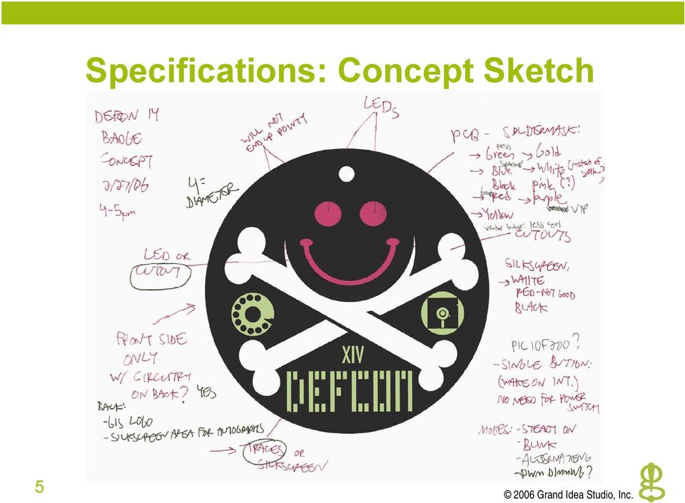
6 Specifications: Defined Feature Set After some back-and-forth discussions, we settled on the functionality and artistic elements: DEFCON logo and icons on top copper layer Crossbones and smile to be cutout Different soldermask colors for different DEFCON clientele Single button for user control (no power switch) Multiple LED states: o o o Both Steady On Both Blink Alternating Random (Pseudo-random, actually) o 6
 Multiple LED states: o o o Both Steady On Both Blink Alternating Random (Pseudo-random,")
7 Preliminary Schematic 7
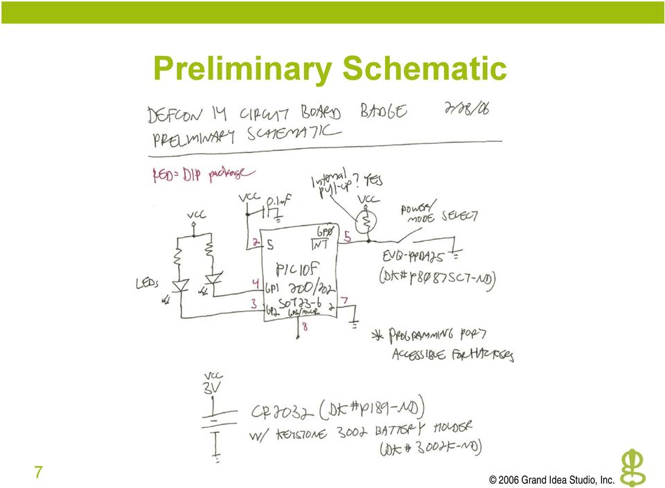
8 Breadboarding/Code Development 1. Turn preliminary sketch into something physical 2. Evaluate different types of LEDs 3. Write the embedded code for the Microchip PIC10F202 processor 4. Fine-tune and tweak hardware and code until it functions as specified 8

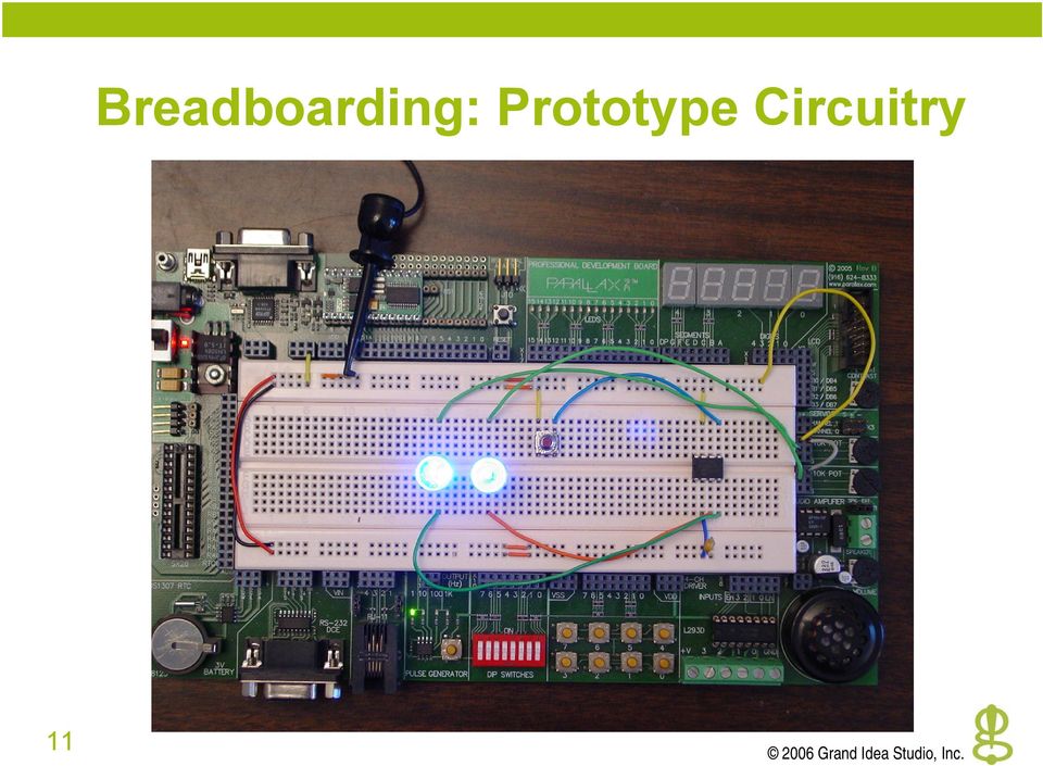
9 Breadboarding Breadboarding: A method to build circuits without soldering or creating custom PCBs The ideal method of prototyping Utilizes a plug board and 24AWG solid wire Not recommended for high frequency/rf circuits 9

10 Breadboarding: LED Evaluation 10

11 Breadboarding: Prototype Circuitry 11
12 Code Development Used CCS PCM compiler for Microchip PIC10F202 with MPLAB IDE v7.30 Ex.: Free development tools are available, too ( Simple state machine typedef enum { SLEEP, STEADY, BLINK, ALT, RANDOM } state_type; 12
 Simple state machine typedef enum { SLEEP, STEADY, BLINK,")
13 Code Development 2 13

14 Final Schematic 14

15 Drawing Schematics Many professional tools available, mostly in the $5k-$10k range Ex.: Cadence/OrCAD Capture, Ex.: Altium/Protel DXP, Demo licenses for some professional tools Usually expire after 30 days Some fully-free software available Ex.: geda, complete opensource PCB, schematic capture, and simulation for Unix platforms 15

16 Drawing Schematics 2 Microsoft Visio can perform rudimentary schematic capture using common symbols Cannot easily create custom parts Cannot export a Netlist for use with PCB design 16

17 Bill-of-Materials Cost issues (had to keep around $5/unit total) Had to make sure that all selected components were available in large quantities Used trusty Digi-Key and Mouser catalogs to create first draft BOM Enlisted Future Electronics to help with cost reduction and large quantity ordering Typically 30% of the cost of Digi-Key, Mouser, etc. More on this later 17

18 Bill-of-Materials 2 18

19 PCB Design Three general methods to create custom PCBs: 1. Homebrew w/ PCB etching kit 2. PCB prototyping systems 3. Professional fabrication Printed Circuit Board (PCB) etching kit Low-cost method for quick homebrew hacks (practically instant gratification) Uses hazardous chemicals (ferric chloride) which etch away any copper on the circuit board that isn't protected by resistant ink or toner Ex.: MAKE Magazine issue 2 19
 Uses hazardous chemicals (ferric chloride) which etch away any copper")
20 PCB Design 2 November 1993 April

21 PCB Design 3 PCB prototyping systems Highly specialized, accurate CNC machine Allows quick in-house creation of prototype PCBs > $10k for a decent system Not practical for most hardware hacking purposes Ex.: LPKF Laser & Electronics ( and T-Tech ( 21
22 PCB Design 4 Professional fabrication More convenient and better quality than homebrew, why bother with dangerous chemicals anymore? Can handle very fine pitch, tight tolerances, etc. Prototype and production quantities Competition between firms leads to good deals for us o o o Prototype specials On-time guarantees Price matching 2-layer board costs ~$20-30 each (~$1-$5 in quantity) 4-layer board costs ~$50 each (~$3-$10 in quantity) 22
23 PCB Design 5 Many production houses available online e-teknet, Advanced Circuits, Sierra Proto Express, AP Circuits, Express PCB, e-teknet fabricated and assembled the prototype and production DEFCON badges Check them out in the exhibitor area (No, I didn t get paid to put this in here!) 23
24 Design tools PCB Design 6 Many professional tools available, some upwards of $5k-$10k o o Ex.: Altium/Protel DXP, Ex.: McCAD EDS, pin limit for free Some fully-free software available o o o Ex.: geda, complete open-source PCB, schematic capture, and simulation for Unix platforms Ex.: Protel EasyTrax, easytrax.zip, DOS freeware version, complete PCB layout package with output support for printers and Gerber Ex.: Express PCB offers a free captive design tool for use with their own manufacturing 24
25 High-level process: PCB Design 7 1. Create schematic 2. Output Netlist 3. Import Netlist into PCB design software 4. Create PCB 5. Output Gerber plots 6. Submit Gerber plots to PCB fab house 25
26 Badge PCB Design: Process 1. Verify desired size of badge & artistic elements 2. Create mechanical outline of board 3. Add logos to top side copper 4. Place components in desired locations 5. Import Netlist (based on final schematic) 6. Route board (keep all traces on bottom side) 7. Add logos to bottom side silkscreen 8. Run verification tests 9. Output Gerber plots 26
27 Badge PCB Design: Verifying Sizes 27
28 Badge PCB Design: Mechanical Layer 28
29 Badge PCB Design: Top Layer 29
30 Badge PCB Design: Bottom Layer 30
31 Badge PCB Design: Mock-up 31
32 Prototype Testing Before placing large order of PCBs, need to verify that the design functions as expected Ordered a few bare prototype PCBs from e-teknet Had careful discussions with them to ensure that our complicated cutout areas and features were conveyed properly to their Chinese factory I m sure they re sick of me by now! Hand-assembled some boards Sent to The Dark Tangent and Ping for final sign-off 32
33 Prototype Testing: Current Measurements 33
34 Prototype Testing: Current Measurements 2 34
35 Joe says A-OK! 35
36 Parts Sourcing Ended up being the most difficult/time consuming part of the process On strict deadline to obtain parts for 6,055 units and ship to e-teknet to begin assembly No parts == No badges for DEFCON! Placed all quantity orders with Future Electronics Since Future (and most large distributors) has minimums and multiple requirements, ordered remaining pieces from Digi-Key & Mouser Used Digi-Key to purchase and program code into PIC10F202s 36
37 Issues w/ Future: Misquoted leadtimes Parts Sourcing 2 o They ll be here in 3 weeks parts arrive after 6 Lost parts o Only 500 LEDs were shipped sales couldn t find the other 11,700!? Slow shipping o What part of I need these parts tomorrow do you not understand? After much pressure, I was upgraded to a more competent sales contact All problems were finally resolved! 37
38 Parts Sourcing 3 38
39 Quantity Order Placed 6,055 unit order with e-teknet While components were being acquired, they helped us decide on the seven soldermask colors and began PCB fabrication Sent them BOM, Parts Placement, and Test Procedure to aid in assembly Tested and approved First Articles Pulled the trigger on the full quantity build! 39
40 Quantity Order: Color Samples 40
41 Quantity Order: Final Colors 41
42 Parts Placement 42
43 Parts Placement 2 43
44 Test Procedure 44
45 Test Procedure 2 45
46 Test Procedure 3 46
47 Test Procedure 4 47
48 Test Procedure 5 48
49 First Article Approval: Front 49
50 First Article Approval: Back 50
51 DEFCON Badge Hacking Contest What can you do with two LEDs, a switch, some discretes, and a Microchip PIC10F202? The most obscure, obscene, or mischievous badge hack will be recognized and awarded at the DEFCON Award Ceremonies on Sunday Microchip development tools are available at the show for your use Find me later if you want to check out what I ve done to mine 51
52 Thanks for Coming! Joe Grand (Kingpin)
Prototyping Printed Circuit Boards
 Prototyping Printed Circuit Boards From concept to prototype to production. (HBRC) PCB Design and Fabrication Agenda Introduction Why PCBs? Stage 1 Understanding the rules Stage 2 Planning the board. Stage
EECAD s MUST List MUST MUST MUST MUST MUST MUST MUST MUST MUST MUST
 Customers are required to follow certain criteria for all designs whether they are ultimately done in EECAD or by the customers themselves. These criteria, approved by EES Management, are listed below:
Executive Summary. Table of Contents
 Executive Summary How to Create a Printed Circuit Board (PCB) Department of Electrical & Computer Engineering Michigan State University Prepared by: John Kelley Revision: 4/06/00 This application note
! Making your own Open Source Hardware Arduino Shield with Fritzing. Justin Mclean justin@classsoftware.com
 ! Making your own Open Source Hardware Arduino Shield with Fritzing Justin Mclean justin@classsoftware.com Make Your Own Arduino Shield Want to make your own shield Have limited electronics experience
This presentation is courtesy of PCB3D.COM
 Printed Circuit Board Design, Development and Fabrication Process This presentation is courtesy of PCB3D.COM Steve Rose Printed Circuit Board Design Engineer Slide 1 Introduction PCB 101 This presentation
PCB Design. Gabe A. Cohn. May 2010. Using Altium Designer/DXP/Protel. Electrical Engineering University of Washington
 PCB Design Using Altium Designer/DXP/Protel Gabe A. Cohn May 2010 Electrical Engineering University of Washington Printed Circuit Board Steps 1. Draw schematics 2. Attach footprints for all components
An Introduction to MPLAB Integrated Development Environment
 An Introduction to MPLAB Integrated Development Environment 2004 Microchip Technology Incorporated An introduction to MPLAB Integrated Development Environment Slide 1 This seminar is an introduction to
Fabrication of Printed Circuit Boards Using a Table Top CNC Mill
 Fabrication of Printed Circuit Boards Using a Table Top CNC Mill by Christopher F. Departmental Engineer, New Mexico State University, Department of Engineering Technology and Surveying Engineering PO
Designing a Printed Circuit Board
 Designing a Printed Circuit Board Jamie Jacobs Design Team 4 4/03/2009 Abstract When the development stage of a circuit board is complete and working correctly, it is then necessary to take this breadboard
Complete. PCB Design Using. NI Multisim, NI Ultiboard, LPKF CircuitCAM and BoardMaster. pg. 1. Wei Siang Pee
 Complete Wei Siang Pee PCB Design Using NI Multisim, NI Ultiboard, LPKF CircuitCAM and BoardMaster pg. 1 Introduction Multisim equips educators, students, and professionals with the tools to analyze circuit
ENGS 32 Winter, 2003. Prototyping Methods
 There s more on this in Scherz, Practical Electronics for Inventors. Solderless Breadboard or Plugboard This is what we ve been using in lab. Very fast to build and make changes. Works well with DIP ICs
Reverse Engineering: Printed Circuit Boards. Dr. Tarek A. Tutunji Philadelphia University, Jordan
 Reverse Engineering: Printed Circuit Boards Dr. Tarek A. Tutunji Philadelphia University, Jordan Reference PCB Reverse Engineering by John Armistead A Rapid Prototyping Methodology for Reverse Engineering
Designing a Schematic and Layout in PCB Artist
 Designing a Schematic and Layout in PCB Artist Application Note Max Cooper March 28 th, 2014 ECE 480 Abstract PCB Artist is a free software package that allows users to design and layout a printed circuit
Surveillance System Using Wireless Sensor Networks
 Surveillance System Using Wireless Sensor Networks Dan Nguyen, Leo Chang Computer Engineering, Santa Clara University Santa Clara, California, USA dantnguyen84@gmail.com chihshun@gmail.com Abstract The
Development of a Software for the Design of Electronic Circuits in 3D-Printable Objects Colloquium - Bachelor Thesis
 Development of a Software for the Design of Electronic Circuits in 3D-Printable Objects 2ahlers@informatik.uni-hamburg.de University of Hamburg MIN Faculty Department Informatics January 19, 2016 Problem
How to avoid Layout and Assembly got chas with advanced packages
 How to avoid Layout and Assembly got chas with advanced packages Parts and pitch get smaller. Pin counts get larger. Design cycles get shorter. BGA, MicroBGA, QFN, DQFN, CSP packages are taking the design
Best Practices in PCB Design: Exporting Gerber Files
 Page 1 of 5 Improve your ni.com experience. Login or Create Document Type: Tutorial NI Supported: Yes Publish Date: Mar 4, 2009 Best Practices in PCB Design: Exporting Gerber Files Overview This document
How to Build a Printed Circuit Board. Advanced Circuits Inc 2004
 How to Build a Printed Circuit Board 1 This presentation is a work in progress. As methods and processes change it will be updated accordingly. It is intended only as an introduction to the production
PCB Artist Tutorial:
 Derek Brower browerde@msu.edu Capstone Design Team 6 PCB Artist Tutorial: Printed Circuit Board Design Basics N o v e m b e r 1 4, 2 0 1 2 P C B B a s i c s P a g e 1 Abstract PCB Artist is a schematic
EXPRESS PCB TUTORIAL Author: Lee Morey Revised: JE Feb 2015
 EXPRESS PCB TUTORIAL Author: Lee Morey Revised: JE Feb 2015 Getting Started There are several resources for learning how to layout schematics and PCBs. And there are several popular commercial packages.
Laboratory 2. Exercise 2. Exercise 2. PCB Design
 Exercise 2. PCB Design Aim of the measurement Introducing to the PCB design Creating a schematic of an analog circuit, making simulations on it and designing a Printed circuit board for it. Keywords Printed
PCB Board Design. PCB boards. What is a PCB board
 PCB Board Design Babak Kia Adjunct Professor Boston University College of Engineering Email: bkia -at- bu.edu ENG SC757 - Advanced Microprocessor Design PCB boards What is a PCB board Printed Circuit Boards
Component, Model and Library Concepts
 Component, Model and Library Concepts Summary Article AR0104 (v2.0) June 07, 2006 This article defines components, models and libraries, and their relationships. The search sequence for locating models
Design Project: Power inverter
 Design Project: Power inverter This worksheet and all related files are licensed under the Creative Commons Attribution License, version 1.0. To view a copy of this license, visit http://creativecommons.org/licenses/by/1.0/,
Introduction to Photolithography Concepts via printed circuit board (PCB) manufacturing. PCB Background Information (courtesy of Wikipedia)
 manufacturing. PCB Background Information (courtesy of Wikipedia)") Introduction to Photolithography Concepts via printed circuit board (PCB) manufacturing Introduction As you saw on the video (http://www.youtube.com/watch?v=9x3lh1zfggm), photolithography is a way to nanomanufacture
Introduction to Photolithography Concepts via printed circuit board (PCB) manufacturing Introduction As you saw on the video (http://www.youtube.com/watch?v=9x3lh1zfggm), photolithography is a way to nanomanufacture
Breathe. Relax. Here Are the Most Commonly Asked Questions and Concerns About Setting Up and Programming the SurroundBar 3000.
 Breathe. Relax. Here Are the Most Commonly Asked Questions and Concerns About Setting Up and Programming the SurroundBar 3000. Our Customer Service Department has compiled the most commonly asked questions
Electronic Circuit Prototyping Techniques
 Electronic Circuit Prototyping Techniques Document Revision: 1.01 Date: February, 2007 16301 Blue Ridge Road, Missouri City, Texas 77489 Telephone: 1-713-283-9970 Fax: 1-281-416-2806 E-mail: info@bipom.com
LEAN NPI AT OPTIMUM DESIGN ASSOCIATES: PART 1 WHERE ARE WE NOW? RANDY HOLT, OPTIMUM DESIGN ASSOCIATES JAMES DOWDING, MENTOR GRAPHICS
 W H I T E P A P E R LEAN NPI AT OPTIMUM DESIGN ASSOCIATES: PART 1 WHERE ARE WE NOW? RANDY HOLT, OPTIMUM DESIGN ASSOCIATES JAMES DOWDING, MENTOR GRAPHICS w w w. o d b - s a. c o m For more than twenty years,
Module 1: Getting Started With Altium Designer
 Module 1: Getting Started With Altium Designer Module 1: Getting Started With Altium Designer 1.1 Introduction to Altium Designer... 1-1 1.1.1 The Altium Designer Integration Platform...1-1 1.2 The Altium
Quadra Solutions. Your Partner for PCB Design Success
 Quadra Solutions Your Partner for PCB Design Success PCB DESIGN SERVICES Consider us an extension to your PCB design team Quadra houses one of the largest PCB design bureaus in the UK, but we don t just
PCB Project (*.PrjPcb)
") Project Essentials Summary The basis of every design captured in Altium Designer is the project. This application note outlines the different kinds of projects, techniques for working on projects and how
Project Essentials Summary The basis of every design captured in Altium Designer is the project. This application note outlines the different kinds of projects, techniques for working on projects and how
FREE. www.designspark.com/pcb. Professional standard PCB design tool DesignSpark PCB. resources by
 FREE DESIGNSPARK Professional standard PCB design tool DesignSpark PCB version 4 Unique resources by DesignSpark PCB is an award-winning professional software package for schematic capture and PCB layout,
Acceptability of Printed Circuit Board Assemblies
 Section No.: 12I.2.3, Sheet 1 of 9 Rev Level: 16 Additional Distribution: PCB Assembly Subcontractors 1.0 Purpose 2.0 Scope Acceptability of Printed Circuit Board Assemblies 1.1 The purpose of this standard
Programmable Frequency Synthesizer
 Sample Proposal Programmable Frequency Synthesizer Note from BF: This was submitted by a student in EE413 in a previous semester. The proposal has some shortcomings, but it will give you a good idea of
Improve PCB Layout with Skill Utility Programs
 Improve PC Layout with Skill Utility Programs rbel Nissan, COO, Nistec Design Published at PCD&F Magazine, May 2008 Faster time to market is crucial in the development and manufacturing of every new product.
Count on Optima Technology Associates to meet your requirements
 Since 1995, Global Resources, Local Support When you need quality Printed Circuit Boards To Spec On Time On Budget Count on Optima Technology Associates to meet your requirements Optima Technology Associates,
HOW PRODUCTS GET DESIGNED
 HOW PRODUCTS GET DESIGNED Introduction: This is a description of DFAD s role as an electronics design center, in designing products or projects for you. It also explains the interactions between all parties
Guide to Designing and Fabricating Printed Circuit Boards
 Guide to Designing and Fabricating Printed Circuit Boards Rev 1.0 University of Toronto January 2006 Contact for ECE496 students: Olivier Trescases trescas@vrg.utoronto.ca Outline Outline...2 Glossary...3
LO5: Understand commercial circuit manufacture
 Unit 6: Circuit simulation and manufacture LO5: Understand commercial circuit manufacture Commercial component and PCB types Instructions and answers for teachers These instructions should accompany the
Multilevel Socket Technologies
 Multilevel Socket Technologies High Performance IC Sockets And Test Adapters Overview Company Overview Over 5,000 products High Performance Adapters and Sockets Many Custom Designs & Turn-Key Solutions
KUMU A O CUBESAT: ELECTRICAL POWER SUBSYSTEM. Jordan S. Torres Department of Electrical Engineering University of Hawai i at Mānoa Honolulu, HI 96822
 KUMU A O CUBESAT: ELECTRICAL POWER SUBSYSTEM Jordan S. Torres Department of Electrical Engineering University of Hawai i at Mānoa Honolulu, HI 96822 ABSTRACT The objective of the electrical power subsystem
Rogers 3003, 3006, 3010, 3035, 3203, 3206, 3210
 Stocked Materials: RIGID STANDARD FR4 High Tg 170c Black FR4 Polyclad 370HR (Lead Free) HIGH RELIABILITY Polyimide (Arlon 85N, Isola P96) BT (G200) HIGH FREQUENCY: Park Nelco 4000-13, 4000-13si Getek Gore
PICAXE VSM Tutorial Part 4
 PICAXE VSM Tutorial Part 4 In the fourth part of our PICAXE VSM tutorial we look at how to export a Bill of Materials (BoM). We also look at how to generate a PCB netlist for use in various PCB applications.
step 1 Unpack the lunchbox And check whether you have got all the components~ If you have questions please contact us at: info@unitunlikely.
 step 1 Unpack the lunchbox And check whether you have got all the components~ If you have questions please contact us at: info@unitunlikely.com This part is called the PCB (printed circuit board). All
How To Make A Pb Design Guide For A Pcr (Dcfm) And Pb (Dfm) On A Pcb (Plb) On An Iphone Or Ipb (Pb) For A Powerbook
 And Pb (Dfm) On A Pcb (Plb) On An Iphone Or Ipb (Pb) For A Powerbook") Your PCB layout First time right Smart menus & PCB visualizer DRC/DFM free online tools s Hertogenbosch 29 October 2014 Slide 1 PCB visualisation - Goals Help busy designers get boards on time accurate
Your PCB layout First time right Smart menus & PCB visualizer DRC/DFM free online tools s Hertogenbosch 29 October 2014 Slide 1 PCB visualisation - Goals Help busy designers get boards on time accurate
CAD and Drawing Style Procedure
 CAD and Drawing Style Procedure 0.1.1.8 Rev. 4 Date: 2014-Nov-20 Copyright 2014, Canadian Light Source Inc. This document is the property of Canadian Light Source Inc. (CLSI). No exploitation or transfer
This lab is due 5:30PM Tuesday November 2, 2010 at 115 Hackerman Hall
 M.E. 530.420 Lab 7: Printed Circuit Board Design Louis L. Whitcomb Department of Mechanical Engineering G.W.C. Whiting School of Engineering The Johns Hopkins University This lab is due 5:30PM Tuesday
Using CAD Data in Assembly - Advantages and Pitfalls
 Using CAD Data in Assembly - Advantages and Pitfalls For years, electronic engineers and circuit board designers have shared information between their computer-aided-engineering (CAE) and computer-aided-design
Application Note: PCB Design By: Wei-Lung Ho
 Application Note: PCB Design By: Wei-Lung Ho Introduction: A printed circuit board (PCB) electrically connects circuit components by routing conductive traces to conductive pads designed for specific components
OPL BASIC. Dosing System for Professional Laundry machines. Contents
 OPL BASIC Dosing System for Professional Laundry machines Contents 1 Getting Started. Page 2 2 Installation. Page 4 3 Set Up & Operation. Page 8 4 Maintenance & Accessories. Page 10 5 Troubleshooting Page
Tutorial for MPLAB Starter Kit for PIC18F
 Tutorial for MPLAB Starter Kit for PIC18F 2006 Microchip Technology Incorporated. All Rights Reserved. WebSeminar Title Slide 1 Welcome to the tutorial for the MPLAB Starter Kit for PIC18F. My name is
Capacitive Touch Sensor Project:
 NOTE: This project does not include a complete parts list. In particular, the IC described here does not come in a dual-inline-package (DIP), and so a gull-wing package has to be soldered to an adaptor
Be the best. PCBA Design Guidelines and DFM Requirements. Glenn Miner Engineering Manager March 6, 2014 DFM DFT. DFx DFC DFQ
 and DFM Requirements DFM DFQ DFx DFT DFC Glenn Miner Engineering Manager Electronics, Inc. Not to be reproduced or used in any means without written permission by Benchmark. Guidelines and Requirements
PCB Fabrication Services and Preparation
 PCB Fabrication Services and Preparation RSGC ACES PCB Fabrication Service Providers Bittele Electronics Inc. Preparing Eagle Files For Production What is a Gerber RS-274X File? Short Wikipedia Spiel Creating
How to make a Quick Turn PCB that modern RF parts will actually fit on!
 How to make a Quick Turn PCB that modern RF parts will actually fit on! By: Steve Hageman www.analoghome.com I like to use those low cost, no frills or Bare Bones [1] type of PCB for prototyping as they
Review of. 4x IOcards (PCBs) Manufactured by Opencockpits
 Manufactured by Opencockpits") Review of 4x IOcards (PCBs) Manufactured by Opencockpits Intro We all know flight simulation hardware as yokes, pedals, throttle quadrant, various complete P&P modules etc. which certainly helps in creating
Review of 4x IOcards (PCBs) Manufactured by Opencockpits Intro We all know flight simulation hardware as yokes, pedals, throttle quadrant, various complete P&P modules etc. which certainly helps in creating
Your End-to-End PCB products design and Manufacturing in the 21 st Century
 Your End-to-End PCB products design and Manufacturing in the 21 st Century Who Are We? An engineering and manufacturing company dedicated to the advancement of technology that provides solutions related
The Value of PCB Manufacturing Quality During Prototype: You Get More Than You Pay For
 The Value of PCB Manufacturing Quality During Prototype: You Get More Than You Pay For Introduction In a recent research document, Michelle Boucher, from The Aberdeen Group, writes: "The number of engineering
Programming PIC Microcontrollers in PicBasic Pro Lesson 1 Cornerstone Electronics Technology and Robotics II
 Programming PIC Microcontrollers in PicBasic Pro Lesson 1 Cornerstone Electronics Technology and Robotics II Administration: o Prayer PicBasic Pro Programs Used in This Lesson: o General PicBasic Pro Program
Printed Circuit Assemblies
 Developing Printed Circuit Assemblies From Specifications to Mass Production Elaine Rhodes and Paul A. Spalitta Generating Specifications Developing Prototypes Going to Production Developing Printed Circuit
Overcoming the Top Five Challenges in Electro-Mechanical Product Development
 White Paper Challenges in Electro-Mechanical Product Development Page 1 of 5 Overcoming the Top Five Challenges in Electro-Mechanical Product Development The pressures of globalization and consolidation
1. Single sided PCB: conductors on only one surface of a dielectric base.
 The Department of Electrical Engineering at IIT Kanpur has a variety of devices and machines to produce single layer, double layer plated through printed circuit boards (PCBs), multi layer (max 8 layers)
IIB. Complete PCB Design Using OrCAD Capture and PCB Editor. Kraig Mitzner. ~»* ' AMSTERDAM BOSTON HEIDELBERG LONDON ^ i H
 Complete PCB Design Using OrCAD Capture and PCB Editor Kraig Mitzner IIB ~»* ' AMSTERDAM BOSTON HEIDELBERG LONDON ^ i H NEW YORK * OXFORD PARIS SAN DIEGO ШШЯтИ' ELSEVIER SAN FRANCISCO SINGAPORE SYDNEY
Assembly and User Guide
 1 Amp Adjustable Electronic Load 30V Max, 1 Amp, 20 Watts Powered by: 9V Battery Assembly and User Guide Pico Load is a convenient constant current load for testing batteries and power supplies. The digital
Flexible Printed Circuits Design Guide
 www.tech-etch.com/flex Flexible Printed Circuits Design Guide Multilayer SMT Assembly Selective Plating of Gold & Tin-Lead Fine Line Microvias Cantilevered & Windowed Leads 1 MATERIALS CONDUCTOR Copper
A TOTAL SOLUTION FOR ALL YOUR CONTRACT ELECTRONICS MANUFACTURE
 www.hcduk.com A TOTAL SOLUTION FOR ALL YOUR CONTRACT ELECTRONICS MANUFACTURING DESIGN MANUFACTURE ASSEMBLY SERVICES THAT FIT TOGETHER PERFECTLY WHO ARE HCD We are a Sub Contract Electronics Manufacturer
Tutorials Drawing a 555 timer circuit
 Step 1 of 10: Introduction This tutorial shows you how to make an electronic circuit using Livewire and PCB Wizard 3. You should follow this tutorial to learn the basic skills you will need to use Livewire
Mitigating the High Cost of PCB Documentation
 Mitigating the High Cost of PCB Documentation by Mark Gallant DownStream Technologies The goal of minimizing the time and cost for engineering a new product and getting it to market before the competition
PCB Prototyping Machine. Auto Lab. Tutorial MITS Electronics
 PCB Prototyping Machine Auto Lab Tutorial MITS Electronics REVISION: October 1, 2011 1st edition CONTENTS: Design Pro Applications Import Gerber Files Import Drill File Auto Drill Generate Outline Generate
Fax. Frequently Asked Questions (FAQ)
") Fax Frequently Asked Questions (FAQ) Updated: January 7, 2016 Frequently Asked Questions (FAQ)...1 Fax Problems Troubleshooting Checklist...2 Introduction... 2 I used to get my fax report without difficulty.
Fax Frequently Asked Questions (FAQ) Updated: January 7, 2016 Frequently Asked Questions (FAQ)...1 Fax Problems Troubleshooting Checklist...2 Introduction... 2 I used to get my fax report without difficulty.
Here s your guide to easy installation. Get the most out of Verizon High Speed Internet.
 Here s your guide to easy installation. Get the most out of Verizon High Speed Internet. Congratulations on choosing Verizon High Speed Internet. In this guide, you ll find everything you need to set up
Creating a Project with PSoC Designer
 Creating a Project with PSoC Designer PSoC Designer is two tools in one. It combines a full featured integrated development environment (IDE) with a powerful visual programming interface. The two tools
Bluetooth + USB 16 Servo Controller [RKI-1005 & RKI-1205]
![Bluetooth + USB 16 Servo Controller [RKI-1005 & RKI-1205]](/thumbs/40/21161302.jpg "Bluetooth + USB 16 Servo Controller [RKI-1005 & RKI-1205]") Bluetooth + USB 16 Servo Controller [RKI-1005 & RKI-1205] Users Manual Robokits India info@robokits.co.in http://www.robokitsworld.com Page 1 Bluetooth + USB 16 Servo Controller is used to control up to
Bluetooth + USB 16 Servo Controller [RKI-1005 & RKI-1205] Users Manual Robokits India info@robokits.co.in http://www.robokitsworld.com Page 1 Bluetooth + USB 16 Servo Controller is used to control up to
Controlling a Dot Matrix LED Display with a Microcontroller
 Controlling a Dot Matrix LED Display with a Microcontroller By Matt Stabile and programming will be explained in general terms as well to allow for adaptation to any comparable microcontroller or LED matrix.
Company Introduction. Welcome to BEST. bestpcbs.com. http://www.bestpcbs
 Company Introduction Welcome to BEST http://www.bestpcbs bestpcbs.com Company Introduction YOUR BEST SOURCE IN ASIA We are dedicated to providing quality, service and value to our customers While maintaining
This first tutorial goes over how to install the software, and tailor-fit its interface and support files.
 1 of 8 Printed circuit boards (PCBs) are the backbone of every electronic gizmo out there. They re not flashy like those microprocessors, or abundant like resistors, but they re essential to making all
Portable Cell Phone Charger: Design and Manufacturing
 Portable Cell Phone Charger: Design and Manufacturing Miguel Contreras Junior Electrical Engineering California Polytechnic State University 1926 Canyon Circle San Luis Obispo, CA 93410-1710 (408) 655-5010
VECTORAL IMAGING THE NEW DIRECTION IN AUTOMATED OPTICAL INSPECTION
 VECTORAL IMAGING THE NEW DIRECTION IN AUTOMATED OPTICAL INSPECTION Mark J. Norris Vision Inspection Technology, LLC Haverhill, MA mnorris@vitechnology.com ABSTRACT Traditional methods of identifying and
Get PCB Prototypes Sooner with In-House Rapid PCB Prototyping
 Get PCB Prototypes Sooner with In-House Rapid PCB Prototyping Save Time with In-House Prototyping In-house circuit board prototyping eliminates waiting for external suppliers. With LPKF systems and solutions,
QUASAR ELECTRONICS KIT No. 1015 ELECTRONIC MOSQUITO REPELLER
 QUASAR ELECTRONICS KIT No. 1015 ELECTRONIC MOSQUITO REPELLER General Description This simple circuit can prove itself worth many times its value (which is very reasonable anyway) in getting rid of mosquitoes
OrCad Layout Plus PCB Tutorial
 OrCad Layout Plus PCB Tutorial R. B. Reese (9/2005), ECE, MSU. RBR/V 0.5 1 OrCad Layout Plus PCB Tutorial This is a simple tutorial of OrCAD PCB using a two-layer PCB with throughhole components. The design
Dec06-04: Geek Binary Alarm Clock
 Software Requirements Specification for Dec06-04: Geek Binary Alarm Clock Version 1.1 Prepared by Yesuratnam Thommandru Iowa State University Electrical and Computer Engineering September 28, 2006 Software
Miniaturizing Flexible Circuits for use in Medical Electronics. Nate Kreutter 3M
 Miniaturizing Flexible Circuits for use in Medical Electronics Nate Kreutter 3M Drivers for Medical Miniaturization Market Drivers for Increased use of Medical Electronics Aging Population Early Detection
Pololu DRV8835 Dual Motor Driver Shield for Arduino
 Pololu DRV8835 Dual Motor Driver Shield for Arduino Pololu DRV8835 Dual Motor Driver Shield for Arduino, bottom view with dimensions. Overview This motor driver shield and its corresponding Arduino library
AN588 ENERGY HARVESTING REFERENCE DESIGN USER S GUIDE. 1. Kit Contents. 2. Introduction. Figure 1. Energy Harvesting Sensor Node
 ENERGY HARVESTING REFERENCE DESIGN USER S GUIDE 1. Kit Contents The RF to USB Reference Design contains the following items: Si1012 Energy Harvesting Wireless Sensor Node EZRadioPRO USB Dongle ToolStick
Using Stencils to Simplify the Printed Circuit Board Assembly Process
 Using Stencils to Simplify the Printed Circuit Board Assembly Process Author: Nolan Johnson CAD/EDA Manager njohnson@sunstone.com The process of creating a prototype circuit board requires multiple phases
POWER FORUM, BOLOGNA 20-09-2012
 POWER FORUM, BOLOGNA 20-09-2012 Convertitori DC/DC ad alta densità di potenza e bassa impedenza termica. Massimo GAVIOLI. Senior Field Application Engineer. Intersil SIMPLY SMARTER Challenges when Designing
Universal ICSP-Programming-Adapter for all PIC s in DIL-Housings
 Universal ICSPProgrammingAdapter for all PIC s in DILHousings Author: sprut Date: 08.0.2 Table of Contents TERMS OF USE:...3 2 Introduction...3 3 WireConnections...4 3. PICMicrocontroller...4 3.. PICFx
CHAPTER 5. OVERVIEW OF THE MANUFACTURING PROCESS
 CHAPTER 5. OVERVIEW OF THE MANUFACTURING PROCESS 5.1 INTRODUCTION The manufacturing plant considered for analysis, manufactures Printed Circuit Boards (PCB), also called Printed Wiring Boards (PWB), using
Rigid-Flex Technology: Mainstream Use but More Complex Designs by John Isaac October 1, 2007
 Rigid-Flex Technology: Mainstream Use but More Complex Designs by John Isaac October 1, 2007 In the past, flex and rigid-flex technology was typically used in applications that could tolerate long design
BUILD YOUR OWN RC SWITCH (Issue 3)
") PART ONE SINGLE ELECTRONIC RC SWITCH Fancy switching the lights using your radio, then here is a circuit you may consider building. It only uses one IC and seven other components for a single switch and
PART ONE SINGLE ELECTRONIC RC SWITCH Fancy switching the lights using your radio, then here is a circuit you may consider building. It only uses one IC and seven other components for a single switch and
CadSoft EAGLE Version 7
 CadSoft EAGLE Version 7 System Requirements EAGLE is a powerful graphics editor for designing PC-board layouts and schematics. In order to run EAGLE the following is required: Windows 7, or newer Linux
ERNI Systems USA Backplanes & Sub-Racks: Design, Simulation, Manufacturing and Test
 ERNI Systems USA Backplanes Sub-Racks: Design, Simulation, Manufacturing and Test www.erni.com Engineering From Beginning to End Conceptualization From Customer Idea to Statement of Work (SOW) Structuring
HP UPS R1500 Generation 3
 HP UPS R1500 Generation 3 Installation Instructions Part Number 650952-001 NOTE: The rating label on the device provides the class (A or B) of the equipment. Class B devices have a Federal Communications
ELECTRICAL WORK ORDER
 ELECTRICAL WORK ORDER Deadline In order to receive advance rates, orders must be received with payment in full, a minimum of 20 days prior to the first move in date. Orders received after that date or
RC2200DK Demonstration Kit User Manual
 Demonstration Kit User Manual Table of contents TABLE OF CONTENTS... 1 QUICK INTRODUCTION... 2 INTRODUCTION... 3 DEMONSTRATION BOARD... 4 POWER SUPPLY SECTION... 5 RS-232 INTERFACE... 6 CONNECTORS... 7
Fondamenti su strumenti di sviluppo per microcontrollori PIC
 Fondamenti su strumenti di sviluppo per microcontrollori PIC MPSIM ICE 2000 ICD 2 REAL ICE PICSTART Ad uso interno del corso Elettronica e Telecomunicazioni 1 2 MPLAB SIM /1 MPLAB SIM is a discrete-event
One-List Board Design Methodology. Overview. Core competency. SANBlaze: Inside contents Overview 1. Technology, Inc.
 SAN Technology, Inc. One-List Board Design Methodology SANBlaze Technology Inc, (978) 679-1400 SANBlaze: Proven methodology for successful custom product designs Overview Inside contents Overview 1 Core
COPPER FLEX PRODUCTS
 COPPER FLEX PRODUCTS WHY FLEX? Molex ible Printed Circuit Technology is the answer to your most challenging interconnect applications. We are your total solution for ible Printed Circuitry because we design
Digital I/O: OUTPUT: Basic, Count, Count+, Smart+
 Digital I/O: OUTPUT: Basic, Count, Count+, Smart+ The digital I/O option port in the 4-Series provides us with 4 optically isolated inputs and 4 optically isolated outputs. All power is supplied externally.