SD2. Speech Dialler. Installation and Operator s Manual
|
|
|
- Ashley Hart
- 10 years ago
- Views:
Transcription
1 SD2 Speech Dialler Installation and Operator s Manual

2 CONTENTS OVERVIEW... 3 MAIN FEATURES... 4 SD2 LAYOUT... 7 INSTALLATION REQUIREMENTS... 8 PCB LAYOUT... 8 CONNECTIONS TO THE CONTROL PANEL... 9 CONTROL PANEL CONNECTION TABLE CONNECTIONS TO THE TELEPHONE LINE COMMISSIONING ACCESSING THE PROGRAMMING MENU PROGRAMMING MENU OPTIONS CONTACT DETAILS MESSAGES ACCESS CODES ACKNOWLEDGEMENT AND ABORT OPTIONS OUTPUT OPTIONS CALL ROUTING OPTIONS SET DATE AND TIME VIEW LOG TEST OPTIONS LEAVING PROGRAMMING USER GUIDE RECORDING AND PLAYING A MEMO LOCALLY USING THE REMOTE ACCESS FEATURE THE REMOTE ACCESS MENU RECORD/PLAY VOICE MESSAGES TEXT EDITING KEYS SPECIFICATIONS QUICK REFERENCE QUICK REFERENCE

3 Overview Introduction 3
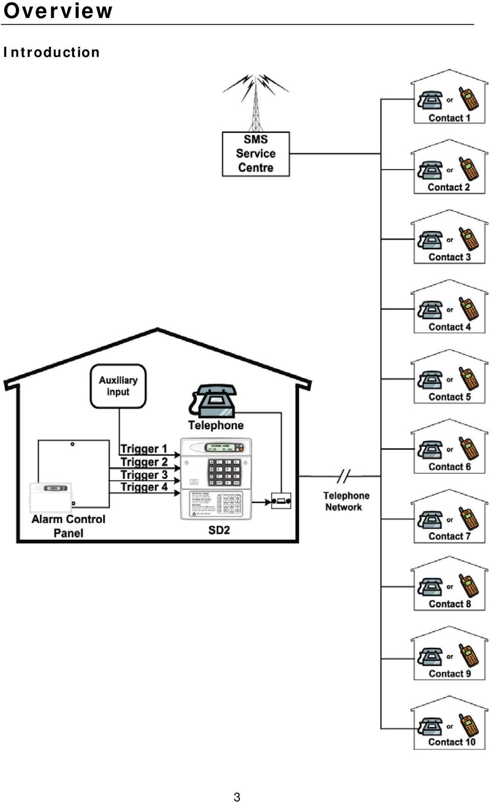
4 Main Features The SD2 provides a means of communicating alarm information from a control panel to either a standard or a mobile telephone. The unit normally connects to an alarm control panel, which provides the necessary power and battery back up. Triggers: The SD2 has four trigger inputs. You can assign a voice message and/or a text message to each input. The unit can also send a message/or a text message when the triggers have been restored. For most applications you may connect the trigger inputs to an alarm control panel's communicator outputs or bell output. You can also connect other devices, such as smoke detectors or temperature sensors, directly to the trigger inputs. The unit allows you to program the polarity of the trigger inputs as either positive or negative applied/removed. Contacts: The SD2 will store up to 10 contacts: you can assign each one a name, telephone number, message type, and acknowledgement type. DO NOT use the SD2 to call the Police via the Emergency Services phone numbers. Voice Messages: The SD2 has a built-in microphone and speaker to allow you to record and replay audio messages directly from the unit. The SD2 can store up to four separate alarm messages, four restore alarm messages (a different message can be sent when the trigger event has been removed) and one common message (normally used to store the name and address of the premises). Each message can be up to 30 seconds in length. Voice Messages A and Voice Restore Message A are related to trigger input 1; Voice Messages B and Voice Restore Message B are related to trigger input 2 and so on. Make sure that you record voice messages that reflect the type of alarm that is connected to the trigger input. For example, if you connect input 1 to the fire output of an alarm/fire control panel then make sure that Message 1 states that there is a fire alarm at the premises. 4

5 Text Messages: The SD2 can also send text messages to mobile telephones using the SMS text service (Short Message Service). The unit does this by calling a SMS service centre, which takes the text message from the SD2 and forwards it to the contact's mobile telephone. The unit can store up to four separate 32-character alarm messages, four 32-character restore alarm messages (a different message can be sent when the trigger event has been removed) and one common message (normally used to store the name and address of the premises). When the unit sends a text message, it adds the alarm message to the site details message. The site details message would normally hold the name or details of the premises being protected. Acknowledgement: On receiving a voice message call from the SD2 the contact person answering the call can acknowledge it at any time by pressing 8 on their telephone. If contact does not acknowledge the voice message then the SD2 repeats the message four times, after which the unit abandons the call and dials the next available contact. Call-Abort: The SD2 has several call-abort options, which include restoring the trigger input or entering the operator s passcode. When the unit has aborted a call it immediately shuts down and returns to its normal standby mode. Outputs: The SD2 has programmable outputs that you can use to indicate the status of the unit. You may also program the outputs for remote control. For example, you could use this facility to remotely turn outputs on and off with a touch-tone telephone. Temperature sensor: The unit can display current ambient temperature. You can program temperature high and low alarms, linking them to two corresponding output types. Time and date: The unit contains an internal clock which can display the current time and date. In addition, the time and date will be added to text messages and trigger events thus providing a useful audit trial in the log. Please note that the time and date feature is designed as a guide. 5
. When the unit sends a text message, it adds the alarm message to the site details message.")
6 Listen-In Mode: The SD2 has a listen-in mode, which switches an internal microphone to the telephone line so that you can hear activity at the protected site. The contact can activate the listen-in mode at the time of receiving a voice message or by calling into the SD2 and using the Remote Access feature. Talkback Mode: The SD2 has a talkback mode, which switches the internal loudspeaker to the telephone line so that you can talk to the protected site. The contact can activate the talkback mode at the time of receiving a voice message or by calling into the SD2 and using the Remote Access feature. Message: The SD2 has a message feature, which allows you to record up to 15 seconds of audio. A user can record a message locally, at the unit, or remotely, using a touch-tone telephone. After recording a new message the unit will indicate it on the display and optionally gives a beep. You can also program the message feature to record when a trigger input is activated. Remote Access: If you enable this feature you can access the SD2 remotely by dialling into the unit with a touch-tone telephone. Once connected you can turn on and off the two outputs, activate the listen-in/talkback mode, listen to the message, or record a new message. 6

7 SD2 Layout 1. Two-line backlit LCD display 2. Keyboard 3. Green LED follows the programming of output 1. (See page 30). 4. Red LED follows the programming of output 2. (See page 30). Function keys Scroll up Record / special character key Scroll down Clear Clear display Ent Esc Enter Escape 7

8 Installation Requirements General The SD2 is designed to connect to an intruder alarm control panel or similar. The control panel must have an auxiliary power output of between 10.5V and 14V, and the ability to provide a minimum of 100mA. The unit is supplied with a 2-metre telephone lead, which plugs directly into any standard BT socket. Cooper Security recommends that you site the unit as near to a BT telephone socket as possible. If this it not possible you should either obtain an approved BT extension lead or permanently wire the unit to the BT socket (see Connections to the Telephone Line). Mounting Instructions Separate the cover from the base by using a screwdriver to push two of the retaining clips (top or bottom) inwards from the base indents. Remove cover assembly and store in a safe place. Hold the base in position (keyhole to the top) and mark the three securing holes. Remove the base then drill and plug the holes. Pass all cables into the base through the cable entries and then secure the base to wall. PCB Layout 1. Tamper switch 2. Tamper and Trigger inputs 3. Microphone 4. Power and Programmable outputs 5. Telephone connections 6. Speaker 8
.")
9 Connection terminals on the SD2 are described as either Safety Extra Low Voltage circuits (SELV) or Telecommunications Network Voltage circuits (TNV). It is important that the TNV connections are only connected to the PSTN, and SELV circuits are only connected to designated SELV circuits. Interconnection circuits should be such that the equipment continues to comply with the requirements of 4.2 of EN for TNV circuits and 2.3 of EN for SELV circuits, after making connections between circuits. Connections to the control panel Before making any connection to the SD2 isolate ALL power from the control panel (AC mains and battery). Do not continue if there is power still present on the control panel. +12V & 0V Connect these terminals to the 12V auxiliary power supply of the alarm control panel. Trigger 1-4 Connect these terminals to the relevant outputs on the alarm control panel. When an alarm panel triggers an input, the SD2 initiates the calling sequence and plays the relevant speech and/or text message. The diagrams below show the various wiring options for the trigger inputs: Trigger inputs programmed for +ve operation Trigger inputs A B C D TRIG TAMPER OP1 OP2 12V 0V N.O Loop To 12v Auxiliary supply Trigger inputs A B C D TRIG TAMPER OP1 OP2 12V 0V N.C Loop To 12v Auxiliary supply 9

10 Trigger inputs programmed for -ve operation Trigger inputs A B C D TRIG TAMPER OP1 OP2 12V 0V N.O. Loop To 12v Auxiliary supply Trigger inputs A B C D TRIG TAMPER OP1 OP2 12V 0V N.C Loop To 12v Auxiliary supply Tamper These terminals provide tamper protection for the SD2 and should be connected to the auxiliary tamper circuit on the alarm control panel. OP1 & OP2 Two programmable switched outputs. 10

11 Control Panel Connection Table The table below shows connection details for various alarm control panels: Trigger Inputs Control Panel Trigger 12V 0V Polarity Fire PA Intruder ADE Accenta 6 N/A N/A B -ve 13V+ 13V- ADE Concept 6 N/A N/A B -ve 13V+ 13V- ADE Optima 6 N/A N/A B -ve 13V+ 13V- ADE N/A N/A B -ve 13V+ 13V- Optima XM C&K 800L N/A N/A S- -ve Aux + Aux - CQR Premier 9 FA* PA IA +ve Aux Aux 12V 0V DA Abacus 6 N/A N/A Bell -ve +12V -0V DA Abacus 8 N/A N/A Bell -ve +12V -0V Gardtec 500 N/A N/A Bell- -ve 12V 0V Series Gardtec 800 D1* PA 12Hr -ve 12V 0V Series Menvier Cct 4 Cct5 ALM -ve Aux + Aux - TS400/410 Menvier TS Comm. Comm. Comm. 3 -ve Aux + Aux - Range 1 2 Pyronix Octagon N/A PA ALM -ve Aux + Aux - Pyronix N/A N/A BA -ve Aux + Aux - Conqueror Scantronic 9448 N/A COM 2 COM 3 -ve 12V 0V Scantronic 9X5X Pin 1 Pin 2 Pin 3 -ve Pin 9 Pin 10 Series Texecom Veritas N/A N/A B -ve Aux + Aux - 8/R8/ Texecom Veritas Com1 Com2 Com3 -ve Aux + Aux - R8 Plus Texecom Veritas Com1 Com2 Com3 -ve Aux + Aux - Excel Texecom Premier Digi1* Digi2* Digi3* -ve Aux + Aux - 48/88/168 *Control panel output may require programming to the correct function. 11

12 Connections to the Telephone Line The easiest way to connect the SD2 to the telephone line is to use the telephone lead that is provided with the unit as shown below: A B A1 Standard BT telephone plug A2 However, if the lead is not long enough or a serial connection is required the SD2 can be hard wired to the telephone socket as shown below: 12

13 Commissioning Once all necessary connections have been made to the Speech Dialler, clip the cover on to the base taking care not to trap any cables. Hold down 9 and reconnect the power to the speech dialler. The SD2 displays the factory-reset menu: At this point: Pressing [ defaults the SD2 to factory settings. Pressing ] cancels the factory reset. To select the programming mode enter the default passcode of The display shows ENT to Select Phone Numbers. The unit is now ready for programming and testing. Please refer to the following pages for full details. After the SD2 has been programmed and tested, secure the front cover with screw and screw cap that is provided in the spares pack. 13
![Pressing ] cancels the factory reset. To select the programming mode enter the default passcode of 1234. The display shows ENT to Select Phone Numbers.](/docs-images/41/14893755/images/page_13.jpg "The unit is now ready for programming and testing. Please refer to the following pages for full details.")
14 Accessing the Programming Menu When the SD2 is in standby mode the display shows the following: To access the programming menu you must enter the operator s passcode (default 1234). The display shows the first menu option. You can scroll up and down through the menu options using the scroll key, or jump to a menu by pressing the relevant hot key. For example, to select the Call Log menu press 9. Simple Programming If you wish to carry out simple changes or program a basic set-up please see the Quick Reference Guide on pages 54 and

15 Programming Menu Options Once you have entered the programming menu, the following options are available: 1 Contact Details. This menu allows you to edit the dialler s contact name, telephone numbers and call types. For more information, refer to page Messages. These menus allow you to Record Voice and customise Text Messages. For more information, refer to page System Options. This menu allows you to edit the dialler s system options. For more information, refer to page Access Codes. This menu allows you to edit the dialler s user codes. For more information, refer to page Acknowledge & Abort. This menu allows you to edit the dialler s acknowledgement and abort options. For more information, refer to page Outputs. This menu allows you to edit the dialler s two outputs. For more information, refer to page Call Routing. This menu allows you to edit the dialler s message routing options. For more information, refer to page Date & Time. This menu allows you to edit the dialler s Time and Date. For more information, refer to page View Log. This menu allows you to view the dialler s time and datestamped log. For more information, refer to page Test Options. This menu allows you to access the dialler s test features. For more information, refer to page

16 Contact Details The SD2 can store up to 10 contacts; each contact is assigned the following parameters: Name Up to 16 characters can be assigned to the contact name. Telephone No. Each contact s telephone number can have up to 24 digits. When programming the contact s telephone number the key can be used to insert the following command characters: * Star: Inserts a * into the telephone number. # Hash: Inserts a # in the telephone number., Pause: If the unit is connected to an internal telephone system you normally have to dial a number to get an external line, wait a couple of seconds, then dial the actual number. The pause command can be used to insert a 3 second delay, e.g., (9,) Contact Type The contact type can be programmed to one of the following options: Voice Only: The SD2 dials the contact telephone number and plays the common phrase plus the relevant voice message, repeated four times. Text Only: The SD2 dials the SMS service centre and relays the relevant text message to the Contact s telephone number. 16

17 To Add/Change contact details From the main menu press the and keys or press 1 to select contact details menu: 1. Press [ to select: 2. Press the up & down keys or 1~8 to select the required contact, e.g.: 4: 3. Press [ to select: 4. Use, the text editing keys (see page 52) to enter the contact s name (maximum of 10 characters). 5. Press [ to accept: The contact s telephone number is now displayed. 17

18 6. Press [ to edit telephone number: 7. Use the keys 0 ~ 9 to enter the telephone number. E.g The key can be used to insert special characters * #, If a telephone number is already programmed, or a mistake is made during programming you can clear the last digit by pressing the Clear key. Press [ to accept: The display now shows the contact type: 8. Scroll with the and to change the contact type e.g. Text. 9. Press [ to accept: Repeat steps 2 9 for other contacts or press ] to exit this menu. 18

19 Messages Recording Messages The SD2 has eight voice messages, and one common site message; each message can be up to 30 seconds long (in long play mode). The unit has an internal microphone and loudspeaker, which are used to record and playback the voice messages. Messages should be recorded to reflect the type of alarm that is being triggered, e.g., if trigger input 1 is connected to a smoke alarm then message 1 should state that there is a fire alarm at the premises. NB It is recommended that you record Press 8 on your telephone to accept this call at the end of your message. To Record and Playback A Voice Message: From the main menu press and or 2 to select the record message menu: 1. Press [ to select: 2. Press [ to edit voice messages: 3. Press and or 1 8 to select the required voice message i.e. C There are a total of 9 messages: Four voice alarm and four voice restores plus a site message. For restore messages you must enable trigger restore option in call routing menu see page

20 4. Press to start recording. Speak clearly at the unit. The display will show how much time has elapsed: 5. Press to stop recording: 6. To play back the message press key. The message will then be played back through the internal loud speaker. 7. Repeat steps 3 6 for other voice messages. 8. If you wish to re-record or delete a message press the clear key. Press ] key to exit this menu. 20

21 To Customise Text Messages The SD2 can send text messages to mobile telephones using the SMS text service (Short Message Service). The unit does this by calling a SMS service centre, which takes the message from the SD2 and forwards it to the contact s mobile telephone. The unit can store up to eight 32-character Alarm messages. When the unit sends a text message, it adds the site message with a time and date stamp (see Adjusting the Date and Time.). Messages should normally hold the name or details of the location being protected. To Add/Change Text Messages From the main menu press and or 2 to select the message menu: 1. Press [ to select. 2. To select text editing press or keys. 3. [ to select text messaging: 4. Press and or press 1 8 to select the required alarm messages. E.g
22 5. Press [ to edit: 6. Use the text editing keys (see page 52) to enter the text message: 7. Press [ to accept. Repeat steps 3 8 for other messages or press ] to exit this menu. 22
23 System Options Editing the System Options Menu From the main menu press and or 3 to select the following system options: 1. Press [ to select: 2. Press [ to edit. From this menu press the or keys to select the following options: - Remote Option: If enabled (ON) the SD2 will allow remote access through the telephone network. (See page 48). If disabled (OFF) the SD2 will not allow remote access (default). Trigger Polarity: The SD2 can configure either to have a negative applied trigger (default) or positive applied trigger (+). Rings to Answer: This option allows remote accessibility to the SD2 (see page 48) by answering all incoming calls after the number of predetermined rings (defaulted to 10 rings). The range is from Never (Remote Access Option Disabled) to 20 rings. Auto Reporting: If enabled the SD2 will automatically call any programmed numbers in Route Auto Rep. Menu every 24 hours. (See page 35) and send message 2. The report time can be adjusted to the hour required. See Report Time on page 24. (Default to OFF) 23
24 Note: this message will not require an acknowledgement. Report Time: This option sets the time that the Auto Reporting Message is transmitted (Default 12:00 hours). Scroll with and keys to select the required hour. SMS Call Number: This option allows the editing of the default SMS service centre used by SD2 to send a text message. The SD2 defaults to the O2 SMS centre. Listed below are other service centres that can be used: Service Provider Telephone No. Protocol O2 - UK +44 (0) ,N, 1 One2One- UK +44 (0) ,E, 1 Vodafone Mobiles - UK +44 (0) ,N, 1 If your SD2 is connected to a private telephone system, remember that you may have to include an extra digit (for example 9 ) to gain access to the public telephone network. If you are calling a SMS service centre in a different country you need to make sure that the contact s mobile telephone number has the international country code, e.g., if the contact s UK mobile number is it needs to be entered as SMS Format: The SD2 can be configured to communicate with the SMS service centre either using 7 data bits, even parity and 1 stop bit. Or, using 8 data bits, no parity, and 1 stop. See SMS Call Number for further details. When going via a switchboard system, remember to insert the number used to get an external line. The protocol used by each service centre may vary from one provider to another. Please make sure that the SD2 protocol is configured correctly; see SMS Parity option. One Ring Answer: If enabled (ON) the SD2 will use the answer defeat feature, which operates as follows: To obtain remote access the caller must dial the unit and wait for the line to ring several times (but not more than the number of rings programmed for the Ring Count, see next option). The caller must then hang up the call and redial the unit within 60 seconds. The SD2 will then 24
25 answer the incoming call and allow the caller to use the remote access feature, see page 48. If disabled (OFF) the SD2 will answer all incoming calls after the number of rings programmed for the Ring Count, see option below. Flash On Message: If enabled (ON) the SD2 will flash the display backlight on and off when message is waiting (default). Listening to the message cancels the display flashing. If disabled (OFF) the SD2 will not flash the display backlight. Beep On Message: If enabled (ON) the SD2 will beep every minute when message is waiting. Listening to the message cancels the beep. If disabled (OFF) the SD2 will not beep (default). Auto Record: If enabled (ON) the SD2 will automatically switch the microphone on and start recording for up to 30 seconds when any trigger input is present. The recording is then stored in the Memo feature. Playing back the recording can then be either accessed using the remote access feature (see page 49) or via the memo playback feature via the keypad (see page 46). If disabled (OFF) the SD2 will not automatically record a message (default). Temperature High: This option allows you to set the temperature at which the temperature high output will activate (see Output Options on page 30 ). Working range of 0 C to 50 C (default 40 C). Temperature Low: This option allows you to set the temperature at which the temperature low output will activate (see Output Options on page 30). Working range of 0 C to 50 C (default 5 C). Temp Display: If enabled (ON) the SD2 s display will show the current ambient temperature in degrees centigrade, (default). If disabled (OFF) the SD2 s display will not show the ambient temperature. 25
26 Long play: If enabled (ON) the recordable messages have a maximum record time of 30 seconds. If disabled (OFF) the recordable messages have a maximum record time of 15 seconds; also the speech is of a higher quality, (default). Line Fault: If enabled (ON) the SD2 logs any line fault and displays line fault on the display; it also produces an audible tone every 60 seconds. Entering programming mode will silence the audible tone if the line fault persists. If Disabled (OFF) the SD2 logs any line fault, (default). Access Codes The SD2 is protected by a 4-digit passcode; the passcode is required to gain access to the programming menus. The operator s passcode is also used for aborting calls. The default operator s access code is To change the operator s passcode: From the main menu press and or 4 to select the change access codes: 1. Press [ to select: 2. Press [ to select: 3. Enter new passcode, e.g. 2580: 26
27 4. Press [ to accept. Press ] to exit this menu. To Change Remote Access Code Remote access to the SD2 can be protected by a 4-digit passcode (default 5678). From the change access code menu press either the or keys until the display shows change remote access code. 1. Press [ to select: 2. Enter new passcode, e.g. 2580: 3. Press [ to accept. Press ] to exit this menu. 27
28 Acknowledgement and Abort Options Abort options Occasionally, you may trigger your alarm by accident and cause the SD2 to send an unwanted call. When this happens the unit can be aborted. When a call is aborted the SD2 immediately hangs-up and returns to its normal standby mode. The trigger inputs can be programmed to one of the following options: None Trigger inputs cannot be aborted, (default). Passcode Only The selected trigger input can only be aborted by entering the operator s passcode into the SD2. Code or Restore The selected trigger input can be aborted by either entering the operator s passcode into the SD2 or by restoring the trigger input to its normal healthy condition. Restore Only The selected trigger input can only be aborted by restoring the trigger input to its normal healthy condition. Edit Call Abort Options: From the main menu press and or 5 to select the Acknowledge & Abort Options: 1. Press [ to select: 28
29 2. Press [ to select: 3. Scroll with the and keys to select the required abort option followed by [. Press ] to exit this menu. Clear by Options Once the SD2 has made its call and delivered its message, it requires a signal to say that the message has been successfully received and accepted. NB: If a call is not accepted, the SD2 will dial the following programmed contact number. To accept a call the recipient MUST press the number 8 button on their telephone. The acknowledgement options can be programmed to one of the following: Anyone (default). When the SD2 has been acknowledged, it will shut down until it is triggered again. No One. The SD2 will contact all programmed contact numbers. Edit Call Clear by Options From the Edit Call Abort Options menu press either the or keys until the display shows Edit Clear by Options. 1. Press [ to select: 29
30 2. Scroll with the and keys to select the required Clear By option followed by [. Press] to exit this menu. Output Options The SD2 has two programmable outputs that can be accessed remotely and used for a wide variety of functions. Each output can be programmed to one of the following functions, e.g. switching on lighting or heating/ventilation systems. OFF: The output remains off at all times. Memo Waiting: This output type activates when the SD2 has a Message waiting and deactivates once the Message has been played. Remote Access: This output activates when the SD2 is being accessed remotely with a touch-tone telephone. The output de-activates when call has finished. Temperature High: This output activates when the Temperature High setting has been reached. The output de-activates once the temperature falls below the preset temperature (see page 25). Temperature Low: This output activates when the Temperature Low setting has been reached. The output de-activates once the temperature rises above the preset temperature (see page 25). Listen Active: This output type activates when the SD2 is using the Listen In feature (see page 50). Speech Active: This output type activates when the SD2 is using the Talk Back feature (see page 50). 30
31 Phone Line Fault: This output type will activate when telephone line connected to the unit has a fault, i.e. line disconnected or no line voltage after 50 seconds. Line in Use: This output type activates when the SD2 is using the telephone line. Call Active: This output type activates when the SD2 is active, i.e. after the unit has been triggered. The output de-activates once the unit has dialled all its contacts or the call is aborted. Call Successful: This output type activates when the SD2 has delivered its message successfully. The output de-activates when the unit is next triggered. Call Failed: This output type activates when the SD2 fails to deliver its message. The output de-activates when the unit is next triggered. Remote Control 1: This output type can be remotely turned on and off by a touchtone telephone. e.g., switching on lighting or heating/ventilation systems. Remote Control 2: This output type can be remotely turned on and off by a touchtone telephone. e.g., switching on lighting or heating/ventilation systems. Supply Volts Low: This output type activates when the SD2 supply voltage drops below 10.5 Volts. 31
32 To Program Outputs 1 and 2: From the main menu press and or 6 to select the Program Outputs Options: 1. Press [ to select: 2. Scroll with the and keys to select the Output 1 or 2 followed by [. e.g. Output Scroll with the and keys to select the output type required e.g. Message Waiting followed by [. 4. Repeat steps 2 and 3 for the other output or press ] to exit this menu. 32
33 Call Routing Options Messages A, B, C or D can be programmed so that they only report to certain telephone numbers i.e. Message A might report to telephone numbers 1, 3, 4, 5, 6, but NOT to number 2, 7 & 8. Editing Call Routing: From the main menu press and or 7 to select the Edit Call Routing Options: 1. Press [ to select: 2. Press [ to select: 3. Scroll with the and keys to select which message requires editing e.g. C. 4. The display will show that Message C is routed to telephone numbers 1~0 where 0 equates to 10. Press keys 1 to 0 to select or deselect the required telephone numbers. NOTE: * = not routed. 33
34 5. Repeat steps 3 and 4 for further triggers or press ] to exit this menu. There is a further advanced option that allows a Restore message to be sent when a trigger input returns to its normal state i.e. when the alarm system has been reset after an alarm activation. Edit Restore Routing: From the Edit Call Routing Option menu press either the or keys until the display shows the Trigger Restore. 1. Press [ to select: 2. Scroll with the and keys to select which message requires editing e.g. C. 3. The display shows that Message C will not send a Restore message to any of the telephone numbers. To enable this feature select which telephone numbers require the Restore message by pressing 1~0 where 0 equates to 10. Repeat steps 2 and 3 for further triggers or press ] to exit this menu. 34
35 Route Auto report This menu is used to select which contact/s will be notified by test call facility. (See auto reporting on page 23). 1. Press [ to select: 2. The display will show that auto report is routed to telephone number 1 (Default). Press keys 1 to 0 to select or deselect the required telephone numbers (0 equates to 10). NOTE: * = not routed. Press ] to exit this menu. 35
36 Set Date and Time This option allows you to adjust the SD2 s time and date. The clock is in 24-hour format and is used for providing the time and date stamp for the event log, text messaging and for the units display. NB: The clock is for a guide only. Adjusting the Date and Time. From the main menu press and or 8 to select the Set Time and Date Options: 1. Press [ to select: 2. Enter the new date i.e. 28/01/ Press [ to select: 4. Enter the new time in a 24hr format, i.e for 5:00 pm. 5. Press [ to accept. Pressing ] leaves the menu. 36
37 View Log The SD2 has a time and date-stamped 128 event log that records the trigger input and which recipient was contacted. To view the call Log From the main menu press and or 9 to select the View Log: 1. Press [ to select: The display will show the last event. Scrolling with the and keys allows you to scroll backwards and forwards through the log events. Pressing the ] key leaves the menu. Log event codes Display Trig1 to 4>Contact 1 10:13:24 28/01/04 Rstr1 to 4>Contact 1 10:4 28/01/04 Ack> Contact 1 17:01 28/01/04 Abt> Contact A 17:19 28/01/04 Time Changed: 10:14 28/01/04 Date Changed: 10:14 01/02/04 Description Trigger A to D has sent a message to contact 1 to 10. (The contact s name will be displayed if programmed). Trigger A to D has returned to its normal non-alarm state, and has sent a message to contact 1 to 10. (The contact s name will be displayed if programmed). The call was acknowledged by contact 1 to 10. Aborted (aborted at dialler end). The time has been changed. The date has been changed. 37
38 Temp High 18:19 28/01/04 Temp High Normal 18:33 28/01/04 Temp Low 03:00 28/01/04 Temp Low Normal 08:17 28/01/04 Line Fault 14:56 28/01/04 Line Restored 15:16 28/01/04 Remote Access 19:21 28/01/04 Memo Left 13:03 28/01/04 Memo Cleared 23:03 28/01/04 The pre-set temperature high has been exceeded. The temperature high has now returned below the pre-set. The pre-set temperature low has been exceeded. The temperature low has now returned above the pre-set. The unit has detected no telephone line for more than 40 seconds. Telephone line restored. The remote access was carried out. A memo was left. The memo was cleared. 38
39 Test Options The SD2 has six test options. Test Messages This menu allows you to test the voice messages. The unit will call the selected contacts and play the selected voice message. To Test Messages: 1. From the main menu press and or 1 to select the Test Options menu: 2. Press [ to select: 3. Press [ to select: 4. Press and to select which message is required i.e Press 1 to 0 to select which contact requires the test message to be sent. The bottom line shows the contacts that will be called. e.g., contact 1: 39
40 6. Press [ to start the test. To cancel the test at any time press the ] key: 7. Dialling the contact s telephone number: 8. Ringing detected: 9. Contact has answered the call and the unit playing the voice message: 10. Contact has acknowledged the call by pressing the number 8 key on their telephone: 11. Test call finished: Repeat steps 3-5 for other messages or press ] to exit this menu. 40
41 Test Outputs This test menu allows you to test the SD2 s outputs: From the Test Options menu press and or 2 to select Test Outputs menu: 1. Press [ to select: 2. Press either 1 or 2 to Test Outputs 1 and 2, e.g. 2: The LEDs OP1 and OP2 glow when the outputs are active. 3. Deselecting or ] returns the outputs back to normal. 41
42 Test Triggers This Test Menu allows you to test the SD2 s trigger inputs: From the Test Options menu press and or 3 to select Test Outputs Menu: 1. Press [ to select: 2. Activate the SD2 trigger inputs. The display will now show the current status of the inputs, i.e. trigger B is active: 3. Press ] to exit this menu. 42
43 Test Line This Test Menu allows you to test the SD2 s telephone line status: From the Test Options Menu press and or 4 to select Test Outputs Menu: 1. Press [ to select: Test Power Supply This Test Menu allows you to test the SD2 s supply voltage: From the Test Options Menu press and or 5 to select test battery voltage: Ent to Select Test Supply 1. Press [ to select: Test Supply 12.1V 2. It is recommended that the normal running voltage should not go below 12volts. Software Version This option displays the current SD2 software version. 43
44 Leaving Programming In programming mode the SD2 s trigger inputs are disabled and therefore the unit will not call out in the event of an alarm. NB: Please note for correct operation it is necessary to exit the programming correctly. To Exit Programming Mode: From the main menu press ]: The display will ask for confirmation to exit programming: Press [ to leave programming mode. Press ] to remain in programming mode: 44
45 User Guide Voice Message Calls The SD2 requires a call acknowledgement in order to confirm that the recipient has accepted the call. All contacts must be informed that to accept a call they must press number 8 on their telephone. If a call is not acknowledged by pressing 8, the SD2 will proceed to contact the next programmed number. How to Acknowledge a Voice Message: When the telephone rings, answer the call as normal. Listen to the voice message. The message is repeated 3 times in total. When you have understood the message, acknowledge it at any time by pressing the number 8 key on your telephone. You will hear an acknowledgement tone from the SD2 and then the unit will hang up. Now take the necessary action in response to the alarm. Aborting the Call If the SD2 is accidentally triggered or you want to stop the calling sequence then one of the following methods can be used: Entering the Operator s Passcode To abort the call sequence, enter your passcode. The display will show Call Aborted. Restoring the Trigger Input To abort the call sequence, restore the trigger input back to its normal condition. Normally this is a simple matter of resetting the alarm control panel. The abort methods that can be used depend on how each trigger input is configured, see page
46 Recording and Playing a Memo Locally The SD2 has an in-built memo facility to record voice messages at the keypad. Once recorded the display will indicate that there is a memo message waiting. To Record A Memo Message Ensure the unit is in normal mode: Press to record the memo. Speak clearly at the unit. The display will show how much time has elapsed: Press to stop recording. The display will now indicate that there is a memo waiting. The SD2 can also be programmed to either flash the display backlight or beep when a memo message is waiting, (see page 25). To Playback a Memo Message: The display will normally indicate that you have a message waiting: Press to playback message. Press to stop cancel playback at any time. 46
47 To play the memo again press or press the clear button to delete the memo. On deletion, the display returns to the normal display: 47
48 Using the Remote Access Feature The Remote Access feature can be used to record messages remotely, listen into the property after an alarm message, and to toggle outputs to turn on lighting etc. This facility is accessed by one of the following methods: Dial in for Remote Access This method requires you to call into the SD2 in order to select the Remote Access Menu. If the Remote Option is enabled (see page 23) you will need to enter the Remote Access Code (see page 27). The unit is designed to work on dedicated phone lines or shared lines by utilising the Answer Phone Defeat feature (see below). To Dial in for Remote Access (1 ring Answer OFF): Dial the SD2 using a touch-tone telephone. The SD2 will answer your call after the programmed number of rings (see page 23). You will hear a series of high-pitched beeps; at this point enter the Remote Access Code on your telephone; you will hear an acceptance tone. The Remote Access menu is now selected. To Dial in for Remote Access (Answer Phone Defeat ON): (Note: To enable this feature see One Ring Answer on page 24.) Dial the SD2 using a touch-tone telephone. Allow the telephone line to ring two or three times then hang up the call. Wait approximately 10 seconds then redial the Speech Dialler. The SD2 will answer your call after the first ring. You will hear a series of high-pitched beeps; at this point enter the Remote Access Code on your telephone; you will hear an acceptance tone. The Remote Access Menu is now selected. Acknowledgement and Selecting Remote Access If the SD2 has been activated, the contact can, if programmed, acknowledge the call and select the Remote Access mode (see next section). 48
49 To Acknowledge a Call and Select Remote Access Mode: When the telephone rings, answer the call as normal. Listen to the voice message. The message is repeated 3 times in total. When you have understood the message, you can select the Remote Access Menu at any time by pressing the * key on your telephone (please note that pressing 8 key will accept the call without entering the Remote Access mode. You will hear a series of high-pitched beeps; at this point enter the Remote Access Code on your telephone; you will hear an acceptance tone. The Remote Access Menu is now selected. The Remote Access Menu The following commands can be selected from the Remote Access Menu: Function Key Sequence Toggle Remote Control Output 1 [*] 1 Toggle Remote Control Output 2 [*] 2 Listen-in/Talkback Mode [*] 3 To select 3 to toggle Play Voice Messages Followed by 1-8 Record Voice Messages 1-8 [*] 4 Followed by 1-8 Playback Memo 0 Record Memo [*] 0 Stop Recording/Playback 0 or any key Quit Remote Access Menu and hang-up [#] If after 30 seconds no command has been selected then SD2 will hang-up the call. Once a command has been selected, the unit remains online for 3 minutes or until the Quit Remote Access command is used (#). Toggle Remote Control Outputs This Remote Access command allows you to either switch on or off the remote control outputs. To toggle the remote control outputs first establish a Remote Access connection with the Speech Dialler. Press * 1 on your telephone to toggle Remote Control Output 1 or * 2 to toggle Remote Control Output 2. You will hear one high pitched beep when Output 1 is switched on and two for Output 2. You will hear one low pitched beep when Output 1 is switched off and two for Output 2. Use your telephone to select other Remote Access commands or press # to hang-up the connection with the SD2. 49
50 Listen-in & Talkback Mode These Remote Access commands allow you to listen-in and talk to the remote site using your telephone handset. To Select Listen-in/Talkback Mode: Establish a Remote Access connection with the Speech Dialler. Press * 3 on your telephone. You can now listen into the premises. Press 3 on your telephone to switch between the Listen-in and Talkback mode. The Listen-in/Talkback mode can also be toggled at site by pressing [ key. When finished press 0 on your telephone to cancel Talkback mode. Use your telephone to select other Remote Access commands or press # to hang-up the connection with the Speech Dialler. 50
51 Record/Play Voice Messages These Remote Access commands allow you to record and playback voice messages 1-8 through your telephone handset. These commands are only available if the Remote Access Code option is enabled (see page 27). To Record/Play a Voice Message: Establish a Remote Access connection with the SD2. To record a Voice Message press [*] 4 followed by the message number 1 to 8 on your telephone. You will hear a short beep. Talk clearly into your telephone handset. Press 0 on your telephone to stop the recording mode. To play a voice message press 4 followed by the message number 1 to 8 on your telephone. The selected message is played back through your telephone handset. Press 0 on your telephone if you want to cancel playback mode or wait until the message has finished playing. Use your telephone to select other Remote Access commands or press [#] to hang-up the connection with the SD2. Record/Playback Memo These Remote Access commands allow you to record and playback the memo message through your telephone handset. To Record/Playback a Memo: Establish a Remote Access connection with the SD2. To record a new memo press * 0 on your telephone. You will hear a short beep. Talk clearly into your telephone handset. Press 0 on your telephone to stop the recording mode. To play back the memo press 0 on your telephone. The memo message is played back through your telephone handset. Press 0 on your telephone if you want to cancel playback mode or wait until the memo has finished playing. Use your telephone to select other Remote Access commands or press #to hang-up the connection with the SD2. 51
52 Text Editing Keys Text is programmed in a similar way to mobile phones. Characters are selected by pressing the corresponding key the appropriate number of times (to select a character on the same key, wait for the cursor to automatically advance). The table below shows the keys to use and the characters that are assigned to them: Key Character 1.,?! - & 2 a b c 2 A B C 3 d e f 3 D E F 4 g h i 4 G H I 5 j k l 5 J K L 6 m n o 6 M N O 7 p q r s 7 P Q R S 8 t u v 8 T U V 9 w x y z 9 W X Y Z 0 0, # * <> Move cursor left and right Clear Delete a character Ent Accept text 52
53 Specifications Supply Voltage: Current Consumption: Trigger Inputs: Outputs: Telecommunications Approval: VDC 35mA (Standby), 170mA (Active) 4; +ve applied or +ve removed (5-24VDC) X2 Open collector switched CTR21 REN Rating: 1 Dialling Formats: Dimensions: Packed Weight: DTMF 140mm x 115mm x 30mm 360g (Approximately) 53
54 Quick Reference 54
55 Quick Reference 55
56 Declaration of Conformance Cooper Security Ltd issues this certificate to certify that the equipment known as: SD2 Complies with the following directive: 1995/5/EC R&TTE Directive by the application of the following harmonised standards: BSEN TBR21 BSEN Signed Stewart Taylor, Technical Director Date: 31 March 2004 Cooper Security Ltd Every effort has been made to ensure that the contents of this book are correct. However, neither the authors nor Cooper Security Limited accept any liability for loss or damage caused or alleged to be caused directly or indirectly by this book. The contents of this book are subject to change without notice. Printed and published in the U.K. Cooper Security Ltd. Security House Vantage Point Business Village Mitcheldean Gloucestershire GL17 0SZ Product Support (UK) Tel: +44 (0) Available between: 08:15 and 17:00 Monday to Thursday, 08:15 and 12:45 Friday. Emergency service only between 12:45 and 17:00 Friday. Product Support Fax: (01594) Part Number Issue 2 56
Operators Manual. Voice & Text Dialler
 SPEECH DIALLER Installation Manual THANK YOU FOR VOTING TEXECOM Operators Manual Voice & Text Dialler Contents 1. Overview...3 Introduction... 3 Speech Dialler Layout... 6 Function Keys... 6 2. Programming...7
SD1+ Speech Dialler. Installation and Programming Guide. Programming
 Speech Dialler Cooper Security Ltd Security House Vantage Point Business Village Mitcheldean Gloucestershire GL17 0SZ www.coopersecurity.co.uk Product Support (UK) Tel: +44 (0) 1594 541979. Available between:
Installation and Programming Guide
 Speech Dialler Installation and Programming Guide Contents Introduction... 1 Overview... 1 Specifications... 4 Installation... 5 Installation Requirements... 5 Mounting Instructions... 5 PCB Layout...
Installation Manual. Voice & Text Dialler
 THANK YOU FOR VOTING TEXECOM Installation Manual Voice & Text Dialler 1. Overview Introduction Auxiliary Input Telephone SMS Service Centre Mobile Netwk Alarm Control Panel Aux (4) Intruder (3) PA (2)
TS510 & TS500. Installation & User Guide. Compatible Equipment
 Installation & User Guide Compatible Equipment TS510 REM - Remote Keypad 9040 - Loudspeaker DC54/58 - Digital Communicator SD1+ - Speech Dialler 496525 Issue A 1 of 10 TS510 and TS500 Overview Introduction
Speech Dialler Engineering Information
 Speech Dialler Engineering Information Description The Informa is a Speech Dialler for use with intruder alarm systems. When the control panel recognises an alarm it triggers the Informa. The Informa uses
Speech Dialler Engineering Information
 Speech Dialler Engineering Information Description The ADE Informa is a Speech Dialler for use with intruder alarm systems. When the control panel recognises an alarm it will trigger the Informa. The Informa
SD1 SPEECH DIALLER OPERATING INSTRUCTIONS SD1 ESC ENT
 SD1 SPEECH DIALLER 1 2 3 4 5 6 7 8 9 SD1 ENT 0 ESC A B C OPERATING INSTRUCTIONS CONTENTS Section Title Page 1 Overview................................................ 1 2 Initialising the SD1.........................................
JM Precision. SD1+ User Manual. Revision 1 Copyright JM Precision 2006-2008. www.jmprecision.co.uk
 JM Precision SD1+ User Manual Revision 1 Copyright JM Precision 2006-2008 www.jmprecision.co.uk Installing the SD1+ Auto dialler It is beyond the scope of this manual to describe the methods used for connecting
VOCALISER USER INSTRUCTIONS. Pyronix Ltd OCTOBER 2000. RINS113 Issue 2
 VOCALISER USER INSTRUCTIONS Pyronix Ltd OCTOBER 2000 RINS113 Issue 2 9 RECEIVING A CALL FROM THE VOCALISER A telephone call from the Vocaliser is easily recognised by the distinctive three tones heard
TS590. Intruder Alarm Control Panel. SYSTEM OPEN 17:30 01 Jan ENT 0 ESC
 TS590 Intruder Alarm Control Panel 7:0 0 Jan _ ~ A B 5 6 C 7 8 9 D 0 ESC Setting the System Enter your passcode XXXX then leave the protected area. Unsetting the System Go directly to the keypad and en
Security System User Guide
 Security System User Guide Contents 1. Introduction... 1 Controls and Displays... 3 Displays... 3 Controls:... 4 2. Everyday Operation... 5 Access to the System... 5 Entering and Leaving the Protected
9452/9453 Installation and User Guide
 9452/9453 Installation and User Guide Compatible Equipment 9425 Remote Keypad 9040 Internal Sounder 660 Speech Communicator 8440 4-Channel Minicom 496330 Issue 1 1 of 10 9452/3 Introduction The 9452 and
Automatic Telephone Dialer TD-101(W)
") Automatic Telephone Dialer TD-101(W) The TD-101 is an automatic dialing device which can transmit prerecorded information via the telephone line. The dialer can send two different 10 second voice messages
Automatic Telephone Dialer TD-101(W) The TD-101 is an automatic dialing device which can transmit prerecorded information via the telephone line. The dialer can send two different 10 second voice messages
Memcom Emergency Telephone
 Memcom Emergency Telephone Installation Guide Ref No. 450 900 (GB) Version 2 + + Simple wiring for quick installation + + Integrated LCD display shows you what you have programmed + + All code based programming
Firmware version: 1.10 Issue: 7 AUTODIALER GD30.2. Instruction Manual
 Firmware version: 1.10 Issue: 7 AUTODIALER GD30.2 Instruction Manual Firmware version: 2.0.1 Issue: 0.6 Version of the GPRS transmitters configurator: 1.3.6.3 Date of issue: 07.03.2012 TABLE OF CONTENTS
500r+ Installation and User Guide
 500r+ Installation and User Guide Compatible Equipment 502rUK-50 Watch/Pendant PA. 509rUK-50 Smoke Detector 515rUK-00 10 metre passive infra red movement detector. 525rUK-00 Remote Set/Unset (Full and
HARDWIRED CONTROL PANELS
 USER GUIDE 9651 HARDWIRED CONTROL PANELS Contents 1. Introduction...3 The Alarm System...3 The Keypad...3 About This Guide...5 2. Everyday Operation...6 How Do I Know if the System is Working?...6 Setting
UK s best selling phone brand. User Guide. BT Response 75+ Answering Machine
 UK s best selling phone brand User Guide BT Response 75+ Answering Machine Welcome to your BT Response 75+ Digital Answering Machine 50 minutes recording capacity Offers the benefits of digital recording.
Packs Infotel Limited M30. ULTIMATE Operating Instructions. Version: Copyright Packs Infotel Limited 2015, all rights reserved.
 Packs Infotel Limited M30 ULTIMATE Operating Instructions Version: 4 Copyright Packs Infotel Limited 2015, all rights reserved. Packs Infotel Limited Model 30 Operating Instructions Index Page 2 Page 3
AGRI-ALERT 800T / AGRI-ALERT 800 ALARM SYSTEM USER MANUAL
 AGRI-ALERT 800T / AGRI-ALERT 800 ALARM SYSTEM USER MANUAL Manufacturer: Viatron Electronics 3514 1st Street, St-Hubert (Quebec) Canada J3Y 8Y5 WARNING: the warranty can be void if the Agri-Alert 800T or
Solution-16 Operators Manual ISSUE 1.60
 Solution-16 Operators Manual ISSUE 1.60 !"#$%&"'()*+ Operators Manual Copyright 2002 by, SYDNEY, AUSTRALIA Document Part Number MA880O DOCUMENT ISSUE 1.60 Printed 22 March 2002 This documentation is provided
CONTENTS QUICK SETUP & INSTALLATION USER MANUAL. SUPA8 Quick Setup & User Manual
 SUPA8 Quick Setup & User Manual QUICK SETUP & INSTALLATION CONTENTS FACTORY DEFAULTS... 1 INSTALLATION OF THE SECURITY SYSTEM... 2 COMMISSIONING THE DIALLER PANEL... 5 ZONE INPUT CONNECTIONS... 7 PANEL
Edition 4 26 March 97. Response 130 telephone and answering machine. User guide
 Edition 4 26 March 97 Response 130 telephone and answering machine User guide At a glance Directory label For making a note of numbers stored in the memories. One-touch dial memory buttons Allows you to
ACTIVE 5 ENGINEERING MANUAL
 ACTIVE 5 ENGINEERING MANUAL C & K Systems Ltd C031-066 Issue 3 THE ACTIVE 5 INSTALLATION MANUAL. Date: Feb 1997 INTRODUCTION. The Active 5 is a microprocessor controlled intruder alarm panel. It features
User Guide. Response 75. Digital Answering Machine
 Response 75 Plus Digital Answering Machine User Guide This product is intended for connection to analogue public switched telephone networks and private switchboards in the United Kingdom. At a glance
9448 Installation and User Guide
 9448 Installation and User Guide Compatible Equipment 9040 Internal Sounder 660 Speech communicator 496327 Issue 1 1 of 6 9448 INTRODUCTION The 9448 is a 3 zone control panel with separate Entry/Exit and
Auto Dialer. Manual E-921APQ E-921GPQ
 Troubleshooting: Auto dialer will not arm/disarm Auto dialer will not dial out Unit doesn t respond to a call-back Difficulty in activating room monitor by telephone remote control Make sure that you have
AC-115 Compact Networked Single Door Controller. Installation and User Manual
 AC-115 Compact Networked Single Controller Installation and User Manual December 2007 Table of Contents Table of Contents 1. Introduction...5 1.1 Key Features... 6 1.2 Technical Specifications... 7 2.
Control/Communicator Installation Manual
 DAS NETWORX NX-8 Control/Communicator Installation Manual Page General Description... 2 Ordering Information... 2 Option Definitions... 2 Programming the LED Code Pads... 4 Programming the NX-8... 8 Types
PRODUCT WARRANTY. Page 20
 PRODUCT WARRANTY Manufactured equipment is warranted to be free from defects in material and workmanship for a period of twelve (12) months from date of manufacture as indicated by the date stamp and/or
User s Information Guide R1A
 HSC505-R Home Security Controller - User Manual Release R1a Pi HSC505 and Pi HSC505R Home Security Controller User s Information Guide R1A Page 1 QD Dynamics (Pty) Ltd reserves the right to make changes
Elite 8D/Lite Version 8 Zone Controller. Arrowhead Alarm Products Ltd. Operating Guide. Proudly Designed and Manufactured in New Zealand
 Elite 8D/Lite Version 8 Zone Controller 8 Arrowhead Alarm Products Ltd Operating Guide 1 Proudly Designed and Manufactured in New Zealand 2 CONTENTS Page No. INTRODUCTION 4 About your Alarm 4 OPERATING
Destiny 4100. Destiny 4100. Owners Manual
 Destiny 4100 Destiny 4100 Owners Manual TABLE OF CONTENTS INTRODUCTION Control Panel...3 Detection Devices...3 Telephone Keypads...3 GLOSSARY... 4-5 LOCAL PHONE ACCESS Using Your Telephones As Keypads...6
ADA COMPLIANT BOX STYLE TELEPHONE INSTALLATION, PROGRAMMING AND OPERATING INSTRUCTIONS FOR MODEL PBX
 ADA COMPLIANT BOX STYLE TELEPHONE INSTALLATION, PROGRAMMING AND OPERATING INSTRUCTIONS FOR MODEL PBX INSTALLATION INSTRUCTIONS Step 1. Determine the position for the Hands-free phone in the elevator phone
How To Program An Autodialer
 GJD HYL005 GSM Autodialer Instruction Manual Please read these instructions before you start the installation Features: LCD display. Programmable 9 x 32 digit phone numbers for each trigger. 10 second
AUTODIALLER / QUICKDIALLER - SA132
 AUTODIALLER / QUICKDIALLER - SA132 INSTRUCTION LEAFLET ENGLISH www.thermomax-group.com CONTENTS 1 SETUP AT A GLANCE... 2 2 FOREWORD....... 3 3 INSTALLATION...... 4 4 KEYPAD AND INDICATORS...... 5 SETTING
D200+ Auto-Dialler Installation/Operators Manual
 D200+ Auto-Dialler Installation/Operators Manual Bell System (Telephones) Ltd. Presley Way, Crownhill, Milton Keynes, MK8 0ET D200+ Software Version 1.0 Contents General Description...3 Central Station
GSM AD05 Slave GSM Auto Dialer- Instruction Manual
 GSM AD05 Slave GSM Auto Dialer- Instruction Manual Please read these instructions before you start the installation Features LCD display Programmable 9 x 32 digit phone numbers for each trigger. 10 second
UK s best selling phone brand. User Guide. BT3710 Digital Cordless Phone With Answering Machine
 UK s best selling phone brand User Guide BT3710 Digital Cordless Phone With Answering Machine 2 This User Guide provides you with all the information you need to get the most from your phone You must set
ACP10 10 Zone Intruder Alarm System
 ACP10 10 Zone Intruder Alarm System Installation Manual Contents 1. System Overview... 4 System Configuration... 4 Control Panel... 4 Remote Keypads... 5 LED Remote Keypad... 5 LCD Remote Keypad... 5 USB-Link...
CONTENTS 4. HOW TO UNSET THE PANEL...7
 Pi-8 USER MANUAL CONTENTS 1. THE KEYPAD AND ITS OPERATION...3 1.1 DESCRIPTION OF THE KEYPAD LEDS... 3 1.1.1 READY LED (RED)...3 1.1.2 TAMPER LED (RED)...3 1.1.3 POWER LED (GREEN)...3 1.1.4 CIRCUIT LEDs
UK s best selling phone brand. Quick Set-up and User Guide. BT3510 Digital Cordless Phone with Answering Machine
 UK s best selling phone brand Quick Set-up and User Guide BT3510 Digital Cordless Phone with Answering Machine 2 Important please read first Only use the line cord, power supply and rechargeable batteries
OPERATING INSTRUCTIONS
 Gemini Speakerphone OPERATING INSTRUCTIONS This Interquartz telephone has been manufactured to very high standards and is very easy to use. Please read this manual carefully to find out how to use the
Accenta/Optima. Engineer s Manual. Honeywell Security. 8SP399A - Accenta mini panel with remote LCD keypad and communicator outputs.
 Reset Chime Omit Prog Set Power PA Day ZONE PA PA Accenta/Optima Engineer s Manual Power Gen" ACCENTA! " # $ % & Zones Power Attack Tamper Day 0 1 2 3 5 6 7 8 Chime Omit Reset Prog 4 9 Set Accenta/! mini
2.4 GHz Dual Handset Cordless Telephone Answering System 2255 with Caller ID/Call Waiting
 USER S MANUAL Part 2 2.4 GHz Dual Handset Cordless Telephone Answering System 2255 with Caller ID/Call Waiting Please also read Part 1 Important Product Information AT&T and the globe symbol are registered
System Administration Guide. Model KS 832. Expandable up to 1664
 System Administration Guide Model KS 832 Expandable up to 1664 Introduction 4 Installation Hints 4 System Programming 5 - System Password 5 - Changing Password 5 Exchange Line Set up 6 - Caller Display
WITURA CORPORATION SDN BHD
 WT 1010SA Stand Alone GSM Alarm System User Manual and Installation Instructions Version: 1.2 Updated: 4 JAN 2012 WITURA CORPORATION SDN BHD Stand Alone GSM Alarm System Instruction Manual 1 Introduction:
User Guide. BT Graphite 2500. Think before you print!
 BT Graphite 2500 User Guide This new interactive user guide lets you navigate easily through the pages and allows you to be directed straight to any websites or email addresses that are referenced Simply
Manufactures of: All. Dallas Delta Corporation Pty.Ltd. Pty.Ltd. 102 Albert St. East Brunswick, 3057 Vic. Tel: 613 93877388 Fax: 613 93873128
 Dallas Delta Corporation Pty.Ltd. 102 Albert St. East Brunswick, 3057 Vic. Tel: 613 93877388 Fax: 613 93873128 Email: [email protected] www.dallasdelta.com.au LP GUARD DOORSTATION MK II G UARD Doorstation
User s Guide EKT-824
 User s Guide EKT-824 The Communiqué Telephone Station Table of Contents Introduction 3 About This Guide 3 The Basics Answering and Making Calls 4 Answering an External Call 4 Answering an Internal Call
Dialog 4220 Lite/Dialog 4222 Office
 Dialog 4220 Lite/Dialog 4222 Office System telephones for MD110 Communication System User Guide Flinders University Table of Contents Description 2 Incoming Calls... 10 Outgoing Calls... 12 During Calls
BT Paragon 550. User Guide
 BT Paragon 550 User Guide Section Welcome to your BT Paragon 550 corded digital telephone and answering machine Directory lets you store up to 100 names and numbers for easy dialling. Send and receive
SECURITY ALARM CONTROL PANEL QUICK SETUP & USER MANUAL
 SECURITY ALARM CONTROL PANEL QUICK SETUP & USER MANUAL PINKERTON Quick Setup & User Manual QUICK SETUP & INSTALLATION CONTENTS FACTORY DEFAULTS...1 INSTALLATION OF THE SECURITY SYSTEM...2 COMMISSIONING
Autodialler. Installation & Programming Guide HYL004. Please read these instructions before you start the installation. Installation.
 Autodialler HYL004 Installation & Programming Guide Features Please read these instructions before you start the installation LCD Display Programmable 9 x 32 digit phone numbers for each trigger. 10 second
BT Big Button 100. User Guide
 BT Big Button 100 User Guide Welcome to your BT Big Button 100 phone Large buttons for easy dialling. Handsfree make and receive calls using the loudspeaker. One-touch 1571 button dials your network answering
Accenta/Optima. User Guide. Servicing Organisation (Installer) name: Telephone Number: Date of Installation: Account Number: Honeywell Security
 name: Telephone Number: Date of Installation: Account Number: Honeywell Security") Accenta/Optima User Guide ZONE 1 2 3 4 5 6 7 8 9 Chime Omit Prog PA 0 1 2 3 4 5 6 7 8 9 CHIME OMIT RESET PROG SET Accenta + TA PA DAY POWER PA! " # $ % & 0 1 2 3 5 6 7 8 Chime Omit Reset Prog 4 9 Set PA
Accenta/Optima User Guide ZONE 1 2 3 4 5 6 7 8 9 Chime Omit Prog PA 0 1 2 3 4 5 6 7 8 9 CHIME OMIT RESET PROG SET Accenta + TA PA DAY POWER PA! " # $ % & 0 1 2 3 5 6 7 8 Chime Omit Reset Prog 4 9 Set PA
Professional answering machine with time control, SMS service and message transfer. Retell 540 office
 Manual (UK) Professional answering machine with time control, SMS service and message transfer Retell 540 office Safety instructions Safety instructions When installing, connecting and operating the Retell
LW-2000-3A. Wireless Auto Dial Alarm System. Sentry Plus User Manual By Global Gadgets
 LW-2000-3A Wireless Auto Dial Alarm System Sentry Plus User Manual By Global Gadgets Main Features Simple to use keypad for operation and control. The system can store up to 9 telephone numbers: positions
Emergency Dialer DIAL-ALERT MODEL: AD-105. www.skylinkhome.com
 www.skylinkhome.com Emergency Dialer TM DIAL-ALERT MODEL: AD-105 If you would like to order Skylink s products or have difficulty getting them to work or download information and user manual, please :
User Guide for the Orchid Key Phones KP416 & KP832
 User Guide for the Orchid Key Phones KP416 & KP832 Contents Page Introduction 2 Setting Up 2 Setting Date & Time 2 Making & Answering Calls 2 Call Pick 3 Call Transfer 3 Calls On Hold 3 Caller Display
GSM Autodialer Professional GJD700 Speech & Text Autodialer
 Text Edit message GSM Autodialer Professional GJD700 Speech & Text Autodialer Introduction The GSM Autodialer Professional works in conjunction with standard alarm systems and makes use of your preferred
CAPTAIN 6. USER GUIDE System ver. 6.0. 6 Zones Intruder Alarm System. PIMA Electronic Systems Ltd. www.pima-alarms.com
 CAPTAIN 6 6 Zones Intruder Alarm System USER GUIDE System ver. 6.0 PIMA Electronic Systems Ltd. www.pima-alarms.com P/N 4410049, G2 XX en, Jan. 2010 2 CAPTAIN 6 User Guide SAFETY INSTRUCTIONS Your CAPTAIN-i
Model PBX 416+ Programming & User Guide
 Model PBX 416+ Programming & User Guide 1 Introduction... 5 Installation hints... 5 Wall mounting... 5 System programming... 6 System password... 6 Changing the password... 6 Exchange line set up... 6
Model PBX 308 Plus System Administration Guide
 Model PBX 308 Plus System Administration Guide Introduction 4 Installation Hints 4 System Programming 5 - System Password 5 - Changing Password 5 Exchange Line Set up 6 - Caller Display 6 - Setting Date
Converse 320. Userfriendly Guide
 Converse 0 Userfriendly Guide Return Diversion Minder On Off At a glance IMPORTANT Next Inserts a space in a number when storing numbers in the memory. Clear Used to edit numbers when pre-dialling or when
AD-01 Slave Auto Dialer. Owner s Manual
 AD-01 Slave Auto Dialer Owner s Manual AD-01 Slave Manual.indd 1 10/15/2009 10:20:44 AM 2 AD-01 Slave Manual.indd 2 10/15/2009 10:20:44 AM Features: Programmable entry/exit delay time; select up to 9 (32
Motorola C12A. Digital Cordless Telephone with Digital Answering Machine. For C1211A, C1212A, C1213A and C1214A
 Digital Cordless Telephone with Digital Answering Machine Motorola C12A For C1211A, C1212A, C1213A and C1214A Warning: Charge the handset for 24 hours before use. Welcome... to your new Motorola C12A Digital
BT Freestyle 750. User Guide
 BT Freestyle 750 User Guide Welcome to your BT Freestyle 750 Digital Cordless Telephone Answering Machine Answering machine with up to 15 minutes digital recording time and helpful voice prompts. 50 Name
BT Synergy 5500 User Guide
 BT Synergy 5500 User Guide Welcome to your BT Synergy 5500 Digital Cordless Telephone Answering Machine Display with blue backlight. 250 Name and number phonebook. Copy phonebook entries between other
Operating Instructions. Telephone System tiptel 1/8 fax clip tiptel 2/8 clip. (Release 2) tiptel
 tiptel") Operating Instructions (UK) Telephone System tiptel 1/8 fax clip tiptel 2/8 clip (Release 2) tiptel Table of Contents Connection of 8 extensions..........3 Connection of 7 extensions and 1 door intercom................4
Operating Instructions (UK) Telephone System tiptel 1/8 fax clip tiptel 2/8 clip (Release 2) tiptel Table of Contents Connection of 8 extensions..........3 Connection of 7 extensions and 1 door intercom................4
UK s best selling phone brand. User Guide. BT Decor 2200 Corded Phone
 UK s best selling phone brand User Guide BT Decor 2200 Corded Phone 2 This User Guide provides you with all the information you need to get the most from your phone. Before you make your first call you
Installation Manual for D1110 DigiCom2
 Installation Manual for D1110 DigiCom2 Dycon Ltd Tel: +44 (0)1443 471 060 Fax: +44 (0)1443 479 374 Cwm Cynon Business Park Mountain Ash CF45 4ER - UK www.dyconsecurity.com [email protected] TABLE
GSM Alarm System User Manual
 GSM Alarm System User Manual For a better understanding of this product, please read this user manual thoroughly before using it. Quick Guider After getting this alarm system, you need to do the following
UK s best selling phone brand. User Guide. BT Decor 2500 Corded Phone
 UK s best selling phone brand User Guide BT Decor 2500 Corded Phone 2 This User Guide provides you with all the information you need to get the most from your phone. Before you make your first call you
Model PBX 416 Plus System Administration Guide
 Model PBX 416 Plus System Administration Guide Introduction 4 Installation Hints 4 System Programming 5 - System Password 5 - Changing Password 5 - Entering password in Direct 5 Dial Mode Exchange Line
Solution 16 plus. User Guide Security System
 Solution 16 plus EN Security System Copyright Notice Unless otherwise indicated, this publication is the copyright of Bosch Security Systems Pty Ltd ( Bosch ). All rights are reserved.you may download
Four-Line Intercom Speakerphone 944
 1 USER S MANUAL Part 2 Four-Line Intercom Speakerphone 944 Please also read Part 1 Important Product Information AT&T and the globe symbol are registered trademarks of AT&T Corp. licensed to Advanced American
HUNTER-PRO 32 Ver. 3.8 Intruder Alarm System RXN-9/416 User Guide
 HUNTER-PRO 32 Ver. 3.8 Intruder Alarm System RXN-9/416 User Guide PIMA Electronic Systems Ltd. 5 Hatzoref Street, Holon 58856, Israel +972-3-5587722 +972-3-5500442 [email protected] http://www.pima-alarms.com
GERONIMO ANALOGUE HEAVY DUTY TELEPHONE
 GERONIMO ANALOGUE HEAVY DUTY TELEPHONE Installation and Connection Instructions K a l i k a L t d., I n n o v a t i o n H o u s e, A l e x a n d e r B e l l C e n t r e, H o p k i n s o n Wa y, A n d o
Model No. KX-TGP500. Model No. KX-TGP550
 User Guide SIP Cordless Phone Model No. KX-TGP500 Model No. KX-TGP550 Model shown is KX-TGP500. Model shown is KX-TGP550. Thank you for purchasing a Panasonic product. You can configure some of the features
Using your LED Plus keypad
 Using your LED Plus keypad System 238 System 2316 System 238i System 2316i Part Number 5-051-372-00 Rev B Thank you for purchasing this C&K alarm system Your system is one of the most powerful and advanced
Automatic Phone-Out Home Monitoring Systems
 Automatic Phone-Out Home Monitoring Systems Power Outage and Freeze Alarm Model Number: THP202 Power Outage, Freeze and Flood Alarm Product Description Model Number: THP201 These monitoring systems are
USER GUIDE HARDWIRED CONTROL UNIT
 USER GUIDE HARDWIRED CONTROL UNIT 1. Introduction...3 Alarm System...3 Keypad...4 Proximity Tags...4 Mains Power Failures...6 About this Guide...7 2. Everyday Operation...8 Setting the System...8 General
SPECIAL CONTROL BUTTON FUNCTIONS
 Operating Guide 1 2 3 CONTENTS Page No. OPERATING YOUR ALARM 5 General Information 5 Arming the Alarm 5 Disarming the Alarm 6 Arming in Stay Mode 7 Disarming Stay Mode 8 Bypassing Zones 8 Manual Panic,
IDS. Users Guide to Keypad Functions S E C U R I T Y MANUAL NO. 700-171-01B ISSUED AUG 2002 VERSION 1.18
 INHEP DIGITAL IDS S E C U R I T Y Users Guide to Keypad Functions MANUAL NO. 700-171-01B ISSUED AUG 2002 VERSION 1.18 Summary of Operation A rm/ disarm [#] + [USER CODE] Quick Quick Quick Away Arm Stay
User Guide BT CONVERSE 425
 User Guide BT CONVERSE 425 This product is intended for connection to analogue public switched telephone networks and private switchboards in the United Kingdom. Please open this page for an At a glance
Intruder alarm system Operating Instructions
 New remote keypad Intruder alarm system Operating Instructions 0 2 3 4 5 6 7 8 9 CHIME OMIT RESET PROG SET Power Power 0 2 3 5 6 7 8 Chime Omit Prog 4 9 Set AccentaG3 mini Servicing organisation details
NESS D16. 16 Zone Control Panel and Dialler OWNER S MANUAL
 NESS D16 16 Zone Control Panel and Dialler OWNER S MANUAL REVISION 2, JULY 2001 Ness Security Products Pty Ltd Quality Endorsed Company ISO9001 LIC.No. QEC2074 NSW Head Office only WWW.NESS.COM.AU Australia
astec Integrated Alarm System USER GUIDE
 astec Integrated Alarm System USER GUIDE 020008599 CONTENTS Full Set, Part Set and Disarm 3 Instant Full Set 3 Part Set with exit time 4 Bell Test 4 Bypassing zones 4 Switch Lights on/off 4 Bypass (24
GSM Desktop phone DPH101. User manual v1.00
 GSM Desktop phone DPH101 User manual v1.00 LEGAL NOTICE Copyright 2011 TELTONIKA Ltd. All rights reserved. Reproduction, transfer, distribution or storage of part or all of the contents in this document
Telephone User Guide. 02921 678 544/[email protected]
 Telephone User Guide seethelight.co.uk 02921 678 544/[email protected] Contents and Introduction 1. Your fibre equipment 3 2. Setting up your telephone 6 2.1 A connection through a telephone
SAMSUNG HANDSET USER GUIDE FOR DS-5007S / DS-5014S / DS-5038S / DS-5014D / DS-5021D ITP-5107 / ITP-5114D / ITP5121D
 SAMSUNG HANDSET USER GUIDE FOR DS-5007S / DS-5014S / DS-5038S / DS-5014D / DS-5021D ITP-5107 / ITP-5114D / ITP5121D FOR TECHNICAL TIPS PLEASE VISIT OUR WEBSITE www.prptelecom.co.uk 2 Table of Contents
Home Phone with Answering Machine Sonus 1500. Quick set-up and user guide
 Home Phone with Answering Machine Sonus 1500 Quick set-up and user guide 2 Important please read first Only use the line cord, power supply and rechargeable batteries supplied with your phone. Make sure
EURO User Manual. Castle Care-Tech 2012 (RINS1531) Issue 2. Page 1
 Issue 2. Page 1") Contents Introduction 1 Using EURO Panel with Code or Tag 7-9 Intelligent Setting 13 Silencing the Alarm 20 Setting Individual Areas 14-17 Chime Facility 22 Omitting Inputs 18-19 Keypad Hold Up/Personal
Contents Introduction 1 Using EURO Panel with Code or Tag 7-9 Intelligent Setting 13 Silencing the Alarm 20 Setting Individual Areas 14-17 Chime Facility 22 Omitting Inputs 18-19 Keypad Hold Up/Personal
WIRELESS ALARM SYSTEM WITH TELEPHONE AUTO DIALER
 BAT.LOW AC WIRELESS ALARM SYSTEM WITH TELEPHONE AUTO DIALER THE SYSTEM THAT CALLS YOU! Our WIRELESS ALARM SYSTEM WITH TELEPHONE AUTO DIALER is designed to allow you to create your own security system.
Wireless AUTODIAL GSM SMS Home Alarm Security System 900/ 1800/ 1900Mhz(CK-GSM-9003)
") CN2HK LIMITED Wireless AUTODIAL GSM SMS Home Alarm Security System 900/ 1800/ 1900Mhz(CK-GSM-9003) User Manual Please read this manual before operating this product. After you finish reading this manual,
CN2HK LIMITED Wireless AUTODIAL GSM SMS Home Alarm Security System 900/ 1800/ 1900Mhz(CK-GSM-9003) User Manual Please read this manual before operating this product. After you finish reading this manual,
Featureline and Featureline Corporate
 Featureline and Featureline Corporate Site User Guide Offices worldwide The telecommunications services described in this publication are subject to availability and may be modified from time to time.
Galaxy 2 Series. User Guide. Honeywell Security
 Galaxy 2 Series User Guide Honeywell Security Table of Contents Table of Contents... iii Introduction...1 Controlling Your Alarm System...2 Users... 2 Groups... 2 Keypads...3 Prox Tags/Cards... 3 Wireless
G.A.L. HANDS FREE EMERGENCY TELEPHONE MODEL GAL-6400
 I. GENERAL G.A.L. HANDS FREE EMERGENCY TELEPHONE MODEL GAL-6400 The GAL-6400 Hands Free Emergency Telephone permits a pre-programmed number to be dialed when the "push to call" button is depressed on the