WALL MOUNTED PACKAGED AIR CONDITIONER INSTALLATION INSTRUCTIONS. Models: WA182, WA242. Bard Manufacturing Company, Inc.
|
|
|
- Silas Griffin
- 8 years ago
- Views:
Transcription
1 INSTALLATION INSTRUCTIONS WALL MOUNTED PACKAGED AIR CONDITIONER Models: WA82, WA242 Bard Manufacturing Company, Inc. Bryan, Ohio Since 94...Moving ahead just as planned Manual No.: E Supersedes: D File: Volume III, Tab 6 Date: Copyright 2002 Page of 8

2 CONTENTS Getting Other Information and Publications... 3 For more information, contact these publishers... 3 Wall Mount General Information... 4 Air Conditioner Wall Mount Model Nomenclature... 4 Shipping Damage... 7 General... 7 Duct Work... 7 Filters... 7 Fresh Air Intake... 8 Condensate Drain... 8 Installation Instructions... 9 Wall Mounting Information... 9 Mounting the Unit... 9 Wiring Main Power... 9 Wiring Low Voltage Wiring... 9 Start Up... 4 Important Installer Note... 4 Crankcase Heaters... 4 Service Hints... 4 Sequence of Operation... 4 Compressor Control Module... 4 Adjustments... 5 Pressure Service Ports... 5 Troubleshooting... 6 Fan Blade Setting Dimensions... 6 Removal of Fan Shroud... 6 Refrigerant Charge... 6 Optional Accessories... 8 Figures Figure Unit Dimensions... 5 Figure 2 Blower Damper Assembly... 8 Figure 3 Mounting Instructions... 0 Figure 4 Wall-Mounting Instructions... Figure 5 Wall-Mounting Instructions... Figure 6 Common Wall-Mounting Installations... 2 Figure 7 Low Voltage Wiring... 3 Figure 8 Start Up Label... 4 Figure 9 Fan Blade Setting... 6 Tables Table Electric Heat Table... 4 Table 2 Electrical Specifications... 6 Table 3 Thermostat Wire Size... 9 Table 4 Wall Thermostat... 9 Table 5 Fan Blade Dimensions... 6 Table 6 Suction Line Temperatures... 6 Table 7 Indoor Blower Performance... 6 Table 8 CFM and ESP... 7 Table 9 Maximum ESP of Operation Electric Heat Only... 7 Table 0 Cooling Pressure... 7 Table Optional Accessories... 8 Page 2 of 8

3 Getting Other Information and Publications These publications can help you install the air conditioner or heat pump. You can usually find these at your local library or purchase them directly from the publisher. Be sure to consult current edition of each standard. National Electrical Code... ANSI/NFPA 70 For more information, contact these publishers: ACCA Air Conditioning Contractors of America 72 New Hampshire Avenue NW Washington, DC Telephone: (202) Fax: (202) Standard for the Installation...ANSI/NFPA 90A of Air Conditioning and Ventilating Systems Standard for Warm Air... ANSI/NFPA 90B Heating and Air Conditioning Systems ANSI American National Standards Institute West Street, 3th Floor New York, NY 0036 Telephone: (22) Fax: (22) Load Calculation for... ACCA Manual J Residential Winter and Summer Air Conditioning Duct Design for Residential... ACCA Manual D Winter and Summer Air Conditioning and Equipment Selection ASHRAE American Society of Heating Refrigerating, & Air Conditioning Engineers, Incorporated 79 Tullie Circle, N.E. Atlanta, GA Telephone: (404) Fax: (404) NFPA National Fire Protection Association Batterymarch Park P.O. Box 90 Quincy, MA Telephone: (800) Fax: (67) Manufactured under the following U.S. patent numbers: 5,485,878; 5,30,744; 5,002,6; 4,924,934; 4,875,520; 4,825,936 Page 3 of 8

4 WALL MOUNT GENERAL INFORMATION Air Conditioner Wall Mount Model Nomenclature WA 24 2 A 0 X A MODEL NUMBER CAPACITY 8 - ½ Ton 24-2 Ton REVISIONS VOLTS & PHASE A - 230/208/60/ B - 230/208/60/3 C - 460/60/3 KW COLOR OPTIONS X - Beige (Standard) - White 2 - Mesa Brown 4 - Buckeye Gray 5 - Desert Brown 6 - Dark Bronze CONTROL MODULES COIL OPTIONS X - Standard - Phenolic Coated Evaporator 2 - Phenolic Coated Condenser 3 - Phenolic Coated Evaporator and Condenser VENTILATION OPTIONS X - Barometric Fresh Air Damper (Standard) B - Blank-off Plate M - Motorized Fresh Air Damper V - Commercial Room Ventilator - Motorized with Exhaust E - Economizer (Internal - Fully Modulating w/exhaust) R - Energy Recovery Ventilator - with Exhaust FILTER OPTIONS X - One Inch Throwaway (Standard) W- One Inch Washable P - Two Inch Pleated OUTLET OPTIONS X - Front (Standard) T - Top on WA30 & WA36 Models NOTE: For 0KW & circuit breakers (230/208 Volt) or pull disconnect (460 Volt) applications, insert 0Z in the KW field of model number. Models KW AMPS TABLE ELECTRIC HEAT TABLE WA82-A WA242-A WA242-B WA242-C 240V- 208V- 240V- 208V- 240V-3 208V BTUH AMPS BTUH AMPS BTUH AMPS BTUH , , , , , , , , , , , , , ,600 AMPS BTUH AMPS BTUH AMPS BTUH , , , , ,030 Page 4 of 8
 R - Energy Recovery Ventilator - with Exhaust FILTER OPTIONS X - One Inch Throwaway (Standard) W- One")
5 Model WA8 WA24 FIGURE UNIT DIMENSIONS Width (W) Depth (D) Height (H) Supply Retur n A B C B E F G I J K L M N O P Q R S T FRONT VIEW SIDE VIEW BACK VIEW * Optional top outlet (factory installed only) for WA30 and WA36 models only. Page 5 of 8
 for WA30 and")
6 TABLE 2 ELECTRICAL SPECIFICATIONS Model WA82-A00, A0Z A05 A08 A0 WA242-A00, A0Z A04 A05 A08 A0 WA242-B00, B0Z B06 WA242-C00, C0Z C06 Rated Volts & Phase 230/ / / SINGLE CIRCUIT No. Field Power Circuits 3 Minimum Circuit Ampacity Maximum External Fuse or Circuit Breaker Field Power Wire Size Ground Wire Size Maximum size of the time delay fuse or HACR type circuit breaker for protection of field wiring conductors. 2 Based on 75 copper wire. All wiring must conform to the National Electrical Code and all local codes. 3 These Minimum Circuit Ampacity values are to be used for sizing the field power conductors. Refer to the National Electric Code (latest revision), Article 30 for power conductor sizing. CAUTION: When more than one field power conductor circuit is run through one conduit, the conductors must be derated. Pay special attention to note 8 of table 30 regarding Ampacity Adjustment Factors when more than three conductors are in a raceway. Page 6 of 8

7 SHIPPING DAMAGE Upon receipt of equipment, the carton should be checked for external signs of shipping damage. If damage is found, the receiving party must contact the last carrier immediately, preferably in writing, requesting inspection by the carrier s agent. GENERAL The equipment covered in this manual is to be installed by trained, experienced service and installation technicians. The refrigerant system is completely assembled and charged. All internal wiring is complete. The unit is designed for use with or without duct work. Flanges are provided for attaching the supply and return ducts. These instructions explain the recommended method to install the air cooled self-contained unit and the electrical wiring connections to the unit. These instructions and any instructions packaged with any separate equipment required to make up the entire air conditioning system should be carefully read before beginning the installation. Note particularly Starting Procedure and any tags and/or labels attached to the equipment. While these instructions are intended as a general recommended guide, they do not supersede any national and/or local codes in any way. Authorities having jurisdiction should be consulted before the installation is made. See Page 3 for information on codes and standards. Size of unit for a proposed installation should be based on heat loss calculation made according to methods of Air Conditioning Contractors of America (ACCA). The air duct should be installed in accordance with the Standards of the National Fire Protection Association for the Installation of Air Conditioning and Ventilating Systems of Other Than Residence Type, NFPA No. 90A, and Residence Type Warm Air Heating and Air Conditioning Systems, NFPA No. 90B. Where local regulations are at a variance with instructions, installer should adhere to local codes. DUCT WORK All duct work, supply and return, must be properly sized for the design airflow requirement of the equipment. Air Conditioning Contractors of America (ACCA) is an excellent guide to proper sizing. All duct work or portions thereof not in the conditioned space should be properly insulated in order to both conserve energy and prevent condensation or moisture damage. Refer to Table 9 for maximum static pressure available for duct design. Design the duct work according to methods given by the Air Conditioning Contractors of America (ACCA). When duct runs through unheated spaces, it should be insulated with a minimum of -inch insulation. Use insulation with a vapor barrier on the outside of the insulation. Flexible joints should be used to connect the duct work to the equipment in order to keep the noise transmission to a minimum. A /4 inch clearance to combustible material for the first 3 feet of duct attached to the outlet air frame is required. See Wall Mounting Instructions and Figures 3, 4, 5 and 6 for further details. Ducts through the walls must be insulated and all joints taped or sealed to prevent air or moisture entering the wall cavity. CAUTION Some installations may not require any return air duct. A metallic return air grille is required with installations not requiring a return air duct. The spacing between louvers on the grille shall not be larger than 5/8 inches. Any grille that meets the 5/8 inch louver criteria may be used. It is recommended that Bard Return Air Grille Kit RG-2 through RG-5 or RFG-2 through RFG-5 be installed when no return duct is used. Contact distributor or factory for ordering information. If using a return air filter grille, filters must be of sufficient size to allow a maximum velocity of 400 fpm. NOTE: If no return air duct is used, applicable installation codes may limit this cabinet to installation only in a single story structure. FILTERS A -inch throwaway filter is suppled with each unit. The filter slides into position making it easy to service. This filter can be serviced from the outside by removing the service door. A -inch washable filter and a 2-inch pleated filter are also available as optional accessories. The internal filter brackets are adjustable to accommodate the 2-inch filter by loosening 2 screws in each bracket assembly and sliding the brackets apart to the required width and retightening the 4 screws. Page 7 of 8

8 FRESH AIR INTAKE All units are built with fresh air inlet slots punched in the service panel. If the unit is equipped with the fresh air damper assembly, the assembly is shipped already attached to the unit. The damper blade is locked in the closed position. To allow the damper to operate, the maximum and minimum blade position stops must be installed. See Figure 2. All capacity, efficiency and cost of operation information as required for Department of Energy Energyguide Fact Sheets is based upon the fresh air blank-off plate in place and is recommended for maximum energy efficiency. The blank-off plate is available upon request from the factory and is installed in place of the fresh air damper shipped with each unit. CONDENSATE DRAIN A plastic drain hose extends from the drain pan at the top of the unit down to the unit base. There are openings in the unit base for the drain hose to pass through. In the event the drain hose is connected to a drain system of some type, it must be an open or vented type system to assure proper drainage. FIGURE 2 FRESH AIR DAMPER ASSEMBLY LOW VOLTAGE CONNECTIONS These units use a grounded 24 volt AC low voltage circuit. The "R" terminal is the hot terminal and the "C" terminal is grounded. "G" terminal is the fan input. "Y" terminal is the compressor input for cooling. "W" terminal is the st stage electric heat. The reversing valve must be energized for heating mode. "W2" terminal is second stage heat (if equipped). "F" terminal is the ventilation input. This terminal energizes any factory installed ventilation option. LOW VOLTAGE CONNECTIONS FOR DDC CONTROL Fan Only Energize G Cooling Mode Energize Y, G st Stage Heating Energize W 2nd Stage Heating Energize W, W2 (if employed) Ventilation Energize G, F Page 8 of 8

9 INSTALLATION INSTRUCTIONS WALL MOUNTING INFORMATION. These units are secured by wall mounting brackets which secure the unit to the outside wall surface at both sides. A bottom mounting bracket is provided for ease of installation, but is not required. 2. On wood-frame walls, the wall construction must be strong and rigid enough to carry the weight of the unit without transmitting any unit vibration. 3. Concrete block walls must be thoroughly inspected to insure that they are capable of carrying the weight of the installing unit. MOUNTING THE UNIT. Two holes, for the supply and return air openings, must be cut through the wall as shown in Figure Locate and mark lag bolt locations and bottom mounting bracket location, if desired. See Figure Mount bottom mounting bracket, if used. 4. Hook top rain flashing under back bend of top. Top rain flashing is shipped attached to the back of the unit on the right side. 5. Position unit in opening and secure with 5/6 lag bolts; use 7/8 inch diameter flat washers on the lag bolts. 6. Secure rain flashing to wall and caulk across entire length of top. See Figure For additional mounting rigidity, the return air and supply air frames or collars can be drilled and screwed or welded to the structural wall itself (depending upon wall construction). Be sure to observe required clearance if combustible wall. 8. On side-by-side installations, maintain a minimum of 20 inches clearance on right side to allow access to heat strips and control panel and to allow proper airflow to the outdoor coil. Additional clearance may be required to meet local or national codes. Transformer VA TABLE 3 THERMOSTAT WIRE SIZE FLA Wire Gauge 20 gauge 8 gauge 6 gauge 4 gauge 2 gauge Maximum Distance In Feet WIRING MAIN POWER Refer to the unit rating plate for wire sizing information and maximum fuse or HACR Type circuit breaker size. The disconnect access door on this unit may be locked to prevent unauthorized access to the disconnect. To convert for the locking capability, bend the tab located in the bottom left hand corner of the disconnect opening under the disconnect access panel straight out. This tab will now line up with the slot in the door. When shut, a padlock may be placed through the hole in the tab preventing entry. WIRING LOW VOLTAGE WIRING 230/208V, phase and 3 phase equipment dual primary voltage transformers. All equipment leaves the factory wired on 240V tap. For 208V operation, reconnect from 240V to 208V tap. The acceptable operating voltage range for the 240 and 208V taps are: Five (5) wires should be run from thermostat subbase to the 24V terminal board in the unit. A five conductor, 8 gauge copper, color-coded thermostat cable is recommended. The connection points are shown in Figure 7. Thermostat TH5220D TH5220D (20-445) OPERATING VOLTAGE RANGE TAP NOTE: The voltage should be measured at the field power connection point in the unit and while the unit is operating at full load (maximum amperage operating condition.) TABLE 4 WALL THERMOSTAT Predominate Features RANG E 240V V stage Cool, stage Heat Electronic Non-Programmable Auto or Manual changeover 2 stage Cool, 2 stage Heat Electronic Non-Programmable Auto or Manual changeover 3 stage Cool; 3 stage Heat Programmable/Non-Programmable Electronic HP or Conventional Auto or Manual changeover Page 9 of 8

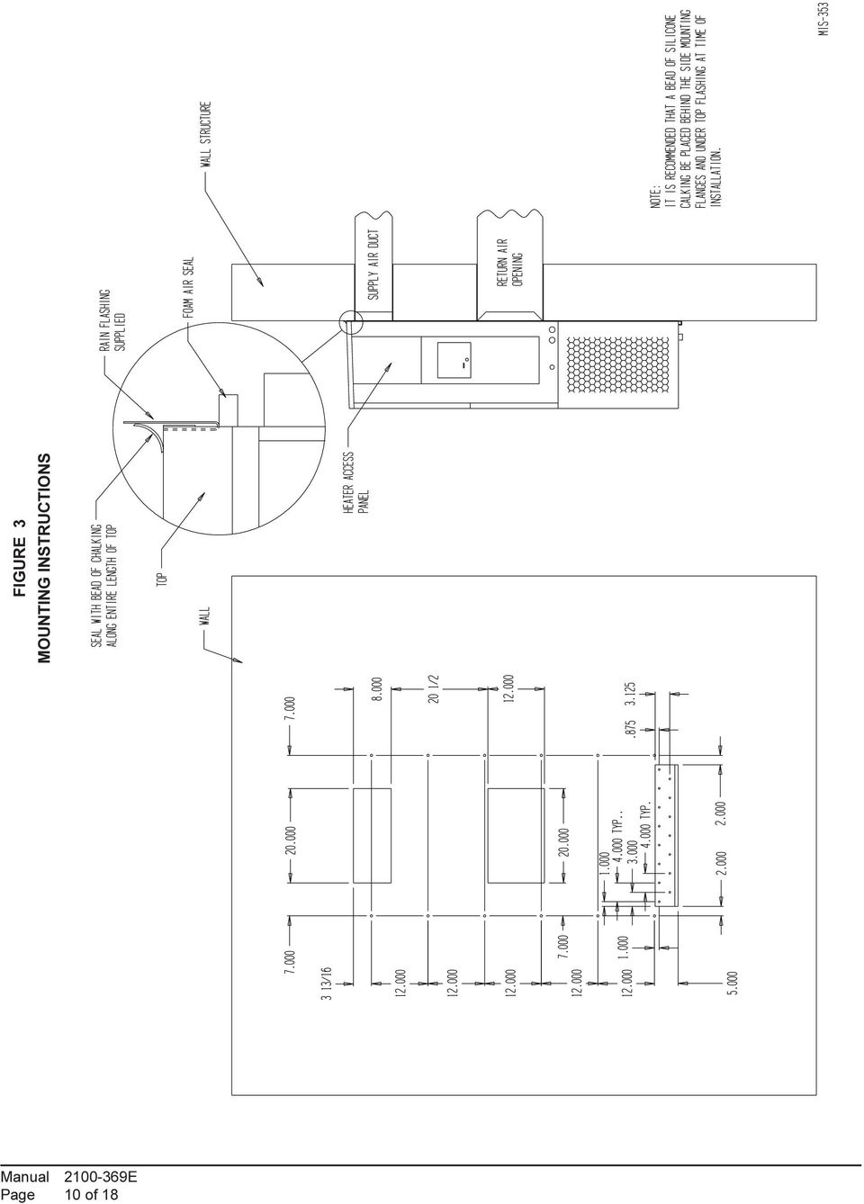
10 FIGURE 3 MOUNTING INSTRUCTIONS Page 0 of 8
11 FIGURE 4 WALL-MOUNTING INSTRUCTIONS SEE FIGURE 3 MOUNTING INSTRUCTIONS FIGURE 5 WALL-MOUNTING INSTRUCTIONS SEE UNIT DIMENSIONS, FIGURE, FOR ACTUAL DIMENSIONS SEE FIGURE FOR DUCT DIMENSIONS Page of 8

12 FIGURE 6 COMMON WALL-MOUNTING INSTALLATIONS Page 2 of 8

13 FIGURE 7 LOW VOLTAGE WIRING Page 3 of 8

14 START UP IMPORTANT INSTALLER NOTE For improved start-up performance, wash the indoor coil with a dishwasher detergent. CRANKCASE HEATERS All units are provided with some form of compressor crankcase heat. All single and three phase models have an insertion welltype heater located in the lower section of the compressor housing. This is a self-regulating type heater that draws only enough power to maintain the compressor at a safe temperature. Some form of crankcase heat is essential to prevent liquid refrigerant from migrating to the compressor, causing oil pump out on compressor start up and possible valve failure due to compressing a liquid. The decal in Figure 8 is affixed to all outdoor units detailing start up procedure. This is very important. Please read carefully. SERVICE HINTS. Caution homeowner to maintain clean air filters at all times. Also, not to needlessly close off supply and return air registers. This reduces airflow through the system, which shortens equipment service life as well as increasing operating costs. 2. Check all power fuses or circuit breakers to be sure they are the correct rating. 3. Periodic cleaning of the outdoor coil to permit full and unrestricted airflow circulation is essential. SEQUENCE OF OPERATION Cooling Circuit R-Y makes at thermostat pulling in compressor contactor, starting the compressor and outdoor motor. The G (indoor motor) circuit is automatically completed on any call for cooling operation or can be energized by manual fan switch on subbase for constant air circulation. On all 230 volt units there is a one-minute off delay on the blower motor. 460 volt models do not have an off delay. On a call for heating, circuit R-W make at the thermostat pulling in heat contact for the strip heat and blower operation. On a call for second stage heat, R-W2 makes bringing on second heat contactor, if so equipped. FIGURE 8 START UP LABEL IMPORTANT These procedures must be followed at initial start up and at any time power has been removed for 2 hours or longer. To prevent compressor damage which may result from the presence of liquid refrigerant in the compressor crankcase:. Make certain the room thermostat is in the "off" position (the compressor is not to operate). 2. Apply power by closing the system disconnect switch. This energizes the compressor heater which evaporates the liquid refrigerant in the crankcase. 3. Allow 4 hours or 60 minutes per pound of refrigerant in the system as noted on the unit rating plate, whichever is greater. 4. After properly elapsed time, the thermostat may be set to operate the compressor. 5. Except as required for safety while servicing, do not open system disconnect switch COMPRESSOR CONTROL MODULE The compressor control module is optional on the models covered by this manual. The compressor control is an anti-short cycle/lockout timer with high and low pressure switch monitoring and alarm relay output. Adjustable Delay On Make And Break Timer On initial power up or anytime power is interrupted to the unit, the delay on make period begins, which will be 2 minutes plus 0% of the delay on break setting. When the delay on make is complete and the high pressure switch (and low pressure switch if employed) is closed, the compressor contactor is energized. Upon shutdown the delay or break timer starts and prevents restart until the delay on break and delay on make periods have expired. During routine operation of the unit with no power interruptions the compressor will operate on demand with no delay. Page 4 of 8

15 High Pressure Switch and Lockout Sequence If the high pressure switch opens, the compressor contactor will de-energize immediately. The lockout timer will go into a soft lockout and stay in soft lockout until the high pressure switch closes and the delay on break time has expired. If the high pressure switch opens again in this same operating cycle the unit will go into manual lockout condition and the alarm relay circuit will energize. Recycling the wall thermostat resets the manual lockout. Low Pressure Switch, Bypass, and Lockout Sequence If the low pressure switch opens for more than 20 seconds, the compressor contactor will de-energize and go into a soft lockout. Regardless the state of the low pressure switch, the contactor will reenergize after the delay on make time delay has expired. If the low pressure switch remains open, or opens again for longer than 20 seconds the unit will go into manual lockout condition and the alarm relay circuit will energize. Recycling the wall thermostat resets the manual lockout. Alarm Relay Output Alarm terminal is output connection for applications where alarm relay is employed. This terminal is powered whenever compressor is locked out due to HPC or LPC sequences as described. NOTE: Both high and low pressure switch controls are inherently automatic reset devices. The high pressure switch and low pressure switch cut out and cut in settings are fixed by specific air conditioner or heat pump unit model. The lockout features, both soft and manual, are a function of the Compressor Control Module. ADJUSTMENTS Adjustable Delay on Make and Delay on Break Timer The potentiometer is used to select Delay on Break time from 30 seconds to 5 minutes. Delay on Make (DOM) timing on power-up and after power interruptions is equal to 2 minutes plus 0% of Delay on Break (DOB) setting: 0.5 minute (30 seconds) DOB =23 second DOM.0 minute (60 seconds) DOB =26 second DOM 2.0 minute (20 seconds) DOB =32 second DOM 3.0 minute (80 seconds) DOB =38 second DOM 4.0 minute (240 seconds) DOB =44 second DOM 5.0 minute (300 seconds) DOB =50 second DOM During routine operation of the unit with now power interruptions the compressor will operate on demand with no delay. Typical Settings for Dual Unit Installation: Unit No. : DOB set at 2 minutes, and DOM is 32 sec. Unit No. 2: DOB set at 4 minutes, and DOM is 44 sec. PRESSURE SERVICE PORTS High and low pressure service ports are installed on all units so that the system operating pressures can be observed. Pressure tables can be found later in the manual covering all models. It is imperative to match the correct pressure table to the unit by model number. Page 5 of 8

16 TROUBLESHOOTING FAN BLADE SETTING DIMENSIONS Shown in the drawing below are the correct fan blade setting dimensions for proper air delivery across the outdoor coil. Any service work requiring removal or adjustment in the fan and/or motor area will require that the dimensions below be checked and blade adjusted in or out on the motor shaft accordingly. FIGURE 9 FAN BLADE SETTING REFRIGERANT CHARGE The correct system R-22 charge is shown on the unit rating plate. Optimum unit performance will occur with a refrigerant charge resulting in a suction line temperature (6 inches from compressor) as shown in Table 6. Model TABLE 6 SUCTION LINE TEMPERATURES Rated 95 F OD 82 F OD Airflow Temperature Temperature WA WA The suction line temperatures in Table 6 are based upon 80ºF dry bulb/67ºf wet bulb (50 percent R.H.) temperature and rated airflow across the evaporator during cooling cycle. TABLE 5 FAN BLADE DIMENSION Model WA82 WA242 Dimension A.00 REMOVAL OF FAN SHROUD. Disconnect all power to unit. 2. Remove the screws holding both grills, one on each side of unit, and remove grills. 3. Remove screws holding fan shroud to condenser and bottom 9 screws. 4. Unwire condenser fan motor. 5. Slide complete motor, fan blade, and shroud assembly out the left side of the unit. 6. Service motor/fan as needed. 7. Reverse steps to reinstall. TABLE 7 INDOOR BLOWER PERFORMANCE CFM AT 230 VOLTS E.S.P. In H 2 O Dry WA82, Coil 230V WA242 Wet Coil Page 6 of 8
 as shown in Table 6.")
17 Model Rated CFM TABLE 8 CFM and ESP Rated ESP Rated CFM and ESP on high speed tap Recommended Airflow Range WA WA TABLE 9 MAXIMUM ESP OF OPERATION ELECTRIC HEAT ONLY Model WA82 WA242 WA242 KW A00 A05 A08 B00 B06 ESP TABLE 0 COOLING PRESSURE OUTDOOR TEMPERATURE F Model WA82 WA242 Return Air Temperature 75 deg DB 62 deg WB 80 deg DB 67 deg WB 85 deg DB 72 deg WB 75 deg DB 62 deg WB 80 deg DB 67 deg WB 85 deg DB 72 deg WB Pressure Low Side High Side Low Side High Side Low Side High Side Low Side High Side Low Side High Side Low Side High Side Low side pressure ± 2 psig High side pressure ± 5 psig Tables are based upon rated CFM (airflow) across the evaporator coil and should be found under section titled "refrigerant charge" elsewhere in manual. If there is any doubt as to correct charge being in the system, the charge should be removed, system evacuated and recharged to serial plate instructions. Page 7 of 8

18 TABLE OPTIONAL ACCESSORIES Model Description WA82-A WA242-A WA242-B WA242-C EHWA24-A04 Heater Packages X EHWA02-A05 Heater Packages X X EHWA02A-A08 Heater Packages X X EHWA02A-A0 Heater Packages X X EHWA24-B06 Heater Packages X BOP-2 Blank Off Plate BFAD-2 Barometric Fresh Air Damper MFAD-2 Motorized Fresh Air Damper CRV-2 Commercial Ventilator with Exhaust EIFM-2 Economizer with Exhaust WERV-A2B Energy Recovery Ventilator CMA-5 Time Delay Relay (TDR) CMA-6 Low Ambient Control (LAC) CMA-8 TDR + HPC CMA-0A LPC + HPC + TDR CMA-3A LPC + HPC + TDR + LAC CMC-5 Start Kit X X WMCB-02A Circuit Breaker Kit X X WMCB-0B Circuit Breaker Kit X EHWA24B-C06 WMPD-0C Heater Packages Circuit Breaker Kit X X Page 8 of 8

INSTALLATION INSTRUCTIONS WALL MOUNTED PACKAGE AIR CONDITIONERS
 INSTALLATION INSTRUCTIONS WALL MOUNTED PACKAGE AIR CONDITIONERS MODEL: WA121 Bard Manufacturing Company Bryan, Ohio 43506 Since 1914...Moving ahead, just as planned. Manual : 2100-234 E Supersedes: 2100-234
WALL MOUNTED PACKAGED AIR CONDITIONER INSTALLATION INSTRUCTIONS. Models: WA301, WA361. Bard Manufacturing Company Bryan, Ohio 43506
 INSTALLATION INSTRUCTIONS WALL MOUNTED PACKAGED AIR CONDITIONER Models: WA30, WA36 MIS-656 Bard Manufacturing Company Bryan, Ohio 43506 Since 94...Moving ahead just as planned. Manual No.: 20-92M Supersedes:
WALL MOUNTED PACKAGED WA372. Bard Manufacturing Company Bryan, Ohio 43506. Manual No.: 2100-404 Supersedes: File: Volume III, Tab 16 Date: 04-01-02
 WALL MOUNTED PACKAGED INSTALLATION AIR CONDITIONER INSTRUCTIONS Models: WA302 WA372 MIS-656 Bard Manufacturing Company Bryan, Ohio 43506 Since 94...moving ahead just as planned. Manual No.: 20-404 Supersedes:
INSTALLATION INSTRUCTIONS WALL MOUNTED PACKAGE AIR CONDITIONERS
 INSTALLATION INSTRUCTIONS WALL MOUNTED PACKAGE AIR CONDITIONERS MODELS WA WL W24A W24L WA WL W3A W3L W42A W42L W4A W4L WA WL Bard Manufacturing Company, Inc. Bryan, Ohio 40 Since 94...Moving ahead just
INSTALLATION INSTRUCTIONS WALL MOUNTED PACKAGE AIR CONDITIONERS
 INSTALLATION INSTRUCTIONS WALL MOUNTED PACKAGE AIR CONDITIONERS MODELS W7A2 W7L2 WA2 WL2 W24A2 W24L2 WA2 WL2 W3A2 W3L2 W42A2 W42L2 W4A2 W4L2 WA2 WL2 W70A2 W70L2 Bard Manufacturing Company, Inc. Bryan,
THE WALL-MOUNT ONE TON AIR CONDITIONER GREEN REFRIGERANT R-410A. 10,800 Btuh 9.00 EER Right Side Control Panel. Engineered Features
 THE WALL-MOUNT ONE TON AIR CONDITIONER W2A,800 Btuh 9.00 EER Right Side Control Panel 60Hz GREEN REFRIGERANT R-A The Bard Wall-Mount One Ton Air Conditioner is a self contained energy efficient heating
INSTALLATION INSTRUCTIONS COMMERCIAL ROOM VENTILATORS WITH EXHAUST
 INSTALLATION INSTRUCTIONS COMMERCIAL ROOM VENTILATORS WITH EXHAUST MODEL CHCRV-5 For Use with Bard CH Series 3, 4 & 5 Ton 2-Stage Wall Mount Heat Pumps AND W38H, W43H, W49H and W61H Single Stage Wall Mount
Models: WA182, WA242. Contents. Cabinet Components. Functional Components " Exploded View... 3 " Usage List... 4. Control Panel.
 REPLACEMENT PARTS MANUAL WALL MOUNTED PACKAGE AIR CONDITIONER Models: WA182, WA242 General Notes! Revised and/or additional pages may be issued from time to time.! A complete and current manual consists
WALL MOUNTED PACKAGE AIR CONDITIONER REPLACEMENT PARTS MANUAL W70A1 W70L1. Models: Contents. General Notes. Important. Description
 REPLACEMENT PARTS MANUAL WALL MOUNTED PACKAGE AIR CONDITIONER Models: W0A W0L General Notes Contents Revised and/or additional pages may be issued from time to time. A complete and current manual consists
THE WALL-MOUNT TM HEAT PUMPS - (60HZ)
") THE WALL-MOUNT TM HEAT PUMPS - (HZ) Models: WH2 to WH2 Hz Heating Capacities:, to 5, BTUH Cooling Capacities:, to 5, BTUH Green Refrigerant R-A The Bard Wall-Mount Heat Pump is a self-contained energy
THE WALL-MOUNT TM HEAT PUMPS - (HZ) Models: WH2 to WH2 Hz Heating Capacities:, to 5, BTUH Cooling Capacities:, to 5, BTUH Green Refrigerant R-A The Bard Wall-Mount Heat Pump is a self-contained energy
Models: Contents. Cabinet Components. Functional Components " Exploded View... 3 " Usage List... 4. Control Panel. Blower Housing
 REPLACEMENT PARTS MANUAL WALL MOUNTED PACKAGE HEAT PUMPS Models: WH301 WH361 General Notes! Revised and/or additional pages may be issued from time to time.! A complete and current manual consists of pages
WALL MOUNTED PACKAGE HEAT PUMPS REPLACEMENT PARTS MANUAL WH483 WH602. Contents. General Notes. Important. Description
 REPLACEMENT PARTS MANUAL WALL MOUNTED PACKAGE HEAT PUMPS Models: WH421 WH483 WH602 General Notes Contents Ø Ø Revised and/or additional pages may be issued from time to time. A complete and current manual
ModPac II 1 to 5-Ton Vertical Wall Mount Air Conditioners Models AVPA12-20-24-30-36-42-48-60
 ModPac II 1 to 5-Ton Vertical Wall Mount Air Conditioners Models AVPA12-20-24-30-36-42-48-60 General Description The Marvair ModPac II air conditioner is a vertical, wall mounted, cost effective air conditioner
INSTALLATION INSTRUCTIONS MC95HAE-1 MASTER CONTROLLER
 INSTALLATION INSTRUCTIONS MC95HAE-1 MASTER CONTROLLER Bard Manufacturing Company, Inc. Bryan, Ohio 43506 Since 1914...Moving ahead just as planned. Manual : 2100-360B Supersedes: 2100-360A File: Volume
SECTION 23 81 03 - PACKAGED ROOFTOP AIR CONDITIONING UNITS NON-CUSTOM
 SECTION 23 81 03 - PACKAGED ROOFTOP AIR CONDITIONING UNITS NON-CUSTOM PART 1 - GENERAL 1.1 SUMMARY A. Section Includes: 1. Packaged rooftop air conditioning unit (5 tons and smaller). 2. Roof curb. 1.2
E2 Series Electric Furnaces
 E2 Series Electric Furnaces Service Manual Table of Contents Electrical Requirements... 10 Codes, Specifications Requirements... 10 Connection Supply Service Wires... 10 Furnace Sequence of Operation...
Roof Top Air Conditioner INSTALLATION AND OPERATING INSTRUCTIONS
 Roof Top Air Conditioner INSTALLATION AND OPERATING INSTRUCTIONS Ducted System RECORD THIS UNIT INFORMATION FOR FUTURE REFERENCE: Model Number: Serial Number: Date Purchased: This manual must be read and
Heating, Ventilation, Air Conditioning and Refrigeration (HVACR)
") Heating, Ventilation, Air Conditioning and Refrigeration (HVACR) I. Demonstrate safety skills in typical HVACR work situations to NATE Core Installer Knowledge Areas for Technician Excellence for Safety
Heating, Ventilation, Air Conditioning and Refrigeration (HVACR) I. Demonstrate safety skills in typical HVACR work situations to NATE Core Installer Knowledge Areas for Technician Excellence for Safety
SERVICE MANUAL FOR 6535 SERIES TWO TON HIGH EFFICIENCY PACKAGED HEAT PUMPS
 SERVICE MANUAL FOR 6535 SERIES TWO TON HIGH EFFICIENCY PACKAGED HEAT PUMPS TABLE OF CONTENTS 1. Warnings...2 2. Accessibility Of Appliance...3 3. Unit Dimensions And Specifications...3 4. Unit Specifications
SWIMMING POOL HEAT PUMP
 SWIMMING POOL HEAT PUMP Installation & User Manual Model HP40B HP50B HP65B Hayward Pool Products Canada, Inc. T: 1-888-238-7665 www.haywardpool.ca CONTENT I. Application 4 II. Features 4 III. Technical
Oil and Coolant Circulating Heating System. Model - OCSM
 Oil and Coolant Circulating Heating System Model - OCSM Installation & Operation Manual 216280-000 REV 2 Identifying Your System The HOTSTART heating system is designed to heat fluids for use in marine
THE WALL-MOUNT AIR CONDITIONERS - WA (60HZ)
") THE WLL-MOUNT IR CONDITIONERS - W (HZ) W-SERIES Hz. to Ton (,3 to 7, Btuh) Right Side Control Panel Refrigerant The Bard Wall-Mount ir Conditioner is a self contained energy efficient system, which is
THE WLL-MOUNT IR CONDITIONERS - W (HZ) W-SERIES Hz. to Ton (,3 to 7, Btuh) Right Side Control Panel Refrigerant The Bard Wall-Mount ir Conditioner is a self contained energy efficient system, which is
Installation Instructions
 H5HK Series Installation Instructions 3 Phase Electric Heater Kits 7.5 and 0 TON Package A/C Systems Description Installation of 08/40V and 480V H5HK 3 Phase Heater Kits in 7.5 and 0 TON Packaged Air Conditioners.
THE WALL-MOUNT 6-TON AIR CONDITIONERS
 THE WLL-MOUNT -TON IR CONDITIONERS Model W7 - Right Side Control Panel Model W7L - Left Side Control Panel, Btuh 9. EER Hz The Bard Wall-Mount ir Conditioner is a self contained energy efficient system,
CELLU KOOL SERIES INSTALLATION OPERATION MAINTENANCE AND PARTS MANUAL COMPU AIRE INC. MODEL TYPE SIZE
 INSTALLATION OPERATION MAINTENANCE AND PARTS MANUAL CELLU KOOL SERIES MODEL TYPE SIZE CELHP HEAT PUMP 1 ½ TO 5 TON CELAC AIR CONDITIONER 1 ½ TO 5 TON COMPU AIRE INC. 8167 BYRON RD. WHITTIER, CA 90606 PH
CEILING CASSETTE FAN COIL UNIT
 CEILING CASSETTE FAN COIL UNIT Operation and Installation Manual MHCFC4W-04, 08, 12, 16 Four way ceiling cassette fan coil unit Please read this manual before using the fan coil unit. Installation and
SECTION 23 00 01 HEATING, VENTILATION AND AIR CONDITIONING EQUIPMENT
 SECTION 23 00 01 HEATING, VENTILATION AND AIR CONDITIONING EQUIPMENT PART 1 - GENERAL 1.1 DESCRIPTION A. The Work specified in this Section consists of designing, furnishing and installing factory-assembled
PACKAGE AIR CONDITIONERS REPLACEMENT PARTS MANUAL
 REPLACEMENT PARTS MANUAL PACKAGE AIR CONDITIONERS Models: P1142A3 P1148A1 P1148A1-B P1148A1-C P1060A1 P1060A1-B P1060A1-C P1148A1-A/H P1148A1-B/H P1148A1-C/H P1060A1-A/H P1060A1-B/H P106A1-C/H General
FOXAIR 60/50 ALL MODELS
 FOXAIR 60/50 ALL MODELS OPERATION AND SERVICE MANUAL UNIT WEIGHT - ALL MODELS APPROX. 300 POUNDS FOXTRONICS, INC. 38 L x 28 W x 24 H Love Field-Dallas TX MADE IN THE USA 3448 West Mockingbird Lane Dallas,
NewAir AC-10100E / AC-10100H Portable Air Conditioner Owner s Manual PLEASE READ AND SAVE THESE INSTRUCTIONS
 NewAir AC-10100E / AC-10100H Portable Air Conditioner Owner s Manual PLEASE READ AND SAVE THESE INSTRUCTIONS ELECTRICAL SAFETY This appliance is for indoor use only. Always turn off the unit and unplug
WINDOW ROOM AIR CONDITIONER
 WINDOW ROOM AIR CONDITIONER Installation and Operation Manual Electromechanical Remote Control CAPACITIES 220V - 60 HZ. 12,000; 18,000; 24000 BTU/HR 220V-240V - 50 HZ. 12,000; 18,000; 24000 BTU/HR Please
Central Air Conditioner
 Central Air Conditioner USER S INFORMATION MANUAL FOR THE OPERATION AND MAINTENANCE OF YOUR NEW RESIDENTIAL AIR CONDITIONER NOTE TO INSTALLER: THIS MANUAL MUST BE LEFT WITH THE EQUIPMENT USER. WELCOME
LOBOY 16 AIR CONDITIONERS
 INSTRUCTION MANUAL FOR: LOBOY 16 AIR CONDITIONERS McLean Midwest Corp. dba: McLean Cooling Technology 11611 Business Park Blvd. N Champlin, MN 55316 Tel: 763-323-8200 Fax: 763-576-3200 www.mcleancoolingtech.com
PROAIR Water-Cooled Air Conditioner. CR43WC Model INSTRUCTION MANUAL. Rev. E 2013 Pentair Technical Products P/N 10-1008-167
 PROAIR Water-Cooled Air Conditioner CR43WC Model INSTRUCTION MANUAL Rev. E 2013 Pentair Technical Products P/N 10-1008-167 87976466 TABLE OF CONTENTS HANDLING & TESTING THE AIR CONDITIONER...3 INSTALLATION
catalog Single Package Vertical Air Conditioners and Heat Pumps
 catalog Single Package Vertical Air Conditioners and Heat Pumps Catalog: SK145.00-EG1 (1008) TABLE OF CONTENTS Single Package Vertical Units Introduction...............................................................................
SINGLE PACKAGE VERTICAL AIR CONDITIONERS
 SINGLE PACKAGE VERTICAL AIR CONDITIONERS AIR CONDITIONERS l HEAT PUMPS l ELECTRIC HEAT QUIETER BY DESIGN SIMPLE TO INSTALL CONCEALED INSTALLATION www.friedrich.com VERT-I-PAK ideal for extended stay properties,
SECTION 15750 PACKAGED ROOFTOP AIR CONDITIONING UNITS
 SECTION 15750 PART 1 - GENERAL 1.01 DESCRIPTION A. Section includes requirements for roof mounted, self-contained units, with electric cooling, and electric or reverse refrigeration cycle (heat pump) heating
Please read this owner s Manual carefully before operating the unit. - Cooling - Heating - Dehumidifying - Fan
 Please read this owner s Manual carefully before operating the unit. - Cooling - Heating - Dehumidifying - Fan TABLE OF CONTENTS INTRODUCTION 2 IMPORTANT SAFEGUARDS...2 PACKAGE CONTAINS..2 NAMES OF PARTS.3
Cooktop Low-Profile Ventilation Hoods
 INSTALLATION GUIDE Cooktop Low-Profile Ventilation Hoods Contents Wolf Cooktop Low-Profile Ventilation Hoods........ 3 Cooktop Low-Profile Hood Specifications.......... 4 Cooktop Low-Profile Hood Installation............
INSTALLATION INSTRUCTIONS Fan Coil Replacement Coil Kit EBX & EBXX
 Fan Coil Replacement Coil Kit EBX & EBXX These instructions must be read and understood completely before attempting installation. These instructions covers the installation of replacement coil kit into
WMSLW / WMBLWH Series Hydronic Upflow/Horizontal Left or Right, Heating and Cooling Air Handler
 WMSLW / WMBLWH Series Hydronic Upflow/Horizontal Left or Right, Heating and Cooling Air Handler Installation Operation Maintenance The WMSLW/WMBLW series is designed for installation in a closet, utility
Service manual. Website: www.andico.com.au CAUTION - BEFORE SERVICING THE UNIT, READ THE SAFETY - PRECAUTIONS IN THIS MANUAL.
 Website: www.andico.com.au Service manual CAUTION - BEFORE SERVICING THE UNIT, READ THE SAFETY - PRECAUTIONS IN THIS MANUAL. - ONLY FOR AUTHORISED SERVICE PERSONNEL. MODELS: MPK1-09CR-QB8 MPK1-12ER-QB6
M SERIES REFRIGERANT COIL MODULE REFRIGERANT COILS for R-22, R-407C, R-410A
 Bulletin 20-20.2 / July 2012 M SERIES REFRIGERANT COIL MODULE REFRIGERANT COILS for R-22, R-407C, R-410A ➀ ➁ ➂ Model Number Key M 2430 C L 1 - A - ➀ Unit Type M=Modular Nominal Capacity 2430=24000 to 30000
Single Package Vertical Air Conditioners. Vert-I-Pak
 Single Package Vertical Air Conditioners Vert-I-Pak Installs easily in a closet for quiet operation and provides a more homelike appearance for your guests. THE EXPERTS IN ROOM AIR CONDITIONING A Better
USER MANUAL WARNING! CONTENTS MODEL 1 SPECIFICATIONS READ ALL INSTRUCTIONS BEFORE PROCEEDING. Non-Programmable Single Stage Heat/Cool Thermostat
 Builder MODEL 1010 Series Non-Programmable Single Stage Heat/Cool Thermostat USER MANUAL Compatible with low voltage single stage gas, oil or electric heating or cooling systems, including single stage
543-0032-00, 943-0032-00. User s Manual
 543-0032-00, 943-0032-00 User s Manual 1 Comfort Alert Diagnostics Faster Service And Improved Accuracy The Comfort Alert diagnostics module is a breakthrough innovation for troubleshooting heat pump and
Glossary of Heating, Ventilation and Air Conditioning Terms
 Glossary of Heating, Ventilation and Air Conditioning Terms Air Change: Unlike re-circulated air, this is the total air required to completely replace the air in a room or building. Air Conditioner: Equipment
Installation Instructions
 READ BEFORE INSTALLING UNIT For Slider Casement Air Conditioners To avoid risk of personal injury, property damage, or product damage due to the weight of this device and sharp edges that may be exposed:
MAC-120HE-01 Air-Cooled Chiller
 MAC-120HE-01 Air-Cooled Chiller 10 Ton / 120,000 BTUH Air-Cooled Chiller 208/230-1-50/60 1 HVAC Guide Specifications Air-Cooled Liquid Chiller Nominal Size: 10 Tons Multiaqua Model Number: MAC-120HE-01
USER S MANUAL HSC-24A
 AIRREX AIR CONDITIONER USER S MANUAL HSC-24A Thank you for purchasing an AIRREX AIR CONDITIONER. BEFORE operation please read this user s manual carefully. Keep this manual readily available. It is ESSENTIAL
ComPac I and ComPac II Air Conditioner Product Manual
 ComPac I and ComPac II Air Conditioner Product Manual Vertical Wall-Mount Air Conditioners with Front Control Box Panel Models AVP24-30-36-42-48-60-72 Chapter 1 Description... 5 Chapter 2 Installation...
Installation Instructions For Slider Casement Air Conditioners
 Installation Instructions For Slider Casement Air Conditioners NOTE: These instructions describe installation in a typical wood framed window with a wood SLIDE-BY sash, or installation in a metal CASEMENT
HEAT PUMP FREQUENTLY ASKED QUESTIONS HEAT PUMP OUTDOOR UNIT ICED-UP DURING COLD WEATHER:
 HEAT PUMP FREQUENTLY ASKED QUESTIONS HEAT PUMP OUTDOOR UNIT ICED-UP DURING COLD WEATHER: It is normal for a heat pump to have a build up of white frost on the outside coil during cold damp weather. The
Split System Heat Pump Product Data
 Split System Heat Pump Product Silver 14 4A6H4 1 1 /2-5 Tons PUB. NO. 12-1175-07 Contents Features and Benefits 2 Model Nomenclature 3 General 4 Product Specifications 4 A-weighted Sound Power Level [db(a)]
Installation Instructions
 VentilAire IV Whole-House Fresh Air Supply System Installation Instructions 914228 Flat Roof Kit 914229 Sloped Roof Kit 5" x 11' Class I Insulated Flexible Duct Plastic Clamps (2) Metal Clamps (2) Ceiling
SECTION 11 78 13 MORTUARY REFRIGERATORS
 PART 1 - GENERAL 1.1 DESCRIPTION SECTION 11 78 13 MORTUARY REFRIGERATORS SPEC WRITER NOTE: Delete between //---// if not applicable to project. Also delete any other item or paragraph not applicable in
Name of Equipment Silver King Model SKMCD1P/C1. This equipment chapter is to be inserted in the appropriate section of the Equipment Manual.
 Name of Equipment Silver King Model SKMCD1P/C1 This equipment chapter is to be inserted in the appropriate section of the Equipment Manual. Manufactured exclusively for McDonald s By Silver King Refrigeration,
HP 5 Microprocessor Control for Mammoth Water Source Heat Pumps
 HP 5 Microprocessor Control for Mammoth Water Source Heat Pumps Operation and Maintenance Manual Model: 71028004 Applies to: Single Circuit Water-to-Water Twin Circuit Units Without DDC Controls MAMM WHSP
Portable Air Conditioner. OWNER S MANUAL Read these instructions before use. Model: MM14CHCSCS
 Portable Air Conditioner OWNER S MANUAL Read these instructions before use Model: MM14CHCSCS Voltage rating: 120V~60Hz Power rating : 1400W(Cooling) Power rating : 1350W(Heating) Customer Support : 1-800-474-21477
M7RL Series TECHNICAL SPECIFICATIONS. FEATURES and BENEFITS. High Efficiency / Direct Vent Condensing Downflow Gas Furnace
 TECHNICAL SPECIFICATIONS M7RL Series High Efficiency / Direct Vent Condensing Downflow Gas Furnace Induced Draft - 9%+ AFUE Input 4,000 thru 7,000 Btuh The high efficiency downflow gas furnace is especially
Air Conditioning Sign-Off Sheet
 Air Conditioning Sign-Off Sheet Printed Technician Name Address Social Security Number Telephone Number City State Zip Code Install Or Verify The Accuracy Of An Air Conditioner s Installation The candidate
USER INSTRUCTIONS FOR GET PORTABLE 12k BTU AIR CONDITIONER MODEL No. GPACU12HR
 USER INSTRUCTIONS FOR GET PORTABLE 12k BTU AIR CONDITIONER MODEL No. GPACU12HR CONTENTS Introduction Safety Notes Identification of parts Installation instructions Operation instructions Maintenance Troubleshooting
Product Data. Split System Cooling 22-1904-1F-EN. March 2015
 Product Data Split System Cooling 4TTR4018L1000A 4TTR4024L1000A 4TTR4025L1000A 4TTR4030L1000A 4TTR4031L1000A 4TTR4036L1000A 4TTR4037L1000A 4TTR4042L1000A 4TTR4043L1000A 4TTR4048L1000A 4TTR4060L1000A Note:
Single Zone LCD Thermostat Operating Instructions
 Fan Cool Furnace *Heat Pump or Heat Strip On/Off F Single Zone LCD Thermostat Operating Instructions MODEL 3313192.XXX Cool/Furnace 3313193.XXX Cool/Furnace/Heat Pump 3313194.XXX Cool/Furnace/Heat Strip
WON0502-B INSTALLATION INSTRUCTIONS FOR ELECTRIC FURNACES. Bulletin 30-34 / March 2013
 Bulletin 30-34 / March 2013 INSTALLATION INSTRUCTIONS FOR ELECTRIC FURNACES General The information on the following pages is to provide the installer the necessary information to properly install the
UNIVERSITY OF MISSOURI 23 0000 - Heating Ventilating and Air-Conditioning (HVAC) March 2015.01
 March 2015.01") GENERAL: This section provides general standards for overall sizing and design of Heating, Ventilating, and Air Conditioning (HVAC) systems. Other sections contain specific standards for each system per
GENERAL: This section provides general standards for overall sizing and design of Heating, Ventilating, and Air Conditioning (HVAC) systems. Other sections contain specific standards for each system per
Low Profile Unit Cooler
 Super-Flo Now available with EC Motors High Efficiency / High Reliability Low Profile Unit Cooler Publication No. 411.4 November, 2008 S A N I T A T I O N F O U N D A T I O N A L N A T I O N Air Defrost
INSTALLATION INSTRUCTIONS HOT GAS BYPASS SYSTEM DESIGN MANUAL
 INSTALLATION INSTRUCTIONS HOT GAS BYPASS SYSTEM DESIGN MANUAL MODELS: WA/WL44H WA/WLH WA/WL70*H NOTE: Electrical data presented in this manual supersedes any other data f the above listed models. Bard
UHIR Series. Horizontal or Vertical Mounting Industrial / Commercial Electric Unit Heater. Owner s Manual
 UHIR Series Horizontal or Vertical Mounting Industrial / Commercial Electric Unit Heater Owner s Manual This manual covers installation, maintenance and repair parts. Read carefully before attempting to
ICE AIR. Console Water Source Heat Pump (WSHP) OPERATING & MAINTENANCE MANUAL. Wo r l d C l a s s C o m f o r t. www.ice-air.com
 OPERATING & MAINTENANCE MANUAL. Wo r l d C l a s s C o m f o r t. www.ice-air.com") 80 Hartford Avenue Mount Vernon New York 10553 Tel: 914-668-4700 EXT. 203 Fax: 914-668-5643 www.ice-air.com Wo r l d C l a s s C o m f o r t Console Water Source Heat Pump (WSHP) OPERATING & MAINTENANCE
80 Hartford Avenue Mount Vernon New York 10553 Tel: 914-668-4700 EXT. 203 Fax: 914-668-5643 www.ice-air.com Wo r l d C l a s s C o m f o r t Console Water Source Heat Pump (WSHP) OPERATING & MAINTENANCE
REFRIGERATED TYPE COMPRESSED AIR DRYERS INSTRUCTION MANUAL. For Sales & Service please contact:
 7610.478.16 8/99 INSTRUCTION MANUAL Models 8005, 8010, 8015 For Sales & Service please contact: CENTRAIR Air Systems & Supplies Phone: 705-722-5747 Fax: 705-722-5458 Email: sales@centrair.ca Website: www.centrair.ca
ARMSTRONG AIR HEAT PUMPS www.armstrongair.com
 INDEX ELECTRIC FURNACE MODULAR AIR SYSTEM EFC/EFV... 5-10 electric Heat Kits... 5-11 evaporator coils EC1P / EM1P UPFLOW / COUNTERFLOW APPLICATIONS and upflow / horizontal applications (CASED)... 5-6 5-7
SECTION 23 81 43 HEAT PUMPS
 SECTION 23 81 43 HEAT PUMPS PART 1 GENERAL 1.1 SUMMARY A. Section Includes: 1. Packaged rooftop heat pumps. 1.2 REFERENCES A. American Society of Heating, Refrigerating and Air-Conditioning Engineers:
Portable Air Conditioner
 Portable Air Conditioner Owner's Manual Model:3 in 1 12,000 Btu/h Series 3 Please read this owner s manual carefully before operation and retain it for future reference. CONTENTS 1. SUMMARY...1 2. PORTABLE
G26 Corp. 9721-L11 Revised 07-2001 LENNOXOEMPARTS.COM. Service Literature G26 SERIES UNITS
 Service Literature G26 SERIES UNITS G26 series units are high-efficiency upflow gas furnaces manufactured with DuralokPlust aluminized steel clamshell-type heat exchangers. G26 units are available in heating
Air Conditioning System
 Owner s Information Manual Air Conditioning ystem NOTE TO EQUIPMENT OWNER: For your convenience, please record the model and serial numbers of your new equipment in the space provided. This information,
Split System Cooling Product Data
 Split System Cooling Product XL16i 1½ 5 Tons PUB. NO. 22-1890-01 Features and Benefits Climatuff compressor Efficiency up to 16.0 SEER and 9.0 HSPF All aluminum Spine Fin coil WeatherGuard fasteners Quick-Sess
SECTION 15732 AIR CONDITIONING UNIT
 SECTION 15732 AIR CONDITIONING UNIT PART 1 GENERAL 1.01 SUMMARY A. Section includes: 1. Packaged, split system air conditioning unit No. 1. 1.02 REFERENCES A. Air-Conditioning, Heating, and Refrigeration
VertiCool Space Saver 2 to 15 tons Water-Cooled and Chilled Water
 2 to 15 tons Water-Cooled and Chilled Water Unique Solutions for Challenging HVAC Projects Your Choice for Limited Space Applications Water-Cooled Chilled Water The VertiCool Space Saver allows installation
Portable Air Conditioner. OWNER S MANUAL Read these instructions before use. Model: MF08CESWW. Voltage rating: 115V~60Hz Power rating : 800W
 MODE ALARM Portable Air Conditioner OWNER S MANUAL Read these instructions before use 8 Model: MF08CESWW Voltage rating: 115V~60Hz Power rating : 800W Customer Support : 1-800-474-2147 For product inquiries
Miami Heat Pump HP Series Installation Guide
 CAUTION- THIS UNIT IS FOR INDOOR USE ONLY!! WARNING BEFORE ANY INSTALLATION OR MAINTANCE IS STARTED PLEASE READ COMPLETE INSTLLATION GUIDE. INSTALLATION START-UP AND SERVICE INSTRUCTION- The HP Water Source
TECHNICAL MANUAL GDS8 & GHS8
 TECHNICAL MANUAL AL GDS8 & GHS8 33-3/8" 80% Gas Furnace Units Refer to Service Manual RS6610004 for installation, operation, and troubleshooting information. All safety information must be followed as
TECHNICAL & SERVICE MANUAL WINDOW TYPE AIR CONDITIONER SA 79G SA 99G FILE NO. SA 79G SA 99G REFERENCE NO. SM700402
 TECHNICAL & SERVICE MANUAL SA 79G SA 99G FILE NO. WINDOW TYPE AIR CONDITIONER Model No. Product Code No. Destination SA-79G-A 1 851 005 18 General (50Hz) & Europe SA-99G-A 1 851 005 19 SA 79G SA 99G REFERENCE
Install Guide CT100. Caution. Caution ENGLISH. disconnect the power supply before beginning work.
 Install Guide CT100 PG 1 Caution top cover Your thermostat is a precise instrument, handle it with care. Turn off electricity to the system before installing or servicing thermostat or any part of the
specializing in AIR CONDITIONING, PARTS AND SYSTEMS for your classic vehicle PERFECT FIT IN-DASH HEAT/ COOL/ DEFROST 1967-72 CHEVROLET PICKUP
 specializing in AIR CONDITIONING, PARTS AND SYSTEMS for your classic vehicle PERFECT FIT IN-DASH HEAT/ COOL/ DEFROST 1967-72 CHEVROLET PICKUP CONTROL & OPERATING INSTRUCTIONS The controls on your new Perfect
Split System Cooling Product Data
 Split System Cooling Product Data 4TTB3018-060 1½ 5 Tons PUB. NO. 22-1843-14 Features and Benefits Efficiency up to 13.25 SEER All aluminum Spine Fin coil WeatherGuard fasteners Quick-Sess cabinet, easy
Air Conditioner Water Heater - A Product of HotSpot Energy LLC
 Air Conditioner Water Heater - A Product of HotSpot Energy LLC PLEASE READ THIS BEFORE YOU INSTALL THE UNIT 1. This air conditioner must be installed and/or repaired by a qualified technician. If you perform
USER S, MAINTENANCE and SERVICE INFORMATION MANUAL
 CONTENTS SAFETY INFORMATION................ 2 FOR YOUR SAFETY....................... 2 SYSTEM OPERATION.................. 2 THERMOSTATS........................... 2 INTERMITTENT IGNITION DEVICE...........
BC & BCH SERIES INDOOR / OUTDOOR INSTALLATION
 Air Conditioning Central Heating & Cooling BC & BCH SERIES INDOOR / OUTDOOR INSTALLATION INSTALLATION AND SERVICE MANUAL 2 PROJECT: ADDRESS: MODEL: SERIAL NUMBER: INSTALLER: ADDRESS: PHONE NUMBER: INSTALLATION
Table Z. Troubleshooting Chart for Air Conditioners. Cause
 Troubleshooting Chart for Air Conditioners Type of Unit Complaint Cause With open-type compressor Electric motor will not start Power failure Check circuit for power source Compressor stuck Locate cause
NewAir AC-10000E, AC-10000H Portable Air Conditioner Owner s Manual PLEASE READ AND SAVE THESE INSTRUCTIONS
 NewAir AC-10000E, AC-10000H Portable Air Conditioner Owner s Manual PLEASE READ AND SAVE THESE INSTRUCTIONS BEFORE USE GENERAL SAFETY INSTRUCTIONS: ALWAYS OPERATE THE UNIT IN AN UPRIGHT POSITION AND PLACE
Heat Pump USER S INFORMATION MANUAL FOR THE OPERATION AND MAINTENANCE OF YOUR NEW RESIDENTIAL HEAT PUMP
 Heat Pump USER S INFORMATION MANUAL FOR THE OPERATION AND MAINTENANCE OF YOUR NEW RESIDENTIAL HEAT PUMP NOTE TO INSTALLER: THIS MANUAL MUST BE LEFT WITH THE EQUIPMENT USER. WELCOME TO EFFICIENT YEAR-ROUND
ESPD8-301R MODEL ESP-D FAN COIL UNIT TROUBLESHOOTING GUIDE
 ESPD8-301R MODEL ESP-D FAN COIL UNIT TROUBLESHOOTING GUIDE Protected by one or more of the following U.S. Patents (3,507,354; 3,575,234; 3,596,936; 3,605,797; 3,685,329; 4,045,977; 4,698,982; 926,673 and
AIR CONDITIONER & HEAT PUMP DIGITAL CONTROL FOR DUCTED SYSTEM INSTALLATION AND OPERATING INSTRUCTIONS
 AIR CONDITIONER & HEAT PUMP DIGITAL CONTROL FOR DUCTED SYSTEM INSTALLATION AND OPERATING INSTRUCTIONS FOR AC135, AC150, AC135HP, AC150HP, ACRG12, ACTH12 RECORD THIS UNIT INFORMATION FOR FUTURE REFERENCE:
NSN 4120-01-21 4-3692
 *TM 9-4120-388-14 TECHNICAL MANUAL Operator s, Unit, Direct Support, And General Support Maintenance Manual AIR CONDITIONER, VERTICAL, COMPACT, 18,000 BTU/HR 208 VOLT, 3 PHASE, 50/60 HERTZ NSN 4120-01-21
Portable Air Conditioner. OWNER S MANUAL Read these instructions before use. Model: MN12CES / MN10CESWW
 Portable Air Conditioner OWNER S MANUAL Read these instructions before use 8 Model: MN12CES / MN10CESWW Voltage rating: 120V~60Hz Power rating : 1100W (MN12CES) Power rating : 900W (MN10CESWW) Customer
Innovent LASER Packaged Fresh Air Conditioning Units
 LASER Latent And Sensible Energy Reduction Latent And Sensible Energy Reduction For Outside Air Innovent LASER Packaged Fresh Air Conditioning Units Innovent LASER units provide both sensible and latent
Cooling Capacity CFM range @.5 in. w.c. (125 Pa)
") N8MXL Product Specifications 80% ECM Single Stage Heating Furnace EASIER TO SELL 80% AFUE Flame roll out sensors standard Category I venting Blocked vent switch 24 VAC humidifier terminal Electronic air
N8MXL Product Specifications 80% ECM Single Stage Heating Furnace EASIER TO SELL 80% AFUE Flame roll out sensors standard Category I venting Blocked vent switch 24 VAC humidifier terminal Electronic air
CENTRAL AIR CONDITIONER A GUIDE TO OPERATING AND MAINTAINING YOUR RESIDENTIAL AIR CONDITIONING UNIT.
 CENTRAL AIR CONDITIONER A GUIDE TO OPERATING AND MAINTAINING YOUR RESIDENTIAL AIR CONDITIONING UNIT. NOTE TO INSTALLER: THIS MANUAL SHOULD BE LEFT WITH THE EQUIPMENT USER. WELCOME TO EFFICIENT HOME COOLING
INSTALLATION INSTRUCTIONS
 2008 Lennox Industries Inc. Dallas, Texas, USA WARNING Improper installation, adjustment, alteration, service or maintenance can cause property damage, personal injury or loss of life. Installation and