The 1250 MWe Boiling Water Reactor
|
|
|
- Beryl Shaw
- 10 years ago
- Views:
Transcription
1 The 1250 MWe Boiling Water Reactor

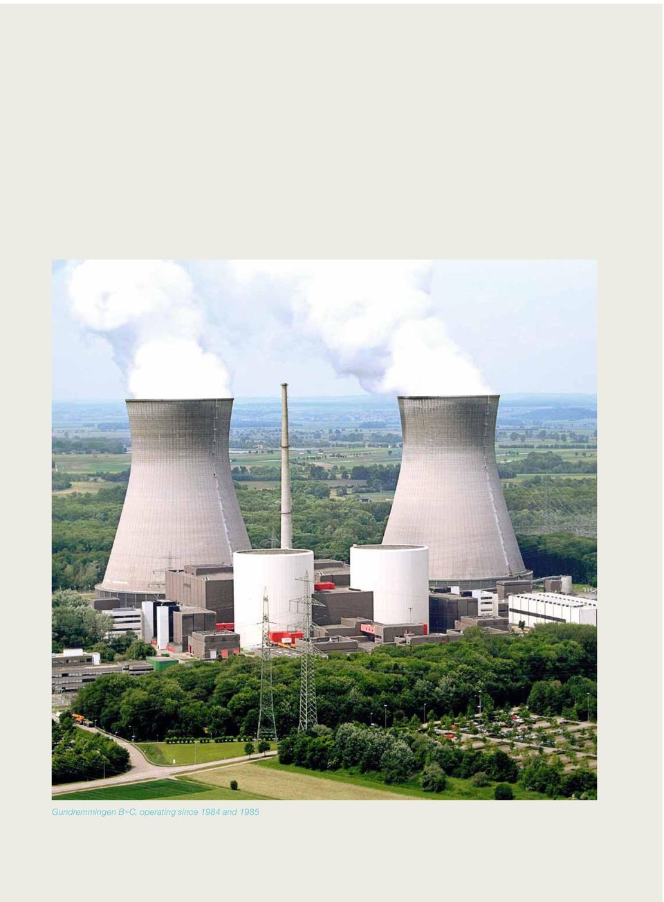
2 Gundremmingen B+C, operating since 1984 and 1985
3 3 The need to secure long-term energy supplies, stabilize energy costs and combat global warming, argues in favor of a wide and diverse energy mix. In this context, nuclear power, which is proving increasingly competitive, safe, reliable and environmentally friendly electricity, has a vital role to play. All over the world, areva supplies its customers with solutions for carbon-free power generation. With its knowledge and expertise in these fields, the group has a leading role in meeting the world s energy needs. Ranked first in the global nuclear power industry, areva s unique integrated offering covers every stage of the fuel cycle, reactor design and construction as well as related services. In addition, the group is expanding its operations in renewable energies, notably offshore wind, biomass and concentrated solar power. The KERENA TM reactor is areva s Generation III+BWR (Boiling Water Reactor). It is designed to meet the needs of electrical utilities with a preference for boiling water reactor technology and for customers interested in the 1250 MWe power output range. It is based on the evolution of BWR technology in Germany, especially the Gundremmingen plants, and developed in close cooperation with reference utilities including E.ON, RWE, EnBW, Vattenfall (Germany), EdF (France), TVO (Finland), along with technical institutes Technical Research Centre of Finland, Paul Scherrer Institute (Switzerland), Forschungszentrum Jülich (Germany) and Nuclear Research & Consultancy Group (Netherlands). The KERENA reactor benefits from E.ON s support for the completion of the basic design. E.ON holds shares in twelve BWRs across Europe and brings comprehensive, long-standing operating experience and technical expertise to the undertaking. The KERENA TM reactor offers competitiveness and flexibility in operation, together with an optimal redundant and diverse mix of BWR active and passive safety systems, while leveraging areva s design, construction and licensing experience.

4 KERENA TM : The Boiling Water Reactor by AREVA The KERENA TM reactor blends years of experience in design, construction and operation of BWRs with carefully considered new concepts, to achieve an optimum blend of increased safety and reduced costs. It has been developed with the input of reference nuclear operators to provide a safe and reliable source of economically competitive electricity. Proven Design Concept The basic design concept of the KERENA TM reactor as well as the systems and components provided for plant operation are based on the extensive and comprehensive experience gained from areva s operating boiling water reactors. Operating experience from existing BWR plants has been applied to simplify systems engineering for the KERENA TM reactor allowing to streamline the design: ÎÎSimple passive safety systems ÎÎThree main steam lines ÎÎTwo feedwater lines Balanced Active and Passive Gen III+Safety In addition to optimizing systems already present in current BWRs, the KERENA TM design is characterized by an innovative approach that entails active safety features combined with redundant and diverse passive safety. These utilize basic laws of nature, such as gravity and heat transfer, enabling passive systems to function without electrical power supply or actuation by instrumentation and control (I&C) or manually. The new concepts, for example, provide passive protection of the core without external intervention for up to three days after the onset of an event, while minimizing costs and system complexity. Competitive Power Generation Costs Total capital investment is reduced through simpler design compared to operating BWRs. Operation and maintenance are optimized through: ÎÎMaximized power output: 92% availability design target ÎÎExcellent load follow capabilities ÎÎLess maintenance due to fewer components, systems and structures ÎÎFewer operating personnel necessary on site Innovative Features Demonstrated by Full-scale Tests In parallel with the basic design phase, the function and effectiveness of KERENA TM s passive safety systems are experimentally verified. A comprehensive testing program, today already in a mature stage, is conducted at areva s testing facilities and at partner research centers in Switzerland and Germany. The Fuel Cycle costs are decreased through 37% efficiency design target, discharge burnups of up to 65 MWd/kgU, MOX ability of up to 50%, and the use of flow variation to improve fuel utilization (spectral shift).

5 5 Isar 1, operating since 1979 KERENA TM full-scale test facility in Karlstein

6 Part of a Value Added Reactor Portfolio The KERENA TM reactor combines a unique set of BWR specific characteristics with the common benefits of the full areva reactor portfolio. areva s range is designed to meet the full breadth of its clients needs, from the introduction to nuclear power to the industrial production of competitive and clean electricity. AREVA offers a portfolio of three nuclear reactor models: EPR, ATMEA1 and KERENA. These are latest generation (III+) pressurized and boiling water reactors, designed to enable electricity providers to achieve their competitiveness, safety and power generation capacity objectives. Performance & Profitability ÎÎMaximized plant availability: design target above 92% ÎÎHigh plant efficiency: design target 37% ÎÎLow O&M costs ÎÎLoad follow mode & frequency control Certainty & Predictability ÎÎMaximized standardization for reliable project implementation ÎÎContinuous engineering and manufacturing experience ÎÎExtensive in-house manufacturing capabilities ÎÎAn expanding international supply chain ÎÎUnique worldwide licensing experience, from Europe and the US to China Outstanding Safety ÎÎDesigned against the most stringent licensing requirements (Germany, France, Finland ) ÎÎLarge commercial airplane crash resistance ÎÎAdvanced severe accident management ÎÎSafety systems with multiple redundancy and diversity to prevent any adverse impact to the environment Environmental Protection ÎÎCO 2 -free power generation ÎÎReduced natural resources consumption ÎÎReduced collective dose ÎÎLess final waste through high efficiency and recycling
 pressurized and boiling water reactors, designed to enable electricity providers to achieve their competitiveness, safety and power generation capacity objectives.")
7 7 AREVA product range Developed with MHI 1250 MWe BWR 1100 MWe PWR 1650 MWe PWR Boiling Water Reactor Medium power output Market launch: 2010 Pressurized Water Reactors High power output Deployed

8 Boiling Water Reactor Technical Overview Reactor building Feedwater steam cycle 1 Reactor pressure vessel with reactor core 2 Reactor water recirculation pumps 3 Turbine 4 Moisture separator/reheater Cooling water circulation 5 Condenser 6 Main condensate pump 7 Feedwater preheater 8 Feedwater storage tank (optional) 9 Feedwater pump 10 Cooling tower (optional) 11 Circulation water pumps Power generation 12 Generator 13 Generator transformer 1 Saturated steam Main feed water
 11 Circulation water pumps Power generation 12 Generator 13 Generator transformer 1 Saturated steam Main feed")
9 9 KERENA Concept Description The plant is equipped with a boiling water reactor to generate steam at a thermal output of 3370 MWth. Saturated steam, at 7.5 MPa, is routed through the HP turbine and the moisture separator/reheater to the LP turbine. The net electrical output is approximately 1250 MWe. The steam leaving the lowpressure turbine sections is condensed in the main condensers. The condensate is returned to the reactor by condensate and feedwater pumps via the feedwater heating train. Turbine building Electrical energy 5 Circulation water 6 11 Condensate 10 Cooling air Cooling tower and feedwater storage tank are site dependent/optional Cooling water

10 Main plant data Overall plant Thermal output MWth 3370 Net electric output MWe 1250 Efficiency % 37 Plant design targets Availability % 92+ Power Density kw/l 51 Linear Power W/cm 127 Reactor core No. of fuel assemblies ATRIUM Total uranium weight Mg Active height of core m 3.0 Average power density kw/l 51.3 Discharge burnup GWd/t 65 Average enrichment % 4.68 Coolant flow rate kg/s Reactor pressure Vessel Inside height m Inside diameter m 7.12 Operating pressure bar 75 Design pressure bar 88 No. of recirculation pumps 8 Systems for Reactor shutdown Hydraulic scram system, fine-motion control rod drives, fast-acting boron injection system RPV pressure relief and depressurization Core flooding Residual heat removal Initiation of reactor scram, containment isolation and RPV depressurization 8 safety-relief valves, each with spring-loaded, diaphragm and solenoid pilot valves Active: 2 low-pressure RHR/coolant injection systems Passive: 4 flooding lines Active: 2 low-pressure RHR/coolant injection systems Passive: 4 emergency condensers 4 containment cooling condensers Active: reactor protection system Passive: passive pressure pulse transmitters

11 Boiling Water Reactor Vessel Head Handling 11

12 Table of contents 03 The KERENA TM Reactor 25 Containment and internals 09 KERENA TM Technical Overview 29 KERENA TM Safety Concept 15 KERENA TM PLANT Layout 41 Electrical and I&C Systems Concept 19 Nuclear Steam Supply System

13 13 47 Plant Operation, Maintenance and Services 53 EnvirONmental Impact

14 KERENA TM PLANT Layout

15 16 Reactor Building 17 unit control room building 17 reactor auxiliary building 17 reactor supporting systems building 17 turbine building 15 KERENA TM Containment Close-up

16 KERENA TM Reactor Layout Low level activity ÎÎWaste water treatment systems Protection against Earthquake Airplane crash Full Protection Physical Separation, Wreckage, Fire Turbine Building (5) Reactor Auxiliary Building (3) Reactor building (1) Unit Control Room Building (2) Diesel & Cooling Water System Buildings Diesel and Safety- Related Cooling Water System Buildings Unit Control Room Building (2) Reactor Building (1) Reactor Supporting System Building (4) Low level activity ÎÎStores ÎÎSafety-related I&C and switchgear ÎÎMain control room High & medium level activity ÎÎCore, spent fuel ÎÎRWCU, filter waste storage ÎÎOffgas adsorbers ÎÎSafety systems Diesel and Safety- Related Cooling Water System Buildings 1 Reactor Building The reactor building houses the containment, the safety-related mechanical components and the required support and protection systems. It provides protection against natural and manmade external hazards and ensures activity retention in the event of accidents. The structural concept is divided into three parts, as follows ÎÎOuter shell with penetration protection ÎÎInner structure, which is largely decoupled from the outer shell ÎÎContainment, whose structures are decoupled from the outer shell except via the base plate.

17 Circulation water inlet culvert 17 Quay 2 Switchyard Circulation water outfall culvert Reactor Building 2 Unit Control Room Building 3 Reactor Auxiliary Building 4 Reactor Supporting Systems Building 5 Turbine Building Nuclear Island Turbine Island Balance of Plant 2 Unit Control Room Building The unit control room building contains the main control room and the safety control center, as well as the related switchgear, I&C and HVAC equipment. The building is APC protected and the inner structure is completely decoupled from the outer shell, except via the base slab. 3 Reactor Auxiliary Building The reactor auxiliary building contains systems and components for the treatment and storage of radioactive wastewater, including the evaporator system. The selected arrangement of the liquid waste storage and processing system ensures short piping connections with the system and equipment areas in the turbine building and the reactor building. 4 Reactor Supporting Systems Building The reactor supporting systems building contains the hot workshops and parts of the waste processing and storage system, as well as the central access point to the controlled area. This building houses components of the following systems: ÎÎIntake and exhaust air system ÎÎSanitary facilities, changing rooms ÎÎLaboratory ÎÎHot workshop and decontamination facilities ÎÎReserved space for mobile concentrate treatment with a drum store for low-active waste 5 Turbine Building The turbine building contains mainly the systems and components of the steam, condensate and feedwater cycle, with condensate and feedwater pumps and feedwater preheaters as well as the turbine and generator. The turbine building is part of the controlled area of the plant.

18 NUCLEAR STEAM SUPPLY SYSTEM

19 20 Reactor Pressure Vessel and Internals 22 Reactor Core and Fuel Assemblies 22 Reactor Water Recirculation Pumps 22 Control Rod Drives 23 Steam, Condensate and Feedwater Cycle 19 Single Platform for Fuel Loading and Maintenance

20 Nuclear Steam Supply System The nuclear steam supply system is located in the reactor building and is surrounded by a steelreinforced concrete containment equipped with a steel liner. Reactor Pressure Vessel and Internals The reactor pressure vessel (RPV) encloses the reactor core and the RPV internals. The main dimensions of the RPV are comparable to those of a 1300 MWe BWR. As a result of this large volume, and due to the low positioning of the core inside the RPV, core uncovery does not occur in the event of automatic depressurization, even without coolant makeup. The core shroud as well as the upper and lower core grids mainly serve to align the core, the control rods, the in-core instrumentation and to guide core flow. Steam separators and steam dryers are installed in the RPV to separate the steam-water mixture leaving the core. A chimney is located between the core and the steam separators. All RPV internals are designed to allow removal and replacement as needed. The RPV is supported by a support skirt mounted around the top half of the RPV. The RPV internals, such as the core shroud, upper and lower core grid, steam separators and steam dryers, for example, are essentially based on the proven technology used in areva s 1300 MWe BWR design.

21 Boiling Water Reactor Plant Refuelling 21
22 Reactor Core and Fuel Assemblies The KERENA TM core represents an evolutionary development of previous standard BWR core designs. While no fundamental changes have been made to the basic structure of the BWR core design, certain modifications have been introduced. These modifications include reducing the active height of the core and increasing the size of the fuel assemblies. By reducing the active core height, the core can be positioned lower inside the RPV. As a result, there is a greater water inventory available inside the RPV above the core, which facilitates transient control. The aforementioned modification of the fuel assemblies consists of enlarging the existing ATRIUM TM 10 fuel assembly design (10x10-9Q) to a ATRIUM TM 12 fuel assembly (12x12-16Q). Fuel rod diameter and pitch, on the other hand, remain unchanged from the ATRIUM TM 10 fuel assembly. As a result of this new design, there are fewer core fuel assemblies. This reduces handling times during refueling and also reduces the number of control rods and control rod drives. Flexible operating cycles are planned for the KERENA TM plant. For example, the core can be operated in cycles lasting from 12 to 24 months. All of these core design attributes contribute to the economic efficiency of KERENA TM operation. Reactor Water Recirculation Pumps The reactor water recirculation pumps (RRP) provide flow of coolant through the core. Comparative studies of natural and forced coolant circulation in the RPV have shown that it is advantageous to retain the forced circulation flow. The forced circulation provides better fuel utilization and load cycling capability when compared to natural circulation designs. The KERENA TM design utilizes eight internal RRPs. The KERENA TM reactor water recirculation pumps are driven by wet rotor motors, thereby eliminating the need for mechanical seals. This design offers certain operational advantages, and has been proven in Swedish and Finnish BWR plants. KERENA TM Reactor Pressure Vessel Control Rod Drives The KERENA TM retains the fine motion control rod drive design proven by operating experience at all existing areva BWR plants. The length of the control rod drives is adjusted to the reduced core height. The electric motor drive unit and the hydraulic drive unit are installed and removed from the control rod drive compartment below the RPV.
23 23 Steam, Condensate and Feedwater Cycle Similar to the boiling water reactors in operation today, the KERENA TM operates according to the direct-cycle principle. The live steam generated in the RPV passes directly to the high-pressure (HP) section of the steam turbine via main steam lines fitted with combined stop and control valves. After undergoing partial expansion in the HP turbine section, the steam passes through a moisture separator/reheater to the low-pressure sections of the turbine. The condensate is removed from the condensers of the LP turbine sections and returned to the RPV via the feedwater heating system. This system consists of condensate pump, condensate cleanup system, LP feedwater heaters, feedwater pumps and HP feedwater heaters a b 2 4 G 5 b a Steam, Condensate and Feedwater Cycle 1 Reactor 2 HP turbine section (2-flow) 3 Moisture separator 4 LP turbine section 5 Generator (1500 rpm) 6 Condenser 7 Main condensate pump 8 Condensate demineralizing system 9 12 LP feedwater preheaters Auxiliary condensate pumps 15 Feedwater pump HP feedwater heaters Reheaters 20 LP condensate cooler 21 Reheater condensate cooler Steam, Condensate and Feedwater Cycle
24 Containment and Internals
25 26 Drywell 26 Core Flooding Pools 26 Pressure Suppression Chamber 25 Boiling Water Reactor Opening of the Reactor Head
26 Containment and Internals The primary function of the containment is to protect against release of radioactive materials under all accident conditions. A cylindrical containment made from steel-reinforced concrete equipped with an inner steel liner and pressure suppression system was selected for the KERENA TM reactor design. The containment is divided into a drywell and a pressure suppression chamber, as required by the pressure suppression system. The containment design also takes into account the hydrogen release from a postulated 100% oxidation of the zirconium present in the RPV in the event of a core melt accident. Drywell In addition to the RPV, the three main steam lines and two feedwater lines, the drywell contains: ÎÎfour large hydraulically-linked core flooding pools ÎÎthe emergency condensers and containment cooling condensers for passive heat removal ÎÎthe flooding lines for passive flooding of the core inside the RPV ÎÎthe passive pressure pulse transmitters for initiation of safety functions ÎÎthe drywell flooding line for flooding of the RPV exterior in case of a core damage Moreover, the drywell is equipped with two 100 % -capacity recirculation air cooling systems. The high-pressure part of the reactor water cleanup system (HP cooler and pressure-reducing station) and the lines of the residual heat removal system are also located inside the drywell. The core flooding pools are located above the pressure suppression chamber, and are approximately two-thirds filled with water. The physical separation of the core flooding pools is achieved via four containment compartments in which components, piping and ventilation units are located. Each core flooding pool houses an emergency condenser, a containment cooling condenser (above the water level), a RPV flooding line connection, and the relief lines of the safety relief valves with steam quenchers. In addition, a flooding line for external RPV cooling leads from one of the core flooding pools into the bottom part of the drywell. Pressure Suppression Chamber The pressure suppression chamber acts as a heat sink in the event of accident conditions and provides a water inventory for RPV makeup via the residual heat removal system. As part of the pressure suppression system, the pressure suppression chamber is located between the outer and inner cylinder below the core flooding pools and is one-third filled with water. The pressure suppression chamber is connected to the drywell via vent pipes embedded into the concrete of the inner cylinder. In addition, the pressure suppression chamber and core flooding pools are connected to each other via submerged water overflow and hydrogen overflow pipes. The pressure-equalizing dampers (check valves) in existing BWR plants between the drywell and the air space of the pressure suppression chamber are eliminated. Core Flooding Pools The four core flooding pools act as a heat sink for the emergency condensers and the safety relief valve system. The water in the core flooding pools is used for passive flooding of the reactor core following RPV depressurization in the event of a LOCA. In this function, spring check valves automatically open the flooding lines. In the unlikely event of a serious core melt accident, the water inventory in the core flooding pools is used for cooling the RPV from the outside.
27 27 The main steam lines and feedwater lines connected to the RPV are each equipped with two containment isolation valves, one located inside and one outside of containment penetrations. Apart from the main steam and feedwater lines, there is no high-energy piping conveying reactor medium (with the exception of instrumentation lines) exiting the containment, the isolation valves of which remain open during operation. The containment inertization during power operation ensures fire prevention and prevents hydrogen-oxygen reactions in case of a severe core damage accident. 4 Containment cooling condensers Shielding/storage pool 8 Safety relief valves 3 Main steam lines Core flooding pool 2 Feedwater lines Drywell flooding line 4 Emergency condensers 4 Core flooding lines Core Pressure suppression chamber 16 Vent pipes Reactor water clean-up system 4 H 2 vent pipes 2 Overflow pipes Control rod drives Residual heat removal system and low pressure coolant injection system Cold Water Hot Water Steam KERENA TM Containment and Internals
28 KERENA TM Safety Concept
29 30 Passive Systems Features 32 Reactor Shutdown Systems 32 Containment Isolation of Main Steam Lines 33 Residual Heat Removal (RHR) and Low Pressure Coolant Injection (LPCI) System 34 Emergency Condensers 35 Passive Core Flooding System 36 Passive Pressure Pulse Transmitter (PPPT) 37 Passive Outflow Reducer 39 Containment Cooling Condensers (CCC) 39 Safety Relief Valve System 40 Severe accident mitigation 29 KERENA TM Reactor
30 KERENA TM Safety Concept The KERENA TM design achieves a cost competitive plant with enhanced safety features and an optimal BWR balance of active and passive safety systems. Additionally to proven active safety systems, passive systems were introduced for performing safety-related functions in the event of transients or accidents. The Passive technology employed is much simpler compared to the existing BWR plants: operation is independent of a power supply, I&C activation is not required, and fewer supporting systems are necessary. Redundancy and diversity of the KERENA TM reactor is ensured by two active and four passive qualified safety systems. The reactor is designed such that, with preponderance, the active safety systems are used for reactor protection before the passive systems commence operation. Furthermore, the design allows for active and passive transient control to be achieved without any unallowable interactions between the two systems, thus not requiring any direct prioritization or reciprocal activation and deactivation of the active and passive systems. The active and passive safety features complement and reinforce each other, resulting in a simplified system design with excellent reliability. The following safety functions must be assured for most transients as well as in the event of accidents: ÎÎReactor scram ÎÎContainment isolation ÎÎRPV pressure relief and depressurization ÎÎHeat removal from the RPV ÎÎControl of reactor coolant inventory (RPV water level) ÎÎHeat removal from the containment Furthermore, increasing the reliability of the plant, the passive safety equipment is capable of controlling any postulated transient conditions arising during power operation assuming all active control fails. Passive systems Features Passive systems are characterized by the fact that they utilize the laws of nature (e.g. gravity, pressure differentials, temperature differentials) to perform their designated safety functions with no need for active components (e.g. motor-driven valves and pumps). Events requiring system function (reactor shutdown, maintaining reactor coolant inventory in the RPV and residual heat removal) are anomalies in plant operation, so-called transients. In the event of a loss-of-coolant accident (LOCA), actions to inject water into the RPV are necessary to prevent core uncovery. In both types of events, the residual heat is removed from the containment to the shielding/storage pool located outside the containment via the containment cooling condensers. One of the newly developed key features of the KERENA TM reactor lies in its ability to store residual heat inside the containment over a longer period. As a result, in case of failure of active systems, it would not be necessary for operators to initiate any actions until several days after the onset of accident conditions.
31 Main steam line KERENA TM Passive Safety Features Pos. Number 1 Pressure supression chamber 1 2 Vent pipes 16 3 Spring-loaded pilot valves 8 4 Safety relief valves (SRV) 8 5 Scram system tanks 2 x 3 6 Core flooding pools 4 7 Emergency condensers 4 pos. Number 8 Passive pressure pulse transmitters (PPPT) 3 x 4 9 Pilot valves Core flooding lines 4 11 Shielding/storage pool 1 12 Containment cooling condensers 4 13 Passive outflow reducers 4
32 Boron injection system Control rods Boron injection system 1 Accumulator Mechanical drive Hydraulic drive Electric motor (operational) Hydraulic scram system Hydraulic scram system Electric motor Reactor Shutdown System Reactor Shutdown Systems Diverse systems are available for shutdown of the reactor: ÎÎthe control rods, with their diverse drive systems (electric motor drive for operational shutdown processes, and hydraulic drive for reactor scram) ÎÎfast acting boron injection system, which causes reactor shutdown independently of the control rods and is completely independent of control rod operations The scram system is based largely on the multiple accumulator tank concept implemented in German BWR plants, whereby the energy required for fast control rod insertion by hydraulic means is stored in tanks under nitrogen pressure. Instead of nitrogen, KERENA uses steam, much like a PWR pressurizer, to provide the required driving head and to eliminate the use of nitrogen for pressurization. With this modification any risk of nitrogen entering the RPV in case of a malfunction of a tank closure valve is eliminated. The water-filled tanks steam pressure blanket is generated by electric heaters in the upper area of each tank. This modification enables the reduction of the tank size. The boron injection system is also based on the pressure tank concept: The quantity of natrium-pentaborat solution required for subcriticality is stored in a nitrogen pressurized tank and injected into the RPV via 6 injection lines which are connected to a manifold. Containment Isolation of Main Steam Lines The main steam lines are equipped with isolation valves positioned inside and outside the containment at the containment penetrations. The system-fluid-actuated valves are of diverse design; both valves are quick-closing gate-valves, one operating according to the pressurization principle and the other operating according to the pressure relief principle. Containment isolation is initiated, as in existing BWR plants, via safety I&C systems. In addition to the normal active isolation initiation, passive initiation is provided for the KERENA TM via parallel diaphragm pilot valves that are actuated by Passive Pressure Pulse Transmitters (PPPTs).
33 Shielding/Storage pool 33 Drywell Flooding pool Feedwater line Pressure suppression pool (Wetwell) RHR cooler RHR pump RHR and LPCI Systems Residual Heat Removal (RHR) and Low Pressure Coolant Injection (LPCI) System The KERENA TM concept includes an active low-pressure coolant injection and residual heat removal system with two redundant trains, which are comparable to the systems in existing BWR plants in terms of their range of tasks. The system performs the following tasks: ÎÎReactor cooling during shutdown conditions ÎÎWater transfer operations prior and subsequent to refueling ÎÎOperational heat removal from the core flooding pool and pressure suppression pool water ÎÎHeat removal from the containment in the event of loss of the main heat sink by cooling the pressure suppression pool and core flooding pool water ÎÎLow-pressure feed of coolant to the RPV and simultaneous heat removal in the event of a loss-of-coolant accident The systems are actuated via safety I&C and system-associated electrical loads and connected to the emergency power supply system. High-pressure injection systems for the RPV are no longer required in the KERENA TM design due to introduction of the emergency condensers. As in existing BWR plants, the RHR system is cooled by a closed cooling water system, which is cooled in turn by a secured service water system. The difference with respect to existing BWR plants lies in the fact that each closed cooling water system is divided into two system areas, which are cooled by a common closed cooling water heat exchanger.
34 Emergency Condensers The emergency condensers serve to remove heat from the reactor upon a drop in RPV water level. The tubes of the emergency condensers are submerged in the core flooding pools and are filled with water when the water level in the RPV is normal. If reactor water level should drop, the water drains from the tubes. Steam from the reactor then enters the tubes and condenses, the resulting condensate flowing by gravity down back into the RPV. The emergency condensers come into action automatically without any need for electric power or switching operations. The emergency condenser system consists of four separate subsystems. Each emergency condenser subsystem consists of a steam line leading from a nozzle in the steam space of the RPV (top connection) to the emergency condenser, the condenser itself and a condensate return line back to the RPV (lower connection). Each return line is equipped with an anti-circulation loop. The emergency condensers are connected to the RPV without any isolating elements and are actuated according to the natural law of communicating tubes. Core flooding pool Flooding line Emergency condenser Anti-circulation loop Condition during power operation Condition after transients involving drop in RPV water level Emergency Condensers
35 35 Passive Core Flooding System When reactor pressure has been sufficiently reduced by depressurization, water from the core flooding pools flows by gravity down into the RPV through flooding lines. The system consists of four flooding lines each equipped with a self-actuating check valve. The flooding lines are connected to the RPV via the return lines of the emergency condensers. Core flooding pool Emergency condenser Flooding line with check valve Passive Core Flooding System
36 As a new device, the functional capability of the PPPT was tested in the emergency condenser test facility at Germany s Jülich Research Center. The actuation pressure of 6 bar (gauge) was reached in < 10 seconds. Passive pressure pulse transmitter Pilot valve Condition during power operation Condition after transients involving drop in RPV water level Passive Pressure Pulse Transmitter Passive Pressure Pulse Transmitter (PPPT) The passive pressure pulse transmitters are small heat exchangers that operate according to the same principle as the emergency condensers. Upon a drop in reactor water level, steam enters the top connective line and when it reaches the PPPT, pressure builds up on its secondary side. This pressure is then used to initiate safety-related switching operations, depending on the water level in the RPV (for reactor scram, automatic depressurization and containment isolation at the main steam lines), without any need for electric power or manual or I&C signals. Passive pressure pulse transmitters (PPPTs) are installed in the KERENA TM for safety-classified initiation operations. These devices function entirely independently, and are therefore a diverse basis to the I&C equipment. Their integration into the plant s systems engineering is (configuration: two 2-out-of-2) such that spurious actuation of a single PPPT does not lead to initiation of actions, but also such that loss of one PPPT cannot prevent initiation.
37 A Sectional view A B Radial diffusor Support Thermal protection tube 37 Normal flow direction RPV B A Sectional view A B Radial diffusor Support Thermal protection tube Flow direction for LOCA RPV Passive Outflow Reducer B This new device has been tested at AREVA's large valve test facility in Karlstein, Germany. Passive Outflow Reducer The task of the passive outflow reducer is to significantly reduce the discharge mass flow from the RPV in the event of a break in the emergency condenser return line. The passive outflow reducer is a component with no moving parts, which has a low flow resistance in the normal direction of operational flow. However, flow resistance increases by approximately two orders of magnitude when the direction of flow is reversed. This increase of resistance is achieved by the reduction of the inflow cross section causing flashing of the fluid and by the swirling effect resulting in a velocity component in circumferential direction. With the KERENA passive outflow reducer the discharged outflow is low enough to ensure that the emergency core cooling (ECC) avoids fuel heat up.
38 Shielding/storage pool H2 overflow pipe Containment cooling condenser Core flooding pool Containment Cooling Condensers Containment Cooling Condensers (CCC) If the containment temperature should rise due to a release of steam into the drywell atmosphere, the containment cooling condensers remove heat from the containment to the water of the shielding/storage pool located above it. These components require neither electric power nor switching operations to begin functioning. The system consists of four heat exchangers. Each heat exchanger consists of tubes at a slight angle to horizontal. The condensers are connected to the shielding/storage pool via an inlet to the lower end and a discharge line at the higher end. The feed line and discharge line as well as the condenser tubes are filled with water from the shielding/storage pool. All connecting lines to the shielding/storage pool are open during plant operation. Since the system functions entirely passively as a function of the thermal gradients, no actuation is necessary for startup. Safety Relief Valve System The safety relief valve system serves the following purposes: ÎÎProtection of the reactor coolant pressure boundary against pressure in excess of allowable limits (pressure relief) ÎÎAutomatic depressurization of the RPV in the event that the RPV level falls below specified values or in the event of a pressure rise in the containment (LOCA in the containment) ÎÎDepressurization for severe accident mitigation to prevent high pressure melt ejection... depressurization... pressure relief Pilot valves for... 8 Safetyrelief valves The safety relief valves are of a diverse design: Four operate according to the pressurization principle, four according to the pressure relief principle, thus excluding a loss of all saftey relief valves due to a common mode failure. The safety relief valve system is located inside the containment and consists of the safety relief valves and relief lines with steam quenchers, which are installed in the core flooding pools. This system follows proven system concepts used in the existing areva BWR plants. Passive pressure pulse transmitter (PPPT) Safety Relief Valve System
39 Insulation of RPV 39 Containment cooling condenser Steam outlet Drywell flooding device Core melt (metal fraction) Core melt (oxide fraction) Gaps between rod drive housings and insulation Cooling of RPV Exterior Severe accident mitigation With a 8.0 x 10⁻⁸ core damage frequency, KERENA TM design provides an extremely low likelihood of a severe accident with core melt, two orders of magnitude lower than today s IAEA requirements. Despite the very improbable nature of this event, design features of KERENA TM are, however, provided for controlling such an event and reducing its consequences to the plant itself. Design choices for limiting the consequences of a severe accident Loss of all active and passive injection functions is assumed for the postulated severe core melt accident. To control this severe accident scenario, the following additional mitigation systems are planned for the KERENA TM design: Core melt at high pressure is ruled out by the design of the depressurization system. The core melt is retained in the RPV at low pressure by cooling the RPV exterior. A flooding system is installed for this purpose, it feeds water into the lower area of the drywell from the core flooding pools. The flooding system is permanently isolated and activated upon challenge. The steam arising from cooling of the RPV from the outside is condensed at the CCCs that transfer the heat from the containment to the water of the shielding/storage pool. Refilling of the shielding/ storage pool, which only becomes necessary several days after the onset of accident conditions, enables long term heat removal. The containment design considers the pressure buildup due to the hydrogen arising from a zirconium-water reaction of 100% of the zirconium inventory present in the core. Hydrogen release always occurs via the drywell, and hydrogen is also partly flushed into the pressure suppression chamber depending on the given pressure conditions. Any further pressure buildup due to detonation or defla gration of the hydrogen is not possible. Long-term pressure relief in the containment after the onset of accident conditions is effected via the gaseous waste processing system already installed in all current BWR plants, with catalytic hydrogen recombination. All containment gases as well as the liquids formed during hydrogen recombination are returned to the containment.
40 Electrical and I&C Systems Concept
41 42 Electrical Systems 44 Instrumentation and Control 41 I&C Testing
42 Electrical Systems BATØ1 BATØ2 BCTØ1 BCTØ2 BBTØ1 BBTØ2 6 kv 10 kv 6 kv 10 kv G Normal power supply M M M M G XKA1Ø 6 kv 6 kv G XKA2Ø Emergency diesel generator I&C 690 V M M I&C 220 DC 400 V 690 V 400 V I&C I&C 400 AC Emergency power supply I&C power supply Diverse and Redundant Power Supply
43 43 The generator feeds into the public grid via a generator circuit breaker, the generator transformer and the main grid connection. The power required for the auxiliary power system is tapped off between the generator breaker and the grid breaker and fed to the auxiliary power supply system via two three-winding auxiliary normal transformers with on-load tap changers. In case of simultaneous loss of main offsite power system connection and main generator availability, an independent standby grid connection, consisting of an auxiliary standby power transformer and a standby offsite power system connection, can be used to supply the auxiliary power for plant shutdown and heat removal. The passive safety systems are capable of controlling all postulated accidents during power operation. This enables active backup power systems to be sufficient as two 100%-capacity trains. As a result, electric power supply to the plant itself (both the auxiliary and emergency power supply grids) are designed on a two-train basis. The emergency power supply grid supplies all electrical loads that have to remain in operation or come on-line in the event of loss of the auxiliary power supply grid. In the event of loss of the auxiliary power supply grid, an emergency diesel generator takes over independent power supply of all connected electrical loads. Electrical loads for which a period without power is allowable during run-up of the emergency diesel generator are connected to the distributors of the emergency power supply grid. Electrical loads which must remain in operation on an uninterruptible basis or have to be connected immediately in the event of loss of the auxiliary power supply grid are connected to the uninterruptible power supply. These loads are supplied with power either directly by the DC system or via the downstream inverter and the distributor connected to it, or supplied directly via local uninterruptible power supply systems. The uninterrupted DC/AC power supply system is divided into four functional independent trains, the I&C power supply being ensured through the four trains of the DC system. This four train concept is in accordance with the design of the I&C safety systems.
44 Instrumentation and Control The KERENA TM boiling water reactor is based on an optimal combination of passive and active safety systems. Its Instrumentation and Control (I&C) System, in addition to facilitating the operation of the plant, provides safety-qualified full redundancy to the passive safety system. Simplified I&C Concept Due to safety improvements in the KERENA TM design, achieved by the introduction of passive systems to perform safety functions in the event of transients and accidents, the I&C concept has been considerably simplified in comparison with current BWR plants, as the passive safety systems operate independently of electrical power supply and without actuation by I&C systems. The digital I&C concept for KERENA TM is made up of three basic subsystems operational, safety and screen based Man-Machine Interface. Operational I&C The operational I&C encompasses all systems and components required for plant process control in normal operating conditions (power operation, shutdown, refueling, etc.), such as: ÎÎThe Process Automation System including sensors, automatic controls and component protection functions in Function Units (FU) ÎÎThe Process Information and Control System including the man-machine interface in the Main Control Room (MCR) and the Emergency Control Room (ECR) with help of Communication Processor Units (CPUs) ÎÎPlant Bus and Terminal Bus systems ÎÎDiagnostic and Engineering System Safety Panel "Pams" "SA" MCR Safety Panel "Pams" "SA" ECR Terminal Bus Monitoring (ECR) CP1 CP2 CPm Monitoring (red.) Gateway I&C Plant Bus Safety Logic Voting Priority FU1 FU2 FUn Acquisition SG SG SG SG SG 4x = m Scram, Isol = = = m m m M M M M 4/2x Safety I&C Operational I&C Separation Between Safety and Operational I&C
45 45 Safety I&C: Redundancy and Diversity The safety I&C system is subdivided into a number of redundantly configured subsystems, the most important being the Reactor Protection System (RPS). Its task is to process and monitor key process variables important to reactor safety and environmental protection. This system detects transient and accident conditions and automatically initiates countermeasures in addition to the passive features, maintaining reactor condition within safe limits. The safety I&C does not actuate during normal operation, but takes priority over all operational I&C system actions when required. The monitored process variables are acquired in a multiply redundant manner. Further processing of measuring signals, limit value formation and logic gating, generation of actuation signals and majority voting of trip signals are all performed within the digital system, which provides excellent accuracy and performance. The trip signals actuate the process components via electrical systems switch-gear. The RPS is designed to withstand the postulated failure situation of single failure plus maintenance. However, even if in accident situations it should fail completely, the passive safety equipment is able to bring the reactor to a safe condition as an independent and diverse back-up control system. Man-Machine Interface The screen-based Process Information and Control System is the overall information source with a plant overview panel on large screens and multiple screen-based workplaces. Intelligent information processing and compression enables this system to display all process conditions and process sequences with high information content for safety and operational tasks. Comprehensive archiving functions for offline analysis of plant events and interface capability for intelligent diagnostic and maintenance systems is also provided. The Process Information and Control System is complemented by an independent Safety Information and Control System ( Safety Panel and Post Accident Monitoring System ) that provides manual control capability and screen based accident monitoring. This system is driven by the safety I&C system and is diverse to the operational man-machine interface. Leveraging the Benefits of Digital I&C Both the operational and the safety I&C system provide all benefits of digital I&C: ÎÎHigh reliability and failure detection capability due to online self-monitoring and self-test features ÎÎReduced number of hardware module types and thus reduced spare parts scope ÎÎEasy maintenance with implemented diagnostic systems providing detailed failure indication and comprehensive diagnostic functions ÎÎImplemented engineering systems enabling the plant staff to perform application software modifications, if necessary. The top-down and straight-forward design approach of the engi-neering systems ensures the consistency of the actual system functions and their documentation ÎÎLow maintenance effort due to immediate failure detection, low failure rates and short repair time, which is proven by operation experience in many applications Low maintenance effort for periodic surveillance testing is achieved, especially for the safety I&C. Since comprehensive and immediate failure detection is provided, the periodic test intervals can be extended to plant refueling intervals without reducing the system reliability from the safety viewpoint. Teleperm XS Cabinet Detail
46 Plant Operation, Maintenance and Services
47 48 Designed with and for the operator 48 Excellent Availability Design Target 49 ATRIUM 12 Fuel 50 Load Follow Capabilities 50 Maintenance and Radiological Protection 51 BWR Forum 47 AREVA's Submarine Inspection System (SUSI)
48 Plant Operation, Maintenance and Services Streamlined design solutions will enable the KERENA TM reactor to offer a higher operational performance than the existing BWR fleet while achieving a safety level that meets and exceeds the most stringent requirements. Designed with and for the operator Operational performance highlights ÎÎMaximized power output: 92% availability design target ÎÎExcellent load follow capabilities ÎÎLess maintenance due to fewer components, systems and structures ÎÎFewer operating personnel necessary on site ÎÎDecreased Fuel Cycle costs through 37% efficiency design target, discharge burn-ups of up to 65 GWd/tU, MOX ability of up to 50%, and the use of flow variation to improve fuel utilization (spectral shift). Excellent Availability Design Target The KERENA TM reactor is designed for an availability exceeding 92%. This is enabled by component and system design based on areva s extensive engineering experience and on significant operational feedback from the current BWR fleet. The reactor pressure vessel is designed with the aim of reducing outages, and maintenance and repair time. Features with a positive impact on availability include a permanently installed RPV-drywell seal, in-service inspection of RPV from outside so that no extended in-service inspection outage is necessary. Moreover, the introduction of larger fuel assemblies results in fewer fuel assemblies, control rods and control rod drives, reducing handling time, while replacement of incore detectors is carried out from below and hence does not affect the critical outage path. Outage durations can therefore be significantly reduced, making it possible for the operator to achieve typical refueling-only outage times of as low as 11 days. Typical outage durations: the KERENA TM reactor is designed to help operators to achieve optimal outage durations. A typical outage for preventive maintenance and refueling may be reduced to as little as 16 days, while a refueling-only outage is estimated at 11 days. Furthermore, decennial outages will be in line with current industry standards.
49 49 ATRIUM 10 Fuel ATRIUM 10 Fuel ATRIUM 12 Fuel By enlarging the existing ATRIUM 10 fuel assembly to an ATRIUM 12 design, while still maintaining the fuel rod diameter and pitch, fewer core fuel assemblies are required, reducing handling times during refueling and the number of control rods and control rod drives. Furthermore, by having more water inventory inside the RPV above the core, transient control is improved and as such, reactor trips are rarer, helping to achieve both better safety and availability. To this end, the active core height is reduced by design, allowing the core to be positioned lower inside the RPV. This optimized fuel assembly concept, combined with high operating performance and efficiency rate allows KERENA to be more competitive by consuming less uranium than existing BWRs.
50 Load Follow Capabilities: Designed for Flexibility Designed for high operational flexibility, the KERENA reactor will contribute to fleet optimization and grid stability management, especially for the integration of renewable capacity. Its load follow mode performance is enabled due to the following design features: ÎÎRecirculation pumps: variation of the water flow enables rapid power changes ÎÎControl rod movement: further reduction in power outside the usual range for load follow ÎÎIn-core detectors: continuous online monitoring of local power density for low response times Maintenance and Radiological Protection The ease of maintenance and repair of a nuclear power plant has a significant impact on availability and occupational safety, while also influencing the radiation protection of personnel. The KERENA TM reactor is therefore designed in order to minimize the necessity of maintenance and repair, while also reducing the time and personnel involved in maintenance and repair work. To this end, the number of components inside the plant is reduced, primarily by means of systems engineering simplification due to the introduction of passive safety features. The typical range of power variation is between 70% and 100% of rated power. Load changes are accomplished by changing the speed of recirculation pumps, which can be performed within minutes over the full range. As such, the normalized power distribution in the core largely remains nearly constant. For load variations at levels below 70% of rated power, the rod control processor performs control rod movements in predefined groups. Under normal operation conditions, the power level can vary by 5% per minute. However, when necessary, the KERENA TM reactor can vary power at the much higher rate of 0.5%/s, which provides the operator significantly increased flexibility, particularly useful in the event of sudden variations of power output on the grid, such as large wind farms going offline. First Offshore AREVA Multibrid M5000 Installed in the North Sea, 2009 LOAD FOLLOW MODE Under normal operation mode Exceptionally possible 100% Power +/ 5% per minute Using recirculation pumps only % at 0,5%/sec 70% 40% Additional use of control rod movement 70 40% at almost 0,5%/sec but including partly inserted control rods Overnight load following
51 51 BWR Reactor Pressure Vessel BWR Forum The European BWR Forum brings together European BWR Utilities in order to facilitate exchanges on plant operating experience. Pooling the experience of each member with that of areva NP is an invaluable asset for improving plant safety, reducing environmental impact, increasing plant reliability, and conducting joint R&D programs. The Forum is comprised of members from a combined powergenerating capacity of around MW, produced by 19 BWR units at 13 sites in Finland, Germany, Spain, Sweden and Switzerland. The Forum is unique in bringing together opera- tional experience from three different BWR vendors, areva NP being one of them. AREVA s role in the Forum is primarily that of a coordinator, organizing meetings and performing engineering work at the request of the Forum or its project groups. In this role, areva NP also contributes its vast experience in the field of BWR design and services, as for example by organizing and presenting papers and expert meetings.
52 Environmental Impact
53 54 Design 54 Construction 55 Operation 55 Decommissioning 56 Treatment of Radioactive Waste 57 Impact on Public Health 53 ISAR Nuclear Power Plant
54 Environmental Impact To fully capitalize on the environmental and economic benefits of a nuclear power plant, its impact on the environment must be minimized. Complementary actions by the reactor vendor, operator, safety authorities and various other organizations are necessary to achieve this goal. As vendor, areva is committed to minimizing the environmental footprint of any nuclear plant at every stage it influences in the plant s life cycle. Design The KERENA TM reactor, with its optimal balance of Boiling Water Reactor active and passive safety systems, is designed to significantly reduce the probability of incidents and accidents, and to reduce their consequences to the plant itself, without impact on the environment at large. In addition to its superior safety standard, the plant s improved thermodynamic efficiency ensures effective use of the plant and minimized use of cooling water. Optimized processes also reduce quantities of radioactive and chemical waste by using the most effective demonstrated methods, at the most competitive costs. Construction The KERENA TM reactor is designed to use less raw material and to reduce overall environmental impact by employing fewer components and a smaller building volume compared with current nuclear power plants. This improvement is made possible through streamlined safety and operational systems. During the construction phase, activities such as clearance of the site, excavation, drilling, concrete production and start-up tests have a potential impact on the environment. Therefore, together with stakeholders, areva is committed to monitoring the marine and terrestrial environments, freshwater, air, climate, landscape and noise level to minimize possible consequences. Olkiluoto Construction Site
55 55 CIVAUX Nuclear Power Plant, France, Copyright AREVA and EDF Operation The evolutionary KERENA TM design makes it possible to benefit from experience gained from many years of operation of earlier generation reactors, so that whenever possible, gaseous and liquid releases and waste are reduced and, when this is not possible, the extent and impact of such releases can be accurately predicted and appropriate measures can be planned and implemented. Decommissioning Similar to the construction phase, decommissioning and its respective impact on the environment are reduced by the streamlined nature of the plant, with fewer components and a smaller building volume to be retired and dismantled. These features make the dismantling of the reactor the equivalent of IAEA Level 3 (return of site to common industrial use), limit the radiation doses of the corresponding operations, and limit the quantity and activity of the nuclear waste produced. On the basis of experience feedback from dismantling operations performed in various countries on first-generation nuclear power plants, the KERENA TM design includes various features that: ÎÎMinimize the volume of radioactive structures ÎÎReduce the potential hazard of the waste, for instance with the material choice minimizing hazardous substances ÎÎLower the irradiation level of components submitted to fuel radiation ÎÎRestrict the spread of contamination and favor systems decontamination, for example with the implementation of radiological zoning ÎÎFacilitate the access of personnel and machines and the evacuation of waste, for instance with the implementation of suitable areas and openings ÎÎEnsure the gathering of building and operating data needed to prepare dismantling correctly
56 Treatment of Radioactive Waste An important design objective of the KERENA TM reactor was to ensure reduced volumes of liquid waste and concentrates, achieved, for example, through the choice of materials for piping and components. Solid Waste Reduction in the volume of solid radioactive waste to lessen the unit s impact on the environment was one of the objectives adopted at the design stage. For optimal treatment, solid radioactive waste is collected separately in groups according to selected criteria based on further treatment, handling, interim storage and final disposal requirements. Depending on the waste type, different equipment is available for waste treatment to prepare it for interim or final storage, such as the supercompactor, universally applicable equipment for treating combustible and compressible waste. Used fuel is removed for either reprocessing or storage, and residual waste created is packaged to ensure that radioactive matter is confined for example in glass. Liquid Waste Storage and Processing Radioactive liquid waste (wastewater) is divided into different categories and collected in separate receiving tanks according to the level of activity, chemical constituents and origin. After separation, it is treated by the most appropriate process: filter systems, evaporator unit or a centrifuge unit. Treatment of Radioactive Concentrates Radioactive concentrates arising are divided into different categories, and are separately collected and held in interim storage tanks according to the level of activity, chemical constituents and origin. The concentrates are treated by the most appropriate processes, such as filters or in-drum drying and may then be stored on site temporarily, before being transferred to long-term storage facilities. Gaseous Waste Processing The gaseous waste processing system further limits the potential impact of the plant on the environment by reducing the radioactivity in the off-gas significantly below environmental standards. The gaseous waste processing system consists of the steam jet air ejectors, the recombiner units, and the charcoal delay absorbers including a drying unit. The excellent operating experience of these gas waste treatment system technologies, which have been used in many previous BWR plants, leads to a very high system efficiency and availability. Recycling = 5 times less final waste with no fissile material ÎÎNo build-up of used fuel ÎÎRecycling of fissile materials: performed mostly in La Hague, an installation under IAEA safeguards with a 50-year operating track record and reprocessing capacity of 1700 metric tons (MT) of used fuel per year, which is equal to all of the used fuel discharged in one year by light water reactors ÎÎFinal wastes in standard canisters containing no fissile material, free of IAEA safeguards ÎÎFinal waste radio-toxicity divided by 10, compared to direct disposal
57 57 Average radiation exposure of the ec-population (natural and artificial) Radon + Thoron 48% Terrestrial 15% Internal 12% Cosmic 9% Medical 15% Miscellaneous 0.3% Source: European Commission: Radiation Protection, Safeguarding of European Citizens Fallout 0.3% Occupational 0.3% Nuclear Waste 0.1% Impact on Public Health The impact of liquid and gaseous radioactive waste discharges on public health cannot be measured directly. Radionuclides introduced into the environment by the operation of a nuclear unit cannot be discerned by practical means. Thus, the impact on public health must be assessed theoretically by estimating the effective dose received by a hypothetical group of people, known as the reference group. This group is considered as the group that would be subject to the maximum effects of the gaseous and liquid waste if members remained permanently in residence and consumed only local produce, and seafood fished at the waste outlets. For the maximum gaseous and liquid radioactive waste emissions from the entire site, calculating the impact on health, for each inhabitant in the reference group, produces an annual effective dose amounting to a few tens of microsieverts. In reality, the nuclear units have a lower activity discharge than the maximum activity defined by this theoretical method. Considering the radioactive waste produced by actual units, the impact on public health, for each member (whether adult or infant) of the reference group, produces an annual effective dose which is four to five times lower than the maximum allowed values.
58 Streamlined Design Reactor Building Crane Fuel Pool Reactor Pressure Vessel Main Steam Line Feedwater Line Scram Tanks Shielding/Storage Pool Containment Cooling Condenser Emergency Condenser Flooding Pool Quencher of a Safety Relief Valve Vent Pipes Pressure Suppression Chamber Control Rod Drive Compartment Steam Dryer Steam Separator Mixture Chimney Core
59
60 AREVA supplies solutions for carbon-free power generation. Its expertise and know-how in this field are setting the standard, and its responsible development is anchored in a process of continuous improvement. As the global nuclear industry leader, AREVA's unique integrated offer to utilities covers every stage of the fuel cycle, nuclear reactor design and construction, and related services. The group is also expanding considerably in renewable energies wind, solar, bioenergies, hydrogen and storage to be one of the top three in this sector worldwide in Every day, AREVA's 48,000 employees cultivate the synergies between these two major carbon-free offers, helping to supply safer, cleaner and more economical energy to the greatest number of people. AREVA SA Headquarters: 33, rue La Fayette Paris, France AREVA NP GmbH: Paul-Gossen-Str Erlangen, Germany Printed in Germany. Copyright: areva September All rights reserved. Is is forbidden to reproduce the present publication in its entirety or partially for whatever support it may be unless areva has provided its prior and written consent. The statements and information contained in this brochure are for advertising purpose only and shall under no circumstances be considered an offer to contract nor shall they be construed as providing any warranties or performance guarantees, neither expressed or implied, including without limitation warranties of merchantability and fitness for a particular purpose.
Boiling Water Reactor Systems
 Boiling Water (BWR) s This chapter will discuss the purposes of some of the major systems and components associated with a boiling water reactor (BWR) in the generation of electrical power. USNRC Technical
How To Clean Up A Reactor Water Cleanup
 General Electric Systems Technology Manual Chapter 2.8 Reactor Water Cleanup System TABLE OF CONTENTS 2.8 REACTOR CLEANUP SYSTEM... 1 2.8.1 Introduction... 2 2.8.2 System Description... 2 2.8.3 Component
Nuclear power plant systems, structures and components and their safety classification. 1 General 3. 2 Safety classes 3. 3 Classification criteria 3
 GUIDE 26 June 2000 YVL 2.1 Nuclear power plant systems, structures and components and their safety classification 1 General 3 2 Safety classes 3 3 Classification criteria 3 4 Assigning systems to safety
Fire Protection Program Of Chashma Nuclear Power Generating Station Pakistan Atomic Energy Commission 5/28/2015 1
 Fire Protection Program Of Chashma Nuclear Power Generating Station Pakistan Atomic Energy Commission 5/28/2015 1 Nuclear Power in Pakistan Nuclear Power Plants Capacity (MWe) Year of Commissioning In
The EPR reactor the reference for New Build
 The EPR reactor the reference for New Build The reference for New Build The Reference for Safety The EPR design offers the highest level of safety: Already licensed in France, Finland and China Strong
Physics and Engineering of the EPR
 Physics and Engineering of the EPR Keith Ardron UK Licensing Manager, UK Presentation to IOP Nuclear Industry Group Birchwood Park, Warrington UK, November 10 2010 EPRs in UK EPR is Generation 3+ PWR design
C. starting positive displacement pumps with the discharge valve closed.
 KNOWLEDGE: K1.04 [3.4/3.6] P78 The possibility of water hammer in a liquid system is minimized by... A. maintaining temperature above the saturation temperature. B. starting centrifugal pumps with the
Development Study of Nuclear Power Plants for the 21st Century
 Development Study of Nuclear Power Plants for the 21st Century Hitachi Review Vol. 50 (2001), No. 3 61 Kumiaki Moriya Masaya Ohtsuka Motoo Aoyama, D.Eng. Masayoshi Matsuura OVERVIEW: Making use of nuclear
BWR Description Jacopo Buongiorno Associate Professor of Nuclear Science and Engineering
 BWR Description Jacopo Buongiorno Associate Professor of Nuclear Science and Engineering 22.06: Engineering of Nuclear Systems 1 Boiling Water Reactor (BWR) Public domain image by US NRC. 2 The BWR is
May 23, 2011 Tokyo Electric Power Company
 Analysis and evaluation of the operation record and accident record of Fukushima Daiichi Nuclear Power Station at the time of Tohoku-Chihou-Taiheiyou-Oki-Earthquake (summary) May 23, 2011 Tokyo Electric
SAFETY STANDARDS. of the. Nuclear Safety Standards Commission (KTA) KTA 3301. Residual Heat Removal Systems of Light Water Reactors.
 KTA 3301. Residual Heat Removal Systems of Light Water Reactors.") SAFETY STANDARDS of the Nuclear Safety Standards Commission (KTA) KTA 3301 Residual Heat Removal Systems of Light Water Reactors (November 1984) Editor: Geschäftsstelle des Kerntechnischen Ausschusses
SAFETY STANDARDS of the Nuclear Safety Standards Commission (KTA) KTA 3301 Residual Heat Removal Systems of Light Water Reactors (November 1984) Editor: Geschäftsstelle des Kerntechnischen Ausschusses
Dynamic Behavior of BWR
 Massachusetts Institute of Technology Department of Nuclear Science and Engineering 22.06 Engineering of Nuclear Systems Dynamic Behavior of BWR 1 The control system of the BWR controls the reactor pressure,
7.1 General 5 7.2 Events resulting in pressure increase 5
 GUIDE YVL 2.4 / 24 Ma r ch 2006 Primary and secondary circuit pressure control at a nuclear power plant 1 Ge n e r a l 3 2 General design requirements 3 3 Pressure regulation 4 4 Overpressure protection
IV. Occurrence and Progress of Accidents in Fukushima Nuclear Power Stations and Other Facilities
 IV. Occurrence and Progress of Accidents in Fukushima Nuclear Power Stations and Other Facilities 1. Outline of Fukushima Nuclear Power Stations (1) Fukushima Daiichi Nuclear Power Station Fukushima Daiichi
Achim Beisiegel Fouad El-Rharbaoui Michael Wich. AREVA GmbH, Technical Center, 63791 Karlstein, Seligenstädter Strasse 100, Germany
 Achim Beisiegel Fouad El-Rharbaoui Michael Wich AREVA GmbH, Technical Center, 63791 Karlstein, Seligenstädter Strasse 100, Germany 1 Introduction AREVA GmbH operates a unique Thermal-hydraulic platform
Public SUMMARY OF EU STRESS TEST FOR LOVIISA NUCLEAR POWER PLANT
 1 (8) SUMMARY OF EU STRESS TEST FOR LOVIISA NUCLEAR POWER PLANT 1 LOVIISA NUCLEAR POWER PLANT Loviisa town is located approximately 90 km eastwards from Helsinki at the coast of Gulf of Finland. Loviisa
Pressurized Water Reactor Systems
 Pressurized Water Reactor (PWR) Systems For a nuclear power plant to perform the function of generating electricity, many different systems must perform their functions. These functions may range from
V K Raina. Reactor Group, BARC
 Critical facility for AHWR and PHWRs V K Raina Reactor Group, BARC India has large reserves of Thorium Critical facility Utilisation of Thorium for power production is a thrust area of the Indian Nuclear
Published in the Official State Gazette (BOE) number 166 of July 10th 2009 [1]
![Published in the Official State Gazette (BOE) number 166 of July 10th 2009 [1]](/thumbs/22/1436302.jpg "Published in the Official State Gazette (BOE) number 166 of July 10th 2009 [1]") Nuclear Safety Council Instruction number IS-22, of July 1st 2009, on safety requirements for the management of ageing and long-term operation of nuclear power plants Published in the Official State Gazette
Nuclear Safety Council Instruction number IS-22, of July 1st 2009, on safety requirements for the management of ageing and long-term operation of nuclear power plants Published in the Official State Gazette
Pressurized Water Reactor B&W Technology Crosstraining Course Manual. Chapter 9.0. Integrated Control System
 Pressurized Water Reactor B&W Technology Crosstraining Course Manual Chapter 9.0 Integrated Control System TABLE OF CONTENTS 9.0 INTEGRATED CONTROL SYSTEM... 1 9.1 Introduction... 1 9.2 General Description...
Olkiluoto 3 Basic Facts
 Olkiluoto 3 Basic Facts TVO a world-class nuclear power company Teollisuuden Voima Oy (TVO) is a Finnish limited liability company established in 1969. The operating idea of the Company is to produce electricity
Improving reactor safety systems using component redundancy allocation technique
 NUKLEONIKA 2005;50(3):105 112 ORIGINAL PAPER Improving reactor safety systems using component redundancy allocation technique Aziz Shafik Habib, Hoda Abd-el Monem Ashry, Amgad Mohamed Shokr, Azza Ibrahim
AP1000 Overview. 2011 Westinghouse Electric Company LLC - All Rights Reserved
 AP1000 Overview AP1000 is a registered trademark in the United States of Westinghouse Electric Company LLC, its subsidiaries and/or its affiliates. This mark may also be used and/or registered in other
Operational Reactor Safety 22.091/22.903
 Operational Reactor Safety 22.091/22.903 Professor Andrew C. Kadak Professor of the Practice Lecture 19 Three Mile Island Accident Primary system Pilot operated relief valve Secondary System Emergency
Fire Pump Plan Review March 2010
 Fire Pump Plan Review March 2010 Date of Review: / / Permit Number: Business/Building Name: Address of Project: Designer Name: Designer s Phone: Contractor: Contractor s Phone: Occupancy Classification:
Contractor s Guide Outage O3 2015
 Contractor s Guide Outage O3 2015 1 Main Control Room Unit O3 0491-78 60 03 0491-78 60 33 0491-78 63 33 The Work Permit Office, ABH O3 0491-78 65 77 0491-78 65 74 OKG s Telephone Exchange 0491-78 60 00
AREVA, an unparalleled experience in building nuclear reactors
 AREVA, an unparalleled experience in building nuclear reactors Frank APEL Senior Vice President Sales Central Europe and Nordic Countries AREVA, International Commercial Organisation 9 th Annual European
Introductions: Dr. Stephen P. Schultz
 Introductions: Dr. Stephen P. Schultz Vienna, Austria 1 3 September 2015 Work Experience Current Member Advisory Committee on Reactor Safeguards, U.S. Nuclear Regulatory Commission, 12/2011 Chair, Fukushima
ADDITIONAL INFORMATION ON MODERN VVER GEN III TECHNOLOGY. Mikhail Maltsev Head of Department JSC Atomenergoproekt
 ADDITIONAL INFORMATION ON MODERN VVER GEN III TECHNOLOGY Mikhail Maltsev Head of Department JSC Atomenergoproekt February 12, 2015 Introduction The main intention of this presentation is to provide: -
Generic PCSR Sub-chapter 15.4 : Electrical Equipment
 Form10/00 Document ID : GA91-9101-0101-15004 Document Number : EE-GDA-C284 Revision Number : A Generic Design Assessment Generic PCSR Sub-chapter 15.4 : Electrical Equipment Hitachi-GE Nuclear Energy,
Building New Generation Nuclear Plants Worldwide : AREVA's Experience
 Building New Generation Nuclear Plants Worldwide : AREVA's Experience Philippe Guay Senior Vice President, New Builds Offers AREVA 37 th WNA Symposium 12-14 September 2012 LONDON Projects status The value
Government Degree on the Safety of Nuclear Power Plants 717/2013
 Translation from Finnish. Legally binding only in Finnish and Swedish. Ministry of Employment and the Economy, Finland Government Degree on the Safety of Nuclear Power Plants 717/2013 Chapter 1 Scope and
Nuclear Safety Council Instruction number IS- 23 on in-service inspection at nuclear power plants
 Nuclear Safety Council Instruction number IS- 23 on in-service inspection at nuclear power plants Published in the Official State Gazette (BOE) No 283 of November 24 th 2009 Nuclear Safety Council Instruction
Fundamentals of Mass Flow Control
 Fundamentals of Mass Flow Control Critical Terminology and Operation Principles for Gas and Liquid MFCs A mass flow controller (MFC) is a closed-loop device that sets, measures, and controls the flow of
U.S. EPR Design Overview
 U.S. EPR Design Overview Brian A. McIntyre U.S. EPR Design Certification Project Manager WM2009 Conference March 4, 2009 The EPR Story 1989: Agreement between Framatome and Siemens on development of common
Automatic Back-Flushing Filter AutoFilt RF9.
 Automatic Back-Flushing Filter AutoFilt RF9. AutoFilt RF9 Clearing the Way. The Challenge: In response to the Tier III standard which will come into effect in 2016, the International Maritime Organization
HOW DOES A NUCLEAR POWER PLANT WORK?
 HOW DOES A NUCLEAR POWER PLANT WORK? O n t a r i o P o w e r G e n e r a t i o n P U T T I N G O U R E N E R G Y T O U S G O O D E O N T A R I O P O W E R G E N E R A T I O N What a Nuclear Reactor Does
CFD Topics at the US Nuclear Regulatory Commission. Christopher Boyd, Ghani Zigh Office of Nuclear Regulatory Research June 2008
 CFD Topics at the US Nuclear Regulatory Commission Christopher Boyd, Ghani Zigh Office of Nuclear Regulatory Research June 2008 Overview Computational Fluid Dynamics (CFD) is playing an ever increasing
Nuclear Power Plant Electrical Power Supply System Requirements
 1 Nuclear Power Plant Electrical Power Supply System Requirements Željko Jurković, Krško NPP, [email protected] Abstract Various regulations and standards require from electrical power system of the
MOBILE FIRE - RESCUE DEPARTMENT FIRE CODE ADMINISTRATION
 MOBILE FIRE - RESCUE DEPARTMENT FIRE CODE ADMINISTRATION Fire Pump Plan Review 2009 International Fire Code and NFPA 20 Date of Review / / BLD201 - Project Address: Project Name: Contractor s Business
Factory owners must ensure the boiler is:
 Factory owners must ensure the boiler is: * Registered with the Boilers and Pressure Vessels Division, Labour Department * Examined by an appointed examiner and has a valid certificate of fitness * Supervised
FUNDAMENTAL SAFETY OVERVIEW VOLUME 2: DESIGN AND SAFETY CHAPTER G: INSTRUMENTATION AND CONTROL
 SUB-CHAPTER: G.5 PAGE : 1 / 37 SUB CHAPTER G.5 INSTRUMENTATION 0. SAFETY REQUIREMENTS 0.1. SAFETY FUNCTIONS The instrumentation is directly involved in the three fundamental safety functions: Reactivity
ORC TURBOGENERATOR TYPE CHP - Organic Rankine Cycle Turbogenerator fed by thermal oil, for the combined production of electric energy and heat -
 Doc. : 08C00031_e Date : 10.02.2009 Page : 1 / 9 ORC TURBOGENERATOR TYPE CHP - Organic Rankine Cycle Turbogenerator fed by thermal oil, for the combined production of electric - (Preliminary) Doc. : 08C00031_e
Power Plant Electrical Distribution Systems
 PDH Course E184 Power Plant Electrical Distribution Systems Gary W Castleberry, PE 2008 PDH Center 2410 Dakota Lakes Drive Herndon, VA 20171-2995 Phone: 703-478-6833 Fax: 703-481-9535 www.pdhcenter.com
How To Understand And Understand Tvo
 Nuclear Power Plant Unit Olkiluoto Contents TVO a pioneer in its own field Olkiluoto One unit, many buildings n PRIMARY CIRCUIT Reactor pressure vessel and internal structures Reactor core and fuel Reactor
10 Nuclear Power Reactors Figure 10.1
 10 Nuclear Power Reactors Figure 10.1 89 10.1 What is a Nuclear Power Station? The purpose of a power station is to generate electricity safely reliably and economically. Figure 10.1 is the schematic of
Fault codes DM1. Industrial engines DC09, DC13, DC16. Marine engines DI09, DI13, DI16 INSTALLATION MANUAL. 03:10 Issue 5.0 en-gb 1
 Fault codes DM1 Industrial engines DC09, DC13, DC16 Marine engines DI09, DI13, DI16 03:10 Issue 5.0 en-gb 1 DM1...3 Abbreviations...3 Fault type identifier...3...4 03:10 Issue 5.0 en-gb 2 DM1 DM1 Fault
THREE MILE ISLAND ACCIDENT
 THREE MILE ISLAND ACCIDENT M. Ragheb 4/12/2011 1. INTRODUCTION The Three Mile Island (TMI) Accident at Harrisburg, Pennsylvania in the USA is a severe and expensive incident that has seriously affected,
NUCLEAR POWER PLANT SYSTEMS and OPERATION
 Revision 4 July 2005 NUCLEAR POWER PLANT SYSTEMS and OPERATION Reference Text Professor and Dean School of Energy Systems and Nuclear Science University of Ontario Institute of Technology Oshawa, Ontario
DIRECT STEAM INJECTION HOT WATER SYSTEMS FOR JACKETED HEATING
 By Philip Sutter Pick Heaters, Inc. DIRECT STEAM INJECTION HOT WATER SYSTEMS FOR JACKETED HEATING INTRODUCTION Many process plants currently use steam or hot water to heat jacketed devices such as tanks,
Olkiluoto 3 Project. AREVA Suppliers Day Warsaw October 4, 2011
 Olkiluoto 3 Project AREVA Suppliers Day Warsaw October 4, 2011 Virginie MOUCQUOT-LAIHO AREVA OL3 Project Management Office & Communications Manager AREVA Reactor & Services - New Builds EPR Project Fleet
Heating Water by Direct Steam Injection
 Heating Water by Direct Steam Injection Producing hot water by direct steam injection provides a solution where large volumes of hot water at precise temperatures are required, and where energy and space
The Piping System Model a New Life Cycle Document. Elements of the Piping System Model
 Piping System Model as a Life Cycle Document White Paper Introduction When designing piping systems, a variety of documents are created providing the details necessary to design, purchase, build, and test
The On-Board Refueling Vapor Recovery (ORVR) Evaporative Emission (EVAP) system.
 Evaporative Emission (EVAP) system.") «1A: Description and Operation» Overview The Evaporative Emission (EVAP) system prevents fuel vapor build-up in the sealed fuel tank. Fuel vapors trapped in the sealed tank are vented through the vapor
«1A: Description and Operation» Overview The Evaporative Emission (EVAP) system prevents fuel vapor build-up in the sealed fuel tank. Fuel vapors trapped in the sealed tank are vented through the vapor
CFD simulation of fibre material transport in a PWR core under loss of coolant conditions
 CFD simulation of fibre material transport in a PWR core under loss of coolant conditions T. Höhne, A. Grahn, S. Kliem Forschungszentrum Dresden- Rossendorf (FZD) Institut für Sicherheitsforschung Postfach
L.S. de Carvalho, J. M de Oliveira Neto 1. INTRODUCTION IAEA-CN-164-5P01
 IAEA-CN-164-5P01 Advanced Technology Application Station Blackout Core Damage Frequency Reduction The Contribution of AN AC Independent Core Residual Heat Removal System L.S. de Carvalho, J. M de Oliveira
Diablo Canyon NPP Probabilistic Risk Assessment Program. Workshop Information IAEA Workshop
 IAEA Training Course on Safety Assessment of NPPs to Assist Decision Making Diablo Canyon NPP Probabilistic Risk Assessment Program Lecturer Lesson Lesson IV IV 3_11.2 3_11.2 Workshop Information IAEA
UNITED STATES NUCLEAR REGULATORY COMMISSION OFFICE OF NUCLEAR REACTOR REGULATION WASHINGTON, DC 20555-0001. June 16, 2011
 UNITED STATES NUCLEAR REGULATORY COMMISSION OFFICE OF NUCLEAR REACTOR REGULATION WASHINGTON, DC 20555-0001 June 16, 2011 NRC INFORMATION NOTICE 2011-12: REACTOR TRIPS RESULTING FROM WATER INTRUSION INTO
U.S. NUCLEAR REGULATORY COMMISSION STANDARD REVIEW PLAN OFFICE OF NUCLEAR REACTOR REGULATION
 U.S. NUCLEAR REGULATORY COMMISSION STANDARD REVIEW PLAN OFFICE OF NUCLEAR REACTOR REGULATION NUREG-0800 (Formerly NUREG-75/087) 9.2.2 REACTOR AUXILIARY COOLING WATER SYSTEMS REVIEW RESPONSIBILITIES Primary
WASHING PROCESS OF CARGO TANKS ON TANKERS FOR TRANSPORTATION OF CRUDE OIL
 WASHING PROCESS OF CARGO TANKS ON TANKERS FOR TRANSPORTATION OF CRUDE OIL Siniša Stojan, Ph.D. student Damir Dražić, Ph.D. student Brodotrogir, HR - 21220 Trogir, Croatia [email protected],
SOLVING REACTOR WATER CLEAN-UP SYSTEM ANOMALIES USING RELAP5 MOD3.3
 11 th International Conference on Nuclear Engineering Tokyo, JAPAN, April 20-23, 2003 ICONE11-36149 SOLVING REACTOR WATER CLEAN-UP SYSTEM ANOMALIES USING RELAP5 MOD3.3 Joseph S. Miller EDA, Inc 6397 True
EMERGENCY PREPAREDNESS FREQUENTLY ASKED QUESTION (EPFAQ) NEI 99 01 REVISIONS 4 THROUGH 6; NUMARC/NESP 007
 NEI 99 01 REVISIONS 4 THROUGH 6; NUMARC/NESP 007") EPFAQ Number: 2015 001 DATE ACCEPTED 20 Apr 15 ORIGINATOR DAVID YOUNG ORGANIZATION Nuclear Energy Institute (NEI) PHONE # 202 739 8016 RELEVANT GUIDANCE: NEI 99 01 REVISIONS 4 THROUGH 6; NUMARC/NESP 007
EPFAQ Number: 2015 001 DATE ACCEPTED 20 Apr 15 ORIGINATOR DAVID YOUNG ORGANIZATION Nuclear Energy Institute (NEI) PHONE # 202 739 8016 RELEVANT GUIDANCE: NEI 99 01 REVISIONS 4 THROUGH 6; NUMARC/NESP 007
E - THEORY/OPERATION
 E - THEORY/OPERATION 1995 Volvo 850 1995 ENGINE PERFORMANCE Volvo - Theory & Operation 850 INTRODUCTION This article covers basic description and operation of engine performance-related systems and components.
HEALTH & SAFETY EXECUTIVE NUCLEAR DIRECTORATE ASSESSMENT REPORT. New Reactor Build. EDF/AREVA EPR Step 2 PSA Assessment
 HEALTH & SAFETY EXECUTIVE NUCLEAR DIRECTORATE ASSESSMENT REPORT New Reactor Build EDF/AREVA EPR Step 2 PSA Assessment HM Nuclear Installations Inspectorate Redgrave Court Merton Road Bootle Merseyside
FLASH TANK ECONOMIZER PRODUCT GUIDE
 FLASH TANK ECONOMIZER PRODUCT GUIDE Overview A flash tank is used to recover blowdown energy in the form of flash steam and blowdown. This can only be used with a deaerator or some other pressurized device.
DESIGN OF EPR. Bernard DEBONTRIDE France, bernard.debontride @framatome-anp.com. AREVA FRAMATOME ANP Plants Sector Nuclear Engineering
 DESIGN OF EPR Bernard DEBONTRIDE France, bernard.debontride @framatome-anp.com AREVA FRAMATOME ANP Plants Sector Nuclear Engineering Key Words: EPR, Design Abstract: At the origin was the common decision
Why and How we Use Capacity Control
 Why and How we Use Capacity Control On refrigeration and air conditioning applications where the load may vary over a wide range, due to lighting, occupancy, product loading, ambient weather variations,
Overview of the Multi-nuclide Removal Equipment (ALPS) at Fukushima Daiichi Nuclear Power Station. March 29, 2013 Tokyo Electric Power Company
 at Fukushima Daiichi Nuclear Power Station. March 29, 2013 Tokyo Electric Power Company") Overview of the Multi-nuclide Removal Equipment (ALPS) at Fukushima Daiichi Nuclear Power Station March 29, 2013 Tokyo Electric Power Company Purpose of Installing the Multi-nuclide Removal Equipment Installation
Overview of the Multi-nuclide Removal Equipment (ALPS) at Fukushima Daiichi Nuclear Power Station March 29, 2013 Tokyo Electric Power Company Purpose of Installing the Multi-nuclide Removal Equipment Installation
Backup Fuel Oil System Decommissioning & Restoration Plan
 Backup Fuel Oil System Page 1 of 19 Overview of Physical Fuel Oil System and Decommissioning Steps The fuel oil system at Milford Power consists of a number of subsystems. These include the following:
Olkiluoto 3 Project June 2010
 Olkiluoto 3 Project June 2010 Author: R&S Communications Department, La Défense, France. The reproduction, transmission or use of this document or its contents is not permitted without express written
Lesson 36 Selection Of Air Conditioning Systems
 Lesson 36 Selection Of Air Conditioning Systems Version 1 ME, IIT Kharagpur 1 The specific objectives of this chapter are to: 1. Introduction to thermal distribution systems and their functions (Section
INTRODUCTION. Three Mile Island Unit 2
 INTRODUCTION here was an accident at Three Mile Island Unit 2 on March 28,1979. It caused extensive damage to the plant's nuclear fuel core. Most of the plant's major systems were relatively undamaged.
Table V. Troubleshooting Checklist for Refrigeration Systems. Air or non-condensable gas in system. Inlet water warm.
 Table V Troubleshooting Checklist for Refrigeration Systems TROUBLE POSSIBLE CAUSE CORRECTIVE MEASURE High condensing pressure. Low condensing pressure. Air or non-condensable gas in system. Inlet water
Designed for multi-injector endurance testing, the
 Designed for multi-injector endurance testing, the ETB Test Bench can optionally provide shot-to-shot mass measurement. The injectors are precisely subject to variable controls and hydraulic pressures
2. System Based Design Descriptions and ITAAC AP1000 Design Control Document
 2.3.2 Chemical and Volume Control System Design Description The chemical and volume control system (CVS) provides reactor coolant system (RCS) purification, RCS inventory control and makeup, chemical shim
Improved Modern Control Station for High Pressure Bypass System in Thermal Power Plant
 Improved Modern Control Station for High Pressure Bypass System in Thermal Power Plant P.Karthikeyan 1, A.Nagarajan 2, A.Vinothkumar 3 UG Student, Department of EEE, S.A. Engineering College, Chennai,
A Practical Guide to Free Energy Devices
 A Practical Guide to Free Energy Devices Part PatE17: Last updated: 24th November 2006 Author: Patrick J. Kelly This is a patent application from Stephen Meyer, brother of the late Stan Meyer. While this
Boiling Water Reactor Power Plant
 Boiling Water Reactor Power Plant This material was, for a purpose to be used in a nuclear education, compiled comprehensively with a caution on appropriateness and neutrality of information, based on
Hydraulic Control Technology for Wind Turbine Generators
 Industrial Hydraulics Electric Drives and Controls Linear Motion and Assembly Technologies Pneumatics Service Automation Mobile Hydraulics Hydraulic Control Technology for Wind Turbine Generators Extra
Element D Services Plumbing
 PART 1 - GENERAL 1.01 OVERVIEW A. This section addresses domestic cold, hot and hot water return distribution systems within and to five feet beyond building perimeter. PART 2 - DESIGN CRITERIA 2.01 GENERAL
TOPIC: 191004 KNOWLEDGE: K1.01 [3.3/3.5] Which one of the following contains indications of cavitation in an operating centrifugal pump?
![TOPIC: 191004 KNOWLEDGE: K1.01 [3.3/3.5] Which one of the following contains indications of cavitation in an operating centrifugal pump?](/thumbs/17/105210.jpg "TOPIC: 191004 KNOWLEDGE: K1.01 [3.3/3.5] Which one of the following contains indications of cavitation in an operating centrifugal pump?") KNOWLEDGE: K1.01 [3.3/3.5] P21 Which one of the following contains indications of cavitation in an operating centrifugal pump? A. Low flow rate with low discharge pressure. B. Low flow rate with high discharge
KNOWLEDGE: K1.01 [3.3/3.5] P21 Which one of the following contains indications of cavitation in an operating centrifugal pump? A. Low flow rate with low discharge pressure. B. Low flow rate with high discharge
ANCILLARY EQUIPMENT AND ELECTRICAL EQUIPMENT Power Supply Systems and Electrical Equipment for Desalination Plants - Y.M. Hamud and A.H.
 POWER SUPPLY SYSTEMS AND ELECTRICAL EQUIPMENT FOR DESALINATION PLANTS Y.M. Hamud and A.H. Anwar Abu Dhabi Water and Electricity Authority, Abu Dhabi, UAE Keywords : Electrical System, Network for Desalination,
Printing and Publishing Energy Savings Guide
 Printing and Publishing Energy Savings Guide Oregon printing and publishing plants face challenges of rising operating costs, environmental and other regulations, outdated equipment and customer demand
ENGINEERING SPECIFICATIONS FOR CO2 EXTINGUISHING AGENT PRE-ENGINEERED FIRE SUPPRESSION SYSTEMS
 ENGINEERING SPECIFICATIONS FOR CO2 EXTINGUISHING AGENT PRE-ENGINEERED FIRE SUPPRESSION SYSTEMS SECTION 1 GENERAL SPECIFICATIONS I. SCOPE This specification outlines the requirements for a pre-engineered
AE BIO SOLAR AE BIO SOLAR HYBRID PLANT SOLAR/BIOMASS ADESSO ENERGIA SRL HYBRID PLANT SOLAR/BIOMASS THE BEGINNING OF A NEW ENERGY PRESENTATION
 ADESSO ENERGIA SRL AE BIO SOLAR THE BEGINNING OF A NEW ENERGY PRESENTATION Tel.0918887364 14.05.2014 fax 0917480735 Pagina 1 INTRODUCTION Adesso Energia is an innovative startup based in Palermo created
21.1 Functions, Basic Configuration, and Interfaces
 21 (6.2.M) Site Services Building 21.1 Functions, Basic Configuration, and Interfaces 21.1.1 Functions The primary functions performed by the site services building are to house, support, provide a suitable
Nuclear Design Practices and the Case of Loviisa 3
 Nuclear Design Practices and the Case of Loviisa 3 Harri Tuomisto Fortum Power, Finland Third Nuclear Power School, 20-22 October 2010, Gdańsk, Poland 22 October 2010 Harri Tuomisto 1 Objectives The objective
IAEA Training Course on Safety Assessment of NPPs to Assist Decision Making. System Analysis. Lecturer. Workshop Information IAEA Workshop
 IAEA Training Course on Safety Assessment of NPPs to Assist Decision Making System Analysis Lecturer Lesson Lesson IV IV 3_2.3 3_2.3 Workshop Information IAEA Workshop City, XX XX - City -XX, Country Month,
Introduction to Nuclear Fuel Cycle and Advanced Nuclear Fuels
 Introduction to Nuclear Fuel Cycle and Advanced Nuclear Fuels Jon Carmack Deputy National Technical Director Fuel Cycle Technology Advanced Fuels Program February 27, 2011 The Evolution of Nuclear Power
9. Auxiliary Systems AP1000 Design Control Document
 9.3 Process Auxiliaries 9.3.1 Compressed and Instrument Air System The compressed and instrument air system (CAS) consists of three subsystems; instrument air, service air, and high-pressure air. Instrument
5.2. Vaporizers - Types and Usage
 5.2. Vaporizers - Types and Usage 5.2.1. General Vaporizers are constructed in numerous designs and operated in many modes. Depending upon the service application the design, construction, inspection,
Chemical Decontamination and Fluid Handling Services
 Chemical Decontamination and Fluid Handling Services Westinghouse is a global industry expert in decontamination and fluid handling processes, with proven abilities in decontamination and remediation work.
Drivers and approach for the design of the EPR reactor
 Drivers and approach for the design of the EPR reactor Martine Mayousse Reactor & Services / Safety & Licensing IAEA Vienna June 27, 2013 1 Agenda 1. Introduction 2. EPR design objectives and principles
The EPR design: the European reference
 The EPR design: the European reference Jean-Bernard Ville Executive Vice-President, New Builds June 25 th, London 1 EPR Design safety 2 EPR project delivery 3 A partnership-based approach Platts 7 th European
Belgian Stress tests specifications Applicable to all nuclear plants, excluding power reactors 22 June 2011
 Belgian Stress tests specifications Applicable to all nuclear plants, excluding power reactors 22 June 2011 Introduction Considering the accident at the Fukushima nuclear power plant in Japan, the European
Water hammering in fire fighting installation
 Water hammering in fire fighting installation Forward One of major problems raised in the fire fighting network installed at Pioneer company for pharmaceutical industry /Sulaymania was the high water hammering
BIOPOWER 5 CEX. 1 Wärtsilä 10 January 2012 Presentation name / Author
 BIOPOWER 5 CEX 1 Wärtsilä 10 January 2012 Presentation name / Author GENERAL INFORMATION ELECTRICAL OUTPUT 4.3 5.5 MWe HEAT OUTPUT Up to 10 MWth (16 t/h steam 1,3 bara) FUEL TYPE Wood chips, bark, saw
Source Term Determination Methods of the Slovenian Nuclear Safety Administration Emergency Response Team
 IAEA TM on Source Term Evaluation for Severe Accidents, Vienna, 21-23 October 2013 Source Term Determination Methods of the Slovenian Nuclear Safety Administration Emergency Response Team Tomaž Nemec Slovenian
9.4 Air Conditioning, Heating, Cooling and Ventilating Systems
 9.4 Air Conditioning, Heating, Cooling and Ventilating Systems 9.4.1 Control Building HVAC The Control Building (C/B) Heating, Ventilating and Air-Conditioning (HVAC) System is divided into two separate
Testing methods applicable to refrigeration components and systems
 Testing methods applicable to refrigeration components and systems Sylvain Quoilin (1)*, Cristian Cuevas (2), Vladut Teodorese (1), Vincent Lemort (1), Jules Hannay (1) and Jean Lebrun (1) (1) University