How To Understand And Understand Tvo
|
|
|
- Thomas Gardner
- 3 years ago
- Views:
Transcription
1 Nuclear Power Plant Unit Olkiluoto

2
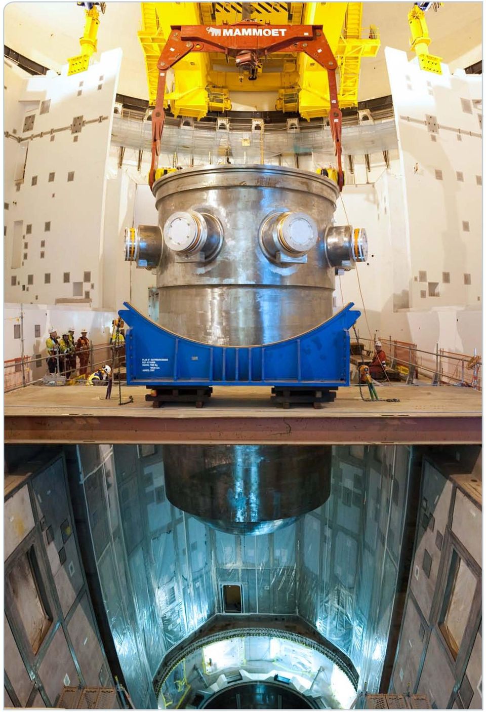
3 Contents TVO a pioneer in its own field Olkiluoto One unit, many buildings n PRIMARY CIRCUIT Reactor pressure vessel and internal structures Reactor core and fuel Reactor operation and control Primary coolant circuit n SECONDARY CIRCUIT Turbines and generator Condenser n SEA WATER COOLING SYSTEMS n NUCLEAR SAFETY n WATER CHEMISTRY AND VOLUME CONTROL SYSTEMS n INSTRUMENTATION AND CONTROL SYSTEMS n ELECTRICAL POWER SYSTEMS n WASTE PROCESSING SYSTEMS n TRAINING SIMULATOR Technical data The reactor pressure vessel was lifted into the reactor pit in June. Olkiluoto

4 Olkiluoto

5 TVO a pioneer in its own field Teollisuuden Voima Oyj (TVO) is a non-listed public company founded in to produce electricity for its stakeholders at cost price. TVO is the developer, owner and operator of the Olkiluoto nuclear power plant. The production of the nuclear power plant units in Olkiluoto (OL and OL) covers about one sixth of the total electricity consumption in Finland. Half of this electricity goes to the industry, the other half is consumed by private households, service sector and agriculture. Because of the need for increase in both self-sufficiency and additional capacity of electricity production, TVO is currently building a third power plant unit, Olkiluoto (OL). With the electrical output of approximately,00 MWe, OL will almost double the production capacity of the Olkiluoto power plant. In summer the Finnish Parliament granted TVO permission to build a fourth unit; Olkiluoto (OL). Solid nuclear expertise TVO employs a staff of about 00, many of them with solid experience in the operation and maintenance of a nuclear power plant gained over several decades. This expertise is also utilised and further developed in the construction of the OL and OL units. Throughout its existence, TVO has provided further training to the employees and improved the competence of the staff in nuclear technology. The company s nuclear expertise is being sustained by participating in international development programmes. Also the upgrading and modernisation projects as well as development and construction projects carried out at the existing Olkiluoto units develop the staff s expertise. The modernisation projects implemented over the years have improved the safety as well as the production capacity and economy of the Olkiluoto power plant. High in international ranking TVO s nuclear expertise is clearly evident by the high capacity factors of the Olkiluoto plant units. The capacity factors of OL and OL have varied between % and % since the early 0s, ranking among the very top by international comparison. The high capacity factors indicate reliability of operation, among other things. The results achieved are based on meticulous and proactive planning of annual outages and modifications. The radiation exposure doses of the personnel, which have been consistently low at the Olkiluoto power plant, have also yielded good results in international comparison. TVO s operating philosophy As a nuclear power company, TVO is committed to a high level safety culture, which creates the comprehensive basis for all activities. According to the principles of the safety culture, issues are prioritised according to their safety significance and a high degree of operability and reliability of production are the key objectives of operation. Safety and factors affecting safety always take priority over financial considerations. The future vision of TVO is to be an acknowledged Finnish nuclear power company and a pioneer in its field. To achieve this goal, TVO acts responsibly, proactively and transparently, following the principles of continuous improvement in close cooperation with various interest groups. Olkiluoto

6 Olkiluoto Olkiluoto (OL) was decided to build for many reasons. The added capacity brought by OL not only meets the increasing demand but also compensates for the decreasing output of ageing power plants. Together with the use of renewable energy, the unit helps Finland to reach its carbon dioxide emission targets, contributes to the stability and predictability of electricity prices and reduces Finland s dependence on imported electricity. It was on this basis that TVO submitted an application to the Government in November 00 concerning a Decision in Principle for the building of a new nuclear power plant unit. The Government adopted a Decision in Principle, and Parliament ratified the Decision in Principle on May 0. The Decision in Principle states that building the new nuclear power plant unit is in the interest of society as a whole. After a call for tenders, in December 0 TVO took the decision to invest in the construction of a power plant unit with a Pressurized Water Reactor (PWR) with an output of approximately,00 MWe at Olkiluoto. The type of the unit is known as a European Pressurized Water Reactor (EPR). The unit is being built on a turnkey basis by a consortium formed by AREVA NP and Siemens. AREVA NP is delivering the reactor plant, and Siemens is delivering the turbine plant. Experienced power plant suppliers Both of the principal suppliers are leaders in their respective fields. AREVA NP has delivered the principal components for a total of 0 light-water reactor units pressurized water reactors (PWR) and boiling water reactors (BWR). The most recently commissioned PWR units for which AREVA NP supplied the principal components are Civaux and in France, which went on stream in and, respectively. AREVA NP also delivered the principal components to units which went on stream in Brazil (Angra ) and China (Ling Ao and ) in 0. Siemens is one of the leading power plant suppliers in the world. The combined output of the power plants delivered by Siemens exceeds 00 GWe. Technology based on solid practical experience OL is an evolutionary unit compared with the current power plant units, meaning that its basic design is based on the proven technology of existing power plants. Its development was based on plants commissioned in France (N) and Germany (Konvoi). Safety features in particular have been developed further. The unit was originally designed to allow for the management of a severe reactor accident (cooling of core melt) and a large aircraft crash (double shell of the reactor containment building). Germany (Konvoi) Neckarwestheim, MWe Isar,00 MWe Emsland,0 MWe France (N) Chooz,0 MWe Chooz,0 MWe Civaux,0 MWe Civaux,0 MWe Olkiluoto

7 Operating principle of a pressurized water reactor (PWR) A PWR plant has two circuits for heat transfer. Water is kept under high pressure by the pressurizer () and circulated by the reactor coolant pumps () in the primary circuit (), which transfers the heat from the reactor () to the secondary circuit () in the steam generator (). Reactor power is controlled by control rods (). The pressure in the secondary circuit is much lower than in the primary circuit, which makes the water in the steam generator boil. The steam from the steam generator makes the turbine () rotate. The turbine rotates the coaxially mounted generator (), generating electricity for the national grid. The steam from the turbine is cooled back to water in the condenser () with sea water (). Condensate water is fed back to the steam generator with feedwater pumps (), and the warm sea water is pumped back into the sea. 0 years service life In addition to safety, the design of OL emphasizes economy in particular. The efficiency rate of the new unit, for instance, is % some four percentage points higher than the original efficiency of OL and OL. The design is based on an expected service life of 0 years for the largest structures and components and years for the more easily replaceable structures and components. Allowing in advance for such replacements enables the unit to have an economic service life of at least 0 years. Compared with similar units recently commissioned in Europe, OL will have a reactor output about % greater and an electricity output about % greater. OL is being delivered as a turn-key project. TVO has been responsible for site preparation and for the expansion of the infrastructure at Olkiluoto. Site preparation has involved earthmoving, excavation, road building, electrical power supply for the construction site and the building of the tunnels for the cooling water. The actual construction work that is the responsibility of the AREVA NP Siemens consortium began in 0. Multi-stage quality control and inspection are carried out by representatives of TVO, plant supplier, subcontractors, and authorities. Olkiluoto
 rotate.")
8 A Reactor building Inner and outer containment building Reactor building main crane (polar crane) Containment heat removal system: sprinklers Equipment hatch (large components) Refuelling machine Steam generator Main steam lines Main feedwater lines Reactor control rod drives Reactor pressure vessel Primary circuit reactor coolant pump Primary circuit main coolant lines C Safeguard building division Main control room Computer room Emergency feedwater tank D Safeguard building division Emergency feedwater pump Medium head safety injection pump E Safeguard building division Switchgear room Instrumentation & control room Battery rooms Emergency feedwater tank Component cooling system heat exchanger Low head safety injection pump Containment heat removal system heat exchanger (sea water circuit) Containment heat removal system heat exchanger F Fuel building Fuel building crane Refuelling machine Fuel pools Fuel transfer tube Fuel pool cooling system heat exchanger G Reactor plant auxiliary building 0 Coolant supply and storage system Coolant supply and storage system Offgas delayer Ventilation stack H Radioactive waste processing building Liquid waste collecting tank Monitoring tanks Primary circuit volume control system heat exchangers Core melt spreading area Emergency cooling water storage (In-containment refueling water storage tank, IRWST) Intake screens for the cooling system for reactor emergency cooling and containment heat removal system Hydraulic accumulator of the reactor emergency cooling system Primary circuit pressurizer Main steam valves Feedwater valves Main steam system safety valve and relief valve exhaust silencer B Safeguard building division >> >> >> Olkiluoto

9 Concentrate tanks Drum storage area I Emergency power generating building Emergency diesel generators J Access building K Office building L Turbine building Moisture separator/reheater 0 High-pressure feedwater preheaters High-pressure turbine Low-pressure turbine Condensers Cross over lines Generator Exciter Feedwater tank Turbine building main crane Low-pressure feedwater preheater 0 Feedwater pumps Low-pressure feedwater preheater M Switchgear building Transformer boxes N Circulating water pump building O Essential service water pump building P Anti-icing pumps Q Auxiliary boiler building Demineralized water storage tanks Auxiliary stand-by transformer Unit transformers Auxiliary normal transformers Switchyard High-voltage lines Computer graphics: Images & Process Olkiluoto building complexes AREVA NP (nuclear island) Siemens PG (turbine island) TVO (the office building) >> Olkiluoto

10 The reactor building is surrounded by the fuel building and four independent safeguard building divisions. Safeguard building division Fuel building Safeguard building division Reaktorirakennus Safeguard building division Polttoainerakennus Safeguard building division Reaktorilaitoksen poikkileikkaus CONTAINMENT BUILDING (REACTOR BUILDING) FUEL BUILDING SAFEGUARD BUILDING DIVISIONS AND SPENT FUEL MAST BRIDGE STORAGE AREA FOR RPV CLOSURE H. INCORE INSTRUMENT FUELSTORAGE POOL TRANSFERTATIONS STORAGE POOL SPRAY LINES SPRAY VALVES PIPE DUCT CVCS SG BLOW DOWN SYSTEM CVCS EBS TANK VALVE ROOM VALVE ROOM PIPE DUCT CVCS PUMP PIPE DUCT SPREADING AREA IRWST EBS PUMP SUMP Olkiluoto

11 One unit, many buildings The new OL power plant unit is being built to the west of the existing ones. The buildings in the new complex can be roughly divided into three parts: the nuclear island, the turbine island, and auxiliary and support buildings. Nuclear island The principal components of the nuclear island are the reactor containment, the fuel building and safeguard building divisions surrounding it. The reactor primary circuit is housed in a gas-tight and pressure-resistant double-shelled containment building, also known as the reactor building. The fuel building, which houses pools for fresh and spent fuel, is on the south side of the reactor building and is about 0 m long, about m wide and more than 0 m high. In addition to fuel storage, it is connected to workshop areas. Flanking the fuel building are the reactor plant auxiliary building and waste management building; the latter is used for handling plant waste. The reactor building, fuel building and safeguard building divisions are designed to be able to withstand various types of external hazards such as earthquakes and pressure waves caused by explosions. All these buildings are built on the same base slab. The reactor building, the fuel building and two of the safeguard building divisions are designed to withstand a crash by a large aircraft. Reactor containment building The OL reactor unit has a double-shelled containment building in reinforced concrete. The shape of the building was chosen for strength and on the basis of construction technology. The inner containment is a prestressed cylinder in reinforced concrete with an elliptical cover. It is designed to withstand temperature and pressure loads that may be caused by pipe breaks. The massive outer containment is a cylinder in reinforced concrete that shares the same base slab as the inner containment and protects it against external hazards. This massive double-shell structure is a new safety feature which the earlier power plants do not have. Preventing release of radioactive material in case of an accident sets extreme requirements on the leak-tightness of the containment building, which has an inner liner of steel for this reason. The tightness of the building is closely monitored. Any leaks which occur are arrested between the inner and outer shells of the containment building, then filtered and delayed in the annulus ventilation system before being conveyed to the ventilation stack. Personnel access to the containment building is managed through a special airlock during normal operation. The airlock has double-sealed doors at both ends; it is impossible to open both ends of the airlock at the same time. Personnel access is at ground level. There is also an emergency airlock on the service floor at about m level through which personnel access to and from the containment building can be managed. The big equipment hatch on the maintenance platform is used during construction and annual outages for bringing large components and devices into the containment building. The main crane of the reactor building, located above the containment building service floor has a lifting capacity of tonnes. The reactor building has an external diameter of about m, a volume of about 0,000 m and a total height including underground levels of about 0 m. The ventilation stack is about 0 m high. Olkiluoto

12 The inner containment building is clad with steel to ensure the gas-tightness of the building. The containment s design pressure is. bar. Lifting of the steel liner dome part in November 0. Olkiluoto

13 Safeguard buildings The OL plant unit has parallel redundant safety systems which are physically separated from each other to ensure safe operation under all circumstances. The safety systems are divided into four independent subsystems, each of which is housed in a separate safeguard building division. All four buildings have their own low head and medium head safety injection systems, a residual heat removal system, an intermediate cooling system, a sea water cooling system, and an emergency feedwater system. The electrical and instrumentation and control systems are located on the upper levels of the safeguard building divisions. The control room is located in one of the safeguard building divisions. Buildings and are between the reactor building and the turbine island, and buildings and are on opposite flanks of the reactor building. Each of the buildings is about m long, m wide and m high. The power plant unit has four emergency diesel generators suppling power to the safety systems in case of loss of offsite power. There are also two additional diesel generators, station blackout diesels, independent of the above four. The emergency and station blackout diesel generators ensure that the safety systems have power supply even under abnormal circumstances. Turbine island The turbine building is almost 0 m long, 0 m wide and 0 m high, including underground levels. Its volume is about 0,000 m. Adjacent to it are the circulating water pump building and switchgear building. The main transformers and plant transformers are located to the north of the turbine building. Auxiliary and support buildings Beside safeguard building divisions and, there is an access building, which contains locker rooms and washrooms, and a monitored accessway to the radiation-controlled area. There is a bridge from the access building to the office building, where radiation-controlled office space is available during annual outages. The power plant area also contains separate buildings for housing diesel generators, the sea water system buildings (mainly underground), and a number of minor support buildings. September Olkiluoto

14 Primary circuit main components Reactor pressure vessel Main coolant line, hot leg Steam generator Main coolant line, cross-over leg Reactor coolant pump Main coolant line, cold leg Pressurizer Pressurizer surgeline Olkiluoto

15 PRIMARY CIRCUIT Primary circuit The OL primary circuit system consists of four individual loops. It is designed for a service life of 0 years and constructed to withstand the loads caused by every conceivable situation of operation or accident. Primary circuit main functions In each of the four loops comprising the primary circuit, the coolant leaving the reactor pressure vessel at a temperature of C goes through the main coolant line hot legs to the steam generators, where heat is transferred to the secondary circuit. The coolant, its temperature now approximately C, is returned by the reactor coolant pump to the reactor through the inlet nozzles. Inside the reactor pressure vessel, the coolant first flows down outside the reactor core. From the bottom of the pressure vessel, the flow is reversed up through the core, where the coolant temperature increases as it passes through the fuel rods and the assemblies formed by them. The pressurizer connected to the primary circuit keeps the pressure in the reactor high enough to prevent the coolant from boiling. Under normal conditions, the circuit is full of water which effectively transfer heat from the reactor core. Connected to one of the four individual loops, the pressurizer is larger in volume compared with the existing power plants so that it can better respond to any pressure transients during operation. This helps smooth pressure spikes and extends the useful life of the main components of the primary circuit. The safety systems are designed so that in abnormal events they are able to perform a rapid shut-down of the reactor, known as a reactor scram. This ensures that the reactor releases as little energy as possible while also helping reduce pressure with maximum efficiency and keeping the actuation of the safety valves to a minimum. Aligning of a cross-over leg. Reactor cooling system properties Reactor thermal power,0 MWth Primary circuit flow, kg/s Primary coolant flow per loop, m /h Coolant temperature in the cold leg C Coolant temperature in the hot leg C Primary circuit design pressure bar Primary circuit operating pressure bar Secondary circuit design pressure 0 bar Main steam pressure under normal conditions bar Main steam pressure during hot shut-down 0 bar Olkiluoto

16 Properties of the reactor pressure vessel and its PWR inner structures Reactor pressure vessel Design pressure Control Rod Drive Mechanis bar m(crdm) Design temperature C Life time (capacity factor 0%) 0 years Inside diameter (under cladding), mm Wall thickness (under cladding) 0 mm Bottom wall thickness mm Height with closure head,0 mm Base material MND Cladding material stainless steel (less than 0.0% cobalt) Mass with closure head t End of life fluence level (E > MeV) - design value. x n/cm - expected value ca. x n/cm Base material final RT NDT (final ductile-brittle transition temperature) ca. C Closure head Wall thickness 0 mm Number of penetrations: - control rod mechanisms pcs - dome temperature measurement pcs - instrumentation pcs - coolant level measurement pcs Base material MND * Cladding material stainless steel (less than 0.0% cobalt) Upper inner structures Upper support plate thickness 0 mm Upper core plate thickness 0 mm Main material Z CN - / Z CN -** Lower inner structures Lower support plate thickness mm Lower inner structure material Z CN - / Z CN -** Neutron reflector Material Z CN -** Weight 0 t * low-alloy ferrite steel ** austenitic stainless steel Cross-section of reactor pressure vessel and internal structures Control rod drive mechanism Reactor pressure vessel head Control rod guide assembly Core barrel Coolant inlet nozzle Pressure vessel shell Core support grid Flow distribution plate Reactor level measurement probe Coolant outlet nozzle Control assembly Fuel assembly Olkiluoto
 ca.")
17 Reactor pressure vessel and internal structures Primary circuit Pressure vessel The reactor pressure vessel contains the reactor core. Both the pressure vessel and the vessel head are made of forged ferrite steel. They are also clad with stainless steel on the inside to prevent corrosion. The pressure vessel is supported by beams which rest on the support ring in the top part of the reactor cavity, under the eight primary circuit pipes. The vessel head is fastened with bolts and a sealing gasket. To manufacture the reactor with as few welding seams as possible, the flange and nozzle area of the pressure vessel is forged from a single piece of metal. There are no welding seams between the flange and the nozzles. Combined with the structure of the nozzles, this ensures that there is a considerable distance and a large volume of water between the nozzles and the top of the core. This minimizes the exposure of the structures to neutron radiation. Internal structures The internal structures of the reactor pressure vessel support the fuel assemblies in the core, enabling the reactivity of the core to be controlled by the control rods and the fuel to be cooled with water under all circumstances. The inner structures are partly removed during refuelling and can be completely removed for an inspection of the inner wall of the pressure vessel. The pressure vessel also contains upper internal structures, whose function is to support the top of the fuel assemblies and to keep them correctly aligned axially. These Source: AREVA Reactor pressure vessel upper inner structures (Chooz, France). structures include the control rod guide thimbles, whose fastenings and beams are fixed to the control rod support plate and the upper core support plate. Core barrel The flange of the core barrel rests on the machined flange of the pressure vessel, and is kept in place by a large spring. The fuel assemblies rest on a perforated core support plate, made of forged stainless steel and welded to the core barrel. Each fuel assembly is positioned by two pins 0 apart. Neutron reflector (heavy reflector) There is a steel neutron reflector, heavy reflector, around the polygonal core, between the core and the cylindrical core barrel. The reflector reduces the number of neutrons escaping from the core and flattens the power distribution. It also reduces the exposure of the pressure vessel to the neutron radiation that reduces ductility in its material, and also dampens any pressure spikes which the internal structures and fuel in the reactor might be exposed to in case of pipe break. The heavy reflector consists of pieces of stainless steel piled up and linked together. The tie rods bolted to the core support plate keep the pieces in place axially. The heat generated in the steel by gamma radiation is absorbed by the primary coolant flowing through cooling ducts in the reflector. Olkiluoto

18 Initial core loading In-core instrumentation TC Low enriched assembly without gadolinium Medium enriched assembly with gadolinium High enriched assembly with gadolinium Aeroball system (neutron flux measurement calibration system) Core instrumentation Reactor core properties Reactor thermal power,0 MWth Operating pressure bar Primary coolant temperature in the inlet C Primary coolant temperature in the outlet C Equivalent diameter, mm Active core height,0 mm Number of fuel assemblies pcs Number of fuel rods, pcs Average linear heat rate. W/cm lance yokes, each comprising: core outlet temperature sensors in-core neutron flux detectors - aeroball probes control assemblies water level probes core external neutron flux measurements TC temperature measurement Olkiluoto

19 Reactor core and fuel Primary circuit The OL reactor core consists of fuel assemblies identical in structure. For the initial core loading, the assemblies are divided into three groups according to their enrichment level. The two groups with the highest levels of U also contain gadolinium, which acts as a neutron absorber and thus reduces the reactivity of the initial phase of the reactor s operation and flattens the power distribution. The number and properties of the fuel assemblies replaced annually depend on the fuel management plan chosen, particularly the load pattern and the length of the refuelling interval. The refuelling interval of the reactor core can be to months. The primary coolant, due to its composition, is a significant neutron moderator and reflector. The coolant conveys heat from the core at a pressure of approximately bar and a temperature of C on average. The primary coolant contains boron, which absorbs some of the neutrons. Adjusting the boron level helps control changes in reactivity that are fairly slow, such as the impact of fuel burn-up. Rapid changes in reactivity and in power Ball guide tube Carrier gas Shroud Steel balls Ball stop Active core height Aeroball system Balls made of a vanadium alloy are fed into 0 narrow tubes from above the reactor and pneumatically propelled to the reactor core through guide tubes in the fuel assemblies. The activation of the balls in one tube is measured at points. The results are used to calibrate the devices used to measure the neutron flux in the reactor core. output are controlled using the control assemblies. The main core properties and operational conditions have been selected to achieve a high thermal power and low fuel costs. The OL reactor core is also designed to be adaptable to various refuelling intervals and operating situations. Core instrumentation The core power is measured with both internal and external instrumentation. The fixed in-core instrumentation comprises neutron flux and temperature measurements monitoring the distribution of the neutron flux in the core and the temperature distribution in the upper part of the core. Ex-core instrumentation is used for power measurement and also for monitoring core sub-criticality during outages. All the penetrations required for core instrumentation are in the pressure vessel head. The core power distribution is also measured at regular intervals using the aeroball system. The results thus achieved are used for calibrating fixed in-core neutron flux measurement devices. Olkiluoto

20 x fuel assembly Top nozzle Spacer grid Fuel rod Fuel properties Fuel uranium dioxide UO Fuel assembly type x HTP Number of fuel rods per assembly pcs Number of guide thimbles per assembly pcs Number of spacer grids per assembly pcs Length of fuel assembly. m Weight of fuel assembly kg Width of fuel assembly. mm Cladding material M TM UO pellet density. g/cm Fuel discharge burnup MWd/kgU Bottom nozzle Olkiluoto

21 Primary circuit Fuel assembly A fuel assembly consists of fuel rods, spacer grids and top and bottom nozzles. The guide thimbles, spacer grids and the end pieces form the supporting structure of the assembly. The fuel rods form a x matrix. Each fuel assembly contains fuel rods, guide thimbles and spacer grids, tied together by end pieces at either end. The bottom nozzle is shaped to distribute coolant flow evently. There is also The fuel supplier for the a debris filter at the lower end to prevent OL reactor is AREVA NP. any foreign objects that may end up in the primary circuit from entering the fuel assembly; such objects could mechanically damage it. The top nozzle has a leaf spring set on each side to achieve the force with which the fuel assemblies are kept stationary against the primary coolant flow. The eight middle spacer grids in the fuel assembly are made of zirconium alloy. They have flow guides to enhance heat transfer from the fuel rods. The uppermost and lowermost spacer grids are made of nickel-based alloy because of their higher strength requirements. Source: AREVA Fuel rods A fuel rod is a tube containing compressed ceramic pellets of uranium dioxide (UO ). The rods are welded hermetically leaktight and pressurized using helium. The power of the reactor comes from the fission of the uranium in the pellets, mainly the isotope U. The enrichment level of the pellets varies, being just under % at its highest. In some of the fuel rods, the fuel pellets are made of an alloy of UO and Gd O, the latter helping to reduce reactivity and to flatten the power distribution in fresh fuel rods. The cladding tubes of the fuel rods are made of a zirconium alloy. The cladding is the first barrier to the release of radioactive emissions as it separates the fuel and their fissile products from the primary coolant. There is space for fission gases within the fuel rod, which reduces the pressure increase caused by gases released from the uranium pellets in the nuclear reaction. The pellets are held in place by a spring inside the top of the fuel rod. Olkiluoto
22 Primary circuit Fuel handling Fresh fuel assemblies are stored either in the fresh fuel dry storage or in storage racks in the fuel pools where spent assemblies are also stored. During a refuelling outage, some of the spent fuel assemblies in the reactor are replaced with fresh ones. For example, if the reactor is being operated at -month cycles, one quarter of fuel is replaced annually. Different kinds of fuel assemblies are placed in the reactor in compliance with the restrictions on the reactor core and fuel use. Fuel assemblies are moved between the reactor and the fuel building through the fuel transfer tube. There is a fuel handling machine in the reactor building and in the fuel building. Core unloading takes about 0 hours in all, and core reloading plus a final core inspection using the camera in the refuelling machine takes about hours. The final inspection is intended to ensure the correct placement of fuel assemblies in the core, following the refuelling plan. The Finnish Radiation and Nuclear Safety Authority (STUK), Euratom and the IAEA all participate in each final inspection to ensure the appropriate handling and safeguard measures of reactor fuel. Spent fuel assemblies that have been in the reactor are kept under water at all times for cooling and radiation protection. Although m of water would be sufficient radiation protection, at Olkiluoto the fuel assemblies are always kept under at least m of water. Spent fuel assembly handling After being removed from the reactor, spent fuel assemblies are kept in the spent fuel pools in the fuel building for a few years to cool them off. At the same time, the radioactivity of the spent fuel decreases substantially. After sufficient cooling, the spent fuel is transported to an interim storage facility at the power plant site using a spent fuel cask which is docked below the spent fuel pool using a transfer facility. Before placement in the final repository, the spent fuel is kept in interim storage for several decades. During this time, the radioactivity and heat output of the fuel decrease to less than /00 of their original values, making the further handling of the fuel much simpler. The final repository for spent fuel is being built at Olkiluoto by Posiva Oy, a company which is jointly owned by TVO and Fortum Power and Heat Oy, who will also be responsible for its operation. The spent fuel from the nuclear power plant units in Loviisa will also be deposited at Olkiluoto. Final placement will begin in. Olkiluoto
23 Primary circuit Transferring fuel out of and into the core The refuelling machine lifts a fuel assembly out of the reactor core and transfers it to the transfer container, which is in a vertical position. The transfer mechanism turns the transfer container to a horizontal position and moves it from the reactor building through the transfer tube to the fuel building. The container is again turned to a vertical position, and the spent fuel mast bridge lifts the fuel assembly out and transfers it to the spent fuel storage rack in the spent fuel pool. Installing new fuel assemblies in the core is performed using the same process in reverse. Fuel transfer systems in the reactor building and fuel building Spent fuel mast bridge in the fuel building Refuelling machine in the reactor building Fuel transfer tube Fuel assembly transfer mechanism Olkiluoto
24 Cross-section of control rod drive mechanism Plug connector Control rod system properties Rod cluster control assemblies Number pcs Weight. kg Control rods per assembly Absorber BC part (upper part) - natural boron.% B atoms - specific weight. g/cm - external diameter. mm - length,0 mm AIC part (lower part) - weight composition: silver, indium, cadmium (%) 0,, - specific weight. g/cm - external diameter. mm - length,00 mm Cladding Material stainless steel Surface treatment (external surface) ion nitrification External diameter. mm Internal diameter. mm Filling gas helium Control rod drive mechanisms Number of drive mechanisms pcs Weight 0 kg Lifting power >,000 N Travel range,0 mm Stepping speed mm/min or 0 mm/min Maximum scram time allowed. sec Materials austenitic and martensitic stainless steel Upper limit position indicator coil Position indicator coil Lower limit position indicator coil Lifting pole Lift armature Gripping armature Gripping latch Gripping latch carrier Holding pole Holding latch carrier Holding armature Holding latch Flange connection Sealing area Drive rod upper final position Lifting coil Gripping coil Holding coil Sheet steel casing Drive rod lower final position Control rod drive mechanism nozzle Olkiluoto
25 Reactor operation and control Primary circuit The control assemblies are one system to control the reactor power. In addition to short-term power control, they also flatten vertical power distribution in the reactor core. In the long term, decreasing the boron content helps compensate for the loss of reactivity due to fuel burnup. Control rod system The control rod system is a part of the reactor power control system. It consists of Source: AREVA the control assemblies formed with control rods, the control rod drive mecha- reactor control assemblies move in The individual control rods of the nisms and the control rod drive mechanism operating system. The system is used blies. These guide thimbles are also the guide thimbles in the fuel assem- for controlling the reactor power and for a used for placing instrumentation and reactor scram. The control rods enter the neutron sources. core through guide thimbles in the fuel assemblies. Control rod drive mechanisms The control rod system is governed by the reactor control, surveillance and limitation system and manually by the control room operators. The reactor scram is triggered automatically by the protection system or its backup system, a hardwired back-up system. An operator may also trigger the reactor scram manually. Control assemblies There are identical control assemblies. Each consists of identical absorber rods attached to a single mount. The rods contain materials that absorb neutrons (silver, indium, cadmium and boron carbide). When the rods are completely inserted into the core, they almost totally cover the active length of the fuel assemblies. The control assemblies are divided into separate control groups. The majority of them, elements, are in the shut-down bank, which executes a rapid shut-down of the reactor, or reactor scram, if necessary. The remaining elements control the temperature of the primary circuit and flatten vertical power distribution in the reactor core. The control assemblies in the control bank are further divided into quadruplets, which are used in various drive sequences and insertion sequences depending on the refuelling interval in progress. The current insertion sequence and control assembly banks can be changed at any time regardless of the current reactor power. The control bank in operation is regularly changed at intervals of about days of power operation. This avoids fuel discharge burnup from affecting the effectiveness of the control and equalizes the burnup. A control rod drive mechanism consists of the pressure housing with flange connection, the latch unit, the drive rod, the coils and their housings. The role of the control rod drive mechanisms in controlling the reactor is to move the control assemblies throughout the length of the core and to keep them at any location required. Their secondary role is to drop the control assemblies into the reactor, thus stopping the chain reaction and shutting the reactor down in a number of seconds, particularly in a scram situation. When the reactor scram signal is activated, all operating coils are de-energized, the latches are retracted from the rod grooves, and the control assemblies drop into the core by force of gravity. The control rod drive mechanisms are installed into adapters welded to the reactor pressure vessel head. Each drive mechanism is a separate entity that can be installed and removed independently of the others. Olkiluoto
26 Cross-section of steam generator Steam outlet nozzle Secondary manway Steam dryer Steam generator properties Number of steam generators pcs Heat transfer surface per steam generator,0 m Primary circuit design pressure bar Primary circuit design temperature C Secondary circuit design pressure 0 bar Secondary circuit design temperature C Heat transfer tube external diameter / wall thickness.0 mm /.0 mm Number of tubes,0 pcs Triangular pitch. mm Total height m Materials Tubes Inconel 0 alloy, heat treated Shell MND * Cladding tube sheet Ni-Cr-Fe alloy Tube support plates % Cr-treated stainless steel Other Total weight t Feedwater temperature 0 C Main steam moisture content 0.% Main steam flow, kg/s Main steam temperature C Main steam saturated pressure bar Pressure during hot shut-down 0 bar *low-alloy ferrite steel Emergency feedwater nozzle Upper lateral support brackets Bundle wrapper Tube sheet Partition plate (primary circuit) Coolant inlet nozzle Steam separator Emergency feedwater ring Feedwater ring Feedwater nozzle Bundle double wrapper Tube support plates Partition plate Tube bundle Coolant outlet nozzle Olkiluoto
27 Primary coolant circuit Primary circuit Steam generators A steam generator is a heat exchanger which transfers heat from the primary coolant circuit to the water in the secondary circuit. As in a typical heat exchanger, the contents of the primary and secondary circuits never come into direct contact with one another. The steam generator in an EPR power plant unit is of the vertical type. The primary coolant passes through U-shaped tubes in the steam generator. The feedwater of the secondary circuit, which is to be turned into steam, circulates inside the shell of the steam generator. The steam separators and steam dryer at the top of the secondary circuit portion separate the steam from the water. The separated water returns down along the outer shell of the steam generator. The feedwater pipes continously refill the secondary side of the steam generator with water equivalent to the mass of steam fed into the turbine. The axial feedwater preheater enables not only a larger heat exchange area but also a saturation pressure of bar, which is a significant factor in the high efficiency (%) of the power plant unit. The tubes in the steam generator are made of wear-resistant and corrosion-resistant alloy called Inconel 0, which has a cobalt content of less than 0.0%. The shell of the steam generator is made of MND steel. The design concept, with the cold feedwater being mixed with only % of the warmer recirculated water, ensures a larger temperature differential and hence a more efficient heat transfer. As a result, the main steam pressure of the OL steam generator is bar higher per unit of heat exchange area than that of power plant units which the design is based on. The efficiency of the steam generator is achieved through the asymmetrical conveying of feedwater into a discrete channel separated from the walls of the steam generator. In the design of the OL steam generators, particular attention was paid to the prevention of cross-flows in the secondary circuit and of the adverse effects caused by thermal layering due to the efficient heat exchange. The steam space has been enlarged, increasing the steam volume. On the other hand, the steam generator also has a higher water volume than in the power plant units upon which the design is based. This improves the safety margin and increases the grace period in a situation where all feedwater systems malfunction and no cooling water is available for feeding into the steam generator. Olkiluoto
28 Cross-section of reactor coolant pump Reactor coolant pump and pipe properties Pump casing Pump Number of pumps pcs Design pressure bar Design temperature C Primary coolant flow, m /h Design head 0. m ± % Seal water injection. m /h Seal water return 0.0 m /h Speed, rpm Total height. m Total weight without water and oil t Motor Rated power,000 kw Frequency 0 Hz Main circulation pipes Internal diameter 0 mm Wall thickness mm Material Z CN -* Pressurizer connection pipe Internal diameter. mm Thickness 0. mm Material Z CN -* *low carbon stainless austenitic steel. Flywheel. Radial bearings. Thrust bearing. Air cooler. Oil cooler. Motor (stator). Motor (rotor). Motor shaft. Spool piece. Pump shaft. Shaft seal housings. Main flange. Seal water injection. Thermal barrier. Diffuser. Impeller. Pump casing. Outlet nozzle. Inlet nozzle Olkiluoto
29 Primary circuit Reactor coolant pump The reactor coolant pumps provide forced circulation of water through the reactor coolant system. This circulation removes heat from the reactor core to the steam generators, where it is transferred to the secondary circuit. In each of the four loops of the primary circuit, the reactor coolant pump is located between the steam generator outlet and the reactor inlet. The reactor coolant pumps have hydrostatic bearings, which ensure a low vibration level. The OL reactor coolant pumps at the Jeumont plant in France Reactor coolant pump have three separate shaft seals and an additional standstill seal which is operated (N,,00 MWe). by gas pressure. A reactor coolant pump consists of three main parts: the pump itself, the shaft seals and the motor. The pump hydraulic cell consists of the impeller, the diffuser and the suction adapter. The pump shaft is in two parts connected by a spool piece which can be removed for seal maintenance. The shaft is supported on three bearings: two oil-lubricated bearings in the motor and one hydrostatic bearing at the impeller. There is a doubleaction thrust bearing at the top of the motor shaft, under the flywheel, to compensate axial forces. Source: AREVA The shaft seal system consists of three dynamic seals assembled into a cartridge and a standstill seal. The first seal is a hydrostatically controlled leakage seal, which takes the full primary pressure. The second seal is a hydrodynamic seal which receives the remaining pressure but can also withstand the entire primary pressure if necessary. The third seal is also hydrodynamic and is a backup leak seal. The standstill seal ensures that no primary coolant is lost in the event of a loss of power or the simultaneous malfunction of all shaft seals when the pump is stopped. When the pump is in operation, the shaft seals are cooled and lubricated with seal injection water which is injected below the seals at a pressure slightly higher than that of the primary coolant. The third shaft seal, which is a backup to the first two, receives its cooling water from the demineralized water distribution system. The motor is a drip-proof squirrel-cage asyncronous motor. A spool piece placed between the pump and the motor shafts and the shaft seal housing structure enable maintenance to be carried out on the seal pack without removing the motor. Olkiluoto
30 Cross-section of pressurizer Venting nozzle Access hatch Safety valve nozzle Level and temperature measurement nozzle Convex end Source: AREVA Spray inlet Spray nozzle Cylinder shells Pressurizer properties Design pressure bar Design temperature C Total volume m Total length. m Base material MND * Cylindrical shell thickness 0 mm Number of heaters Total weight, empty 0 t Total weight, filled with water t Number of safety valves and capacity under design pressure x 0 t/h Relief valve capacity under design pressure (doubled for valves) x 00 t/h * low-alloy ferrite steel Support plate Level and temperature measurement nozzle Heaters Support Convex end Flow distributor Surge line Olkiluoto
31 Primary circuit Pressurizer The pressurizer contains primary coolant in its lower part and steam in its upper part. The pressurizer is part of the primary circuit and is connected through a surge line to the hot leg of one primary loop. The purpose of the pressurizer is to keep the pressure in the primary circuit within specified limits. The pressure in the primary circuit is controlled by regulating the steam pressure. For this purpose, the pressurizer has heaters in its lower part to produce steam and a spray system in its upper part to condense steam into water. The pressure-relief and safety valves at the top of the pressurizer protect the primary circuit against excessive pressure. There are two parallel pressure-relief lines with valves which the operators can use, in the case of a severe accident, to relieve pressure quickly in the primary circuit: the primary coolant released from the primary circuit is discharged to the pressurizer relief tank, where a rupture disk breaks and releases the coolant into the containment building. There the steam condenses into water, which is collected in the emergency cooling water storage tank at the bottom of the containment building and pumped back into the reactor. The maintenance platform running around the pressurizer facilitates heater replacement and reduces radiation doses during valve maintenance. All components of the pressurizer shell, except for the heater penetrations, are made of forged ferrite steel with two layers of cladding. The material is the same as in the reactor pressure vessel. The heater penetrations are made of stainless steel and are welded using a corrosion-resistant alloy. The pressurizer supports are welded to its frame. Compared with plants which the design of OL is based on, the volume of the pressurizer has been increased in order to smooth the response to operational transients. Main coolant lines The main coolant lines of the four loops that form the primary circuit and the pressurizer surge line are part of the reactor coolant system in the reactor building. The main coolant lines convey the primary coolant from the reactor pressure vessel to the steam generators and onward to the reactor coolant pumps, which return the coolant to the pressure vessel. One of the four loops is connected to the pressurizer. Each of the four loops has three parts: the hot leg from the reactor pressure vessel to the steam generator, the cross-over leg from the steam generator to the reactor coolant pump, and the cold leg from the reactor coolant pump to the reactor pressure vessel. The main circulation pipes are made of forged austenitic stainless steel, which is resistant to thermal fatigue and can be inspected using ultrasound. The pressurizer was installed in November. Olkiluoto
32 Moisture separator reheater (MSR) High-pressure turbine Low-pressure turbine Condenser Generator Olkiluoto
33 SECONDARY CIRCUIT The purpose of the steam-water secondary circuit in the turbine plant is to convert the thermal energy of the main steam entering from the nuclear island into electrical energy through the turbine and generator as efficiently as possible and to return the secondary-circuit feedwater to the steam generators in the reactor plant. There is no radioactivity in the secondary circuit because the water of the primary and secondary circuits are separated from each other. Secondary circuit Main steam system The main steam generated in the steam generators belonging to the primary circuit is fed to the turbine plant through the four main steam lines. The main steam is fed to the high-pressure (HP) turbine through the high pressure turbine stop and control valves located in each main steam line. Every main steam line has a relief train, safety valves and an isolation valve in the event of abnormal operation. The steam is conveyed through the relief system and the safety valves straight into the atmosphere. The exhaust steam from the HP turbine is dried and reheated in the moisture separator reheaters (MSR). The reheating is performed in two stages, using extracted steam from the HP turbine extraction A and from the main steam extracted between the HP turbine stop and control valves. From the MSRs, the reheater steam goes through the LP turbine stop and control valves to the three LP turbines. The exhaust steam from the LP turbines is condensed in three separate sea water condenser units. In addition to condensing the steam from the LP turbines, the turbine bypass steam is also condensed in these condenser units. The purpose of the turbine bypass steam system is to control the main steam pressure depending on the power plant operation mode. Main condenser and condensate system There are three condensate extraction pumps (CEP), two pumping the main condensate from the condenser condensate chambers (hot wells) to the feedwater storage tank through the low-pressure feedwater preheating system. The third pump acts as a stand-by pump. The main condensate is preheated in four low-pressure feedwater heating stages to improve the efficiency of the steam-water process. The main condensate system also contains a mechanical condensate purification system for removing impurities. Feedwater system There are four feedwater pumps, three pumping feedwater from the feedwater storage tank through the high pressure feedwater preheating system to the steam generators. The fourth pump acts as a stand-by pump. The feedwater is preheated in three feedwater heating stages in two trains, each train consisting of two high-pressure feedwater preheaters and the reheating stage condensate coolers. The steam is extracted into the high-pressure feedwater preheaters from the HP turbine extractions A and A. From the preheating system, the feedwater is conveyed through the feedwater valves in the safeguard building divisions into the steam generators. Olkiluoto
Boiling Water Reactor Systems
 Boiling Water (BWR) s This chapter will discuss the purposes of some of the major systems and components associated with a boiling water reactor (BWR) in the generation of electrical power. USNRC Technical
Olkiluoto 3 Basic Facts
 Olkiluoto 3 Basic Facts TVO a world-class nuclear power company Teollisuuden Voima Oy (TVO) is a Finnish limited liability company established in 1969. The operating idea of the Company is to produce electricity
Physics and Engineering of the EPR
 Physics and Engineering of the EPR Keith Ardron UK Licensing Manager, UK Presentation to IOP Nuclear Industry Group Birchwood Park, Warrington UK, November 10 2010 EPRs in UK EPR is Generation 3+ PWR design
How To Clean Up A Reactor Water Cleanup
 General Electric Systems Technology Manual Chapter 2.8 Reactor Water Cleanup System TABLE OF CONTENTS 2.8 REACTOR CLEANUP SYSTEM... 1 2.8.1 Introduction... 2 2.8.2 System Description... 2 2.8.3 Component
BWR Description Jacopo Buongiorno Associate Professor of Nuclear Science and Engineering
 BWR Description Jacopo Buongiorno Associate Professor of Nuclear Science and Engineering 22.06: Engineering of Nuclear Systems 1 Boiling Water Reactor (BWR) Public domain image by US NRC. 2 The BWR is
V K Raina. Reactor Group, BARC
 Critical facility for AHWR and PHWRs V K Raina Reactor Group, BARC India has large reserves of Thorium Critical facility Utilisation of Thorium for power production is a thrust area of the Indian Nuclear
Olkiluoto 3 Project June 2010
 Olkiluoto 3 Project June 2010 Author: R&S Communications Department, La Défense, France. The reproduction, transmission or use of this document or its contents is not permitted without express written
Pressurized Water Reactor Systems
 Pressurized Water Reactor (PWR) Systems For a nuclear power plant to perform the function of generating electricity, many different systems must perform their functions. These functions may range from
HOW DOES A NUCLEAR POWER PLANT WORK?
 HOW DOES A NUCLEAR POWER PLANT WORK? O n t a r i o P o w e r G e n e r a t i o n P U T T I N G O U R E N E R G Y T O U S G O O D E O N T A R I O P O W E R G E N E R A T I O N What a Nuclear Reactor Does
NUCLEAR POWER PLANT SYSTEMS and OPERATION
 Revision 4 July 2005 NUCLEAR POWER PLANT SYSTEMS and OPERATION Reference Text Professor and Dean School of Energy Systems and Nuclear Science University of Ontario Institute of Technology Oshawa, Ontario
Swiss media visit to Olkiluoto August 15, 2014
 Swiss media visit to Olkiluoto August 15, 2014 Käthe Sarparanta Senior Adviser, Project Department Teollisuuden Voima Oyj NUCLEAR POWER PLANTS IN FINLAND Olkiluoto, Eurajoki Population 5.4 million Power
Nuclear power plant systems, structures and components and their safety classification. 1 General 3. 2 Safety classes 3. 3 Classification criteria 3
 GUIDE 26 June 2000 YVL 2.1 Nuclear power plant systems, structures and components and their safety classification 1 General 3 2 Safety classes 3 3 Classification criteria 3 4 Assigning systems to safety
Nuclear Design Practices and the Case of Loviisa 3
 Nuclear Design Practices and the Case of Loviisa 3 Harri Tuomisto Fortum Power, Finland Third Nuclear Power School, 20-22 October 2010, Gdańsk, Poland 22 October 2010 Harri Tuomisto 1 Objectives The objective
C. starting positive displacement pumps with the discharge valve closed.
 KNOWLEDGE: K1.04 [3.4/3.6] P78 The possibility of water hammer in a liquid system is minimized by... A. maintaining temperature above the saturation temperature. B. starting centrifugal pumps with the
Public SUMMARY OF EU STRESS TEST FOR LOVIISA NUCLEAR POWER PLANT
 1 (8) SUMMARY OF EU STRESS TEST FOR LOVIISA NUCLEAR POWER PLANT 1 LOVIISA NUCLEAR POWER PLANT Loviisa town is located approximately 90 km eastwards from Helsinki at the coast of Gulf of Finland. Loviisa
AREVA, an unparalleled experience in building nuclear reactors
 AREVA, an unparalleled experience in building nuclear reactors Frank APEL Senior Vice President Sales Central Europe and Nordic Countries AREVA, International Commercial Organisation 9 th Annual European
FUNDAMENTAL SAFETY OVERVIEW VOLUME 2: DESIGN AND SAFETY CHAPTER G: INSTRUMENTATION AND CONTROL
 SUB-CHAPTER: G.5 PAGE : 1 / 37 SUB CHAPTER G.5 INSTRUMENTATION 0. SAFETY REQUIREMENTS 0.1. SAFETY FUNCTIONS The instrumentation is directly involved in the three fundamental safety functions: Reactivity
10 Nuclear Power Reactors Figure 10.1
 10 Nuclear Power Reactors Figure 10.1 89 10.1 What is a Nuclear Power Station? The purpose of a power station is to generate electricity safely reliably and economically. Figure 10.1 is the schematic of
Teollisuuden Voima Oyj - General Presentation January 2009. Ilkka Mikkola Senior Adviser (Former Fuel Manager) Teollisuuden Voima Oyj
 Teollisuuden Voima Oyj") Teollisuuden Voima Oyj - General Presentation January 2009 Ilkka Mikkola Senior Adviser (Former Fuel Manager) Teollisuuden Voima Oyj Nuclear Power Plants in Finland in 2008 Olkiluoto OL1 BWR 860 MW 1978
Teollisuuden Voima Oyj - General Presentation January 2009 Ilkka Mikkola Senior Adviser (Former Fuel Manager) Teollisuuden Voima Oyj Nuclear Power Plants in Finland in 2008 Olkiluoto OL1 BWR 860 MW 1978
Current state of plant Functioning as a peak and emergency centre. Statistics Accumulated operating hours:
 Current state of plant Functioning as a peak and emergency centre Statistics Accumulated operating hours: D1-2-3-6-7: 43000 to 48000 hrs D4-5: 53000 to 57000 hrs D8: 33000 hrs Layout of the plant Index:
Government Degree on the Safety of Nuclear Power Plants 717/2013
 Translation from Finnish. Legally binding only in Finnish and Swedish. Ministry of Employment and the Economy, Finland Government Degree on the Safety of Nuclear Power Plants 717/2013 Chapter 1 Scope and
NUCLEAR POWER OVERALL GOOD FOR THE SOCIETY Finnish German Energy Day, 7th November 2012
 NUCLEAR POWER OVERALL GOOD FOR THE SOCIETY Finnish German Energy Day, 7th November 2012 Tanhua Jarmo Teollisuuden Voima Oyj 2 EU ENERGY ROADMAP 2050 NUCLEAR POWER IN ALL SCENARIOS Consumption of electricity
The EPR reactor the reference for New Build
 The EPR reactor the reference for New Build The reference for New Build The Reference for Safety The EPR design offers the highest level of safety: Already licensed in France, Finland and China Strong
7.1 General 5 7.2 Events resulting in pressure increase 5
 GUIDE YVL 2.4 / 24 Ma r ch 2006 Primary and secondary circuit pressure control at a nuclear power plant 1 Ge n e r a l 3 2 General design requirements 3 3 Pressure regulation 4 4 Overpressure protection
Babcock & Wilcox Pressurized Water Reactors
 Babcock & Wilcox Pressurized Water Reactors Course Description Gary W Castleberry, PE This course provides an overview of the reactor and major reactor support systems found in a Babcock & Wilcox (B&W)
Investigations of a Long-Distance 1000 MW Heat Transport System with APROS Simulation Software
 th International Conference on Structural Mechanics in Reactor Technology (SMiRT ) Espoo, Finland, August 9-4, 9 SMiRT -Division 3, Paper 56 Investigations of a Long-Distance MW Heat Transport System with
WASHING PROCESS OF CARGO TANKS ON TANKERS FOR TRANSPORTATION OF CRUDE OIL
 WASHING PROCESS OF CARGO TANKS ON TANKERS FOR TRANSPORTATION OF CRUDE OIL Siniša Stojan, Ph.D. student Damir Dražić, Ph.D. student Brodotrogir, HR - 21220 Trogir, Croatia sinisa.stojan@brodotrogir.hr,
Retrieval of Damaged Components form Experimental Fast Reactor Joyo Reactor Vessel
 Retrieval of Damaged Components form Experimental Fast Reactor Joyo Reactor Vessel June. 8 th, 2010 Yukimoto MAEDA Japan Atomic Energy Agency (JAEA) Experimental fast reactor Joyo Joyo (Oarai R&D Center)
Preliminary validation of the APROS 3-D core model of the new Loviisa NPP training simulator
 Preliminary validation of the APROS 3-D core model of the new Loviisa NPP training simulator Anssu Ranta-aho, Elina Syrjälahti, Eija Karita Puska VTT Technical Research Centre of Finland P.O.B 1000, FI-02044
Fire Protection Program Of Chashma Nuclear Power Generating Station Pakistan Atomic Energy Commission 5/28/2015 1
 Fire Protection Program Of Chashma Nuclear Power Generating Station Pakistan Atomic Energy Commission 5/28/2015 1 Nuclear Power in Pakistan Nuclear Power Plants Capacity (MWe) Year of Commissioning In
Loviisa 3 unique possibility for large scale CHP generation and CO 2 reductions. Nici Bergroth, Fortum Oyj FORS-seminar 26.11.
 Loviisa 3 unique possibility for large scale CHP generation and CO 2 reductions Nici Bergroth, Fortum Oyj FORS-seminar 26.11.2009, Otaniemi Loviisa 3 CHP Basis for the Loviisa 3 CHP alternative Replacement
Sulfur Tail Gas Thermal Oxidizer Systems By Peter Pickard
 Sulfur Tail Gas Thermal Oxidizer Systems By Peter Pickard Introduction SRU s (Sulfur Recovery Units) are critical pieces of equipment in refineries and gas plants. SRUs remove sulfur compounds from certain
U.S. EPR Design Overview
 U.S. EPR Design Overview Brian A. McIntyre U.S. EPR Design Certification Project Manager WM2009 Conference March 4, 2009 The EPR Story 1989: Agreement between Framatome and Siemens on development of common
The soot and scale problems
 Dr. Albrecht Kaupp Page 1 The soot and scale problems Issue Soot and scale do not only increase energy consumption but are as well a major cause of tube failure. Learning Objectives Understanding the implications
Vertical selfpriming Side-Channel Pumps Type WPV
 Vertical selfpriming Side-Channel Pumps Type WPV FIELD OF APPLICATION The side-channel pumps are selfpriming and operate more economically (better efficiency) than normal centrifugal pumps when handling
ECOCIAT. Domestic hot water heat recovery unit
 Heat recovery unit Domestic hot water High energy efficiency with R410A Compact and quiet Scroll compressors Brazed-plate heat exchangers Heating Heat recovery ENVIRONMENTALLY HFC R410A PROTECTION DE FRIENDLY
Power Plant Electrical Distribution Systems
 PDH Course E184 Power Plant Electrical Distribution Systems Gary W Castleberry, PE 2008 PDH Center 2410 Dakota Lakes Drive Herndon, VA 20171-2995 Phone: 703-478-6833 Fax: 703-481-9535 www.pdhcenter.com
PROPOSALS FOR UNIVERSITY REACTORS OF A NEW GENERATION
 PROPOSALS FOR UNIVERSITY REACTORS OF A NEW GENERATION Introduction R.P. Kuatbekov, O.A. Kravtsova, K.A. Nikel, N.V. Romanova, S.A. Sokolov, I.T. Tretiyakov, V.I. Trushkin (NIKIET, Moscow, Russia) Worldwide,
The integrity evaluation of the reactor building at unit4 in the Fukushima Daiichi nuclear power station
 The integrity evaluation of the reactor building at unit4 in the Fukushima Daiichi nuclear power station May 2012 Government and TEPCO s Mid-to Long Term Countermeasure Meeting Management Council Outline
5.2. Vaporizers - Types and Usage
 5.2. Vaporizers - Types and Usage 5.2.1. General Vaporizers are constructed in numerous designs and operated in many modes. Depending upon the service application the design, construction, inspection,
New nuclear project financing Warsaw, June 26, 2013 p. 1
 New nuclear project financing Warsaw, June 26, 2013 p. 1 The EPR design: a reference technology Loïc ELOY Director of New Builds Offers Poland Platts Conference Warsaw, 26 June 2013 EPR reactor design
WWER Type Fuel Manufacture in China
 WWER Type Fuel Manufacture in China Yang Xiaodong P.O. Box 273, CJNF, YiBin City, Sichuan, China, [Fax: (+86)8318279161] Abstract: At CJNF, a plan was established for implementation of technical introduction
Cooking at the Speed of light!
 Cooking at the Infrared Cooking & Colouring Infrabaker is a modular infrared continuous cooking system developed by Infrabaker International. The machine is designed to cook and/or put colour on a wide
Section 5: Machine Overview
 Section 5: Machine Overview Machine Floor Plan Machine Specifications Sequence of Operation Theory of Operation Sensor Location Floor Plan 2007 Douglas Machine Inc. 5.1 Machine Floor Plan Figure 5.1: Machine
Olkiluoto 3 Project. AREVA Suppliers Day Warsaw October 4, 2011
 Olkiluoto 3 Project AREVA Suppliers Day Warsaw October 4, 2011 Virginie MOUCQUOT-LAIHO AREVA OL3 Project Management Office & Communications Manager AREVA Reactor & Services - New Builds EPR Project Fleet
Automatic Back-Flushing Filter AutoFilt RF9.
 Automatic Back-Flushing Filter AutoFilt RF9. AutoFilt RF9 Clearing the Way. The Challenge: In response to the Tier III standard which will come into effect in 2016, the International Maritime Organization
NEW NUCLEAR POWER PLANT UNIT IN FINLAND ACCEPTED BY THE FINNISH PARLIAMENT
 International Conference Nuclear Energy for New Europe 2002 Kranjska Gora, Slovenia, September 9-12, 2002 www.drustvo-js.si/gora2002 NEW NUCLEAR POWER PLANT UNIT IN FINLAND ACCEPTED BY THE FINNISH PARLIAMENT
Building New Generation Nuclear Plants Worldwide : AREVA's Experience
 Building New Generation Nuclear Plants Worldwide : AREVA's Experience Philippe Guay Senior Vice President, New Builds Offers AREVA 37 th WNA Symposium 12-14 September 2012 LONDON Projects status The value
5. State the function of pulveriser. The pulverisers are the equipments which are used to powdered coal.
 413 POWER PLANT ENGINEERING PART-A 1. Define Power. Power is the rate at which energy is used (or) Energy/time. 2. What are the types of fuels? Solid fuel Liquid fuel Gaseous fuel (Any one among the above
The EPR design: the European reference
 The EPR design: the European reference Jean-Bernard Ville Executive Vice-President, New Builds June 25 th, London 1 EPR Design safety 2 EPR project delivery 3 A partnership-based approach Platts 7 th European
Top Technology for Industry, Agriculture, Business and Communities
 Top Technology for Industry, Agriculture, Business and Communities CHP The Technology with a Potential for Saving Energy Combined Heat and Power (CHP) is a highly efficient technology for the conversion
A Guide to Trouble-Free Cooling Towers
 A Guide to Trouble-Free Cooling Towers A basic understanding of cooling tower operation and maintenance will help keep a cooling water system running in top condition, year after year By David M. Suptic
SAFETY STANDARDS. of the. Nuclear Safety Standards Commission (KTA) KTA 3301. Residual Heat Removal Systems of Light Water Reactors.
 KTA 3301. Residual Heat Removal Systems of Light Water Reactors.") SAFETY STANDARDS of the Nuclear Safety Standards Commission (KTA) KTA 3301 Residual Heat Removal Systems of Light Water Reactors (November 1984) Editor: Geschäftsstelle des Kerntechnischen Ausschusses
SAFETY STANDARDS of the Nuclear Safety Standards Commission (KTA) KTA 3301 Residual Heat Removal Systems of Light Water Reactors (November 1984) Editor: Geschäftsstelle des Kerntechnischen Ausschusses
CFD simulation of fibre material transport in a PWR core under loss of coolant conditions
 CFD simulation of fibre material transport in a PWR core under loss of coolant conditions T. Höhne, A. Grahn, S. Kliem Forschungszentrum Dresden- Rossendorf (FZD) Institut für Sicherheitsforschung Postfach
NFPA31FuelOilPiping 1 Revised 3-1-11
 NFPA 31 Fuel Oil Piping, Installation and Testing Chapter 8 Fuel Piping Systems and Components 8.1 Scope. This chapter shall apply to piping systems and their components used to transfer fuel oil from
Oil & Gas. CHTR Centrifugal, High-pressure, Multistage Barrel Pump to API 610, 10 th Edition.
 Oil & Gas CHTR Centrifugal, High-pressure, Multistage Barrel Pump to API 610, 10 th Edition. 2 Introduction CHTR Reliable delivery at high pressure. Day in and day out, KSB pumps prove their worth again
Nuclear Waste Management in Finland
 Nuclear Waste Management in Finland Facts about Finland Independent Republic since 1917 Member State of the European Union since 1995 Capital: Helsinki Neighbouring countries: Estonia, Norway, Russia and
May 23, 2011 Tokyo Electric Power Company
 Analysis and evaluation of the operation record and accident record of Fukushima Daiichi Nuclear Power Station at the time of Tohoku-Chihou-Taiheiyou-Oki-Earthquake (summary) May 23, 2011 Tokyo Electric
FIXED DISPLACEMENT HYDRAULIC VANE PUMPS BQ SERIES
 BQ FIXED DISPLACEMENT HYDRAULIC VANE PUMPS BQ SERIES Versatility, power, compactness and low running costs are the main characteristics of B&C vane pumps. All the components subject to wear are contained
Dynamic Behavior of BWR
 Massachusetts Institute of Technology Department of Nuclear Science and Engineering 22.06 Engineering of Nuclear Systems Dynamic Behavior of BWR 1 The control system of the BWR controls the reactor pressure,
Integrated Solar Radiant Systems
 Integrated Solar Radiant Systems William Shady PE President Topics Radiant heating Indoor air quality Radiant Cooling Project Photos Questions and answers The goal for our clients Healthy Comfort Why Radiant
Fundamentals of Mass Flow Control
 Fundamentals of Mass Flow Control Critical Terminology and Operation Principles for Gas and Liquid MFCs A mass flow controller (MFC) is a closed-loop device that sets, measures, and controls the flow of
ORC TURBOGENERATOR TYPE CHP - Organic Rankine Cycle Turbogenerator fed by thermal oil, for the combined production of electric energy and heat -
 Doc. : 08C00031_e Date : 10.02.2009 Page : 1 / 9 ORC TURBOGENERATOR TYPE CHP - Organic Rankine Cycle Turbogenerator fed by thermal oil, for the combined production of electric - (Preliminary) Doc. : 08C00031_e
Unit 24: Applications of Pneumatics and Hydraulics
 Unit 24: Applications of Pneumatics and Hydraulics Unit code: J/601/1496 QCF level: 4 Credit value: 15 OUTCOME 2 TUTORIAL 2 HYDRAULIC AND PNEUMATIC CYLINDERS The material needed for outcome 2 is very extensive
1. A belt pulley is 3 ft. in diameter and rotates at 250 rpm. The belt which is 5 ins. wide makes an angle of contact of 190 over the pulley.
 Sample Questions REVISED FIRST CLASS PARTS A1, A2, AND A3 (NOTE: these questions are intended as representations of the style of questions that may appear on examinations. They are not intended as study
PLATE HEAT EXCHANGER. Installation Manual. Customer Name: Serial number: Purchase order number: Project:
 PLATE HEAT EXCHANGER Installation Manual Customer Name: Serial number: Purchase order number: Project: Table of Contents ----------------------------------------------------------------- Page: 2 3 Name
MOBILE FIRE - RESCUE DEPARTMENT FIRE CODE ADMINISTRATION
 MOBILE FIRE - RESCUE DEPARTMENT FIRE CODE ADMINISTRATION Fire Pump Plan Review 2009 International Fire Code and NFPA 20 Date of Review / / BLD201 - Project Address: Project Name: Contractor s Business
Art.S001-S002 SOLAR MODULE WITH DELIVERY AND RETURN CONNECTIONS
 Art.S001-S002 SOLAR MODULE WITH DELIVERY AND RETURN CONNECTIONS Technical Information sheet 0001/07/Rev01 ENG FUNCTION Series S001 and S002 circulation units are applied to the primary circuit of solar
SERIES ASM NEOPRENE/EPMD FLANGED SINGLE SPHERE CONNECTOR CONNECTORS. Pressures to 225 PSIG (15.51 barg) Temperatures to 230ºF (110ºC)
 Temperatures to 230ºF (110ºC)") APPLICATIONS Process Industry Weak Acids Alkalies Compressed Air Pulp & Paper MODELS ASM - Flanged Connection OPTIONS Control Rods Oil & Gas Water & Waste Pump suction & discharge Sea water Chemical lines
APPLICATIONS Process Industry Weak Acids Alkalies Compressed Air Pulp & Paper MODELS ASM - Flanged Connection OPTIONS Control Rods Oil & Gas Water & Waste Pump suction & discharge Sea water Chemical lines
Mechanical shaft seal types and sealing systems
 Chapter 2 Mechanical shaft seal types and sealing systems 1. Mechanical shaft seal types 2. Sealing systems 3. Selecting a mechanical shaft seal Mechanical shaft seal types and sealing systems 1. Mechanical
Nuclear Energy: Nuclear Energy
 Introduction Nuclear : Nuclear As we discussed in the last activity, energy is released when isotopes decay. This energy can either be in the form of electromagnetic radiation or the kinetic energy of
Radioactive waste managment in Estonia past, present and future
 Radioactive waste managment in Estonia past, present and future Ivo Tatrik ivo.tatrik@alara.ee Content 1. Status of ALARA 2. Decomission of Paldiski Former Navy Submarine Training Centre 3. Decomission
INTRODUCTION. Three Mile Island Unit 2
 INTRODUCTION here was an accident at Three Mile Island Unit 2 on March 28,1979. It caused extensive damage to the plant's nuclear fuel core. Most of the plant's major systems were relatively undamaged.
Improved Modern Control Station for High Pressure Bypass System in Thermal Power Plant
 Improved Modern Control Station for High Pressure Bypass System in Thermal Power Plant P.Karthikeyan 1, A.Nagarajan 2, A.Vinothkumar 3 UG Student, Department of EEE, S.A. Engineering College, Chennai,
FIXED DISPLACEMENT HYDRAULIC VANE PUMPS BQ SERIES
 BQ FIXED DISPLACEMENT HYDRAULIC VANE PUMPS BQ SERIES Versatility, power, compactness and low running costs are the main characteristics of B&C vane pumps. All the components subject to wear are contained
FIXED DISPLACEMENT HYDRAULIC VANE PUMPS BQ SERIES
 BQ FIXED DISPLACEMENT HYDRAULIC VANE PUMPS BQ SERIES Versatility, power, compactness and low running costs are the main characteristics of B&C vane pumps. All the components subject to wear are contained
AP1000 Overview. 2011 Westinghouse Electric Company LLC - All Rights Reserved
 AP1000 Overview AP1000 is a registered trademark in the United States of Westinghouse Electric Company LLC, its subsidiaries and/or its affiliates. This mark may also be used and/or registered in other
Contractor s Guide Outage O3 2015
 Contractor s Guide Outage O3 2015 1 Main Control Room Unit O3 0491-78 60 03 0491-78 60 33 0491-78 63 33 The Work Permit Office, ABH O3 0491-78 65 77 0491-78 65 74 OKG s Telephone Exchange 0491-78 60 00
Improving reactor safety systems using component redundancy allocation technique
 NUKLEONIKA 2005;50(3):105 112 ORIGINAL PAPER Improving reactor safety systems using component redundancy allocation technique Aziz Shafik Habib, Hoda Abd-el Monem Ashry, Amgad Mohamed Shokr, Azza Ibrahim
Chapter 7 Hydraulic System Troubleshooting
 Chapter 7 Hydraulic System Troubleshooting General The following troubleshooting information is provided as a general guide to identify, locate and correct problems that may be experienced with the hydraulic
Ambient Temperature Operation and Matching MAN B&W Two-stroke Engines
 Ambient Temperature Operation and Matching MAN B&W Two-stroke Engines Content Introduction...5 Standard ambient matched engine...5 Operating at high seawater with standard matched engine...6 Non-standard
Manual piston sampler...m 11
 SAMPLING Manual piston sampler...m 11 Screw sampler...prec 22...PREC 100 Slide sampler...pr 55 Rotative screw sampler...prv Piston sampler...p 11 Sampler on belt conveyor...pba Rotating cup sampler...pgr
For New Technology Network. Steel Manufacturing Machinery Product Guide Book
 For New Technology Network R Steel Manufacturing Machinery Product Guide Book Ecological / Economical proposals from NTN NTN products exhibit benefits at various locations. Steel manufacturing equipment
SAMPLE TEST QUESTIONS STEAMFITTER/PIPEFITTER - ITA WEBSITE
 1 Which tool is used to correct internal hi-low when preparing a 4-in. steel pipe for welding? A. 4-in. grinder with cutting disc. B. Mini-grinder with flapper disc. C. Pencil grinder with cone stone.
CHAPTER 6 TABLE OF CONTENTS 6 ENGINEERED SAFETY FEATURES... 1
 CHAPTER 6 TABLE OF CONTENTS 6 ENGINEERED SAFETY FEATURES... 1 6.1 Summary Description... 1 6.1.1 Emergency Cooling System... 1 6.1.2 Confinement Building... 2 6.1.3 Ventilation Systems... 4 6.2 Detailed
CFD Topics at the US Nuclear Regulatory Commission. Christopher Boyd, Ghani Zigh Office of Nuclear Regulatory Research June 2008
 CFD Topics at the US Nuclear Regulatory Commission Christopher Boyd, Ghani Zigh Office of Nuclear Regulatory Research June 2008 Overview Computational Fluid Dynamics (CFD) is playing an ever increasing
Volkswagen Jetta, Golf, GTI 1999, 2000 2.8 Liter VR6 2V Engine Mechanical, Engine Code(s): AFP 17 Engine-Lubrication (Page GR-17)
: AFP 17 Engine-Lubrication (Page GR-17)") 17 Engine-Lubrication (Page GR-17) Lubrication system components, removing and installing Oil filter housing, disassembling and assembling Oil pan, removing and installing Oil pressure and oil pressure
17 Engine-Lubrication (Page GR-17) Lubrication system components, removing and installing Oil filter housing, disassembling and assembling Oil pan, removing and installing Oil pressure and oil pressure
Glossary of Heating, Ventilation and Air Conditioning Terms
 Glossary of Heating, Ventilation and Air Conditioning Terms Air Change: Unlike re-circulated air, this is the total air required to completely replace the air in a room or building. Air Conditioner: Equipment
Titan Makina Ltd. Şti. 1160. Sok. No: 9 Ostim 06370 Ankara Tel: + 90 312 354 9977 Fax: + 90 312 385 5611 Web: www.titanltd.com.
 IS26 Concrete Spraying Machine IS26 Concrete Spraying Machine TECHNICAL SPECIFICATIONS Manipulator Max. vertical spraying reach : Max. horizontal spraying reach : Working lights : Spraying Head Rotation
COOLING SYSTEM Section Page
 5 COOLING SYSTEM Section Page 5.1 COOLANT PRE-HEATER... 5-3 5.2 COOLANT PUMP NON-EGR ENGINE... 5-7 5.3 COOLANT PUMP EGR ENGINE... 5-13 5.4 FRONT CONNECTOR HOUSING NON-EGR ENGINE... 5-17 5.5 FRONT CONNECTOR
Eurovacuum EV Series. Single Stage Oil Sealed Rotary Vane Pump
 Eurovacuum EV Series Single Stage Oil Sealed Rotary Vane Pump Eurovacuum EV Series Single Stage Oil Sealed Rotary Vane Pumps Eurovacuum Company is offering its various products to meet industrial vacuum
BIOMASS LOOKING FOR EFFICIENT UTILIZATION THE REHEAT CONCEPT. Jaroslav Lahoda Olaf Arndt Walter Hanstein. Siemens Power Generation (PG)
") BIOMASS LOOKING FOR EFFICIENT UTILIZATION THE REHEAT CONCEPT Jaroslav Lahoda Olaf Arndt Walter Hanstein Siemens Power Generation (PG) Brno, Czech Republic & Görlitz, Germany BIOMASS LOOKING FOR EFFICIENT
BIOMASS LOOKING FOR EFFICIENT UTILIZATION THE REHEAT CONCEPT Jaroslav Lahoda Olaf Arndt Walter Hanstein Siemens Power Generation (PG) Brno, Czech Republic & Görlitz, Germany BIOMASS LOOKING FOR EFFICIENT
Vertical Pumps for the Oil & Gas Industry
 Vertical Pumps for the Oil & Gas Industry ITT API Expert ITT Commitment ITT is committed to the Oil and Gas market, which is the largest segment of our business. We have been investing in technology to
Fault codes DM1. Industrial engines DC09, DC13, DC16. Marine engines DI09, DI13, DI16 INSTALLATION MANUAL. 03:10 Issue 5.0 en-gb 1
 Fault codes DM1 Industrial engines DC09, DC13, DC16 Marine engines DI09, DI13, DI16 03:10 Issue 5.0 en-gb 1 DM1...3 Abbreviations...3 Fault type identifier...3...4 03:10 Issue 5.0 en-gb 2 DM1 DM1 Fault
Ammonia Detection System Codes and Design Specifications
 Ammonia Detection System Codes and Design Specifications December 28, 2015 Revision 5 920 N Trade Winds Pkwy Columbia, MO 65201 Ammonia detection system codes and design specifications Following is a discussion
ADDITIONAL INFORMATION ON MODERN VVER GEN III TECHNOLOGY. Mikhail Maltsev Head of Department JSC Atomenergoproekt
 ADDITIONAL INFORMATION ON MODERN VVER GEN III TECHNOLOGY Mikhail Maltsev Head of Department JSC Atomenergoproekt February 12, 2015 Introduction The main intention of this presentation is to provide: -
THREE MILE ISLAND ACCIDENT
 THREE MILE ISLAND ACCIDENT M. Ragheb 4/12/2011 1. INTRODUCTION The Three Mile Island (TMI) Accident at Harrisburg, Pennsylvania in the USA is a severe and expensive incident that has seriously affected,
understanding medium frequency induction melting furnace and its components
 understanding medium frequency induction melting furnace and its components 9 Spruce Street, Jersey City, NJ 07306 USA sales@electroheatinduction.com INDUCTION MELTING FURNACE AND ITS COMPONENTS The purpose
FLSmidth ball mill for cement grinding
 FLSmidth ball mill for cement grinding 2 Versatile system based on standard modules Main features - Shell supported ball mill of well-proven design - Side or central drive - Grinds all types of cement
Testing methods applicable to refrigeration components and systems
 Testing methods applicable to refrigeration components and systems Sylvain Quoilin (1)*, Cristian Cuevas (2), Vladut Teodorese (1), Vincent Lemort (1), Jules Hannay (1) and Jean Lebrun (1) (1) University