Remote PC Guide for VMware Implementation Using VMware Server 2.x
|
|
|
- Stephany Scott
- 10 years ago
- Views:
Transcription
1 Remote PC Guide for VMware Implementation Using VMware Server 2.x Document Version: This guide is a primer for adding remotely accessible PC or servers into your NETLAB Academy Edition or NETLAB Professional Edition equipment pods using the VMware Inc. virtualization product VMware Server 2.x. This guide covers features available in NETLAB+ version 2009.R1 and later. The details of this guide are specific to VMware Server version 2.x. Documentation for interfacing with other versions of VMware virtualization products can be found in their respective Remote PC Guide for VMware Implementation guides. Copyright 2010, Network Development Group, Inc. NETLAB Academy Edition, NETLAB Professional Edition, and NETLAB+ are registered trademarks of Network Development Group, Inc. VMware is a registered trademark of VMware, Inc. Cisco, IOS, Cisco IOS, Networking Academy, CCNA, and CCNP are registered trademarks of Cisco Systems, Inc.

2 Part 1 Background What is a Remote PC? What Can Users Do With a Remote PC? What is a Virtual Machine? What Does VMware Provide? How Do NETLAB+ and VMware Servers Work Together? Part 2 Planning What Software Is Required? Product Licensing VMware Hosting Product Comparison NETLAB+ Support Summary for VMware Server 2.x NETLAB+ Known Issues for VMware Server 2.x Virtual Switch Limit Continuous High CPU Utilization Causes Timeouts NETLAB+ Not Tested With All Guest Operating Systems NETLAB+ Does Not Support Novell Netware NETLAB+ Does not Support DLink Network Cards NETLAB+ Does not Support Broadcom Networking Adapters Intel PROSet Device Manager Tabs Not Visible Through Terminal Svcs Upgrading From VMware Server 1.x to 2.x VMware Host Hardware Requirements How Many VMware Server Host Systems Do I Need? Part 3 VMware Host System Setup Install and Configure Microsoft Windows Server Operating System Install Chipset Drivers Configure RAID Disable IIS (Recommended) Install Advanced Networking Drivers and Utilities Networking Models VMware Host Connectivity Using ISEC VMware Host Connectivity Using IMAN VMware Host Connectivity Using OMAN Inside Interface Tasks Open Network Connections Window Select and Rename Inside Interface Unbind Protocols from Inside Physical Interface Understanding VLAN 1 and Bridged VLANs Creating VLAN 1 using an Intel Networking Adapter Configure VLAN 1 Protocols and TCP/IP Settings Establishing the Inside Connection Allocated Reserved Port on Control Switch for Inside Connection Configure Reserved Control Switch Port for Inside Connection Configure Trunking Between Multiple Control Switches Connect Inside Interface and Verify Link Verify VLAN 1 Connectivity /12/2010 Page 2 of 159

3 3.5 Outside Interface Tasks Open Network Connections Window Select and Rename Outside Interface Configure Outside Interface Protocols Configure Outside Interface TCP/IP Settings Connect and Verify Connectivity Disable Windows Firewall Enable Remote Desktop (Recommended) Installing VMware Server Software Creating a NETLAB+ Management Account Granting Permissions Maximizing Available Virtual Switches Part 4 Adding Virtual Machines Creating a New Virtual Machine (VM) Selecting the Guest Operating system Selecting Memory and Processors Creating a Virtual Hard Disk Adding a Network Adapter Selecting CD/DVD Properties Selecting Floppy Drive Options Selecting USB Controller Options Verifying the Virtual Machine Configuration Settings Setting Snapshot Options Installing a Guest Operating System Editing the Virtual CD/DVD Device Installing the VMware Tools Setting the Virtual Machine Display Properties for Remote Access Adjusting Visual Effects Disabling the Desktop Background Adding Software Applications Taking a Snapshot of Your Virtual Machine Remote PC Settings (for New Pods) Modifying PC Settings Configuring Remote Display Options Taking a New Snapshot of the Virtual Machine Verify the Virtual Machine Part 5 Connecting Virtual Machines to Real Lab Devices Determining Which VLAN Numbers Are Used by Your Pod Determining VLANs Example 1 Cuatro Router Pod Determining VLANs Example 2 Cuatro Switch Pod Creating VLAN Adapters Create a Proper VLAN Adapter using an Intel Adapter Uncheck the Unused Protocols from Network Properties Mapping VLAN interfaces to available Virtual Networks (VMnets) Configure a VM to use the correct VMnet (using VI Web Access) /12/2010 Page 3 of 159
... 75 4.1.1 Selecting the Guest Operating system... 77 4.1.2 Selecting Memory and Processors... 78 4.1.3 Creating a Virtual Hard Disk... 79 4.1.4 Adding a Network Adapter.")
4 5.5 Deleting the Placeholder VLAN Part 6 Verifying Connectivity and Troubleshooting Verifying Connectivity Between Virtual Machines and Lab Gear Review and Modify VM Settings For an Existing Virtual Machine The Most Frequently Encountered VMware Issues Appendix A Using Reserved Virtual Networks for External Connectivity Appendix B Copying VMDK File to Clone Virtual Machines Appendix C Contacting NDG for Technical Support Appendix D Upgrading from VMware Server 1.0 and GSX to VMware Server 2.x Appendix E Experimental Use of a Broadcom Networking Adapter Appendix E.1 VLAN Support for Broadcom Networking Adapters Appendix E.2 Creating VLAN 1 Broadcom Adapters Appendix E.3 VLAN Support for Broadcom Networking Adapters Appendix F Resolving Errors to the Configuration File /12/2010 Page 4 of 159

5 OBJECTIVES PART 1 - Background What is a remote PC? What can users do with a remote PC? What is a virtual machine? What does VMware Server 2.x provide? How does NETLAB+ integrate with VMware Server? PART 2 Planning What software is needed? What hardware is needed? How many VMware host servers do I need? PART 3 VMware Server Setup Install Microsoft Windows Server operating system Create NETLAB+ management account Configure physical networks Install VMware Server software Prepare for virtual networking PART 4 Adding Virtual Machines How do I add a virtual machine to my VMware Server? How do I make a virtual machine accessible to NETLAB+ users? PART 5 Connecting Virtual Machines to Real Lab Devices Connecting to an External Network Creating VLAN interfaces Configuring VMnets PART 6 Verifying Connectivity and Troubleshooting Verifying Connectivity Between Virtual Machines and Lab Gear Identify and resolve the most frequently encountered VMware issues. 8/12/2010 Page 5 of 159

6 Part 1 Background This section builds a fundamental understanding of how remote PCs, virtualization and NETLAB+ work together. Objectives What is a remote PC? What can users do with a remote PC? What is a virtual machine? What does VMware Server 2.x provide? How does NETLAB+ integrate with VMware Server? 1.1 What is a Remote PC? A remote PC is a personal computer or server that can be remotely accessed from another PC. Remote access allows a user to have full access to the keyboard, video, and mouse of the remote PC. NETLAB+ provides built-in client software for remote access, which is loaded automatically via the user s web browser. 8/12/2010 Page 6 of 159

7 1.2 What Can Users Do With a Remote PC? Users can remotely access the keyboard, video, and mouse of a virtual machine. NETLAB+ also provides special features such as shared simultaneous access, interfacing with real lab equipment (routers, switches, and firewalls), remotely powering a PC on or off, and restoring the PC to a clean state. This offers a wide range of possibilities. Here are a few scenarios that are being used today. Application Service. Provides students with access to real operating systems and application software, without distributing software or licenses. Distance Learning. Provides remote instructor-led training by allowing simultaneous shared access to remote PCs and remote servers. Several users can connect to and share the remote PC s graphical user interface at the same time. Using NETLAB+, students can observe what the instructor is doing on the remote PC, and vice-versa. Resource Scheduling. Provides controlled, scheduled usage to limited hardware resources. License Management. Limits the number of licensed operating systems or software applications that can be used at the same time. Online General IT Training. Provides on-line access to real operating systems and real application software. Using NETLAB+, remote PCs can be completely isolated from production networks, providing a safe environment for instructors and students to do things that are not typically allowed on production networks. Students can safely experience administrative privileges in complex computing environments. You can now provide labs that are not practical for students to set up at home, or scenarios that would be too difficult to set up by new IT students. Online Lab Delivery. Provides remote delivery of student assignments and lab work. Online Network Training. Provides online delivery of network training. Remote PCs can be interface with real lab equipment, such as routers, switches, and firewalls, all of which can be accessed remotely using NETLAB+. Online Security Training. Provides online delivery of security training. Using NETLAB+, remote PCs can be completely isolated from production networks, providing a safe environment for instructors and students to do things that are not typically allowed on production networks. This might include configuring PCs and lab devices using administrator privileges, installing new software, capturing network traffic, experimenting with firewalls and VPNs, running malicious 8/12/2010 Page 7 of 159

8 software, and scanning networks. At the end of the lab reservation, NETLAB+ will undo any changes. 1.3 What is a Virtual Machine? In NETLAB+, a virtual machine is a remote PC or remote server that runs on virtualized hardware. Although the hardware is virtualized, real operating systems and real application software can still be used; virtual hardware appears to be real as far as the software is concerned. In fact, the software running on a virtual machine is allowed to execute instructions directly on the real CPU. This provides relatively good performance, comparable to actual hardware in most cases. A special process known as the hypervisor manages workload among virtual machines to ensure that each application has time to execute. The result is that virtualization allows you to host real operating systems and real application software with fewer hardware resources. To implement virtual machines, the NETLAB+ software interfaces with third party virtualization products that run on separate servers (not on the NETLAB+ server). This guide is specific to VMware Server 2.x, from VMware Inc. 8/12/2010 Page 8 of 159

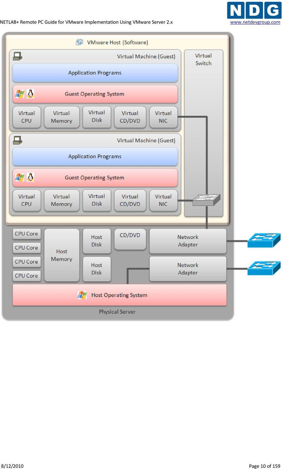
9 NETLAB+ provides remote PC access solutions for both virtual machines and real standalone PCs. However, due to the rapid progress of virtualization technology and the numerous benefits it provides, NDG recommends that all new remote PCs be implemented using virtual machines. New development and support for standalone PC interfacing is no longer provided by NDG. 1.4 What Does VMware Provide? VMware provides virtualization server software. The software abstracts computing resources so that several PCs or servers can run on the same physical server. Each NETLAB+ remote PC or remote server runs inside of a virtual machine. VMware provides virtual CPU, virtual memory, virtual disk drives, virtual networking interface cards, and other virtual hardware for each virtual machine. VMware also provides the concept of a virtual networking switch. Virtual switches can be connected to real networks via host network adapters, allowing virtual machines to connect to real networks. 8/12/2010 Page 9 of 159


10 8/12/2010 Page 10 of 159
 to incorporate virtual machines (PCs and servers) into the lab environment, and make")
11 1.5 How Do NETLAB+ and VMware Servers Work Together? NETLAB+ interfaces with VMware virtualization servers using protocols and application programming interfaces (API) to incorporate virtual machines (PCs and servers) into the lab environment, and make them remotely accessible in an easy-to-use, intuitive way. It also facilities sharing so that multiple users can access the keyboard, video and mouse of a virtual machine simultaneously. 8/12/2010 Page 11 of 159

12 Here is list of features and benefits provided by NETLAB+, working in conjunction with VMware virtualization servers. The keyboard, video and mouse of each virtual machine can be accessed without a backdoor network or interface on the virtual machine. Access to a virtual machine is proxied through NETLAB+ and the virtualization host system, similar to KVM-over-IP hardware solutions. No special client software (other than Java) is required on the user s computer. NETLAB+ will download its remote PC access application to the client whenever the user clicks on a PC. Multiple users can share access to a virtual machine simultaneously. NETLAB+ multiplexes virtual machine traffic using a single IP address and two TCP ports. It also provides a front-end to the virtual machine environment, so that virtualization servers and virtual machines do not have to be placed on production networks. This significantly increases security and eases firewall administration. If the user has a valid lab reservation, NETLAB+ will proxy client access to the keyboard, video and mouse of the virtual machine. This access is terminated when the lab reservation completes, ensuring that users of different reservations do not interfere with each other. NETLAB+ supports revert to snapshot. Changes to a virtual machine can be discarded at the end of a lab reservation, returning the PC to a clean state. Users can have administrative privileges on a virtual machine without risk. Users may power on, power off, and revert to clean state (scrub) from the NETLAB+ web interface. Users can shutdown and reboot a virtual machine during the lab, without losing changes. Virtual network interfaces on a virtual machine can be tied to real networks in the lab. NETLAB+ provides the framework to separate lab networks from real networks in a secure manner. Virtualization using VMware is performed on separate physical servers, not included with NETLAB+. You can interface with multiple VMware virtualization servers if necessary. 8/12/2010 Page 12 of 159
 is required on the user s computer. NETLAB+ will download its remote PC access application to the client whenever the user clicks on a PC.")
13 Part 2 Planning This section discusses the software and hardware requirements for planning a remote PC deployment using VMware Server 2.x. Objectives What software is required? What hardware is required? How many VMware host servers do I need? 2.1 What Software Is Required? Refer to the numbered diagram above. (1) Your NETLAB+ server must be running version 2009.R1 or later to interface with VMware Server 2.x. (2) Each virtualization server requires a copy of Microsoft Windows 2003 Server. In VMware and NETLAB+ terms, this is called the host operating system. Other Windows host operating systems are supported by VMware. This guide will provide guidance for Windows 2003 Server, which is the recommended host operating system at this time. 8/12/2010 Page 13 of 159

14 (3) Each VMware virtualization server requires a copy of VMware Server, available from Other VMware products are supported (see the table below). All examples and procedures in this guide are specific to VMware Server 2.x. (4) Each virtual machine requires a copy of a supported operating system. In VMware and NETLAB+ terms, this is called a guest operating system. Please refer to the VMware Server documentation to determine which operating systems versions are currently supported. NETLAB+ has been tested with Microsoft Windows and Linux operating systems. Novell Netware is known to have problems with cursor updates, and is therefore not supported at this time. (5) Each virtual machine can run application programs. These are installed on each virtual machine the same way you install software on a real PC Product Licensing For the purpose of software licenses, each virtual machine and VMware server system is treated as an independent real PC or server. Please refer to the specific vendor license agreements (and educational discount programs, if applicable) to determine licensing requirements for your virtual machine s software, server software, operating systems, and application programs. 8/12/2010 Page 14 of 159

15 2.1.2 VMware Hosting Product Comparison The following table compares NETLAB+ support and features for selected VMware hosting products. This guide is specific to VMware Server 2.x. Should you decide to use one of the other listed products with NETLAB+, please switch to the respective NETLAB+ guide that is matches the specific VMware product. Product VMware Server VMware ESXi VMware ESX VMware GSX VMware Version 2.x 1.x 3.5 U3 3.5 U3 3.x NETLAB+ Support BETA Supported PLANNED Planned Deprecated (2) Minimum NETLAB+ Version 2009.R R1 TBD Architecture Hosted Hosted Hypervisor Hosted Minimum VMware Version Required U3 3.1 VMware Versions Tested by NDG U Host Operating System Required Windows Windows No Windows Windows Server O/S Versions Tested n/a Linux Server O/S Versions Tested n/a (1) n/a (1) n/a n/a (1) NETLAB+ Feature Support: Remote PC Viewer Yes Yes Yes Yes Power On / Off Yes Yes Yes Yes Revert to Snapshot (scrub) Yes Yes Yes Yes (1) VMware Server for Linux or VMware GSX for Linux is not currently supported or documented by NDG. However, you may run Linux as a guest operating system on virtual machines. (2) VMware GSX has been replaced by VMware Server 1.x and VMware Server 2.x. 8/12/2010 Page 15 of 159

16 2.1.3 NETLAB+ Support Summary for VMware Server 2.x NETLAB+ Support Status BETA Minimum NETLAB+ Version Required NETLAB R1 VMware Server Minimum Version Required VMware Server 2.0 VMware Server Versions Tested VMware Server 2.0 (Build ) Windows Host Operating Systems Tested Windows Server 2003 Linux Host Operating Systems Tested (1, 2) Guest Operating Systems Tested Windows Minimum Number of Virtual Machines (on each VMware server host) NDG does not currently support Linux as a host operating system for VMware Server. XP (x86, 32-bit) 10 * * With adequately sized hardware. Maximum Number of Virtual Machines (on each VMware server host) 10 ** ** The maximum is determined by hardware and the number of virtual switches required. See known issue in section Number of Virtual Switches Supported 10 max See known issue in section NETLAB+ Supported Features Remote PC Viewer Power On Power Off Revert to Snapshot (scrub) (1) Please refer to the VMware Guest Operating System Installation Guide for specific product support, installation instructions and known issues. (2) Older 32-bit processors will only support 32-bit guest operating systems. A 64-bit processor is required for 64-bit guest operating systems. 8/12/2010 Page 16 of 159
 NDG does not currently support Linux as a host operating system for VMware Server. XP (x86, 32-bit) 10 * * With adequately sized hardware.")
17 2.1.4 NETLAB+ Known Issues for VMware Server 2.x In this section, we will discuss several known issues encountered when using VMware Server 2.x with NETLAB Virtual Switch Limit VMware Server 2.x for Windows supports 10 virtual switches per server. This is a hard limit. Count the number virtual switches that are required by each pod. This number cannot exceed 10 per VMware Server. This limit may affect the number of virtual machines that can be run on one VMware server and the number of servers required. If you are using one of the standard NETLAB AE pods, section 2.3 of this guide provides the virtual machine count and virtual switch count for each pod type. A high-end system capable of hosting 20 or more virtual machines may be wasted if the virtual switch count limit of 10 effectively limits you to a much smaller number of virtual machines. The following table discusses three common scenarios and the possible impact of the 10 virtual switch limit. Scenario No Networking. Your virtual machines do not utilize virtual networking or virtual switches. Impact Virtual switches will not be a limiting factor in the number of hosted virtual machines. 1:1 Ratio. The pod design(s) requires that each virtual machine have its own dedicated virtual switch. Shared Virtual Switches. The pod design(s) has virtual machines that share a virtual switch. The number of possible virtual machines on one server is exactly 10 (with adequate hardware). If your pod designs (topologies) have virtual machines that share a virtual switch, then 10 or more virtual machines per server are possible, provided no more than 10 virtual switches are used and the hardware can support the total number of virtual machines on the server. Workaround. Consider using one of the supported VMware ESX/ESXi products listed in section These products support more virtual switches per server, allowing you to place and run more virtual machines and virtual switches on fewer high-end servers. 8/12/2010 Page 17 of 159

18 Continuous High CPU Utilization Causes Timeouts Continuous high CPU utilization at or near capacity on all processor cores cause API connection timeouts. This in turn may cause automated operations performed in NETLAB+ to fail. Causes. Running too many active virtual machines on one server, and/or using a server with inadequate hardware resources. Workaround #1. Add additional VMware servers and divide the workload. Workaround #2. Upgrade server CPU and memory. Additional CPU speed, processor cores and memory are usually helpful. See the hardware discussion in the later section for additional guidance. Workaround #3. Consider using one of the supported VMware ESX/ESXi products listed in section These products provide more control over CPU resource allocation and can be configured to dedicate processing cycles to system tasks NETLAB+ Not Tested With All Guest Operating Systems VMware provides a Guest Operating System Installation Guide that contains a list of supported guest operating systems and the known issues for each. Not all operating systems in this document have been tested with NETLAB+. We recommend that you thoroughly test each unique guest operating system in the NETLAB+ environment prior to production deployment. In particular, you should install the VMware Tools on the guest operating system, and then use the NETLAB+ Remote PC Viewer to test for proper functioning of the keyboard, mouse, mouse cursor, and screen updates NETLAB+ Does Not Support Novell Netware Novell Netware as a guest operating system is not supported by NETLAB+ at this time. There are known issues with cursor updates, making remote access unusable NETLAB+ Does not Support DLink Network Cards DLink network cards and/or chipsets are not supported. NDG has verified that the DLink driver has an MTU problem when used with VMware virtual switches. This problem will break almost all labs. 8/12/2010 Page 18 of 159

19 NETLAB+ Does not Support Broadcom Networking Adapters We strongly discourage the use of Broadcom networking adapters due to a problem with the configuration utility and the use of VLANs. We recommend upgrading to an Intel Networking Adapter for the inside interface (see section 2.1.3). BACS configuration requires teaming. Certain teaming modes will absolutely not work since they can result in these undesirable conditions: Duplicate IP addresses on control devices. Duplicate MAC addresses on virtual machines in the lab. Generic trunking mode is the only known mode that appears to work. If you already have Broadcom Adapters and wish to pursue experimental use of them, refer to Appendix E. Broadcom Adapters may be used for the outside interface (section 3.5) Intel PROSet Device Manager Tabs Not Visible Through Terminal Svcs. Intel PROSet for Device Manager tabs are not visible through Terminal Services when viewed through Microsoft Internet Explorer. The tabs are visible when a user is logged on locally to the Server. Access to the Device Manager tabs is necessary to create VLANs from Remote Desktop (see section 3.2). This issue can be resolved by changing the default user account from "interactive user" to a user with administrative rights (solution for Windows XP and Windows 2003 server): On the target system, select Start Run. Type dcomcnfg in the text field and click OK. The Component Services Console Root window will open. In the left pane, double-click Component Services Computers My Computer DCOM Config. In either pane, Right-click NCS2Prov Properties. The DCOM configuration properties window will open. In the NCS2Prov Properties window, click the Identify tab. Change the user account to "the launching user". Click OK to exit the NCS2Prov Properties window. Close the Component Services window. Please refer to this Intel support page for more information. 8/12/2010 Page 19 of 159

20 2.1.5 Upgrading From VMware Server 1.x to 2.x The management interfaces, APIs, and virtual machine settings for VMware Server 2.x have changed significantly from version 1.x, which has required NDG to develop this separate guide. Configuration changes to both NETLAB+ and virtual machine settings are required when upgrading a virtual machine from 1.x to 2.x. Appendix D documents the necessary changes. 8/12/2010 Page 20 of 159

21 2.2 VMware Host Hardware Requirements At this point, you have decided that VMware Server 2.x is the appropriate product to host your virtual machines. (If not, please switch to the respective NETLAB+ guide that is matches the specific VMware product.) Henceforth, references to VMware, VMware host system and VMware server in this document refers to a server running VMware Server version 2.x virtualization software. Next, we will explore hardware requirements. Remote PCs are implemented on one or more VMware host systems (separate from the NETLAB+ server). The following table is a list of recommended hardware for VMware Server. Servers that do not meet the minimum requirements listed may work, but may encounter performance issues and/or lack support for certain guest operating systems. Please consult the VMware Server User s Guide for details, particularly if you wish to run 64-bit guest operating systems. Processor(s) Recommended Minimum / Features x86-64 compatible (Intel, AMD) 4 or more cores 2.33Ghz per core Intel -specific features: Intel 64 (formerly EM64T) 1,2 Intel-VT (Vanderpool) AMD-specific features: AMD64 revision D or later 1,2 AMD-V (virtualization) Notes Examples that meet minimum: Intel Xeon E5410 (Quad core) 4 Intel Core i7 940 Intel Core i7 920 Intel Xeon X3350 Intel Xeon X3330 Intel Core 2 Quad Q9650 Intel Core 2 Quad Q9550 Intel Core 2 Quad Q9450 Intel Core 2 Quad Q6700 AMD Phenom II X4 940 Memory 4 GB (minimum)*** *** 4GB is the maximum supported by the 32-bit version of Windows Server 2003/2008 Standard Edition. The 64-bit version of Windows Server 2003/2008 Standard Edition will support up to 32GB of ram. Disk 3 320GB 1 TB, RAID 1 or RAID 5 See note 3 below concerning RAID. 8/12/2010 Page 21 of 159
22 Network Interfaces Dual (2) 100/1000 Ethernet with 802.1q Supported Interfaces: Intel server adapter (825XX chipset) with Advanced Network Support (ANS) features Examples in this document are based on the Intel PROSet configuration tools. DLink cards are not supported. (see section ). Unsupported: All DLink cards (see ) Broadcom adapters/chipsets (see ) Host Operating System Microsoft Windows Server 2003 *** *** The 32-bit version supports a maximum of 4GB of RAM. For more than 4GB (up to 32GB), consider using the 64-bit version. (1) x86-64 should not be confused with the Intel Itanium (formerly IA-64) architecture, which is not compatible on the native instruction set level with the x86 or x86-64 architecture. (2) VMware provides a standalone utility that you can use without VMware Server to perform the same check and determine whether your CPU is supported for VMware Server virtual machines with 64 bit guest operating systems. You can download the 64 bit processor check utility from (3) VMware ESX/ESXi only supports hardware RAID. If you plan to upgrade from VMware Server to VMware ESX/ESXi in the future, be sure the RAID controller is supported by ESX/ESXi. Please note that the on-board RAID in many motherboards is actually software RAID (or fake RAID), because the actual RAID functions are performed by device drivers running on the host operating system. (4)This hardware was used by NDG as the 2009 test platform. 8/12/2010 Page 22 of 159
23 2.3 How Many VMware Server Host Systems Do I Need? The number of VMware host systems and memory requirements vary based on the lab topologies and number of pods you want to implement. NDG recommends no more than 10 to 12 virtual machines per server with hardware meeting the requirements in section 2.2. Each virtual machine uses CPU cycles and memory on the server. VMware Server supports up to 4 virtual machines per CPU core. The table below shows a hypothetical allocation of processor cores for virtual machines and other system tasks. You do not actually configure this; the operating system will do this dynamically based on workload. CPU Core #1 CPU Core #2 CPU Core #3 CPU Core #4 VM1 VM2 VM3 VM4 VM5 VM6 VM7 VM8 VM9 VM10 VM11* VM12* Host Operating System, VMware, and API processes * VM11 and VM12, assuming the virtual switch limitation of 10 was not exceeded by topology requirements. If you have more than one ESXi host server, consider spreading the VMs from each pod across all of host servers. This will evenly spread the load on critical system resources for each ESXi host (processing and memory). Running too many virtual machines may starve the host operating system and/or VMware Server APIs. This may lead to timeouts and task automation failures in NETLAB+. If a single VMware host is shared among multiple pods and the VMware host does not meet the requirements from section 2.2, users from one pod may notice a substantial delay when the reservation begins/ends from another shared pod. When a reservation begins, NETLAB+ instructs the VMware host server to power on or resume all Virtual Machines represented in that lab topology. When this occurs, the VMware host may experience a high CPU load for several minutes. This can result in sub-optimal and even unresponsive communications for those NETLAB+ users logged in from a different pod, accessing Virtual Machines hosted by the same VMware server. 8/12/2010 Page 23 of 159
24 Step-By-Step Guidance Step 1. Carefully study your lab topologies and determine the number of virtual switches and virtual machines required by each pod. The requirements for several NETLAB AE pods shown below assume that you are implementing all PCs supported by the pod. The following table shows some of the pods that support virtual machines in NETLAB AE. For an updated list of NETLAB AE topologies, please view the lab topologies page. Maximum Virtual Switches (VMnet) Maximum Virtual Machines Basic Router Pod v2 (BRPv2) 3 4 Basic Switch Pod v2 (BSPv2) 3 3 Cuatro Router Pod (CRP) 4 5 Cuatro Switch Pod (CSP) 4 4 LAN Switching Pod (LSP) 3 4 Network Fundamentals Pod (NFP) 5 required 2 optional 5 required 2 optional Network Security Pod 2.0 (NSP) 5 7 Step 2. Add up the number of virtual switches and virtual machines used by each pod you are implementing. For example: Pod Name Type Virtual Switches Virtual Machines POD 1 Basic Router Pod Version POD 2 Basic Router Pod Version POD 3 Basic Router Pod Version POD 4 Basic Router Pod Version 1 0 (n/a) 0 (n/a) POD 5 Basic Switch Pod Version POD 6 Network Security Pod (2.0) 5 7 Total /12/2010 Page 24 of 159
25 Step 3. Assign each pod that supports PCs to a VMware host server. Remember, VMware Server 2.x for Windows supports 10 virtual switches per server on Windows Server host platforms. This is a hard limit. In the example from step 2, 17 virtual switches are required. Since you can have up 10 virtual switches per server, you would need at least two VMware host servers for this implementation. Server 1 could accommodate POD1, POD2, and POD3. Server 2 could accommodate POD5 and POD6. Note, POD4 does not support PCs and uses no VMware host resources. VMware Host #1 Example Pod Type Virtual Switches Virtual Machines POD 1 Basic Router Pod Version POD 2 Basic Router Pod Version POD 3 Basic Router Pod Version Total 9 12 VMware Host #2 - Example Pod Type Virtual Switches Virtual Machines POD 5 Basic Switch Pod Version POD 6 Network Security Pod (2.0) 5 7 Total /12/2010 Page 25 of 159
26 Step 4. Based on the pod type and curriculum requirements, determine which guest operating system you will use on each virtual machine. Tabulate the operating system and memory requirements for the host operating system and virtual machines. You should allocate the same amount of memory as you would if standing up a real PC. The following would represent typical choices for VMware Host 1 in the previous example. VMware Host System #1 - Example Pod PC Name Operating System Memory (MB) n/a VMware Host O/S Windows Server POD 1 PC1a Windows XP 128 POD 1 PC1b Windows XP 128 POD 1 PC2 Windows XP 128 POD 1 PC3 Windows XP 128 POD 2 PC1a Windows XP 128 POD 2 PC1b Windows XP 128 POD 2 PC2 Windows XP 128 POD 2 PC3 Windows XP 128 POD 3 PC1a Windows XP 128 POD 3 PC1b Windows XP 128 POD 3 PC2 Windows XP 128 POD 3 PC3 Windows XP 128 Total 2048 (2GB) * * At least 4GB per server is now recommended to support recent mainstream operating system requirements with greater memory requirements. To utilize all available virtual switches on a VMware host system, it is possible to split virtual switches and machines in a single pod across two different VMware hosts. However, you should be familiar with the remote PC and virtual switch layout for each pod before attempting this. 8/12/2010 Page 26 of 159
27 Step 5. Translate the requirements from steps 1 through 4 into an itemized list for each server. The two VMware host systems in the previous examples would require the following items. VMware Host System #1 - Example Quantity Item Role 1 Server server hardware Intel Core i7 920 (2.93 GHz X 4 cores) 2GB RAM Minimum (4GB recommended) 2 x 640GB Hard Disks with RAID1 support Dual (2) Intel Network Interfaces with 802.1q VLAN tag support 1 VMware Server for Windows, Version 2.x virtual machine software 1 Windows 2003 Server - Standard Edition host operating system 12 Windows XP (Home or Pro) guest operating systems VMware Host System #2 - Example Quantity Item Role 1 Server server hardware Intel Core i7 920 (2.93 GHz X 4 cores) 2GB RAM Minimum (4GB recommended) 2 x 640GB Hard Disks with RAID1 support Dual (2) Intel Network Interfaces with 802.1q VLAN tag support 1 VMware Server for Windows, Version 2.x virtual machine software 1 Windows 2003 Server - Standard Edition host operating system 5 Windows XP (Home or Pro) guest operating systems 3 Windows 2000 Server guest operating systems 2 Linux guest operating systems 8/12/2010 Page 27 of 159
28 Part 3 VMware Host System Setup This section describes the initial preparation of a VMware host system running VMware Server 2.x software and Microsoft Windows 2003 Server as the host operating system. After preparation of each host server is complete, virtual machines can be added (as guests) and integrated into the overall NETLAB+ system. Objectives Install and configure Microsoft Windows Server operating system. Create a NETLAB+ management account. Install VLAN drivers and utilities. Configure and connect networking adapters. Install VMware Server software. Prepare system for virtual networking. All tasks in this section are performed on separate dedicated servers that you provide. Do not perform any of the tasks in this section on the NETLAB+ server appliance, as this will delete the NETLAB+ software, requiring you to return it to the factory for reinstallation. 3.1 Install and Configure Microsoft Windows Server Operating System If your system was not preloaded with the Microsoft Windows Server operating system, you should do that now. This guide provides examples based on Microsoft Window Server Other versions may differ slightly. Install the operating system on the physical server per Microsoft installation instruction guides (if not pre-installed) Install Chipset Drivers If you installed the operating system, you may need to install the chipset drivers supplied with the computer and/or motherboard, usually on a CD or DVD. Running Windows without the proper chipset drivers installed may result in poor performance, and/or hardware not being recognized. 8/12/2010 Page 28 of 159
29 3.1.2 Configure RAID Configure your RAID drivers (if necessary) and create your RAID arrays. Software RAID solutions (on board fake RAID) may require that you configure your RAID arrays prior to installing Windows Server and/or require a driver disk during the installation. Ignore this step if your system does not support RAID, or you do not wish to configure RAID Disable IIS (Recommended) If the Microsoft IIS web server is running, you can disable or uninstall it to free up memory and other resources. This component is not required. 8/12/2010 Page 29 of 159
30 3.2 Install Advanced Networking Drivers and Utilities Virtual LAN (VLAN) support is required if you want to bridge your virtual machines to real networks and real lab equipment (such as routers, switches, and firewalls). This section describes the VLAN drivers and management utilities for Intel networking adapters. You can skip this section if your virtual machines do not need to communicate with lab equipment and/or external networks on separate VLANs. VLAN support for Intel networking adapters is provided by the ANS driver (which may be different then the driver provided). VLANs are managed using the Intel PROset software utility. These are packaged together and available for download on the Intel.com website. 8/12/2010 Page 30 of 159

31 For Windows Server 2003 (32-bit), the file name is PRO2KXP.EXE (version 13.5 at the time of this writing). Download and run the installer. Select the PROSet and ANS drivers options as shown below. 8/12/2010 Page 31 of 159
32 3.3 Networking Models Several types of network communication occur to and from the VMware host system. KVM. Provides remote Keyboard/Video/Mouse access to virtual machines, via the NETLAB+ server. API. Provides an interface for NETLAB+ to query and control virtual machines (status, power on, power off, and revert to snapshot). Bridging (optional). Allows virtual machines to connect to real lab devices such as routers, switches, and firewalls. This is accomplished by connecting VMware virtual machines to virtual switches, then connecting virtual switches to Virtual LANs (VLAN) behind NETLAB+ control switches. Although not documented in this guide, physical network adapters (NICs) on the VMware host system may be directly connected to lab devices as an alternative to VLANs, for special applications that require direct unobstructed connectivity between a virtual machine and external lab device. Remote Management (optional). System administrators may wish to manage VMware host servers and virtual machines using Remote Desktop and other remote management protocols. NDG has developed three networking models to facilitate this communication. Inside Networking with High Security (ISEC) Inside Networking with External Management (IMAN) Outside Networking with External Management (OMAN) Please evaluate the three models and choose the one that best fits your situation. Other undocumented models are also possible. NDG recommends: IMAN for most environments. ISEC for high security environments. OMAN for older networking interfaces and drivers that will not support the inside models; otherwise, do not implement this model. 8/12/2010 Page 32 of 159
33 Networking Model ISEC IMAN OMAN Security Excellent Very Good Good, with proper diligence in firewall configuration Manage VMware hosts and virtual machines from remote consoles Required number of Ethernet ports in each VMware server Requires 802.1q VLAN support on inside interface Requires 802.1q support on outside interface Requires native (untagged) VLAN 1 support on inside interface No Yes Yes Yes Yes Yes n/a No No Yes Yes No KVM and API traffic flow Inside network (control switches) Inside network (control switches) Outside network (user LAN) Documented in section The following three sections describe each model in detail. Choose one of the three models and perform the network setup tasks outlined in the corresponding section for each VMware host server. 8/12/2010 Page 33 of 159

34 3.3.1 VMware Host Connectivity Using ISEC This section examines the Inside Networking with High Security (ISEC). ISEC is the most secure of the three models, because all VMware host and virtual machine communication occurs completely behind the NETLAB+ inside interface. Traffic is not routed between the outside and inside. Rather, users communicate with virtual machines using a transparent proxy service running on the NETLAB+ server. This high level of security comes with sacrifice. Server management and virtual machine installations must be done at the system console via CD/DVD. If you would like the ability to manage VMware servers from Remote Desktop and/or load software and files from the campus LAN or Internet, then skip ahead to the IMAN model (section 3.3.2). 8/12/2010 Page 34 of 159
35 Reasons to Choose ISEC (one or more may apply) The highest possible security is required. The outside network is not strongly protected by a firewall, and/or is directly exposed on all ports to campus users. The server only supports one Ethernet port. Remote management is not required. Internet or campus LAN access is not required from the host operating system console. ISEC Limitations ISEC provides no network connectivity to the campus LAN or Internet for remote management, software downloads, or virtual machine installation. VMware servers must be managed from directly connected consoles. Virtual machines must be installed from the host console. Software must be installed from CD/DVD. ISEC Requirements Each VMware Server requires one Ethernet interface. This interface must support 802.1q*, with no VLAN tagging on VLAN 1 (this is called the native or untagged VLAN). * Technically, 802.1q is not needed if you are not interfacing to external networks and real lab devices (i.e. a 100% remote-pc-only configuration). To simplify the documentation and provide consistency, we configure 802.1q in all cases, resulting in a VLAN-ready configuration. 8/12/2010 Page 35 of 159
, KVM, and automation traffic (API) remain behind the NETLAB+ inside interface (i.e. the control switches).")
36 3.3.2 VMware Host Connectivity Using IMAN This section documents the Inside Networking model with External Management (IMAN). IMAN provides a balance between security and manageability. All virtual machine traffic (Bridging), KVM, and automation traffic (API) remain behind the NETLAB+ inside interface (i.e. the control switches). The outside interface on each VMware server provides a path for remote management of the VMware host system and virtual machines. 8/12/2010 Page 36 of 159
37 Reason to Choose IMAN Provides a practical method for managing VMware host systems and virtual machines, while keeping most NETLAB+ and lab communication safely on a private network. IMAN Requirements (all apply) Each VMware Server requires two Ethernet interfaces. The inside interface must support 802.1q with no VLAN tagging on VLAN 1 (this is called the native or untagged VLAN). The outside interface has no special requirements. To provide maximum security, inbound connections to the outside interface on each VMware server should be limited to the IP addresses of trusted management workstations. 8/12/2010 Page 37 of 159
38 3.3.3 VMware Host Connectivity Using OMAN This section documents the Outside Networking model with External Management (OMAN). This method can be used if your VMware Server inside interface is not capable of untagged VLAN frames for VLAN 1. This is usually only an issue with older network drivers. OMAN provides minimal security, unless sufficiently firewalled per the diagram above. If your network interface drivers support a native/untagged VLAN, you are encouraged to use the ISEC or IMAN methods. 8/12/2010 Page 38 of 159
39 Reason to Choose the OMAN The network driver for the inside interface on your VMware server is not capable of removing VLAN tags from VLAN 1, the VLAN used by NETLAB+ for several functions. Limitations Imposed To provide adequate security using this method, the outside network should be a DMZ protected by a firewall or router ACLs. Only the ports designated in the CSS, Connectivity and Firewall Considerations whitepaper should be permitted to ingress this LAN segment (labeled DMZ in the drawing). Requirements Each VMware Server requires two Ethernet interfaces. The inside interface must support 802.1q. The outside interface has no special requirements. 8/12/2010 Page 39 of 159
, unless otherwise noted. Objectives Rename the inside interface for easy identification.")
40 3.4 Inside Interface Tasks In this section we will configure the inside interface on the VMware host system. The tasks in the following sub-sections apply to all networking models (ISEC, IMAN, and OMAN), unless otherwise noted. Objectives Rename the inside interface for easy identification. Unbind protocols from the inside physical interface. Understand the role of VLAN 1 and other bridged VLANs. Use Intel utilities to enable and manage 802.1q VLANs. Create VLAN 1 (IMAN, ISEC) Assign IP address to VLAN 1 (IMAN, ISEC) Connect the inside interface to the control switch. Bring up the inside connection. Verify the link and IP connectivity Open Network Connections Window Navigate to the Network Connections panel: Start Control Panel right click on Network Connections Open Select the detail view: View (menu item) Details The Network Connections Panel should now look like this: 8/12/2010 Page 40 of 159

41 3.4.2 Select and Rename Inside Interface Select an unused physical Ethernet network interface on the VMware host server. Identify the corresponding LAN adapter in Windows Server. Rename this interface to Inside Physical Interface : Right click on the interface and select Rename. Change the name to Inside Physical Interface and press Enter. + 8/12/2010 Page 41 of 159
 from the container interface.")
42 3.4.3 Unbind Protocols from Inside Physical Interface The Inside Physical Interface is only used as container for VLAN sub-interfaces. Since protocols will be defined at the sub-interface level, we unbind all protocols (including TCP/IP) from the container interface. From the Network Connection window, open the properties window for the Inside Physical Interface (renamed in previous task): Right click on Inside Physical Interface Properties. The property window should appear: Unbind the protocols from the interface by un-checking them. In particular, ensure the following protocols are unchecked. UNCHECK UNCHECK UNCHECK Client for Microsoft Networks File and Printer Sharing for Microsoft Networks Internet Protocol (TCP/IP) UNCHECK VMware Bridge Protocol (this item should not be listed unless VMware Server was installed before this stepped) When finished, click OK. This applies the changes. You must do this before continuing to the next step. 8/12/2010 Page 42 of 159
43 3.4.4 Understanding VLAN 1 and Bridged VLANs The number of physical adapters required is greatly reduced by using VLANs. In the ISEC and IMAN models, VLAN 1 is used to transport KVM and API traffic between NETLAB+ and the VMware host operating system. In the OMAN model, KVM and API traffic is transported on the outside interface; VLAN 1 is not used. Bridged VLANs are used to transport network data between virtual machines and real lab equipment. The Inside Physical Interface runs 802.1q and acts as container for VLANs. VLAN 1 corresponds to the native (untagged) VLAN on the control switch. In the next step, you will enable 802.1q and create a VLAN 1 sub-interface (ISEC, IMAN). Later in the document, you will learn how to bridge virtual machines to real equipment using bridged VLANs. 8/12/2010 Page 43 of 159
44 3.4.5 Creating VLAN 1 using an Intel Networking Adapter This section applies to ISEC and IMAN. Skip ahead to section if you are implementing OMAN. In this step, we will create a VLAN 1 sub-interface on the Inside Physical Interface (container interface). The VLAN 1 sub-interface has two unique properties: VLAN 1 is the only sub-interface that will be untagged. All other sub-interfaces (if interfacing to real equipment) will use 802.1q VLAN tagging. VLAN 1 is the only sub-interface that binds the TCP/IP protocol. All other inside sub-interfaces will be bridged using the VMware Bridge Protocol. Return to the Network Properties window for the Inside Physical Interface. Verify that the protocols from step 3 are still unbound (unchecked). Next, click the Configure button. 8/12/2010 Page 44 of 159
 in the VLAN Name field. Click OK.")
45 At least two VLANs must exist before VLAN 1 can become untagged. Therefore, we will create VLAN 3 as a temporary placeholder VLAN prior to creating VLAN 1. To create the placeholder VLAN: Click the VLANs tab. Click the New button. Enter 3 in the VLAN ID field. Enter VLAN3 Placeholder (Bridged) in the VLAN Name field. Click OK. Notice that the Untagged VLAN checkbox is inaccessible. This is the reason we could not create VLAN 1 first. This behavior is specific to Intel. 8/12/2010 Page 45 of 159
 in the VLAN Name field. Click OK. You should now have two VLANs associated with the inside adapter, as shown below.")
46 With a placeholder VLAN in place, we can now create an untagged VLAN 1. Begin creating another new VLAN using the same procedure: For this VLAN, uncheck the Untagged VLAN option. Enter VLAN1 NETLAB Inside (IP Enabled) in the VLAN Name field. Click OK. You should now have two VLANs associated with the inside adapter, as shown below. If so, click OK to save changes and exit from the Connection Properties window. The VLAN ID untagged VLAN reports an ID of 0 on the Intel adapter. This is actually VLAN 1 on the control switch. 8/12/2010 Page 46 of 159

47 Return to the Inside Physical Interface properties window and verify that Internet Protocol (TCP/IP) is still unchecked (if not, uncheck it again). The Intel Advanced Network Services Protocol may have been automatically checked as a result of VLAN creation, and this is OK. As the result of creating VLAN 1 and VLAN 3, you should see two new networking adapters in the Network Connections window. However, the VLAN names you have assigned do not automatically transfer to the windows adapters; they must be renamed manually. Hover the mouse over each adapter until Windows displays a yellow tool tip for the interface. Use the tool tip to identify the VLAN. 8/12/2010 Page 47 of 159

48 Once you have identified the Windows adapters associated with VLAN 1 and VLAN 3, rename the corresponding Windows adapter. ) using the same names you assigned during VLAN creation. Network Connections right click the interface name Rename The Network Connections window should now look like this: VLAN 1 and VLAN 3 interfaces are logical sub-interfaces of the Inside Physical Interface. However, this hierarchy is not reflected in the Windows Network Connections. Windows treats VLAN interfaces as ordinary network adapters. VLAN 3 can be deleted after creating other bridged VLANs for virtual machines. This will be discussed in later sections. 8/12/2010 Page 48 of 159

49 3.4.6 Configure VLAN 1 Protocols and TCP/IP Settings This section applies to ISEC and IMAN. Skip ahead to section if you are implementing OMAN. In this section, we configure the network protocols and TCP/IP settings for VLAN 1: Return to the Network Connections window. Right click on the VLAN1 NETLAB Inside interface to invoke the context menu. Select Properties from the context menu. Uncheck Client for Microsoft Networks. Uncheck File and Printer Sharing for Microsoft Networks. Check Internet Protocol (TCP/IP). Your properties for the VLAN interface should now look like this: 8/12/2010 Page 49 of 159
 Properties window. Click on the radio button choice, Use the following IP address: to assign an IP address manually.")
50 Next, initiate manual IP address and setting assignment for the VLAN 1 interface. From the interface Properties window, select Internet Protocol (TCP/IP) by clicking on the words (not the checkbox). You should now see the Internet Protocol (TCP/IP) Properties window. Click on the radio button choice, Use the following IP address: to assign an IP address manually. Click on the radio button choice, Use the following DNS server addresses: to assign DNS servers manually. You are here: Configure the TCP/IP settings for VLAN 1 using the table on the next page. Do not use the same IP address on more than one server. Do not use (this is assigned to the NETLAB+ server) 8/12/2010 Page 50 of 159

51 VMware Host Server > VLAN1 NETLAB Inside Interface > TCP/IP Properties IP Configuration Interface VLAN 1 (untagged VLAN sub-interface) IP Address st server nd server rd server th server NETLAB+ DO NOT USE Subnet Mask Default Gateway Preferred DNS Server Alternate DNS Server None (leave blank) None (leave blank) None (leave blank) 5 th server 14 th server You are here: Click OK to save your changes. 8/12/2010 Page 51 of 159
52 3.4.7 Establishing the Inside Connection In this section, you will establish a connection between the VMware host inside port and NETLAB+ server. Objectives Select a reserved control switch and port. Configure the control switch port. Bring up the link. Verify VMware host system can connect to NETLAB+ using VLAN 1. Troubleshoot the connection if necessary Allocated Reserved Port on Control Switch for Inside Connection There are several issues to keep in mind when selecting a reserved port. Remember that reserved ports operate in VLAN 1, so there are no consecutive port requirements. Typically, when installing control devices, it is desirable to connect NETLAB+, access servers, switched outlet devices, and all other control switches to Control Switch 1, in a hub and spoke fashion. Please refer to the Installing the Control Plane section of the NETLAB+ Installation Guide for detailed discussion of reserved ports and control devices. For each VMware server you install, the inside connection may be located on any reserved port that is available on a control switch. In most cases, you may have more than one control switch and VMware server. If this is the case, you should try to select a reserved port from the same control switch where the pods associated with the VMware server reside. In some circumstances, your VMware server may be hosting several pods. Consequently, the reserved port may be located on a different control switch, if all links between control switches are also configured as 802.1q trunks and all VLANs are allowed. The most important factor would be keeping the pod gear communication and VMware server communication located on one or two control switches. 8/12/2010 Page 52 of 159
53 Configure Reserved Control Switch Port for Inside Connection One reserved port on the control switch connects to an 802.1q NIC card on the VMware Server. This allows devices in the pod to communicate with virtual machines. The reserved port should be configured as an 802.1q trunk port. Once you have allocated a reserved port on the control switch, connect the VMware Server inside NIC using a straight through CAT5 cable. Configure the switch port as a trunk. Example switch port configuration. Interface number will vary. interface FastEthernet0/23 description inside connection for VMware Server #1 switchport mode trunk switchport nonegotiate no switchport access vlan no shutdown The control switch console password is router. The enable secret password is cisco. These passwords are used by NETLAB+ automation and technical support - please do not change them Configure Trunking Between Multiple Control Switches If the reserved port selected for your VMware server is on a different control switch than the lab equipment pods it is serving, you must ensure that inter-switch links between control switches are configured in trunking mode. Some switches models will automatically form trunks. However, it is recommended that both sides be manually configured as trunk ports per the configuration commands below. Example switch port configuration. Interface number will vary. interface FastEthernet0/24 descriptiontrunk to control switch #2 switchport mode trunk switchport nonegotiate no switchport access vlan no shutdown 8/12/2010 Page 53 of 159
54 Connect Inside Interface and Verify Link After you have configured the reserved the port as described in the previous section, verify your cabling between the reserved port and the VMware Server inside NIC. Check the interface status of the reserved port: netlab-cs1#show interfaces FastEthernet 0/23 FastEthernet0/23 is up, line protocol is up (connected) Verify VLAN 1 Connectivity This section applies to ISEC and IMAN. Skip ahead to section 3.5 if you are implementing OMAN Ping from the server to On the VMware host, open a window for the Command Prompt and ping the inside IP address of the NETLAB+ server ( ). You may also verify the connection by opening a Web browser and accessing the NETLAB+ login page by entering the inside IP address. 8/12/2010 Page 54 of 159
55 The web browser should open to the NETLAB+ login page, allowing you to login using the administrator account. 8/12/2010 Page 55 of 159

56 3.5 Outside Interface Tasks In this section, we will configure the outside interface on the VMware host system. The tasks in the following sub-sections apply only to IMAN and OMAN. ISEC does not use an outside interface, so please skip ahead to the next section if you are implementing ISEC. Objectives Rename the outside interface for easy identification. Unbind protocols that are not needed. Bind the TCP/IP protocol to the outside interface. Assign IP address to the outside interface. Bring up the outside interface. Verify IP connectivity Open Network Connections Window Navigate to the Network Connections panel: Start Control Panel right click on Network Connections Open Select the detail view: View (menu item) Details The Network Connections Panel should now look like this: 8/12/2010 Page 56 of 159

57 3.5.2 Select and Rename Outside Interface Select an unused physical Ethernet network interface on the VMware host server that will be used for the outside interface. Identify the corresponding LAN adapter in Windows Server. By clicking on the interface, Window will provide additional identifying information in the status bar. Rename this interface to Outside Physical Interface : Right click on the interface and select Rename. Change the name to Outside Physical Interface and press Enter Configure Outside Interface Protocols The Outside Physical Interface only runs TCP/IP, unlike the inside physical interface. There is no need to configure VLANs or 802.1q support. 8/12/2010 Page 57 of 159

58 From the Network Connection window, open the properties window for the Outside Physical Interface (renamed in previous task): Right click on Outside Physical Interface Properties. The property window should appear: Bind the protocols you require for outside management of your VMware server. TCP/IP should be checked. AS NEEDED Client for Microsoft Networks. Not recommended on a dedicated VMware host system. AS NEEDED CHECK File and Printer Sharing for Microsoft Networks. Not recommended for a VMware hosts system. Internet Protocol (TCP/IP) UNCHECK VMware Bridge Protocol (this item should not be listed unless VMware Server was installed before this stepped) When finished, click OK. This applies the changes. You must do this before continuing to the next step. 8/12/2010 Page 58 of 159

59 3.5.4 Configure Outside Interface TCP/IP Settings In this section, we configure the network protocols and TCP/IP settings for the outside interface. ISEC does not use an outside interface. This section does not apply to ISEC. Return to the Network Connections window. Right click on the Outside Physical Interface to invoke the context menu. Select Properties from the context menu. Click on Internet Protocol (TCP/IP) to select it. Click the Properties button. Assign TCP/IP parameters for the outside interface as assigned. This interface is connected to a local campus LAN, so be sure to obtain a valid unique IP address from your network administrator. If you are using the OMAN networking model, a static IP address must be assigned because NETLAB+ must connect to this server using the IP address. If you are using IMAN, it is possible to use DHCP, as NETLAB+ does not need to reach the outside interface of your VMware server. 8/12/2010 Page 59 of 159
60 3.5.5 Connect and Verify Connectivity After you have assigned an IP address to the Outside Physical Interface, you should verify connectivity to the NETLAB+ server. Verifying connectivity is especially recommended if you use OMAN. The IP address shown here, is an example; your LAN may have a different address. 8/12/2010 Page 60 of 159
61 Ping the outside IP address of the NETLAB+ server. The IP Address shown here is for example purposes only, your IP address will vary. You may also open a browser and access the NETLAB+ login web page: 8/12/2010 Page 61 of 159

62 3.6 Disable Windows Firewall The following guidance applies only to ISEC. Disable the Windows Firewall function as shown so that KVM and API connections can reach the VMware host server. Windows Firewall is not required for ISEC, and enabling it may cause connections problems that might be difficult to troubleshoot. If you want to run the firewall anyway, ensure that the NETLAB+ inside interface ( ) can make connections to the VMware server inside interface using the following ports: TCP 80, 443, 8222, 8333, 902, 903, 3389, 5900 through 6150, ICMP echo request/reply (ping). This list may be revised in future versions. Disable the firewall until everything is working. 8/12/2010 Page 62 of 159

63 3.7 Enable Remote Desktop (Recommended) Should you require assistance with your server or virtual machine setup, NDG can securely connect to your VMware host, using NETLAB+ as a proxy server. This access is enabled only as needed for each troubleshooting session, and then disabled at the end of the session. Remote Desktop significantly expedites the troubleshooting process, since it allows us to review your host and virtual machine settings very quickly. Enable Remote Desktop on the VMware server host operating system. Start Control Panel System Remote tab Remote Desktop > Enable Remote Desktop on this computer (see illustration below). Ensure that Windows Firewall (if enabled) is not blocking TCP port 3389 on the inside interface if using IMAN or ISEC, or the outside interface if using OMAN. Remote Desktop requires valid credentials. NDG will require the Windows Server administrator account and password to access your host system. NDG may also provide addition configuration instructions, depending on your IP settings and firewall configuration. 8/12/2010 Page 63 of 159
64 3.8 Installing VMware Server Software This section describes the tasks involved in setting up a VMware host system. You may obtain a free download of VMware Server 2.x from VMware, Inc. Go to and complete the registration process to obtain your free copy of the latest version VMware Server 2.x. During registration, you will receive a serial number, which you will later enter during installation. An installation wizard will guide you through the VMware product installation. 8/12/2010 Page 64 of 159
65 You will be required to enter the IP address for KVM and API traffic flow. If you are implementing ISEC or IMAN, use the inside network address of the VMware server. If you are implementing OMAN, use the outside network address of the VMware server. Do not enter a FQDN or host name here (use a static IP address). Do not change the default settings for Server HTTP Port (8222) and Server HTTPS Port (8333). The IP addresses displayed in screenshots serve as examples, your IP address may differ. Click Install to begin the installation process. 8/12/2010 Page 65 of 159
66 When prompted, select Yes to restart your system to allow the configuration changes to take effect. After the system has restarted, click on the VMware server desktop icon. Click OK to acknowledge the security alert. Please be aware that the pages displaying this security alert information on your system may differ slightly, depending on your browser selection. 8/12/2010 Page 66 of 159
67 Select the option to add an exception. Add the exception. 8/12/2010 Page 67 of 159
68 Choose the Get Certificate Option Continue by confirming the security exception. 8/12/2010 Page 68 of 159
69 Once you have confirmed the security exception, the VMware Server login prompt will appear. You may login using your Windows Server Administrator account. 8/12/2010 Page 69 of 159
70 3.9 Creating a NETLAB+ Management Account To use a VMware virtual machine with NETLAB+, a dedicated NETLAB+ management account on the host operating system is required. NETLAB+ will use this account to control virtual machines through the VMware API. You must perform the following task from the administrator account. Using the Windows Computer Management interface, create a dedicated account for NETLAB+ and assign a password. The recommended user name and full name is NETLAB (but this is not required). Check the boxes for Password never expires and User cannot change password. Users New User NETLAB Password never expires is checked, User cannot change password is checked. 8/12/2010 Page 70 of 159
71 3.10 Granting Permissions NETLAB+ must have full access to the VMware Virtual Machines. This will require modifying the permissions settings for the NETLAB+ management account (see section 3.9). Permissions are modified from the Permissions tab of the VMware Infrastructure Web Access page (referred to hereafter as the VI Web Access page), which is displayed after login, (see section 3.8). 8/12/2010 Page 71 of 159
72 Select the NETLAB account and assign All Privileges, as shown. Permissions > User/Group name NETLAB > All Privileges is checked 8/12/2010 Page 72 of 159
73 3.11 Maximizing Available Virtual Switches VMware uses three of its virtual networks (VMnet) to provide special guest services such as NAT and DHCP. By default, virtual networks VMnet0, VMnet1, and VMnet8 are unavailable for external connectivity to lab networks behind NETLAB+. However, if the built-in services are not needed, you can reconfigure and reclaim these virtual networks for external connectivity. From the Start menu of your host machine, select the Manage Virtual Networks option to view the current VMnet settings. Start All Programs VMware VMware Server Manage Virtual Networks 8/12/2010 Page 73 of 159
74 The VMnets are shown on the Host Virtual Network Mapping section of the Virtual Network Editor. NETLAB Academy Edition pods do not utilize the built-in VMware networking services. Therefore, the steps outlined in 0 will maximize the number of available virtual switches that can interface with lab pods. 8/12/2010 Page 74 of 159
75 Part 4 Adding Virtual Machines This section explains how to configure a new VMware Server 2.x virtual machine and the proper settings required for NETLAB+. Repeat this process for each new virtual machine. After completing preparation of each host server as described in Part 3, virtual machines can be added (as guests) and integrated into the overall NETLAB+ system. Objectives Add virtual machines to the VMware server host system. Make virtual machines accessible to NETLAB+ users. The process outlined in this section must be followed for each virtual machine added to the system. 4.1 Creating a New Virtual Machine (VM) Working again from the, VI Web Access: Select the Create Virtual Machine option on the Virtual Machine tab. 8/12/2010 Page 75 of 159
76 Your will be prompted to enter a name for your new virtual machine. Choose a name for your virtual machine very carefully. Here are two recommended naming conventions to consider: [VM NAME] = [POD_X_ PC_Y]: If you do not plan on moving virtual machines from one pod to another, we recommend that you include the NETLAB+ pod number and/or PC ID in the name. [VM NAME] = [SERVER_X _VM_Y]: Another, more flexible naming convention would include the VMware server number and virtual machine number. This method would be useful if you are going to be moving virtual machines from one pod type to another. Select Next to continue. 8/12/2010 Page 76 of 159
77 4.1.1 Selecting the Guest Operating system The Guest Operating system and version of your choice that you will install on your virtual machine must be selected. In this example, Microsoft Windows Server 2003 is selected as the Guest Operating System. 8/12/2010 Page 77 of 159
78 4.1.2 Selecting Memory and Processors Choose the amount of physical memory that will be allocated to the virtual machine. In most cases, you may use the default settings for memory and processors. If memory space is a concern, you may need to select a value closer to the recommended minimum. Please make sure you do not oversubscribe system resources (see section ). 8/12/2010 Page 78 of 159
79 4.1.3 Creating a Virtual Hard Disk Use the default settings to Create a New Virtual Disk for your virtual machine. Specify the disk capacity for this virtual machine. Select a disk size that will be adequate to store the guest operating system and all of its software applications for pod labs. The example below shows a selection of 8GB; your requirements may vary. The use of SCSI drivers in a Windows XP or Windows Server 2003 virtual machine requires a special SCSI driver. You may download the driver from the VMware website. 8/12/2010 Page 79 of 159
80 4.1.4 Adding a Network Adapter In most cases, it will be necessary to Add a Network Adaptor to the virtual machine. If your equipment pod will consist of only one individual PC, a Network Adapter is not necessary. 8/12/2010 Page 80 of 159
81 Select a Network Connection type for this virtual machine. Select Bridged, as shown below, if this virtual machine will connect externally to a NETLAB+ VLAN. Keep the Connect at Power On option set to Yes. If your virtual machine will be connected to an external network, it will be necessary to edit the virtual NIC, after the virtual machine is created (see section 5.3). 8/12/2010 Page 81 of 159
82 4.1.5 Selecting CD/DVD Properties Next, you may use the default option, Use a Physical Drive in order to give the guest operating system access to the CD/DVD drive on the host system which will allow you to install the guest operation system. If you prefer, you may select the option to Use an ISO Image to give the guest operating system access to an ISO image residing on the host file system in order to install the guest operating system. In this example, the option to Use a Physical drive was selected. 8/12/2010 Page 82 of 159
83 If you have selected the option to use a physical drive, you will be prompted to select the CD/DVD drive on your host system that you will use to install the guest operating system. This setting will be edited after the guest operating is installed, as described in section 4.4. The Connect at Power on check box must be checked. 8/12/2010 Page 83 of 159
84 4.1.6 Selecting Floppy Drive Options A floppy drive is not necessary. Select the Don t add a Floppy Drive option. 8/12/2010 Page 84 of 159
85 4.1.7 Selecting USB Controller Options A USB controller is not necessary. Select the Don t Add a USB Controller option. 8/12/2010 Page 85 of 159
86 4.1.8 Verifying the Virtual Machine Configuration Settings Select Finish after verifying the configuration settings displayed on the page. Your virtual machine will now be listed in the virtual machine inventory. 8/12/2010 Page 86 of 159
87 4.2 Setting Snapshot Options NETLAB+ works in conjunction with VMware snapshots to restore a virtual machine to a clean state. This can occur automatically at the end of a lab reservation, or when a user selects the scrub command from the NETLAB+ action tab (see the Action Tab section of the NETLAB+ Instructor Guide). Verify that the snapshot setting for your virtual machine is set to Just Power Off. This setting is accessed in the Commands section by selecting Configure VM. 8/12/2010 Page 87 of 159
88 Select the Snapshot tab and make certain the Just Power Off setting is selected. For scrub operations, NETLAB+ will Revert to Snapshot by using internal calls through the VMware API. This will allow NETLAB+ to restore the PC to a clean state. Use of the Just Power Off setting is specific to VMware Server version 2.x. If you are upgrading to VMware Server 2.x, from VMware server 1.x or GSX, it is necessary to change the power-off option from Ask me to Just Power Off. Please see Appendix D for details. 8/12/2010 Page 88 of 159
89 4.3 Installing a Guest Operating System After you have configured the virtual machine settings, you must install an operating system on the virtual machine. During the virtual machine installation process, you configured to have access to the physical CD/DVD drive on your host system, or to have access to an ISO image. Depending on your selection, insert the operating system CD in the server s CD/DVD drive or access the location of the ISO image. Follow the installation procedure as prompted. Please refer to section 2.1 for information on software requirements and product licensing. 4.4 Editing the Virtual CD/DVD Device If you have configured your virtual machine to access the physical CD/DVD drive on your host machine, make sure to edit the CD/DVD device with the recommended settings. These CD/DVD settings must be edited after installing the guest operating system (see section 4.3). 8/12/2010 Page 89 of 159
90 Uncheck the Connect at power on box. This is necessary to prevent the virtual machine from attempting to connect to the VMware host s CD/DVD device, which could result in undesired properties or boot errors. 8/12/2010 Page 90 of 159
91 You may point the CD/DVD device connection to a unique ISO image on the local VMware host. If you choose this option, make sure each virtual machine you create does not point to the same ISO file. Otherwise, you may see some undesired properties or boot errors. 8/12/2010 Page 91 of 159
92 4.5 Installing the VMware Tools Installation of VMware Tools is required to ensure optimal performance and proper NETLAB+ operation. VMware Tools must be installed after installing the guest operating system (see section 4.3). Your virtual machine must be powered on to install VMware Tools. Select Power On in the Commands section to power on your virtual machine. Select the Install VMware Tools option in the status section. 8/12/2010 Page 92 of 159
93 Assuming you have completed the installation of the guest operating system as described in section 4.3, you may proceed with the install of VMware Tools. 8/12/2010 Page 93 of 159
94 4.6 Setting the Virtual Machine Display Properties for Remote Access For optimal performance and minimal bandwidth consumption, we recommend using the lowest possible resolution setting. The use of 800 x 600 provides a good fit on a typical laptop screen without the need to scroll the display. It is possible, however, that your applications may require a higher resolution, such as 1024 x bit color is required. Display update problems have been observed with the 16-bit setting. The following task assumes a virtual machine running a Windows XP operating system. Adjust accordingly for other operating systems. To set the screen resolution and color quality: Boot the virtual machine. Right click on the display and select Properties. Click on the Desktop tab. Click on the Settings tab. Set screen resolution to your desired resolution (800 x 600 is used in this example). Set color quality to 32-bit (required). 8/12/2010 Page 94 of 159
95 8/12/2010 Page 95 of 159
96 4.7 Adjusting Visual Effects Visual effects must be adjusted to provide minimal bandwidth utilization and to ensure the responsiveness of the remote experience. The following task assumes a virtual machine running a Windows XP operating system. Adjust accordingly for other operating systems. Adjust the visual effects: Right click on My Computer and select Properties. Click on the Advanced tab. Click the Settings button for Performance. Click the Visual Effects tab. Select the radio button to Adjust for best performance. Click Ok to accept changes. 8/12/2010 Page 96 of 159
97 4.8 Disabling the Desktop Background The desktop background must be set to None to provide minimal bandwidth utilization and to ensure the responsiveness of the remote experience. Boot the virtual machine. Right click on the display and select Properties. Click on the Desktop tab. Select None for the Background. 8/12/2010 Page 97 of 159
98 4.9 Adding Software Applications You may now add new software to your virtual machine as required by the lab exercises you plan to use on your pods. Please refer to the Installing New Software in a Virtual Machine section of the VMware Server User s Guide for details Taking a Snapshot of Your Virtual Machine Each time you make changes or install new applications on a virtual machine, be sure to take a new Snapshot. Any changes made to the virtual machine by lab users will be lost when the virtual machine guest operating system reverts to the snapshot: At the end of a lab reservation. When a user selects Scrub from the NETLAB+ Action tab. Take a snapshot by selecting the Take Snapshot option in the Commands section. If you do not take a new snapshot after modifying the configuration file, your changes will be lost the next time the snapshot reverts. Your changes will also be lost if the virtual machine is not powered off when the configuration file is edited. DO NOT take a Snapshot of a Virtual Machine when it is either turned on or suspended. Make sure VM is powered off each time you take a new Snapshot. 8/12/2010 Page 98 of 159
99 4.11 Remote PC Settings (for New Pods) Remote PCs are part of a lab topology, so they must be configured in NETLAB+ when a new equipment pod is added. All settings (except ID) can be modified later. Remote PCs are only available in pods where the network topology indicates the existence of lab PCs. Remote PC settings will appear in the New Pod Wizard when you add an equipment pod that supports remote PCs. Each PC has an ID, type, access method, and operating system setting. All settings (except ID) can be modified later. To modify existing PCs, skip ahead to section For PC/Virtual Machine Type, use the VMWARE Server 2.0 setting for VMware virtual machine implementations using VMware Server version 2.x. This is the correct setting if you are following the procedures outlined in this guide. The Access setting, VNC, allows direct access to the PC s keyboard, video and mouse using the VNC protocol. This setting cannot be altered when VMware Server 2.0 has been selected as the PC/Virtual Machine Type. The Operating System setting specifies an OS for this PC. The availability of a selection does not guarantee compatibility with all labs. NETLAB+ will prompt for additional settings on the next page. 8/12/2010 Page 99 of 159
100 Each virtual machine requires four VMware-specific settings. The IP Address setting is used to connect to the VMware host system. This is the IP address used for KVM and API traffic flow. If you are implementing ISEC or IMAN, use the inside network address of the VMware server. If you are implementing OMAN, use the outside network address of the VMware server. Username specifies an operating system account on the VMware host system. NETLAB+ will use this account to login to the VMware host and control virtual machines through the VMware API (see section 3.9). Password specifies the password associated with the host account (see section 3.9). Configuration File Enter the relative path of the virtual machine configuration file on the VMware host, including datastore. This file name is typically in the form of [datastore] <pc name>/<operating system>.vmx. The name of the configuration file of your virtual machine can be found by selecting the Configure VM section. 8/12/2010 Page 100 of 159
101 The configuration file name is displayed on the General tab. You can copy and paste the full pathname of a VM Configuration file from the VM configuration screen into the NETLAB+ VMware virtual machine settings Configuration File Name field. The use of relative path names is specific to VMware Server 2.x. VMware server 1.0 and GSX require absolute path names. If you are upgrading from VMware Server 1.0 and GSX, you must change your configuration file path names to use relative path names, as shown in the example above. Please refer to Appendix D for details on upgrading to VMware Server 2.x from VMware Server 1.0 and GSX. 8/12/2010 Page 101 of 159
102 4.12 Modifying PC Settings To modify PC settings, or convert an existing PC to use VMware Server 2.x: 1. Take the pod offline. 2. Select the PC from the Pod Management page. 3. Change Type to VMWARE Server 2.0 (if it is not the current setting). 4. Specify the VMware settings (described in section 4.11). If you want NETLAB+ to return the PC to a clean state after a lab reservation, make sure revert to snapshot is checked. Recall from section 4.2 that the virtual machine snapshot power-off option must also be set to Just Power Off. 8/12/2010 Page 102 of 159
103 4.13 Configuring Remote Display Options To allow NETLAB+ users to access the keyboard, video, and mouse of a virtual machine, you must add three RemoteDisplay statements to the virtual machine s configuration file. 1. Access the detailed remote PC settings from the NETLAB+ Pod Management page (as described in section 4.11). 2. Obtain the VMware Guest VNC Settings (automatically computed by NETLAB+). The settings for this example are highlighted in the picture below (your settings will vary). 3. From the VMware management console, make sure the PC is powered OFF or suspended. 4. Working from the VI Web Access page, select your virtual machine in the Inventory list and the click on Configure VM in the Commands section. 8/12/2010 Page 103 of 159
104 5. Select the Advanced tab and scroll down to the Add New Entry function located in the Configuration Parameters section. 8/12/2010 Page 104 of 159
105 6. Add each of the three VMware guest VNC settings as configuration parameters. If you make an error while keying in a configuration parameter, you may need to remove the virtual machine from the inventory (without deleting it from the disk), edit the VMX file and re-add, or restart the VMware Server services, by following the procedure described in Appendix F Taking a New Snapshot of the Virtual Machine After completing the task of adding the configuration statements to the configuration file you must take a new snapshot of your virtual machine. Select the Take Snapshot option in the Commands section. If you do not take a new snapshot after modifying the configuration file, your changes will be lost the next time the snapshot reverts. Your changes will also be lost if the virtual machine if not powered off when the configuration file is edited. 8/12/2010 Page 105 of 159
106 4.15 Verify the Virtual Machine After your virtual machine is configured, perform the following tasks to verify the API is functioning. The Pod Test only verifies the remote display parameters and the function of the VMware API. The Pod Test does not test network connectivity to networking gear such as routers, switches and firewalls. The process required to bridge your virtual machines to real networks and real lab equipment (such as routers, switches, and firewalls) is described in detail in Part Run a pod test. NETLAB+ will check your settings and verify that the API is working. 2. Bring the pod back online. 3. Login to an instructor account and create a lab reservation to test your virtual machine(s). 4. On the Status tab, your virtual machines should be online. 8/12/2010 Page 106 of 159
107 5. Open a connection to the PC by clicking on the device in the topology, the status tab, or connections tab. This will bring up the NETLAB+ Java viewer (assuming you have Java installed). 8/12/2010 Page 107 of 159
108 6. Test the VMware API. Power off the machine from the Action tab. If you had a connection open, it should drop. If you reconnect, NETLAB+ should know the PC is powered off (by obtaining the status of the virtual machine via the VMware API). 7. From the Action tab, power the virtual machine back ON. Wait a minute for the machine to startup. You should now be able to reconnect. 8/12/2010 Page 108 of 159
109 8. Test the scrub device/ snapshot feature. Make some changes to the PC (i.e. move some icons around and create some files). Select Scrub Device on the Action tab. The PC will reboot and your connection will drop (this is normal). Wait a minute for the machine to restart. You should now be able to reconnect, and your previous changes should be gone. 8/12/2010 Page 109 of 159

110 Part 5 Connecting Virtual Machines to Real Lab Devices This section focuses on the establishing communication between virtual machines and lab devices in the topology. You can skip this section if your virtual machines do not need to communicate with lab equipment and/or external networks on separate VLANs. Virtual LANs (VLANs) are used to bridge your virtual machines to real lab equipment (such as routers, switches, and firewalls). These VLANs are implemented on control switches and managed by the NETLAB+ software. 8/12/2010 Page 110 of 159
111 The following objectives will make more sense after you have added a new equipment pod. Objectives Determine which VLAN numbers are used by your pod. Create the proper VLAN adapter using an Intel networking adapter. Uncheck the unused Protocols from Network Properties. Bind each VLAN adapter to an available VMware virtual switch (VMnet). Configure a Virtual Switch to use correct VMnet (using VI Web Access). Take a final snapshot to save changes made to the VM configuration. 5.1 Determining Which VLAN Numbers Are Used by Your Pod The VLAN adapters you must create for you virtual machines will vary based on which pods you have added to your NETLAB+ server. A VLAN Pool is the consecutive range of VLANs used by NETLAB+. Each pod has a unique VLAN pool and the actual VLAN numbers will be unique for each pod. You must determine which VLAN numbers used by NETLAB+ must be trunked to the VMware host. There are resources available to assist you in determining which VLAN numbers are used: If you are implementing a standard NETLAB+ Academy Edition pod, you may refer to the Configuring VMware and Virtual Machines section of the appropriate pod-specific guide to obtain this information, including the VLAN Offset Reference Table specific to your pod. The examples in the subsections below provide more detail regarding this process. If you are implementing a custom pod design, consult with the individual who created the pod design and refer to the Pod Design Theory section of the NETLAB+ Pod Design Guide for additional information. VMware Server virtual network adapters and virtual LAN switches (VMnets) are used to connect virtual machines to the pod. Depending on the pod design, some virtual machines may share the same VLAN. Without the proper VLAN adapter mapped to an available VMnet, the connections between pod devices and/or virtual machines will not function properly. 8/12/2010 Page 111 of 159
112 5.1.1 Determining VLANs Example 1 Cuatro Router Pod In this example, we see that a Cuatro Router Pod uses 4 VMnets in the required configuration. Since VMware Server supports 10 virtual switches, it is possible to host up to 2 complete Cuatro Router Pods on a single VMware Server. Each virtual switch is mapped to a specific VLAN and bound to the VMware inside 802.1Q NIC card. The actual VLAN numbers used are based on the pod s ID number. PC1a and PC1b share a common VMnet and VLAN. Each NETLAB AE pod is automatically assigned a pool of unique VLAN numbers. You must determine which VLAN numbers correspond to each virtual switch on the VMware server. 8/12/2010 Page 112 of 159
113 Step 1. Determine the Base VLAN for the pod. The base VLAN and VLAN pool numbers are displayed on the Pod Management page in the Control Switch table. Please see the Verifying Your Settings section of the NETLAB+ Administrator Guide for details on accessing the Pod Management page to find the base VLAN number for your pod. An example of the VLAN pool information available on the Pod Management page. In this example, pod 7 uses VLANs The base VLAN is 160. Your VLAN numbers will vary. Step 2. Determine the actual VLAN number for each virtual network. Add the base VLAN to the offsets in the table below. In this example, the VLAN Offset Reference Table from the NETLAB AE Cuatro Router Pod Guide is used. Consult the appropriate pod-specific guide to obtain the information for your pod. The base VLAN value used below (160) is an example, the base VLAN of your pod will vary. VLAN Offset Reference Table Cuatro Router Pod Virtual Machines PC1a PC1b Virtual Switch (VMnet) Offset (add to base VLAN) Actual VLAN Example R1 VMnet + 0 = = 160 PC2 PC3 PC4 R2 VMnet R3 VMnet R4 VMnet + 2 = = = = = = 166 In this example, we have determined that we must create VLAN adapters for VLANs 160, 162, 164, and /12/2010 Page 113 of 159
114 5.1.2 Determining VLANs Example 2 Cuatro Switch Pod In this example, we observe that the Cuatro Switch Pod uses 4 VMnets in the required configuration. Since VMware Server supports 10 virtual switches, it is possible to host up to 2 complete Cuatro Switch Pods on a single VMware Server. Each virtual switch is mapped to a specific VLAN and bound to the VMware inside 802.1Q NIC card. The actual VLAN numbers used are based on the pod s ID number. PC1a and PC1b share a common VMnet and VLAN. Each NETLAB AE pod is automatically assigned a pool of unique VLAN numbers. You must determine which VLAN numbers correspond to each virtual switch on the VMware server. 8/12/2010 Page 114 of 159
115 Step 1. Determine the Base VLAN for the pod. The base VLAN and VLAN pool numbers are displayed on the Pod Management page in the Control Switch table. Please see the Verifying Your Settings section of the NETLAB+ Administrator Guide for details on accessing the Pod Management page. An example of the VLAN pool information available on the Pod Management page, your VLAN numbers will vary. In this example, Pod 10 uses VLANs The base VLAN is 190. Step 2. Determine the actual VLAN number for each virtual network. Add the base VLAN to the offsets in the table below. In this example, the VLAN Offset Reference Table from the NETLAB AE Cuatro Switch Pod Guide is used. (Consult the appropriate pod-specific guide to obtain the information for your pod) The base VLAN value used below (190) is an example, the base VLAN of your pod will vary. VLAN Offset Reference Table Cuatro Switch Pod Virtual Machines Virtual Switch (VMnet) Offset (add to base VLAN) Actual VLAN Example Host A ALS1 VMnet + 0 = = 190 Host B ALS 2 VMnet + 1 = = 191 Host C DLS 1 VMnet + 2 = = 192 Host D DLS 2 VMnet + 3 = = 193 In this example, we have determined that we must create VLAN adapters for VLANs 190, 191, 192, and /12/2010 Page 115 of 159
116 5.2 Creating VLAN Adapters Based on the VLAN numbers you identified in the previous section, follow the steps described in the subsections below to create each of the VLAN adapters required Create a Proper VLAN Adapter using an Intel Adapter Navigate to the Network Connections panel: Start Control Panel right click on Network Connections Open You will create a VLAN sub-interface on the Inside Physical Interface (container interface). Open the Network Properties window for the Inside Physical Interface. Next, click the Configure button. 8/12/2010 Page 116 of 159
117 To create a VLAN: Click the VLANs tab. Click the New button. Enter the appropriate VLAN ID as per section 5.1. Enter a descriptive name(i.e. pod number and remote pc number) for the VLAN Name field. Click OK. 8/12/2010 Page 117 of 159
118 5.2.2 Uncheck the Unused Protocols from Network Properties After you add your pod VLANs, make sure VMware Bridge Protocol is the only selected protocol. Start Control Panel right click on Network Connections Open Select the detail view. View (menu item) Details 8/12/2010 Page 118 of 159
119 Right Click your VLAN name Properties. VMware Bridge Protocol must be checked. All others that you are able to uncheck should be unchecked. There may be checked items that are required by the driver that you do not have the option of un-checking (this is ok). Traffic should be bridged, not routed, between equipment pods and VMware virtual machines. Therefore, it is important to unbind TCP/IP and Microsoft client protocols from each of the 802.1q sub-interfaces on the VMware host adapter that are associated with lab VLANs. 8/12/2010 Page 119 of 159
120 5.3 Mapping VLAN interfaces to available Virtual Networks (VMnets) The VMware Virtual Network Editor is used to bridge virtual networks in VMware to real networks in NETLAB+ (review section 5.2). On a Windows VMware Server host, you may create up to 10 virtual networks (VMnet) that can connect one or more virtual machines to a VLAN in NETLAB+. By default VMnet0, VMnet1, and VMnet8 provide special functions. See Appendix A for a description of how to reclaim them for external connectivity to NETLAB+. To allocate a virtual switch and connect to a VLAN in NETLAB+: Access the Virtual Network Editor (see 3.11) and select the Host Virtual Network Mapping tab. Assign an available VMnet to a VLAN interface. Each VLAN created, as per section 5.2, should be available in the drop down lists. This image uses VLAN 153 as an example; your selections will vary. If the VLAN interfaces do not appear from the drop down list, the system will require a reboot to initialize the newly created adapters. Any VLAN interfaces created during the process described in section 5.2 only show up in the VMware Virtual Network Editor after the server (or VMware host) has been rebooted. 8/12/2010 Page 120 of 159
121 5.4 Configure a VM to use the correct VMnet (using VI Web Access) Once you have added the proper VLANs and mapped them to an available VMnet, you are ready to configure each virtual machine to use the appropriate VMnet. 1. From the VI Web Access page, select the virtual machine from the inventory list and locate Network Adapter 1 in the Hardware Section of the Summary tab. 2. Click on Network Adapter 1 and select Edit. 3. Review the available VMnet selections in the Network Connections section. Your VMnets mapped as per section 5.3, should appear as pulldown selections. 8/12/2010 Page 121 of 159
122 VMnet selections will not appear until you have mapped a VLAN interface to a VMnet (using Virtual Network Editor). If you have mapped your VLANs using the Virtual Network Editor and the VMnets do not appear from the drop down list, the system will require a reboot to update the VMware Server services. 4. Select the proper VMnet for this VM. If you do not select the correct VMnet, your virtual machine will not use the proper VLAN adapter and cannot communicate with lab gear during a lab reservation. The proper VMnet to choose for the virtual machine is the VMnet that was mapped to the VLAN of the virtual machine (see section 5.3). 5. Take a final snapshot of your virtual machine (see section 4.14). 8/12/2010 Page 122 of 159
123 5.5 Deleting the Placeholder VLAN 3 Recall from section that VLAN 3 was created as a temporary placeholder. This was necessary in order to create untagged VLAN 1, since 2 VLANs must exist before VLAN 1 can become untagged. VLAN 3 may now be deleted. Return to the Network Properties window for the Inside Physical Interface (see section 3.4.5). Next, click the Configure button. Click the VLANs tab. Select VLAN3 Placeholder (Bridged) Click Remove to delete the VLAN. 8/12/2010 Page 123 of 159

124 Select Yes to confirm the delete of VLAN 3. 8/12/2010 Page 124 of 159
125 Part 6 Verifying Connectivity and Troubleshooting This section provides guidance on common troubleshooting issues associated with the implementation of VMware Server with NETLAB+ and guidance on verifying connectivity after installation. Please review the material in this section prior to contacting NDG for customer support (see Appendix C). Objectives Verifying connectivity between virtual machines and lab gear. Reviewing and/or modifying virtual machine settings for existing virtual machines. Identify and resolve the most frequently encountered VMware issues. 6.1 Verifying Connectivity Between Virtual Machines and Lab Gear We strongly encourage verifying the connectivity between your virtual machines and lab gear after completing the processes outlined in Part 5, using the method described in this section. The troubleshooting methods shown here can also aid you in determining why a remote PC in a NETLAB+ pod is having network connectivity problems. Verify that your pod is online (see the Equipment Pods section of the NETLAB+ Administrator Guide) and that the pod passes the pod test (see section 4.15). The example below illustrates a NETLAB AE BRPv2 topology installed as Pod #5 on Control Switch #4: BRPv2 Lab Device Device Port Control Switch #4 Port NETLAB+ Pod VLAN Router 1 fa 0/0 fa 0/1 140 fa 0/1 fa 0/2 141 PC1a virtual NIC fa 0/ PC1b virtual NIC fa 0/ Router 2 fa 0/0 fa 0/3 142 fa 0/1 fa 0/4 143 PC2 virtual NIC fa 0/ Router 3 fa 0/0 fa 0/5 144 fa 0/1 fa 0/6 145 PC3 virtual NIC fa 0/ /12/2010 Page 125 of 159
126 In order to test the connectivity between remote PCs and neighboring lab devices, using the above example, you may follow these steps, using an Instructor Account (see the Manage Accounts section of the NETLAB+ Administrator Guide). 1. Make a lab reservation. 2. Configure IP addresses on the remote PCs and neighboring lab devices you will be testing. 3. In the example above, PC1a and PC1b should share the same VMnet, so they should be able to ping each other. If they cannot ping each other, then you should review the following: What VMnet is PC1a and PC1b using? (refer to 5.3) Is there a firewall installed or enabled on the virtual machine? 4. To verify the connectivity between remote PCs and neighboring lab devices, you should test the following: Ping from PC1a to R1 and vice versa. Ping from PC1b to R1 and vice versa. Ping from PC2 to R2 and vice versa. Ping from PC3 to R3 and vice versa. 5. If you can ping from a remote PC to a neighboring lab device, but cannot ping from the lab device to the remote PC, then you may want to determine if there is a firewall installed or enabled on the virtual machine. 6. If any of the tests from step 4 completely fail (you cannot ping from remote PC to neighboring lab device and vice versa), then you will need to analyze the network traffic on the control switch. Using the above example, perform the following steps: Connect a PC or terminal to the console port of the control switch. Type show vlan or show vlan brief to view the VLAN status on the control switch. 8/12/2010 Page 126 of 159
127 The control switch console password is router. The enable secret password is cisco. These passwords are used by NETLAB+ automation and technical support - please do not change them. During a lab reservation, you will notice the active lab ports and their VLAN assignments. From the example above, Pod #5 is a BRPv2 installed on ports fa0/1 through fa0/6 on Control Switch #4. The base VLAN for this pod is 140. On the control switch, type show interfaces trunk to view the trunk information. 8/12/2010 Page 127 of 159
128 This command will reveal whether or not you have properly configured the control switch port that connects to the VMware trunking port. The following shows the proper configuration for the example above on port 23 of Control Switch #4. 8/12/2010 Page 128 of 159
129 Obtain the MAC address of a virtual machine by using the ipconfig /all command at the command prompt of the virtual machine. On the control switch, type show mac-address-table dynamic. Use the MAC address table to verify: 1) whether the MAC addresses of the remote PCs are in the table and 2) if these MAC addresses are in the correct VLANs. 8/12/2010 Page 129 of 159
130 7. If any of the tests from step 4 completely fail (you cannot ping from the remote PC to a neighboring lab device and vice versa), and the MAC address of a remote PC is either: a. Not in the correct VLAN or b. Does not show up in the control switch MAC address table, please review the VLAN and VMnet settings for your NETLAB+ pod very carefully. Refer to Part 5 for complete details. Possible error conditions include: An incorrect VLAN ID was entered when creating a VLAN interface. No VLAN or an incorrect VLAN was mapped to a VMnet using the Virtual Network Editor The wrong VMnet was configured for the Virtual Machine s configuration (using the VI Web Access page). In this case you would have to take a new snapshot (after correction is applied). The control switch port (for the Inside Connection) is not trunking or not allowing the correct VLANs. If you are in the process of installing a new NETLAB AE pod on your NETLAB+ system, please return now to the respective pod-specific guide for your pod. The final chapters, Testing the Pod, and Finishing Up provide details that will allow you ensure your pod is installed properly and ready for use. 8/12/2010 Page 130 of 159
131 6.2 Review and Modify VM Settings For an Existing Virtual Machine Section 4.1 outlined the creation of new virtual machines using the New Virtual Machine Wizard. This section describes how to verify and/or modify the VM settings of an existing virtual machine for integration with NETLAB+. Using the VI Web Access page, select your virtual machine from the Inventory and click Configure VM in the Commands section. 8/12/2010 Page 131 of 159
132 The settings on the general tab include the Virtual Machine Name, Configuration File, and your selection of guest operating system. The machine and file names shown here are for example purposes, your selections may vary. 8/12/2010 Page 132 of 159
133 Select the Power tab to display the Power settings. Use the default selections for Power settings, as shown in the screenshot below. 8/12/2010 Page 133 of 159
134 Select the Snapshot tab. The When Powering Off option must be set to Just Power Off. If these options are unavailable, check to make sure the Virtual Machine is neither running nor suspended. If this virtual machine must connect to an external network, such as a VLAN behind NETLAB+, you must connect a virtual network interfaces to the desired VMnet (see section 5.4 for details on accessing these settings). 8/12/2010 Page 134 of 159
135 Verify the settings for the CD/DVD drive (see section 4.4 for details on accessing these settings). Uncheck the Connect at power on box. This is necessary to prevent the virtual machine from attempting to connect to the VMware host s CD/DVD device, which could result in undesired properties or boot errors. 8/12/2010 Page 135 of 159
136 You may also point the CD/DVD device connection to a unique ISO image on the local VMware host. If you choose this option, make sure each virtual machine you create does not point to the same ISO file. Otherwise, you may see some undesired properties or boot errors. 8/12/2010 Page 136 of 159
137 6.3 The Most Frequently Encountered VMware Issues If you are experiencing problems with your virtual machines or they are not passing the pod test, please review the following symptoms and resolutions carefully: 1. Symptom: The user runs a pod test and the results indicate that the remote display settings are missing or misconfigured. Additional information regarding error conditions is available by selecting the hyperlinked text within the details section of the pod test results. Resolution: Each virtual machine allocated for a NETLAB+ pod for remote PC access should have the VNC settings saved into the VMX file. This procedure is described in section /12/2010 Page 137 of 159
138 2. Symptoms: a. The pod test is taking an unusually long time, fails to complete or b. You see the following error in the pod test: Resolution: These symptoms are related to incorrect snapshot settings. The Virtual Machine should have the snapshot setting of Just Power Off (see section 4.2). 3. Symptom: You are unable to ping lab gear from the virtual machine. Resolutions: See section 6.1 for an example of a troubleshooting scenario. a. Network traffic should be bridged, not routed, between equipment pods and VMware virtual machines. Therefore, it is important to unbind TCP/IP and Microsoft client protocols from each of the 802.1q subinterfaces on the VMware host adapter that are associated with lab VLANs. Reference section for full details. b. Each virtual machine should have the proper custom VMnet selected and that VMnet should be mapped to the proper VLAN adapter. Reference section 5.3 for full details. c. Disable built-in firewalls on the virtual machine (Windows firewall, for example). 8/12/2010 Page 138 of 159
139 8/12/2010 Page 139 of 159
140 4. Symptom: A Pod test failure indicates API-Fail incorrect user or password. Resolution: Make certain you have created the management account (section 3.9) and you added to proper permissions (section 3.10). 5. Symptom: My keyboard and/or mouse are behaving very erratically (sub as, double letters, or the mouse is very jumpy) when using the NETLAB+ Remote PC viewer. Resolution: Each virtual machine should have VMware Tools installed. Refer to section 4.5 for full details. 6. Symptom: I am using a non-windows guest operating system, and I cannot get the mouse to behave properly. Resolution: Some guest operating systems, such as Linux, require very specific steps to install VMware Tools properly. For example, most Linux VMs require you to run a configuration script to complete the VMware Tools installation. Do not assume that VMware Tools is properly installed without reviewing the guidelines as per the VMware documentation: mmand=show&forward=nonthreadedkc&kcid=340. 8/12/2010 Page 140 of 159
141 7. Symptom: You are in a NETLAB+ reservation and the Remote PC viewer is slightly sluggish in performance. Resolution: Each virtual machine should be adjusted for optimum remote display access (see section 4.6): a. Minimal screen resolution with 32-bit color quality (see sections 4.6). b. Do not use a graphical background. The desktop background should be plain or none (see section 4.8). c. Adjust the visual effects for best performance (each O/S may have different settings, see section 4.7). 8. Symptom: Your virtual machines are giving an UNKNOWN status from the Status tab of a lab reservation in NETLAB+. Resolution: Review the following potential causes: a. We recommend no more than 10 to 12 virtual machines, MAXIMUM, per server that meets the MINIMUM requirements in section 2.2. Each virtual machine uses CPU cycles and memory on the server. As a simple rule of thumb, divide the processor clock speed by the number of virtual machines to determine the speed of each virtual machine in a heavily loaded environment (i.e. all pods are running at the same time and users are working on the PCs). For example, a 3GHz processor could run 10 virtual machines at 300MHz each. This does not account for overhead on the host operating system. If your VMs are running in a heavily loaded environment, the VMware daemon process may stall, hang, or become unresponsive. This could cause requests from the NETLAB+ server to be ignored. This would give an UNKNOWN status for your remote PCs from the Status tab of a lab reservation in NETLAB+. b. Each virtual machine should have their virtual CD/DVD device disabled, (section 4.4). c. Verify each VM setting from section /12/2010 Page 141 of 159
142 Appendix A Using Reserved Virtual Networks for External Connectivity VMware uses three of its virtual networks (VMnet) to provide special guest services such as NAT and DHCP. By default, virtual networks VMnet0, VMnet1, and VMnet8 are unavailable for external connectivity to lab networks behind NETLAB+. However, if the built-in services are not needed, you can reconfigure and reclaim these virtual networks for external connectivity. NETLAB Academy Edition pods do not utilize the built-in VMware networking services. Therefore, the steps outlined below will maximize the number of available virtual switches that can interface with lab pods. Open the Virtual Network Editor (see section 3.11) and select the Automatic Bridging Tab. 8/12/2010 Page 142 of 159
143 1. Click on the DHCP tab. 2. Remove VMnet1 and click Apply. 3. Remove VMnet8 and click Apply. The service status should change to Stopped. 8/12/2010 Page 143 of 159
144 4. Click on the NAT tab. 5. Change VMnet host to Disable and click Apply. The service status should change to Stopped. All ten VMnet virtual networks can now be used to provide connectivity to external VLANs. This process is described in section /12/2010 Page 144 of 159
145 Appendix B Copying VMDK File to Clone Virtual Machines Once you have successfully created a single virtual machine, you may clone this VM to create new VMs as a short cut. This would essentially save the time it takes to install a new guest operating system and VMware Tools. Each guest operating system is fully functional and must meet the vendor's licensing requirements. This short cut is useful only if your NETLAB+ pod VMs are going to have similar virtual machine settings: VM memory size (can be adjusted easily after new copy is created) VM hard disk size (cannot be adjusted easily) VM Operating System (this must be the same if you are cloning) The following steps highlight procedure for cloning your virtual machine to create new VMs. It is assumed you have successfully created a single VM as per Part Create a new Virtual Machine by following the exact steps from sections 4.1 through 4.2. Make sure your new VM has the same hard disk size and VMDK file name as the VM you are copying. Always create a new virtual disk for your VMs; do not use an existing virtual disk (each VM, whether copied or not, should have its own unique virtual hard disk). 8/12/2010 Page 145 of 159
146 2. Copy and Paste the VMDK (VMware virtual disk) file from the directory of the virtual machine you are copying to the directory of the VM you just created (the VM directories should be located in the Virtual Machines directory on your host server). Do not cut, move, or rename the VMDK file. The new VM s virtual disk file (VMDK) will be overwritten by the VMDK file you are copying. If you have not renamed the VMDK files, then the VMDK file names should be the same in both directories. 3. Start the new virtual machine you have just cloned. It should be an exact copy of the VM you copied. Make any necessary changes to the copied VM, to separate it from the copied VM (i.e. if these VMs will be networked on the same subnet, you may want to change the Computer Name or IP settings). 4. Power down the cloned VM and take a snapshot to save your work. 5. Repeat steps 1 through 4 above to clone any further required VMs for your NETLAB+ pods. 6. Perform a pod test (see section 4.15) to verify connectivity. 8/12/2010 Page 146 of 159
147 Appendix C Contacting NDG for Technical Support If you need to contact NDG for support, please be aware that VMware Server is a third party product. NDG cannot transfer a customer to the VMware help desk, but we will do our best to help you setup and operate a remotely accessible PC or server using supported VMware virtualization products on your NETLAB+ system under the following guidelines: 1. The NETLAB+ administrator has thoroughly studied the NDG documentation including this guide, and attempted to install Virtual Machines (VMs) based on NDG recommendations. 2. Remote access to both the VMware Server and NETLAB+ server provides the most effective way for NDG to assists customers. a. NDG provides up to 2 hours of support assistance for customers with current NETLAB+ support agreements if remote access is enabled. b. NDG can remotely troubleshoot a VMware server from the NETLAB+ server. Please contact NDG for specific instructions. c. Remote access to the NETLAB+ server is provided via SSH (preferred) or Telnet. Please reference the NDG CSS whitepaper for port details. d. We request that the NETLAB+ administrator be present while NDG is providing assistance. 8/12/2010 Page 147 of 159
148 Appendix D Upgrading from VMware Server 1.0 and GSX to VMware Server 2.x There are several modifications required in order to update an existing virtual machine running VMware server 1.x or GSX to VMware server 2.x. 1. Modify the power-off option to Just Power Off. The VMware API in VMware Server versions 1.x does not currently provide a mechanism to manage snapshots. NETLAB+ works around this limitation by utilizing a dialog. If you are upgrading to VMware Server 2.x, it is necessary to change the power-off option from Ask Me to Just Power Off. Please refer to section 4.2 for details. 2. Modify the PC Type setting to VMware Server 2.0. This value is must be set for each virtual machine that you are upgrading to VMware Server 2.x. Please refer to 4.12 for details. 8/12/2010 Page 148 of 159
149 3. Modify the value of the VMware Guest Configuration file to the format of a relative path name. This value must be set for each virtual machine that you are upgrading to VMware Server 2.x. This file name is typically in the form of [datastore]<pc name>/<operating system>.vmx. Example: [standard] POD_1 PC_3/winXPpro.vmx. Please refer to 4.12 for details. The use of relative path names is specific to VMware Server 2.x. VMware server 1.0 and GSX require absolute path names. If you are upgrading from VMware Server 1.0 and GSX, you must change your configuration file path names to use relative path names, as shown in the example above. 4. If you are converting a VMware 1.0 Virtual Machine to a VMware 2.x Virtual Machine, please reference the appropriate procedure from the official VMware documentation: VMware Server User s Guide. 5. Run at pod test to verify the function of the API, see section /12/2010 Page 149 of 159

150 Appendix E Experimental Use of a Broadcom Networking Adapter We strongly discourage the use of NetXTreme Broadcom networking adapters due to a problem with the configuration utility and the use of VLANs. We recommend upgrading to an Intel Networking Adapter for the inside interface. Please refer to section for details on this known issue. This section below provides guidance for those who have already purchased Broadcom adapters and wish to pursue experimental use. Appendix E.1 VLAN Support for Broadcom Networking Adapters VLAN support for Broadcom NetXTreme adapters is provided by the driver and the Broadcom Advanced Control Suite (BACS) software. This software is often included on a CD-ROM that ships with your server. You can also obtain an updated copy of this software by downloading the driver for your specific adapter from the Broadcom website. After successfully installing BACS, you can access the configuration tool from the Windows Start menu. Start All Programs Broadcom Broadcom Advanced Control Suite 8/12/2010 Page 150 of 159

151 Appendix E.2 Creating VLAN 1 Broadcom Adapters This section is an alternative to the procedure described in section The use of an Intel Networking Adapter is strongly recommended. From the Network Connections window, identify the Broadcom-assigned name for the Inside Physical Interface. The easiest way to do this is to click on the interface to highlight it; the Broadcom name will be displayed in the status bar. Alternatively, the Broadcom name is displayed as a tooltip when you hover the mouse over the Windows interface name. On an Broadcom networking adapter, VLANs are created using the BACS application: Start All Programs Broadcom Broadcom Advanced Control Suite Select the Broadcom name for the Inside Physical Interface (identified in the previous step). Right click on the Broadcom interface name. Select Create a Team 8/12/2010 Page 151 of 159
152 Enter a descriptive name to identify the team. Select Generic Trunking for Team Type The team must be set to Generic Trunking mode. This is required due to known issues as described in section /12/2010 Page 152 of 159
153 You must assign the trunking interface to a load balance membership to continue. Click Apply. 8/12/2010 Page 153 of 159
. Click Apply.")
154 Create an Untagged VLAN. Check the Untagged VLAN checkbox. Name the VLAN, VLAN1 NETLAB Inside (IP Enabled). Click Apply. 8/12/2010 Page 154 of 159

155 If you expand the tree nodes, the Broadcom Inside Interface should now have a structure that looks like this: BACS will also create a new Windows networking adapter for VLAN 1. If the Windows name is not the same name you provided in the BACS utility, rename the interface in Windows so they match. The VLAN 1 adapter is a logical sub-interface of the Inside Physical Interface. However, this hierarchy is not reflected in the Windows Network Connections. Windows treats VLAN interfaces as ordinary network adapters. 8/12/2010 Page 155 of 159
156 Appendix E.3 VLAN Support for Broadcom Networking Adapters This section is an alternative to the procedure described in section 5.2. The use of an Intel Networking Adapter is strongly recommended. On an Broadcom networking adapter, VLANs are created using the BACS application: Start All Programs Broadcom Broadcom Advanced Control Suite Locate the Broadcom name for the Inside Physical Interface (as described in Appendix E.2). Right click on the NETLAB Inside Team. Select Add VLAN. 8/12/2010 Page 156 of 159
157 To create a VLAN: Enter the appropriate VLAN ID as per section 5.1. Enter a descriptive name(i.e. pod number and remote pc number) for the VLAN Name field. Click Apply. The VLAN you have added will now appear in the list of virtual adapters. 8/12/2010 Page 157 of 159
158 Appendix F Resolving Errors to the Configuration File If you make an error while keying in a configuration parameter, it will result in an erroneous entry in the configuration parameters of the virtual machine. Here, we show an example of an incorrect entry in the configuration parameters (section 4.13). Use the following procedure to remove incorrect entries from the configuration file. It may be necessary to remove the virtual machine from the inventory (without deleting it from the disk), edit the VMX file and re-add, or restart the VMware Server services: Power down the VM. Remove the virtual machine from the inventory. Virtual Machine Remove Virtual Machine. DO NOT CHECK the Delete this virtual machine's files from the disk Option. Edit the VMX file as desired. a. Open the VMware configuration file for the virtual machine in Notepad. b. Delete the incorrect entry from the file. 8/12/2010 Page 158 of 159
159 c. Save and close the configuration file. Re-add the VM. Virtual Machine Add Virtual Machine to Inventory Verify the changes took place Configure VM Advanced Tab Configuration Parameters. Look through the list of configuration parameters and verify the three RemoteDisplay configuration parameters are present and that the erroneous entry has been removed. When you are finished editing the file, take a new snapshot of your virtual machine (see section 4.10). 8/12/2010 Page 159 of 159
Remote PC Guide Series - Volume 1
 Introduction and Planning for Remote PC Implementation with NETLAB+ Document Version: 2016-02-01 What is a remote PC and how does it work with NETLAB+? This educational guide will introduce the concepts
Remote PC Guide for Standalone PC Implementation
 Remote PC Guide for Standalone PC Implementation Updated: 2007-01-22 The guide covers features available in NETLAB+ version 3.6.1 and later. IMPORTANT Standalone PC implementation is no longer recommended.
Remote PC Guide for VMware Implementation Using ESXi versions 4.01 and 4.1 U2 with vcenter
 Remote PC Guide for VMware Implementation Using ESXi versions 4.01 and 4.1 U2 with vcenter Document Version: 2012-06-29 This guide is a primer for adding remotely accessible PC or servers into your NETLAB+
Core Protection for Virtual Machines 1
 Core Protection for Virtual Machines 1 Comprehensive Threat Protection for Virtual Environments. Installation Guide e Endpoint Security Trend Micro Incorporated reserves the right to make changes to this
Building a Penetration Testing Virtual Computer Laboratory
 Building a Penetration Testing Virtual Computer Laboratory User Guide 1 A. Table of Contents Collaborative Virtual Computer Laboratory A. Table of Contents... 2 B. Introduction... 3 C. Configure Host Network
POD INSTALLATION AND CONFIGURATION GUIDE. EMC CIS Series 1
 POD INSTALLATION AND CONFIGURATION GUIDE EMC CIS Series 1 Document Version: 2015-01-26 Installation of EMC CIS Series 1 virtual pods as described this guide, requires that your NETLAB+ system is equipped
Installing and Configuring vcenter Multi-Hypervisor Manager
 Installing and Configuring vcenter Multi-Hypervisor Manager vcenter Server 5.1 vcenter Multi-Hypervisor Manager 1.1 This document supports the version of each product listed and supports all subsequent
VMware vsphere 5.5: Install, Configure, Manage Lab Addendum. Lab 4: Working with Virtual Machines
 VMware vsphere 5.5: Install, Configure, Manage Lab Addendum Lab 4: Working with Virtual Machines Document Version: 2014-06-02 Copyright Network Development Group, Inc. www.netdevgroup.com NETLAB Academy
Quick Start Guide for VMware and Windows 7
 PROPALMS VDI Version 2.1 Quick Start Guide for VMware and Windows 7 Rev. 1.1 Published: JULY-2011 1999-2011 Propalms Ltd. All rights reserved. The information contained in this document represents the
Sharp Remote Device Manager (SRDM) Server Software Setup Guide
 Server Software Setup Guide") Sharp Remote Device Manager (SRDM) Server Software Setup Guide This Guide explains how to install the software which is required in order to use Sharp Remote Device Manager (SRDM). SRDM is a web-based
Sharp Remote Device Manager (SRDM) Server Software Setup Guide This Guide explains how to install the software which is required in order to use Sharp Remote Device Manager (SRDM). SRDM is a web-based
VMware/Hyper-V Backup Plug-in User Guide
 VMware/Hyper-V Backup Plug-in User Guide COPYRIGHT No part of this publication may be reproduced, stored in a retrieval system, or transmitted in any form or by any means, electronic, mechanical, photocopying,
Getting Started with ESXi Embedded
 ESXi 4.1 Embedded vcenter Server 4.1 This document supports the version of each product listed and supports all subsequent versions until the document is replaced by a new edition. To check for more recent
7.x Upgrade Instructions. 2015 Software Pursuits, Inc.
 7.x Upgrade Instructions 2015 Table of Contents INTRODUCTION...2 SYSTEM REQUIREMENTS FOR SURESYNC 7...2 CONSIDERATIONS BEFORE UPGRADING...3 TERMINOLOGY CHANGES... 4 Relation Renamed to Job... 4 SPIAgent
A+ Guide to Software: Managing, Maintaining, and Troubleshooting, 5e. Chapter 3 Installing Windows
 : Managing, Maintaining, and Troubleshooting, 5e Chapter 3 Installing Windows Objectives How to plan a Windows installation How to install Windows Vista How to install Windows XP How to install Windows
Resolving H202 Errors (INTERNAL)
") Resolving H202 Errors (INTERNAL) Contents Scope and audience.......3 General H202 Error Information...... 3 System Recommendations....4 QuickBooks Multi User Mode - QuickBooks Over a Network......4 QuickBooks
Resolving H202 Errors (INTERNAL) Contents Scope and audience.......3 General H202 Error Information...... 3 System Recommendations....4 QuickBooks Multi User Mode - QuickBooks Over a Network......4 QuickBooks
F-Secure Internet Gatekeeper Virtual Appliance
 F-Secure Internet Gatekeeper Virtual Appliance F-Secure Internet Gatekeeper Virtual Appliance TOC 2 Contents Chapter 1: Welcome to F-Secure Internet Gatekeeper Virtual Appliance.3 Chapter 2: Deployment...4
Imaging Computing Server User Guide
 Imaging Computing Server User Guide PerkinElmer, Viscount Centre II, University of Warwick Science Park, Millburn Hill Road, Coventry, CV4 7HS T +44 (0) 24 7669 2229 F +44 (0) 24 7669 0091 E [email protected]
Remote PC Guide Series - Volume 2a
 Document Version: 2013-03-04 This guide provides hardware model-specific guidance in server configuration, with BIOS and RAID configuration instructions for the Dell R710. This guide is part of a multi-volume
Network Security Pod Version 2.0
 Network Security Pod Version 2.0 Planning and Installation Guide For Cisco Networking Academy Network Security 2.0 Curriculum Document Version: 2008-03-10 Copyright 2008, Network Development Group, Inc.
Getting Started. Symantec Client Security. About Symantec Client Security. How to get started
 Getting Started Symantec Client Security About Security Security provides scalable, cross-platform firewall, intrusion prevention, and antivirus protection for workstations and antivirus protection for
Table of Contents. Introduction...9. Installation...17. Program Tour...31. The Program Components...10 Main Program Features...11
 2011 AdRem Software, Inc. This document is written by AdRem Software and represents the views and opinions of AdRem Software regarding its content, as of the date the document was issued. The information
intertrax Suite resource MGR Web
 intertrax Suite resource MGR Web Resource Management Installation Guide Version 4 2012 Copyright 2003-2012 by Salamander Technologies, Inc. Protected by US Patents 5,573,278; 5,596,652; 5,793,882; 6,761,312;
Table of Contents. FleetSoft Installation Guide
 FleetSoft Installation Guide Table of Contents FleetSoft Installation Guide... 1 Minimum System Requirements... 2 Installation Notes... 3 Frequently Asked Questions... 4 Deployment Overview... 6 Automating
Remote PC Guide Series - Volume 2b
 Document Version: 2013-09-06 R720 This guide provides hardware model-specific guidance in server configuration, with BIOS and RAID configuration instructions for the Dell R720. This guide is part of a
Bosch Video Management System High availability with VMware
 Bosch Video Management System High availability with VMware en Technical Note Bosch Video Management System Table of contents en 3 Table of contents 1 Introduction 4 1.1 Restrictions 4 2 Overview 5 3
Virtual Appliance Setup Guide
 The Virtual Appliance includes the same powerful technology and simple Web based user interface found on the Barracuda Web Application Firewall hardware appliance. It is designed for easy deployment on
Building a Virtual Desktop Infrastructure A recipe utilizing the Intel Modular Server and VMware View
 Building a Virtual Desktop Infrastructure A recipe utilizing the Intel Modular Server and VMware View December 4, 2009 Prepared by: David L. Endicott NeoTech Solutions, Inc. 2816 South Main St. Joplin,
InventoryControl for use with QuoteWerks Quick Start Guide
 InventoryControl for use with QuoteWerks Quick Start Guide Copyright 2013 Wasp Barcode Technologies 1400 10 th St. Plano, TX 75074 All Rights Reserved STATEMENTS IN THIS DOCUMENT REGARDING THIRD PARTY
AXIS Camera Station Quick Installation Guide
 AXIS Camera Station Quick Installation Guide Copyright Axis Communications AB April 2005 Rev. 3.5 Part Number 23997 1 Table of Contents Regulatory Information.................................. 3 AXIS Camera
Managing Multi-Hypervisor Environments with vcenter Server
 Managing Multi-Hypervisor Environments with vcenter Server vcenter Server 5.1 vcenter Multi-Hypervisor Manager 1.0 This document supports the version of each product listed and supports all subsequent
Using VMware Player. VMware Player. What Is VMware Player?
 VMWARE APPLICATION NOTE VMware Player Using VMware Player This document contains the following sections: Work and Play in a Virtual World on page 1 Options and Features in VMware Player on page 4 Installing
PC-Duo Web Console Installation Guide
 PC-Duo Web Console Installation Guide Release 12.1 August 2012 Vector Networks, Inc. 541 Tenth Street, Unit 123 Atlanta, GA 30318 (800) 330-5035 http://www.vector-networks.com Copyright 2012 Vector Networks
UNICORN 7.0. Administration and Technical Manual
 UNICORN 7.0 Administration and Technical Manual Page intentionally left blank Table of Contents Table of Contents 1 Introduction... 1.1 Administrator functions overview... 1.2 Network terms and concepts...
NETLAB+ NETLAB Academy Edition NETLAB Professional Edition Installation Guide
 NETLAB+ NETLAB Academy Edition NETLAB Professional Edition Installation Guide Document Version: 2011-12-06 This guide covers features available in NETLAB+ version 2009.R5 and later. Copyright Network Development
How to Test Out Backup & Replication 6.5 for Hyper-V
 How to Test Out Backup & Replication 6.5 for Hyper-V Mike Resseler May, 2013 2013 Veeam Software. All rights reserved. All trademarks are the property of their respective owners. No part of this publication
Using VMware Workstation
 VMware Workstation 10 This document supports the version of each product listed and supports all subsequent versions until the document is replaced by a new edition. To check for more recent editions of
Guest PC. for Mac OS X. User Guide. Version 1.6. Copyright 1996-2005 Lismore Software Systems, Ltd. All rights reserved.
 Guest PC for Mac OS X Version 1.6 User Guide Copyright 1996-2005 Lismore Software Systems, Ltd. All rights reserved. Table of Contents About Guest PC... 1 About your Virtual Computer... 1 Creating a Virtual
POD INSTALLATION AND CONFIGURATION GUIDE. Network Security
 POD INSTALLATION AND CONFIGURATION GUIDE Network Security Document Version: 2015-02-26 otherwise noted, is licensed under the Creative Commons Attribution 3.0 Unported License. Development was funded by
How to Backup and Restore a VM using Veeam
 How to Backup and Restore a VM using Veeam Table of Contents Introduction... 3 Assumptions... 3 Add ESXi Server... 4 Backup a VM... 6 Restore Full VM... 12 Appendix A: Install Veeam Backup & Replication
Novell ZENworks Asset Management 7.5
 Novell ZENworks Asset Management 7.5 w w w. n o v e l l. c o m October 2006 INSTALLATION GUIDE Table Of Contents 1. Installation Overview... 1 If you are upgrading... 1 Installation Choices... 1 ZENworks
Storage Sync for Hyper-V. Installation Guide for Microsoft Hyper-V
 Installation Guide for Microsoft Hyper-V Egnyte Inc. 1890 N. Shoreline Blvd. Mountain View, CA 94043, USA Phone: 877-7EGNYTE (877-734-6983) www.egnyte.com 2013 by Egnyte Inc. All rights reserved. Revised
Running FileMaker Pro 5.0v3 on Windows 2000 Terminal Services
 Running FileMaker Pro 5.0v3 on Windows 2000 Terminal Services 2000 FileMaker, Inc. All Rights Reserved. FileMaker, Inc. 5201 Patrick Henry Drive Santa Clara, California 95054 www.filemaker.com FileMaker
Ultra Thin Client TC-401 TC-402. Users s Guide
 Ultra Thin Client TC-401 TC-402 Users s Guide CONTENT 1. OVERVIEW... 3 1.1 HARDWARE SPECIFICATION... 3 1.2 SOFTWARE OVERVIEW... 4 1.3 HARDWARE OVERVIEW...5 1.4 NETWORK CONNECTION... 7 2. INSTALLING THE
Table of Contents. Cisco Cisco VPN Client FAQ
 Table of Contents Cisco VPN Client FAQ...1 Questions...1 Introduction...2 Q. Why does the VPN Client disconnect after 30 minutes? Can I extend this time period?...2 Q. I upgraded to Mac OS X 10.3 (known
Install Guide for JunosV Wireless LAN Controller
 The next-generation Juniper Networks JunosV Wireless LAN Controller is a virtual controller using a cloud-based architecture with physical access points. The current functionality of a physical controller
Managing Remote Access
 VMWARE TECHNICAL NOTE VMware ACE Managing Remote Access This technical note explains how to use VMware ACE to manage remote access through VPN to a corporate network. This document contains the following
DameWare Server. Administrator Guide
 DameWare Server Administrator Guide About DameWare Contact Information Team Contact Information Sales 1.866.270.1449 General Support Technical Support Customer Service User Forums http://www.dameware.com/customers.aspx
Hypervisor Software and Virtual Machines. Professor Howard Burpee SMCC Computer Technology Dept.
 Hypervisor Software and Virtual Machines Learning Objectives Understand the common features of today s desktop virtualization products Select and implement a desktop virtualization option on a Linux, Mac,
VMware for Bosch VMS. en Software Manual
 VMware for Bosch VMS en Software Manual VMware for Bosch VMS Table of Contents en 3 Table of contents 1 Introduction 4 1.1 Restrictions 4 2 Overview 5 3 Installing and configuring ESXi server 6 3.1 Installing
VMware Horizon FLEX User Guide
 Horizon FLEX 1.1 This document supports the version of each product listed and supports all subsequent versions until the document is replaced by a new edition. To check for more recent editions of this
http://docs.trendmicro.com
 Trend Micro Incorporated reserves the right to make changes to this document and to the products described herein without notice. Before installing and using the product, please review the readme files,
Pearl Echo Installation Checklist
 Pearl Echo Installation Checklist Use this checklist to enter critical installation and setup information that will be required to install Pearl Echo in your network. For detailed deployment instructions
How To Install Sedar On A Workstation
 SEDAR Client Installation Guide Version 1.2 January 27, 2014 10 Contents About This Guide... 2 Assumptions... 3 Date Format Synchronization... 3 Before You Begin the Installation Test of the SEDAR Client...
Quick Start for Network Agent. 5-Step Quick Start. What is Network Agent?
 What is Network Agent? The Websense Network Agent software component uses sniffer technology to monitor all of the internet traffic on the network machines that you assign to it. Network Agent filters
Gigabyte Management Console User s Guide (For ASPEED AST 2400 Chipset)
") Gigabyte Management Console User s Guide (For ASPEED AST 2400 Chipset) Version: 1.4 Table of Contents Using Your Gigabyte Management Console... 3 Gigabyte Management Console Key Features and Functions...
Gigabyte Management Console User s Guide (For ASPEED AST 2400 Chipset) Version: 1.4 Table of Contents Using Your Gigabyte Management Console... 3 Gigabyte Management Console Key Features and Functions...
Parallels Desktop for Mac
 Parallels Software International, Inc. Parallels Desktop for Mac Quick Start Guide 3.0 (c) 2005-2007 Copyright 2006-2007 by Parallels Software International, Inc. All rights reserved. Parallels and Parallels
HP MediaSmart Server Software Upgrade from v.1 to v.3
 HP MediaSmart Server Software Upgrade from v.1 to v.3 Table of Contents Upgrade Your Server Software to HP MediaSmart Server v.3 2 Before You Begin 3 What's New... 3 Features That Will Change... 4 Prepare
StarWind iscsi SAN: Configuring Global Deduplication May 2012
 StarWind iscsi SAN: Configuring Global Deduplication May 2012 TRADEMARKS StarWind, StarWind Software, and the StarWind and StarWind Software logos are trademarks of StarWind Software that may be registered
IDIS Solution Suite. Backup Service. Software Manual. Powered by
 Solution Suite Software Manual Backup Service Powered by Before reading this manual This Operation Manual provides instructions for using Solution Suite, a network integration solution enabling remote
Installing the Operating System or Hypervisor
 Installing the Operating System or Hypervisor If you purchased E-Series Server Option 1 (E-Series Server without preinstalled operating system or hypervisor), you must install an operating system or hypervisor.
How To Set Up A Firewall Enterprise, Multi Firewall Edition And Virtual Firewall
 Quick Start Guide McAfee Firewall Enterprise, Multi-Firewall Edition model S7032 This quick start guide provides high-level instructions for setting up McAfee Firewall Enterprise, Multi-Firewall Edition
How to use the VMware Workstation / Player to create an ISaGRAF (Ver. 3.55) development environment?
 development environment?") Author Janice Hong Version 1.0.0 Date Mar. 2014 Page 1/56 How to use the VMware Workstation / Player to create an ISaGRAF (Ver. 3.55) development environment? Application Note The 32-bit operating system
Author Janice Hong Version 1.0.0 Date Mar. 2014 Page 1/56 How to use the VMware Workstation / Player to create an ISaGRAF (Ver. 3.55) development environment? Application Note The 32-bit operating system
Synchronizer Installation
 Synchronizer Installation Synchronizer Installation Synchronizer Installation This document provides instructions for installing Synchronizer. Synchronizer performs all the administrative tasks for XenClient
Appendix B Lab Setup Guide
 JWCL031_appB_467-475.indd Page 467 5/12/08 11:02:46 PM user-s158 Appendix B Lab Setup Guide The Windows Server 2008 Applications Infrastructure Configuration title of the Microsoft Official Academic Course
vsphere Web Access Administrator's Guide
 vsphere Web Access Administrator's Guide vsphere Web Access 4.1 ESX 4.1 vcenter Server 4.1 This document supports the version of each product listed and supports all subsequent versions until the document
Topaz Installation Sheet
 Topaz Installation Sheet P/N 460924001E ISS 08FEB12 Content Introduction... 3 Recommended minimum requirements... 3 Setup for Internet Explorer:... 4 Topaz installation... 10 Technical support... 14 Copyright
XenClient Enterprise Synchronizer Installation Guide
 XenClient Enterprise Synchronizer Installation Guide Version 5.1.0 March 26, 2014 Table of Contents About this Guide...3 Hardware, Software and Browser Requirements...3 BIOS Settings...4 Adding Hyper-V
Virtual Web Appliance Setup Guide
 Virtual Web Appliance Setup Guide 2 Sophos Installing a Virtual Appliance Installing a Virtual Appliance This guide describes the procedures for installing a Virtual Web Appliance. If you are installing
Option nv, Gaston Geenslaan 14, B-3001 Leuven Tel +32 16 317 411 Fax +32 16 207 164 http://www.option.com Page 1 of 14
 Page 1 of 14 ! " #!"#$ % &&' Page 2 of 14 1 INTRODUCTION One of the highly desirable features of the GlobeSurfer III device is the ability to network together Printers and External Hard Disk drives (aka
Lexia Network Installation Instructions
 Lexia Network Installation Instructions For Lexia Early Reading 3.x, Primary Reading 1.x, Foundation Reading 1.x, Strategies for Older Students 4.x, Cross-Trainer 1.x and Quick Reading Test 2.x (NOT for
Virtual Managment Appliance Setup Guide
 Virtual Managment Appliance Setup Guide 2 Sophos Installing a Virtual Appliance Installing a Virtual Appliance As an alternative to the hardware-based version of the Sophos Web Appliance, you can deploy
Terminal Server Software and Hardware Requirements. Terminal Server. Software and Hardware Requirements. Datacolor Match Pigment Datacolor Tools
 Terminal Server Software and Hardware Requirements Datacolor Match Pigment Datacolor Tools January 21, 2011 Page 1 of 8 Introduction This document will provide preliminary information about the both the
Virtualised MikroTik
 Virtualised MikroTik MikroTik in a Virtualised Hardware Environment Speaker: Tom Smyth CTO Wireless Connect Ltd. Event: MUM Krackow Feb 2008 http://wirelessconnect.eu/ Copyright 2008 1 Objectives Understand
Apache CloudStack 4.x (incubating) Network Setup: excerpt from Installation Guide. Revised February 28, 2013 2:32 pm Pacific
 Network Setup: excerpt from Installation Guide. Revised February 28, 2013 2:32 pm Pacific") Apache CloudStack 4.x (incubating) Network Setup: excerpt from Installation Guide Revised February 28, 2013 2:32 pm Pacific Apache CloudStack 4.x (incubating) Network Setup: excerpt from Installation Guide
Apache CloudStack 4.x (incubating) Network Setup: excerpt from Installation Guide Revised February 28, 2013 2:32 pm Pacific Apache CloudStack 4.x (incubating) Network Setup: excerpt from Installation Guide
Enterprise Manager. Version 6.2. Installation Guide
 Enterprise Manager Version 6.2 Installation Guide Enterprise Manager 6.2 Installation Guide Document Number 680-028-014 Revision Date Description A August 2012 Initial release to support version 6.2.1
IDIS Solution Suite. Streaming Service. Software Manual. Powered by
 Solution Suite Software Manual Streaming Service Powered by Before reading this manual This Operation Manual provides instructions for using Solution Suite, a network integration solution enabling remote
VMware Horizon FLEX User Guide
 Horizon FLEX 1.5 This document supports the version of each product listed and supports all subsequent versions until the document is replaced by a new edition. To check for more recent editions of this
IDIS Solution Suite. Backup Service. Software Manual. Powered by
 Solution Suite Software Manual Backup Service Powered by Before reading this manual This Operation Manual provides instructions for using Solution Suite, a network integration solution enabling remote
Intel vpro. Technology-based PCs SETUP & CONFIGURATION GUIDE FOR
 SETUP & CONFIGURATION GUIDE FOR Intel vpro Technology-based PCs This Setup Guide details what makes a true Intel vpro technology-based PC, and how to set up and configure Intel AMT (Active Management Technology)
Installation Guide: Delta Module Manager Launcher
 Installation Guide: Delta Module Manager Launcher Overview... 2 Delta Module Manager Launcher... 2 Pre-Installation Considerations... 3 Hardware Requirements... 3 Software Requirements... 3 Virtualisation...
Networking Best Practices Guide. Version 6.5
 Networking Best Practices Guide Version 6.5 Summer 2010 Copyright: 2010, CCH, a Wolters Kluwer business. All rights reserved. Material in this publication may not be reproduced or transmitted in any form
Verax Service Desk Installation Guide for UNIX and Windows
 Verax Service Desk Installation Guide for UNIX and Windows March 2015 Version 1.8.7 and higher Verax Service Desk Installation Guide 2 Contact Information: E-mail: [email protected] Internet: http://www.veraxsystems.com/
Consolidated Monitoring, Analysis and Automated Remediation For Hybrid IT Infrastructures. Goliath Performance Monitor Installation Guide v11.
 Consolidated Monitoring, Analysis and Automated Remediation For Hybrid IT Infrastructures Goliath Performance Monitor Installation Guide v11.5 (v11.5) Document Date: March 2015 www.goliathtechnologies.com
VMware Horizon FLEX User Guide
 Horizon FLEX 1.0 This document supports the version of each product listed and supports all subsequent versions until the document is replaced by a new edition. To check for more recent editions of this
UNICORN 6.4. Administration and Technical Manual
 UNICORN 6.4 Administration and Technical Manual Page intentionally left blank Table of Contents Table of Contents 1 Introduction... 1.1 Administrator functions overview... 1.2 Network terms and concepts...
VMWare Workstation 11 Installation MICROSOFT WINDOWS SERVER 2008 R2 STANDARD ENTERPRISE ED.
 VMWare Workstation 11 Installation MICROSOFT WINDOWS SERVER 2008 R2 STANDARD ENTERPRISE ED. Starting Vmware Workstation Go to the start menu and start the VMware Workstation program. *If you are using
Guide to Installing BBL Crystal MIND on Windows 7
 Guide to Installing BBL Crystal MIND on Windows 7 Introduction The BBL Crystal MIND software can not be directly installed on the Microsoft Windows 7 platform, however it can be installed and run via XP
Getting Started with Vision 6
 Getting Started with Vision 6 Version 6.9 Notice Copyright 1981-2009 Netop Business Solutions A/S. All Rights Reserved. Portions used under license from third parties. Please send any comments to: Netop
Table of Contents. Chapter 5 Backed-up Video Playback & Exportation... 29 5.1 Playing back Backed-up Video... 29 5.2 Exporting Backed-up Video...
 inex Backup Table of Contents Chapter 1 Introduction... 1 1.1 System Diagram... 2 Backup Service Registered on Administration Service... 2 Backup Service Registered on Federation Service... 3 Chapter 2
Installation Notes for Outpost Network Security (ONS) version 3.2
 version 3.2") Outpost Network Security Installation Notes version 3.2 Page 1 Installation Notes for Outpost Network Security (ONS) version 3.2 Contents Installation Notes for Outpost Network Security (ONS) version 3.2...
Outpost Network Security Installation Notes version 3.2 Page 1 Installation Notes for Outpost Network Security (ONS) version 3.2 Contents Installation Notes for Outpost Network Security (ONS) version 3.2...
Server Management 2.0
 Server Management 2.0 Installation and Configuration Guide Server Management 2.0 and Higher May 2008 . unisys imagine it. done. Server Management 2.0 Installation and Configuration Guide Server Management
PREFACE http://www.okiprintingsolutions.com 07108001 iss.01 -
 Network Guide PREFACE Every effort has been made to ensure that the information in this document is complete, accurate, and up-to-date. The manufacturer assumes no responsibility for the results of errors
HP Compaq dc7800p Business PC with Intel vpro Processor Technology and Virtual Appliances
 HP Compaq dc7800p Business PC with Intel vpro Processor Technology and Virtual Appliances Introduction............................................................ 2 What is Virtualization?....................................................2
Allworx OfficeSafe Operations Guide Release 6.0
 Allworx OfficeSafe Operations Guide Release 6.0 No part of this publication may be reproduced, stored in a retrieval system, or transmitted, in any form or by any means, electronic, mechanical, photocopy,
Table of Contents Introduction and System Requirements 9 Installing VMware Server 35
 Table of Contents Introduction and System Requirements 9 VMware Server: Product Overview 10 Features in VMware Server 11 Support for 64-bit Guest Operating Systems 11 Two-Way Virtual SMP (Experimental
Lab 5.5.3 Developing ACLs to Implement Firewall Rule Sets
 Lab 5.5.3 Developing ACLs to Implement Firewall Rule Sets All contents are Copyright 1992 2007 Cisco Systems, Inc. All rights reserved. This document is Cisco Public Information. Page 1 of 8 Device Interface
User Manual. Onsight Management Suite Version 5.1. Another Innovation by Librestream
 User Manual Onsight Management Suite Version 5.1 Another Innovation by Librestream Doc #: 400075-06 May 2012 Information in this document is subject to change without notice. Reproduction in any manner
BitDefender Security for Exchange
 Quick Start Guide Copyright 2011 BitDefender 1. About This Guide This guide will help you install and get started with BitDefender Security for Exchange. For detailed instructions, please refer to the
Portions of this product were created using LEADTOOLS 1991-2009 LEAD Technologies, Inc. ALL RIGHTS RESERVED.
 Installation Guide Lenel OnGuard 2009 Installation Guide, product version 6.3. This guide is item number DOC-110, revision 1.038, May 2009 Copyright 1992-2009 Lenel Systems International, Inc. Information
Quick Start - Virtual Server idataagent (VMware)
") Page 1 of 24 Quick Start - Virtual Server idataagent (VMware) TABLE OF CONTENTS OVERVIEW Introduction Key Features Complete Virtual Machine Protection Granular Recovery of Virtual Machine Data Minimal
Page 1 of 24 Quick Start - Virtual Server idataagent (VMware) TABLE OF CONTENTS OVERVIEW Introduction Key Features Complete Virtual Machine Protection Granular Recovery of Virtual Machine Data Minimal