Intelligent power sockets IQsocket tm IQSB-PicoIP. makes your life more comfortable. User guide. IQSB-PicoIP documentation v1.0 R1
|
|
|
- Kory Brown
- 10 years ago
- Views:
Transcription
1 Intelligent power sockets IQsocket tm IQSB-PicoIP makes your life more comfortable User Guide IQSB-PicoIP documentation v1.0 R1 User guide

2 Important information Introduction Product description Installation Board outline drawing and I/O terminals description Wiring the IQSB-PicoIP Powering IQSB-PicoIP On Managing IQSB-PicoIP... 7 This chapter guides you through management commands and features of IQSB-PicoIP Accessing WEBui Displaying current status Setup of parameters SNMP MIB Utility page Board description Set output Status row Manual control of output relay Set automatic control (simple thermostat) Control by terms (advanced automatic controller) Enable programmable output (Scheduled thermostat, Equithermal thermostat) Scheduled thermostat Equithermal curve Important status messages Use of the Pushbutton Software Use of utility Mlocator.exe Obtaining values via SNMP protocol using ireasoning MIB browser Technical specification Operation, maintenance and safety recommendations Ordering and accessories Important information User guide
... 15 3.8 Enable programmable output (Scheduled thermostat, Equithermal thermostat)... 17 3.8.1 Scheduled thermostat... 18 3.8.2 Equithermal curve.")
3 Every effort has been taken to ensure the accuracy of this document, however we do not accept responsibility for damage, injury, loss or expense resulting from errors and omissions, and we reserve the right of amendment without further notice. WARNING: This product is not designed for use in, and should not be used for, medical applications. Product must be mounted inside a suitable enclosure providing environmental protection. The product contains no serviceable parts, or internal adjustments. No attempt must be made to repair this product. Faulty units must be returned to supplier for repair. This product must be installed by a qualified person. All electrical wiring must be carried out in accordance with the appropriate regulations for the place of installation. Before attempting any electrical connection work, please ensure all supplies are switched off. Improper wiring and/or short connection on terminal block can lead to permanent damage of the product, which is not covered by manufacturer s warranty. Page 3 of 23

4 1 Introduction No one doubt in recent IT world about the fact that communication technologies help us to live our lives easier. There was never such a need of data networking features at products which have had no networking features in the past. Need of data communication in companies even in homes is especially visible in this Internet age. IQsocket PicoBoard-IP is a member of wide product family of intelligent power controllers, sharing key features: Various communication data interfaces, such as GSM, Ethernet and even secure two-way RF wireless Switched power outputs/relays Inputs and outputs for connection of various sensors and actors Various housings to suit particular applications Rich feature set 1.1 Product description Intelligent sensor IQsocket IQSB-PicoIP is a multifunctional dual input digital thermometer with additional digital (logic) and analog (voltage) inputs and a relay output, supporting industry-standard TCP/IP protocol. It comes in form of a small PC board, ready to integrate into a complex customer product or direct use, mounted in appropriate housing. Besides providing readings of all inputs and control of output via on board Ethernet port using SNMP protocol, it is also equipped with a variety of features allowing autonomous operation, such as programmable thermostat. Hardware features include: Two universal inputs for connection of external temperature sensors, based on DS18B20 with range -55 to 125 C O-board temperature sensor for monitoring operating environment Analogue input with voltage range 0 to 3.0V DC Digital input with threshold voltage 1V DC, can tolerate up to 30V DC Output relay with switching contact 30V/2A Ethernet RJ45 port supporting passive PoE using 12V ±20%, Push button for manual control of relay output and Reset to factory defaults DC power jack to connect external power source 12V ±20% Page 4 of 23

5 LED indicators red: Relay status, yellow: sensors activity; Ethernet link/activity and power on the RJ-45 jack Low power consumption, under 1W. Communications features include: SNMP 1.0. protocol to read values of all inputs and to control the output, can also sent trap messages when conditions based on input values are met WEB user interface (WEBui) to display values of all inputs, control the output and to configure board settings IQsocket IQSB-PicoIP provides following application features: Provides reading of current values of all inputs via SNMP and WEBui Control of output relay via SNMP, WEBui and by pressing push button Provides min/max values of temperature at sensors collected since last power-on or manual clearing over SNMP and WEBui Simple automatic thermostat to switch heater/cooler appliance by the output relay based on reading of temperature sensors, with user defined hysteresis. Advanced automatic controller to switch an appliance connected to the relay contact based on terms evaluating state of two selected inputs (incl. voltage and digital inputs besides temperature inputs). Hysteresis is defined by terms. SNMP trap can be send instead or among switching of the output relay. Programmable scheduled thermostat. Allows to define target temperatures based on day of week, hour and minute in an easy to use form. Up to 30 rows with definition are supported. Equithermal thermostat to control temperature based on heating curve defined in form of temperature pairs (up to 30 pairs supported). Page 5 of 23


6 2 Installation Before starting installation, please read this manual and take into account Important information section at beginning of this manual. 2.1 Board outline drawing and I/O terminals description REL/DEF Push button for manual change of relay state and reset to factory default configuration 10M Eth Ethernet RJ-45 jack. Contains Power LED and ACT/LINK LED. Passive PoE support (non 802.3af, 12VDC ± 20%). 12VDC Power jack for connecting power source 12VDC ± 20% SENSOR Yellow LED, indicating reading from sensors RELAY RED LED, indicating status of the relay IN1 T1 Input for connecting temperature sensor T1 (white wire, green pin) IN1 T2 Input for connecting temperature sensor T2 (white wire, green pin) VOLT IN Voltage input pin, range 0-3V DC REL NC Relay output, 2A/30VDC max for resistive load REL C Relay output, 2A/30VDC max for resistive load REL NO Relay output, 2A/30VDC max for resistive load GND Ground, 0VDC terminal for temp.sensors (yellow wire, yellow pin) VTEMP Power supply +5V/50mA for temp.sensors (green wire, green pin) V EXT Power source terminal, +12V DC ± 20% WARNING: Improper wiring and/or short connection on terminal block can lead to permanent damage of the product, which is not covered by manufacturer s warranty. Page 6 of 23

7 2.2 Wiring the IQSB-PicoIP Wire appropriate inputs/outputs per your target application. Ensure proper wiring of temperature sensors, notice all i/o are referenced against GND/0VDC terminal. If your application require to control higher current than 2A (max, rating for resistive only load) and higher than 30V DC voltage, an external power relay or contactor must be used. Avoid mechanical damage of PC board components. It is suggested to mount the board inside a suitable enclosure providing environmental and mechanical protection. 2.3 Powering IQSB-PicoIP On You can connect 12V DC power supply to the IQSB-PicoIP by following ways: DC power JACK. +12VDC (positive) terminal is at the center pin. Power over Ethernet. Pins 4,5 are +12VDC (positive) terminals, pins 7,8 are 0V/GND terminals. V EXT and GND pins at terminal block. Please note all mentioned power inputs are electrically interconnected on the board. WARNING: Nominal power supply voltage is 12V ±20%. Avoid connecting to supply with higher voltage, permanent damage not covered by warranty can occur! Product is not compatible with 48V IEEE 802.3af PoE power source. cannot be used directly! After connecting power supply, verify device is operating by observing status of the power LED at the RJ-45 connector. Your IQSB-PicoIP is now ready to use. 3 Managing IQSB-PicoIP This chapter guides you through management commands and features of IQSB-PicoIP. 3.1 Accessing WEBui In order to access embedded web server of the IQSB-PicoIP, follow next steps: Ensure 12V DC power source is connected to the board Page 7 of 23
 terminal is at the center pin. Power over Ethernet.")
8 . Connect a PC equipped with Ethernet network interface with your IQSB-PicoIP using an Ethernet cable. Setup a suitable IP address of PC s Ethernet interface to be able to reach factory-default IP address of the IQSB-PicoIP, which is , Netmask So use IP address e.g , Netmask on your PC. Optionally, you can use configuration utility mlocator.exe to discover or change IP address of the IQSB-PicoIP. Open IP address of the IQSB-PicoIP using web browser. System information page will be displayed. 3.2 Displaying current status System information page shows current readings of temperature sensors, digital input and analogue voltage input, extreme values of temperature sensors and voltage input, current date/time obtained using NTP and state of the relay. All these values are accessible also via SNMP protocol. Page 8 of 23


9 3.3 Setup of parameters You can setup parameters of your IQSB-PicoIP by clicking to Device configuration in the left menu: You can setup there: Network configuration, such as IP address, Network Mask, Gateway, Primary/Secondary DNS servers, Device name and Location NTP server address used for obtaining current time, with definition of Timezone. Board is equipped with internal timer capable to keep Page 9 of 23

10 current time even if connection with the NTP is lost, however for proper function and displaying current time, it is necessary to have NTP properly defined. User name and Login password credentials to prevent unauthorized access to the WEBui HTTP port on which listens the embedded Web server/webui. Enable/disable SNMP protocol, setup read/write communities and IP address where will be sent SNMP traps. Select reaction to the Set output terms. By configuring Output control event, reaction in case of matching output terms can activate Relay, Send SNMP trap or both. In case only Send TRAP is selected, the relay state will not be influenced by the evaluating of the terms relay can be then controlled only manually via SNMP, WEBui or using the push button. Temperature Hysteresis. 2 C means difference ±1 C from temperature defined in the menu Set output. Voltage divider enter the ratio of the external voltage divider connected to the voltage input. E.g. 1:10 voltage divider is required to shift the range of voltage input from 0-3V to 0-30V; then reading will be recalculated/scaled by the defined Voltage divider ratio. Digital pin trigger time shortest hold time required to change the digital input reading (shorter changes will be ignored) Relay after START defines state of the relay after board is restarted, or power is applied/restored. NC means terminals C and NC connected; NO means terminals C and NO connected; REM means last known relay state is restored (remembered). 3.4 SNMP MIB To make use of IQSB-PicoIP more convenient, WEBui contains info about its SNMP MIB, so you not need to locate user manual. You can access it by clicking at For MIB INFO, click here, please at Device configuration page. Page 10 of 23


11 You can use any suitable SNMP package to read inputs or to control the outputs. Some packages allow to collect and visualize long term data in graphical form, examples include MRTG, PRTG, Thermd etc. Simply configure particular sensor using OID from the MIB table, board IP address and SNMP communities. Example of temperature logging via SNMP using PRTG: Page 11 of 23

12 3.5 Utility page You can access utilities of the IQSB-PicoIP by clicking to the Utility in the left menu. Utilities include: Set to default restore back factory default configuration Reboot - IQSB-PicoIP will be restarted, e.g. to apply changes of configuration Firmware Upload- you can upload new version of firmware, once it is available Clear values by clicking on it, recorder MAX and MIN extreme values will be erased. 3.6 Board description To make use of IQSB-PicoIP more convenient, WEBui contains its layout with pin description, so you not need to locate user manual. You can access it by clicking at Board description in the left menu. Page 12 of 23

13 3.7 Set output The output relay can be driven either by manually or automatically, which can be configured by clicking at Set output in the left menu. Available options include: Manual control of output relay via SNMP, WEBui and by pressing push button Simple automatic thermostat to switch heater/cooler appliance by the output relay based on reading of temperature sensors, with user defined hysteresis. Advanced automatic controller to switch an appliance connected to the relay contact based on terms evaluating state of two selected inputs (incl. voltage and digital inputs besides temperature inputs). Hysteresis is defined by terms. SNMP trap can be send instead or among switching of the output relay. Programmable scheduled thermostat. Allows to define target temperatures based on day of week, hour and minute in an easy to use form. Up to 30 rows with definition are supported. Equithermal thermostat to control temperature based on heating curve defined in form of temperature pairs (up to 30 pairs supported). Page 13 of 23


14 Page 14 of 23
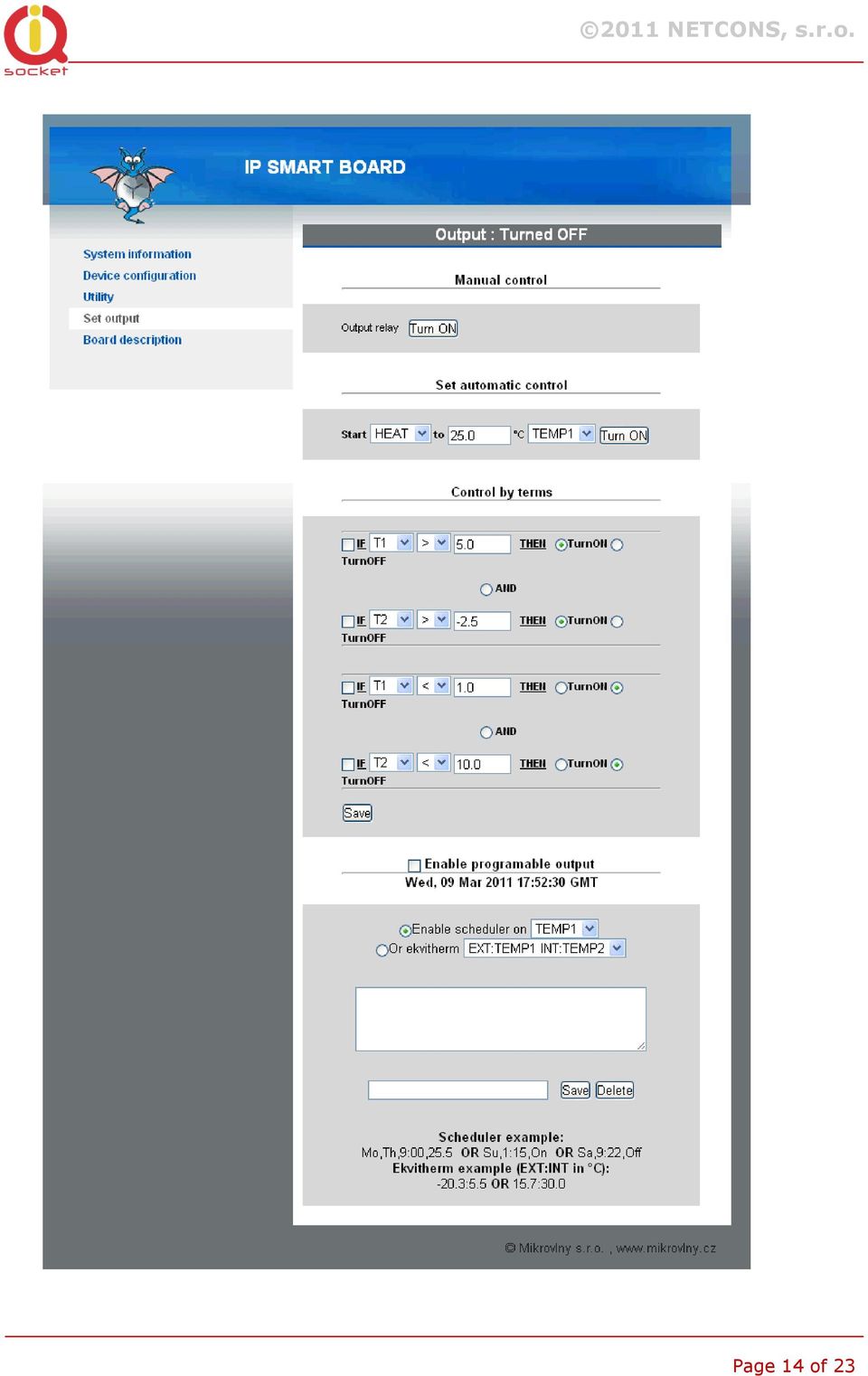
15 3.7.1 Status row Status row displays status of the output relay Manual control of output relay By clicking on the button, it is possible to change (reverse) the relay status immediately Set automatic control (simple thermostat) It provides a simple automatic thermostat function for heating or cooling process. Relay will control heating or cooling equipment to reach defined temperature. Sensor of temperature used for the thermostat function can selected between Input1 and Input1. Hysteresis is pre-set on Device configuration page, see Chapter Control by terms (advanced automatic controller) Behavior (state) of the relay depends on meeting terms in a simple program. SNMP trap can be generated instead/or among changing of the relay state. Evaluated terms, besides temperature readings at the Input1/2, can include also reading of the voltage input (Vin) and the digital input (Din). Program consists from two independent terms, allowing to include two independent inputs into the evaluation. Hysteresis defined on Device configuration page do not apply! Page 15 of 23

16 Example 1: Turn on the relay if temperature at Input1 is bellow -3.5 C and turn it off when temperature is higher than 25.0 C Example 2: Turn on the relay if temperature at Input1 is bellow -3.5 C while there is Log.1 at digital input Din and turn relay off if temperature is higher than 25.0 C while there is Log.0 at the digital input. In this case, selected sign is = and Log.1 is represented as 1.0, Log.0 as 0.0; actual threshold for changing state is about 0.5V (voltage 0.5V and higher is evaluated as Log.1). Page 16 of 23

17 Note. If particular input used in the terms is not connected to the board, particular term is not being evaluated. 3.8 Enable programmable output (Scheduled thermostat, Equithermal thermostat) It allows to perform scheduled programmable thermostat function, or Equithermal thermostat. Only one of them is possible to use at a time, can t be used simultaneously. Each setting can contain up to 30rows of definitions. Page 17 of 23

18 3.8.1 Scheduled thermostat Scheduled thermostat is working only after obtaining valid time from the NTP server. Every row represents change of target temperature at given time. Example: Keep temperature 25 C every day after 14:35, and 10.5 C after 22:00. Configurations rows will be: Mo,Tu,We,Th,Fr,Sa,Su,14:35,25.0 (click to Save) Mo,Tu,We,Th,Fr,Sa,Su,22:00,10.5 (click to Save) To delete all rows, enter ALL and then click on Delete, or enter complete or partial row to be deleted and click on Delete. All rows containing the part of row will be deleted, e.g. Mo will erase all rows containing Mo. It is possible to define change only in particular day of week, e.g. Example: Keep temperature 25 C after every Monday 00:00, and 10.5 C after every Wednesday 22:00. Mo,00:00,25.0 (click to Save) We,22:00,10.5 (click to Save) Day of week shortcuts: Mo-Monday; Tu-Tuesday; We-Wednesday; Th-Thursday; Fr-Friday; Sa- Saturday; Su-Sunday Equithermal curve Equithermal curve represents dependency of one temperature on another, e.g. internal temperature on external. IQSB-PicoIP allows to enter up to 30 points of the curve. The curve is entered in form of rows, click to Save after each row. Syntax is: -20.3:5.5 or 10.5:30.0, where first temperature is input (e.g. external) temperature, after the colon, is output (target) temperature to be maintained (e.g. internal) in particular place. Values between definition points are calculated by linear extrapolation (values below minimum and above maximum are not extrapolated) To delete definition, enter ALL and click to Delete, or enter text contained by the row to be deleted. 4 Important status messages Page 18 of 23

19 Embedded WEBui interface can display several status messages, let s focus to most important ones only: Message displayed after clicking to Save button. New values are already written in permanent Flash memory and will be taken into account after device is restarted. Warning message informing that an automatic mode has been set successfully, but user has manually changed state of the relay. Relay status will be returned into state per particular automatic mode activated in Set output menu. Warning message informing than another automatic mode is already active; e.g. attempt to simultaneously activate Scheduler and Control by terms, which can cause colliding changes of the output relay state. 5 Use of the Pushbutton Press the push button shortly to toggle the relay state between On and Off. To revert back factory default configuration, push the button for longer than 4 seconds. Release it, and all LED indicators will start blinking. Press push button shortly during following 10 seconds to confirm the reset of configuration. 6 Software 6.1 Use of utility Mlocator.exe Mlolcator.exe is utility allowing to quickly search for presence of IQSB-PicoIP in Ethernet network, to determine and change of device s IP address and to upgrade device s firmware, running on Windows platform. Page 19 of 23


20 After clicking Scan button, searching for presence is preformed and list of found devices is shown in the main program window. Clicking to Set IP addresses allows to temporary change IP address in order to enable configuration via WEBui. Page 20 of 23


21 6.2 Obtaining values via SNMP protocol using ireasoning MIB browser As mentioned before, IQSB-PicoIP can be used among virtually any software supporting SNMP 1.0 protocol. Ireasoning MIB Browser is a powerful, yet freeware utility, equipped with also SNMP trap receiver capability besides MIB browser. After configuring relevant settings such as IP address and SNMP communities of the IQSB-PicoIP, Ireasoning MIB Browser can read values of all inputs or to control the relay output over IP network. 7 Technical specification Model Power supply Output Inputs IQsocket IQSB-PicoIP 12V DC ±20%, via Power Jack, PoE or terminal block Relay, 30v DC, 2A max (for resistive load) 2x Temperature inputs, for DS18B20 1-wire sensor 1x On board temperature sensor 1x Analog voltage sensing 0-3V DC Page 21 of 23
22 Network interface Protocols Security 1x Digital input, 0 to 30V DC, threshold 1V for Log.1 RJ45, 10M Ethernet HTTP for WEBui SNMP 1.0 Username/password for WEBui Read/Write communities for SNMP Indicators Features Dimensions Weight RJ45 embedded LEDs: Power and LINK/ACT Sensors activity: yellow LED RELAY: red LED Reading of current values of all inputs via SNMP and WEBui Manual control of relay via SNMP, WEBui and by push button Provides min/max values of temperature over SNMP and WEBui Simple automatic thermostat Advanced automatic controller based on terms evaluating state of up to two selected inputs Programmable scheduled thermostat Equithermal thermostat 64x46mm 0.1kg netto Operating temperature 0 to +50 C Humidity Operating temperature 0 to +50 C Mounting Compliance Max. 80%, non-condensing Naked PC board to be mounted in customer s housing CE 7.1 Operation, maintenance and safety recommendations Do not modify product in any way and do not operate product modified any way. Warranty is void when product was disassembled or modified in any way. Product is not fused; ensure it is installed in fused electric installation only. Product can be operated only indoor office/house environment. Do not expose it to humid, wet nor chemically aggressive environment. Product is not designed for industrial operation with aggressive environment. Don t expose product to vibrations, shaking or fall downs to avoid product damage. Load current 30V/2A DC is valid for resistive load. If you need to switch an non-resistive or higher current load, use an external relay/contactor rated Page 22 of 23


23 for target load among the product. Switching a non-resistive load or higher than nominal rating currents can cause permanent damage of switching elements, which is not covered by warranty. WARNING: This product is not designed for use in, and should not be used for, medical applications. 8 Ordering and accessories IQsocket product family uses following ordering code system: IQSx-y-z Example:IQSB-PicoIP Product family: W=WALL R=RACK D=DIN B=Board Product model: GSM IP RS232 HDO IPGSM PicoIP Output Socket type: F=Schuko E=French Optional accessories Code ST-TMP-02 Description Temperature sensor with metal housing, 1m cable SR-TMP-02 Page 23 of 23
HWg-STE HWg-STE PoE MANUAL
 HWg-STE HWg-STE PoE MANUAL www.hw-group.com Page 2 HWg-STE connectors LED indicators Green: Power & Mode Yellow: Link & Activity SENSORS S1 and S2 ports for connecting temperature or humidity sensors.
LAN CONTROLLER instruction from 2.30
 LAN CONTROLLER instruction from 2.30 RESTARTER, MONITOR, WATCHDOG, CONTROLLER FEATURES: WWW or SNMP v2 management. firmware upgrade via TFTP read data in real time without refresh page read all sensors
Manual. IP Sensor and Watchdog IPSW2210. I P S W 2 2 1 0 M a n u a l P a g e 1. Relay Output. Power input. 12VDC adapter LED Indicators. 2 Dry.
 IP Sensor and Watchdog IPSW2210 Manual Relay Output Power input 12VDC adapter LED Indicators 1 wire 2 Dry Output Green : Power Yellow: Link temperature & humidity contact inputs LED indicator sensor input
Users manual. TCW181B-CM_R1 Page 1
 Ethernet controller TCW181B-CM Users manual 1. Short description TCW181B-CM is 8-channel Ethernet relay board, which is designed to work in IP-based networks and managed by WEB interface or SNMP programs.
Innovative Electronics for a Changing World INDEX
 Innovative Electronics for a Changing World INDEX 1. SYSTEM DESCRIPTION 2. BOARD CONNECTIONS terminals and indicators 3. CONNECTION DIAGRAM 4. START UP GUIDE and passwords 5. HOME PAGE 6. STATUS PAGE 7.
Poseidon2 3268 MANUAL
 Poseidon2 3268 MANUAL Safety information The device complies with regulations and industrial standards in force in the Czech Republic and the European Union. The device has been tested and is supplied
USER MANUAL. PingBrother EPIW104 managed passive poe switch & IP watchdog
 USER MANUAL PingBrother EPIW104 managed passive poe switch & IP watchdog CONTENT Content... 2 Chapter 1... 3 1.1 Preface... 3 1.2 CE mark warning... 3 1.3 FCC warning... 4 Chapter 2... 5 2.1 Physical description...
1 Serial RS232 to Ethernet Adapter Installation Guide
 Installation Guide 10/100 Mbps LED (amber color ) Link/Activity LED (green color ) 1. Introduction Thank you for purchasing this 1-port RS232 to Ethernet Adapter (hereinafter referred to as Adapter ).
Expert Power Control NET 4x 8212 / 8213
 2010 Gude Analog- und Digitalsysteme GmbH 2010 Gude Analog- und Digitalsysteme GmbH 23.08.2010 Content 3 Table of content Kapitel 1 Security Advise 5 Kapitel 2 Description 5 Kapitel 3 Hardware 6 3.1 Content
Ethernet controller TCW122B-CM (Firmware version 2.xx) User manual
 User manual") Ethernet controller TCW122B-CM (Firmware version 2.xx) User manual 1. Short description TCW122B-CM is an Ethernet controller, based on TCW122 hardware. It has 2 digital and 2 analog inputs, 1-Wire interface
Ethernet controller TCW122B-CM (Firmware version 2.xx) User manual 1. Short description TCW122B-CM is an Ethernet controller, based on TCW122 hardware. It has 2 digital and 2 analog inputs, 1-Wire interface
Power Supply SNMP Interface User Manual for SRL versions
 Power Supply SNMP Interface User Manual for SRL versions SNMP-L User Manual 150722(firmware 02r_a12).doc Table of Contents 1. INTRODUCTION... 3 1.1 Default IP Address... 3 2. LOGIN... 4 3. MONITORING &
Quick Installation Guide
 0, Total 18 Quick Installation Guide Sep, 2013 1, Total 18 Thank you for purchasing Enterprise High Gain Outdoor CPE. This manual will instruct you how to configure and manage this CPE, enable you to use
SNMP Web card. User s Manual. Management Software for Uninterruptible Power Supply Systems
 SNMP Web card User s Manual Management Software for Uninterruptible Power Supply Systems Table of Contents 1. Overview... 3 1.1 Introduction... 3 1.2 Features... 3 1.3 Overlook... 3 1.4 Installation and
3.5 EXTERNAL NETWORK HDD. User s Manual
 3.5 EXTERNAL NETWORK HDD User s Manual Table of Content Before You Use Key Features H/W Installation Illustration of Product LED Definition NETWORK HDD Assembly Setup the Network HDD Home Disk Utility
Recommended Tools and Supplies: Small Flat Blade Screwdriver, 35mm x 7.5mm DIN Rail. Qwik Install
 TPDIN-Monitor-WEB Web Based Monitor and Control Remote Power Stations Backup Power Systems Solar Systems Wind Powered Systems Industrial Sense & Control Process Automation Congratulations! on your purchase
NetProbe Lite. Web Based 8 Channel Sensor Collector. User Manual. Version 1.2
 NetProbe Lite Web Based 8 Channel Sensor Collector User Manual Version 1.2 Copyright Information Copyright 2004-2005, Mega System Technologies, Inc. All rights reserved. Reproduction without permission
3.5 Mobile LAN Disk. User Guide
 3.5 Mobile LAN Disk User Guide Contents 1. Hardware...2 1.1 Power...2 1.2 Ports...2 1.3 Reset Button...2 1.4 LEDs...2 1.5 Front View...3 1.6 Rear View...3 2. Installation....... 4 2.1 Requirements 4 2.2
Starting Guide - Poseidon 3265 First steps for remote monitoring with Poseidon & GSM
 Poseidon 3265 starting guide Poseidon 3265 Starting Guide - Poseidon 3265 First steps for remote monitoring with Poseidon & GSM 1) Connecting Poseidon 3265 1.1) Check DIP switches settings. For installation
SMS Alarm Messenger. Setup Software Guide. SMSPro_Setup. Revision 090210 [Version 2.2]
![SMS Alarm Messenger. Setup Software Guide. SMSPro_Setup. Revision 090210 [Version 2.2]](/thumbs/29/13662687.jpg "SMS Alarm Messenger. Setup Software Guide. SMSPro_Setup. Revision 090210 [Version 2.2]") SMS Alarm Messenger SMSPro_Setup Revision 090210 [Version 2.2] ~ 1 ~ Contents 1. How to setup SMS Alarm Messenger?... 3 2. Install the SMSPro_Setup software... 5 3. Connection Type... 6 4. Connection Port
SMS Alarm Messenger SMSPro_Setup Revision 090210 [Version 2.2] ~ 1 ~ Contents 1. How to setup SMS Alarm Messenger?... 3 2. Install the SMSPro_Setup software... 5 3. Connection Type... 6 4. Connection Port
SNMP Web Management. User s Manual For SNMP Web Card/Box
 SNMP Web Management User s Manual For SNMP Web Card/Box Management Software for Off-Grid Inverter Version: 1.2 Table of Contents 1. Overview... 1 1.1 Introduction... 1 1.2 Features... 1 1.3 Overlook...
Product Guide CM-Relay
 Product Guide CM-Relay www.theclimate.co.uk tel: 01491 410913 The Climate, Badgers Bank, Harpsden, Henley-on-Thames, Oxfordshire RG9 4HL. Overview CM-Relay combines climate monitoring with remote relay
Chapter 4 Management. Viewing the Activity Log
 Chapter 4 Management This chapter describes how to use the management features of your NETGEAR WG102 ProSafe 802.11g Wireless Access Point. To get to these features, connect to the WG102 as described in
Hardware Installation Guide HotPoint 5100 Access Point
 HotPoint Hardware Installation Guide HotPoint 5100 Access Point Published March 2014 (Revised 2015) 2014 Firetide, Inc. All rights reserved. Firetide, the Firetide logo, Reliable connectivity anywhere,
Remote Monitoring Unit SC8100. Monitoring Unit SC8100
 Monitoring Unit SC8100 Remote Monitoring Unit SC8100 Environmental monitoring of any facilities, control of security breaches, temperatures, smoke, water leakages, voltages and more. Compatible with all
TDP43ME NetPS. Network Printer Server. Control Center. for Ethernet Module
 Panduit Corp. 2010 TDP43ME NetPS PA26306A01 Rev. 01 11-2010 Network Printer Server Control Center for Ethernet Module NOTE: In the interest of higher quality and value, Panduit products are continually
The GV-I/O Box 8 Ports provides 8 inputs and 8 relay outputs, and supports both DC and AC output voltages.
 GV-I/O Box 8 Ports The GV-I/O Box 8 Ports provides 8 inputs and 8 relay outputs, and supports both DC and AC output voltages. Key Features 8 inputs and 8 outputs are provided. Up to 9 pieces of GV-I/O
TCP/IP MODULE CA-ETHR-A INSTALLATION MANUAL
 TCP/IP MODULE CA-ETHR-A INSTALLATION MANUAL w w w. c d v g r o u p. c o m CA-ETHR-A: TCP/IP Module Installation Manual Page Table of Contents Introduction...5 Hardware Components... 6 Technical Specifications...
LAN Controller V2.0 Firmware version 3.00
 LAN Controller V2.0 Firmware version 3.00 Manual LAN Controller LAN controller is a simple, but innovative device which has long been lacking in the market network solutions. A small board serves as a
JNIOR. Overview. Get Connected. Get Results. JNIOR Model 310. JNIOR Model 312. JNIOR Model 314. JNIOR Model 410
 The INTEG is an Ethernet I/O (digital, analog) device that monitors and controls a small set of process signals. functions as both basic I/O for integration with another application or system AND as a
Network Power Manager. User Manual
 Network Power Manager User Manual Table of Contents 1. Introduction... 1 2. PDU Package... 2 3. Function... 3 4. Installation... 4 5. Web Interface... 5 1. Introduction The PDU is an Internet ready device
The GV-I/O Box 16 Ports provides 16 inputs and 16 relay outputs, and supports both DC and AC output voltages.
 GV-I/O Box 16 Ports The GV-I/O Box 16 Ports provides 16 inputs and 16 relay outputs, and supports both DC and AC output voltages. Key Features 16 inputs and 16 outputs are provided. Up to 9 pieces of GV-I/O
CYAN SECURE WEB APPLIANCE. User interface manual
 CYAN SECURE WEB APPLIANCE User interface manual Jun. 13, 2008 Applies to: CYAN Secure Web 1.4 and above Contents 1 Log in...3 2 Status...3 2.1 Status / System...3 2.2 Status / Network...4 Status / Network
Wifi Pan/Tilt IP Camera User Manual
 Wifi Pan/Tilt IP Camera User Manual Rev. 3.0 Software Version 3.00 May. 25 th.2009 Table of Contents 1. PRODUCT VIEWS...3 1.1. PRONT PANEL...3 1.2. BACK PANEL...3 1.3. ACCESSORIES...4 2. SETUP AND STARTUP...5
Table of Contents. 1. Introduction...1. 2. PDU Package...2. 3. Function...3. 4. Installation...5. 5. Web Interface...7
 PDU User Manual Table of Contents 1. Introduction...1 2. PDU Package...2 3. Function...3 4. Installation...5 5. Web Interface...7 1. Introduction The PDU is an Internet ready device designed and is equipped
Honeywell Internet Connection Module
 Honeywell Internet Connection Module Setup Guide Version 1.0 - Page 1 of 18 - ICM Setup Guide Technical Support Setup - Guide Table of Contents Introduction... 3 Network Setup and Configuration... 4 Setting
SETUP GUIDE SNMP ALARM ADAPTOR COMPATIBLE WITH SIGMA, RADIAN, TPCMQ, auro-he & BLUEstreak POWER SHELVES
 SNMP ALARM ADAPTOR COMPATIBLE WITH SIGMA, RADIAN, TPCMQ, auro-he & BLUEstreak POWER SHELVES www.unipowerco.com 2014 UNIPOWER LLC All Rights Reserved NORTH AMERICA 3900 Coral Ridge Drive, Coral Springs,
User Manual. EtherUSB
 User Manual EtherUSB USB Ethernet Access Point for PDA V 2.0 Clarinet Systems, Inc. Clarinet Systems, Inc. http://www.clarinetsys.com Page 1 Publication Revision No. Control Table Rev. No. Date Contents
GPS NTP Time Server for Intranet Networks DIN RAIL Version
 GPS NTP Time Server for Intranet Networks DIN RAIL Version Description: GPS NTP time server is very simple low cost solution for Ethernet / Intranet time synchronization. Each computer or devices with
LS1024B / LS2024B/ LS3024B. Solar Charge Controller USER MANUAL
 EPSOLAR LS1024B / LS2024B/ LS3024B Solar Charge Controller USER MANUAL Thank you very much for selecting our product! This manual offers important information and suggestions with respect to installation,
securityprobe 5E Standard
 securityprobe 5E Standard securityprobe 5E Standard Monitor the physical environment and receive alerts of any disturbances, such as unauthorized intruders, security breaches, high temperatures, smoke,
ENET-710. ENET-710 - Ethernet Module ENET-710 JAN / 06 FOUNDATION
 ENET-710 ENET-710 - Ethernet Module JAN / 06 ENET-710 FOUNDATION E N E T 7 1 0 ME smar www.smar.com Specifications and information are subject to change without notice. Up-to-date address information is
Chapter 3 Management. Remote Management
 Chapter 3 Management This chapter describes how to use the management features of your ProSafe 802.11a/g Dual Band Wireless Access Point WAG102. To access these features, connect to the WAG102 as described
EM6230 e-camview HD outdoor IP camera
 EM6230 e-camview HD outdoor IP camera 2 ENGLISH EM6230 e-camview HD outdoor IP camera Table of contents 1.0 Introduction... 3 1.1 Packing contents... 3 1.2 Requirements to access the camera.... 3 1.3 Major
Emerson Smart Firewall
 DeltaV TM Distributed Control System Product Data Sheet Emerson Smart Firewall The Emerson Smart Firewall protects the DeltaV system with an easy to use perimeter defense solution. Purpose built for easy
User s Manual Network Management Card
 User s Manual Network Management Card RMCARD202 Intelligent Network Management Card allows a UPS system to be managed, monitored, and configured Version 1.0 E-K01-SNMP005-0 TABLE OF CONTENTS Introduction
- 1 - SmartStor Cloud Web Admin Manual
 - 1 - SmartStor Cloud Web Admin Manual Administrator Full language manuals are available in product disc or website. The SmartStor Cloud Administrator web site is used to control, setup, monitor, and manage
MICROSENS. Installation Switch with PoE (5x10/100Base-TX) and fiber uplink (1x100Base-FX) General. Features
 and fiber uplink (1x100Base-FX) General. Features") Installation Switch with PoE (5x10/100Base-TX) and fiber uplink (1x100Base-FX) MICROSENS General The MICROSENS Installation Switch enables the connection of 5 end devices via twisted pair cable which also
Installation Switch with PoE (5x10/100Base-TX) and fiber uplink (1x100Base-FX) MICROSENS General The MICROSENS Installation Switch enables the connection of 5 end devices via twisted pair cable which also
LAN Controller V2.0 Firmware version 3.10
 LAN Controller V2.0 Firmware version 3.10 Manual LAN Controller LAN controller is a simple, but innovative device which has long been lacking in the market network solutions. A small board serves as a
securityprobe5es -X20
 securityprobe5es -X20 v.100.00x securityprobe5es -X20 will monitor the physical environment and alert you of any disturbances, such as unauthorized intruders, security breaches, high temperatures, smoke,
WLAN Outdoor CPE For 2.4G. Quick Installation Guide
 WLAN Outdoor CPE For 2.4G Quick Installation Guide Part I: External Installation Direction A. Check the parts in your box CPE SET 1 DC 12V/1.5A Power Adapter 1 PoE DC Injector 1 Hose Clamps 2 Manual &
BiPAC 7404V series. VoIP/(802.11g) ADSL2+ (VPN) Firewall Router. Quick Start Guide
 ADSL2+ (VPN) Firewall Router. Quick Start Guide") BiPAC 7404V series VoIP/(802.11g) ADSL2+ (VPN) Firewall Router Quick Start Guide VoIP/(802.11g) ADSL2+ (VPN) Firewall Router For more detailed instructions on configuring and using the Billion VoIP/(802.11g)
BiPAC 7404V series VoIP/(802.11g) ADSL2+ (VPN) Firewall Router Quick Start Guide VoIP/(802.11g) ADSL2+ (VPN) Firewall Router For more detailed instructions on configuring and using the Billion VoIP/(802.11g)
DVG-2101SP VoIP Telephone Adapter
 This product can be set up using any current web browser, i.e., Internet Explorer 6 or Netscape Navigator 6.2.3. DVG-2101SP VoIP Telephone Adapter Before You Begin 1. If you purchased this VoIP Telephone
IP Box Camera ACM-5711. Ver. 081016. Hardware User s Manual
 IP Box Camera ACM-5711 Ver. 081016 Hardware User s Manual 0 0 PRECAUTIONS 1. Read these instructions All the safety and operating instructions should be read before the product is operated. 2. Heed all
Ultra Thin Client TC-401 TC-402. Users s Guide
 Ultra Thin Client TC-401 TC-402 Users s Guide CONTENT 1. OVERVIEW... 3 1.1 HARDWARE SPECIFICATION... 3 1.2 SOFTWARE OVERVIEW... 4 1.3 HARDWARE OVERVIEW...5 1.4 NETWORK CONNECTION... 7 2. INSTALLING THE
Wireless Router Setup Manual
 Wireless Router Setup Manual NETGEAR, Inc. 4500 Great America Parkway Santa Clara, CA 95054 USA 208-10082-02 2006-04 2006 by NETGEAR, Inc. All rights reserved. Trademarks NETGEAR is a trademark of Netgear,
Product Description... 1 Internal Management Features... 3 Front Panel... 5 Watchdog Features... 7
 Contents Introduction--1 Product Description.................................. 1 Internal Management Features........................... 3 Front Panel........................................ 5 Watchdog
SNMP-1000 Intelligent SNMP/HTTP System Manager Features Introduction Web-enabled, No Driver Needed Powerful yet Easy to Use
 SNMP-1000 Intelligent SNMP/HTTP System Manager Features Monitors system fans, temperature, voltage, power supply, CPU fan, CPU temperature, Vcore, watchdog timer etc. Stand alone system monitoring, no
BIT COMMANDER. Serial RS232 / RS485 to Ethernet Converter
 BIT COMMANDER Serial RS232 / RS485 to Ethernet Converter (Part US2000A) Copyrights U.S. Converters 1 Contents Overview and Features... 3 Functions..5 TCP Server Mode... 5 Httpd Client Mode.5 TCP Auto mode....6
AC-115 Compact Networked Single Door Controller. Installation and User Manual
 AC-115 Compact Networked Single Controller Installation and User Manual December 2007 Table of Contents Table of Contents 1. Introduction...5 1.1 Key Features... 6 1.2 Technical Specifications... 7 2.
xepi 2 Installation Guide Diagnostic Unit and Configuration Interface Doc. Version 4.0 English
 xepi 2 Diagnostic Unit and Configuration Interface Doc. Version 4.0 Installation Guide English Dear Customer, This "Installation Guide" will help you to install the hardware. If you have any further questions,
DOORKING SYSTEMS 1830 SERIES NETWORK WORKSHOP LAN APPLICATIONS ACCESS CONTROL SOLUTIONS LOCAL AREA NETWORK (LAN) CONNECTION REV 04.
 CONNECTION REV 04.") DOORKING SYSTEMS ACCESS CONTROL SOLUTIONS 1830 SERIES NETWORK WORKSHOP LAN APPLICATIONS REV 04.11 LOCAL AREA NETWORK (LAN) CONNECTION Ethernet Connection: An Ethernet Cable, or wireless connection must
DOORKING SYSTEMS ACCESS CONTROL SOLUTIONS 1830 SERIES NETWORK WORKSHOP LAN APPLICATIONS REV 04.11 LOCAL AREA NETWORK (LAN) CONNECTION Ethernet Connection: An Ethernet Cable, or wireless connection must
Firewall VPN Router. Quick Installation Guide M73-APO09-380
 Firewall VPN Router Quick Installation Guide M73-APO09-380 Firewall VPN Router Overview The Firewall VPN Router provides three 10/100Mbit Ethernet network interface ports which are the Internal/LAN, External/WAN,
User s Manual UPS SERIES. Network Interface Card UPS-IPCARD. I-00453 Rev B
 User s Manual UPS SERIES Network Interface Card UPS-IPCARD I-00453 Rev B TABLE OF CONTENTS INTRODUCTION............................................................. 3-4 INSTALLATION GUIDE.......................................................
NeoGate TG Series Installation Guide
 NeoGate TG Series Installation Guide Version: V1.1 Yeastar Technology Co., Ltd. Date: Sept. 2, 2014 http://www.yeastar.com 1/14 Contents NeoGate TG Series Installation Guide 1. Preparation before Installation...
INSTALLATION/PROGRAMMING INSTRUCTIONS E4KP ENTRYCHECK
 Security Door Controls 3580 Willow Lane, Westlake Village, CA 91361-4921 (805) 494-0622 Fax: (805) 494-8861 www.sdcsecurity.com E-mail: [email protected] INSTALLATION/PROGRAMMING INSTRUCTIONS E4KP
BiPAC 7800NL. Wireless-N ADSL2+ Firewall Router. Quick Start Guide
 BiPAC 7800NL Wireless-N ADSL2+ Firewall Router Quick Start Guide BiPAC 7800NL Wireless-N ADSL2+ Firewall Router Billion BiPAC 7800NL Wireless-N ADSL2+ Firewall Router PLEASE READ THE QUICK START GUIDE
WIZ-Embedded WebServer User s Manual (Ver. 1.0)
") [텍스트 입력] WIZ-Embedded WebServer User s Manual (Ver. 1.0) 2007 WIZnet Inc. All Rights Reserved. For more information, visit our website at www.wiznet.co.kr Document History Information Revision Data Description
[텍스트 입력] WIZ-Embedded WebServer User s Manual (Ver. 1.0) 2007 WIZnet Inc. All Rights Reserved. For more information, visit our website at www.wiznet.co.kr Document History Information Revision Data Description
Universal network-enabled automation interface for home automation, commercial control, and monitoring applications
 BARIONET Universal network-enabled automation interface for home automation, commercial control, and monitoring applications This Manual Describes: Barionet 100 (Original Barionet) Firmware Version: 3.02
Installation Guide. Wireless N Access Point EAP110/EAP120/EAP220
 Installation Guide Wireless N Access Point EAP110/EAP120/EAP220 CONTENTS Network Topology 01 Hardware Overview 02 Hardware Installation 05 1. Installation Requirements... 05 2. Mounting Bracket... 05
* DISCLAIMER: Contents. How to Use This Guide: COMMERCIAL INSTALL GUIDE 2
 COMMERCIAL INSTALL GUIDE 2 Contents How to Use This Guide: The first section of this guide is designed to assist you with the installation of your DECK Monitoring hardware. The revenue grade meter and
Ethernet. Customer Provided Equipment Configuring the Ethernet port.
 Installing the RDSP-3000A-NIST Master Clock. Ethernet Connect the RJ-45 connector to a TCP/IP network. Equipment The following equipment comes with the clock system: RDSP-3000A-NIST Master Clock Module.
Chapter 6 Using Network Monitoring Tools
 Chapter 6 Using Network Monitoring Tools This chapter describes how to use the maintenance features of your Wireless-G Router Model WGR614v9. You can access these features by selecting the items under
C24-CAMANL Video Server/Encoder
 C24-CAMANL Video Server/Encoder User s Guide Table of Contents CHAPTER 1 INTRODUCTION... 1 Overview... 1 Physical Details - Video Server... 2 Package Contents... 3 CHAPTER 2 BASIC SETUP... 4 System Requirements...
Load Balance Router R258V
 Load Balance Router R258V Specification Hardware Interface WAN - 5 * 10/100M bps Ethernet LAN - 8 * 10/100M bps Switch Reset Switch LED Indicator Power - Push to load factory default value or back to latest
Step by Step Guide for Upgrading Your NetCamPro Camera to Cloud Mode Using an Android Device
 Step by Step Guide for Upgrading Your NetCamPro Camera to Cloud Mode Using an Android Device Table of Contents Introduction...2 Backing Out Cloud Mode...2 Indoor Camera Factory Reset...2 Outdoor Camera
Multi-Homing Dual WAN Firewall Router
 Multi-Homing Dual WAN Firewall Router Quick Installation Guide M73-APO09-400 Multi-Homing Dual WAN Firewall Router Overview The Multi-Homing Dual WAN Firewall Router provides three 10/100Mbit Ethernet
Firmware version: 1.10 Issue: 7 AUTODIALER GD30.2. Instruction Manual
 Firmware version: 1.10 Issue: 7 AUTODIALER GD30.2 Instruction Manual Firmware version: 2.0.1 Issue: 0.6 Version of the GPRS transmitters configurator: 1.3.6.3 Date of issue: 07.03.2012 TABLE OF CONTENTS
HD Megapixel Indoor Network Camera Quick Start Guide
 HD Megapixel Indoor Network Camera Quick Start Guide Version 1.0.0 Welcome Thank you for purchasing our network camera! This quick start guide is designed to be a reference tool for your system. Please
ModBus Server - KNX. Gateway for integration of KNX equipment into Modbus (RTU and TCP) control systems.
 control systems.") IntesisBox ModBus Server - KNX Gateway for integration of KNX equipment into Modbus (RTU and TCP) control systems. Integrate KNX based lighting control into your SCADA, BMS, PLC "talking" Modbus. Master
IntesisBox ModBus Server - KNX Gateway for integration of KNX equipment into Modbus (RTU and TCP) control systems. Integrate KNX based lighting control into your SCADA, BMS, PLC "talking" Modbus. Master
5-port / 8-port 10/100BaseTX Industrial Ethernet Switch User Manual
 5-port / 8-port 10/100BaseTX Industrial Ethernet Switch User Manual Content Overview... 1 Introduction... 1 Features... 3 Packing List... 4 Safety Precaution... 4 Hardware Description... 5 Front Panel...
VoIP Zone Controller: 4-Port Audio Out Operations Guide
 The IP Endpoint Company VoIP Zone Controller: 4-Port Audio Out Operations Guide SiP Compliant 010881 Document Part #930109D for Firmware Version 1.0.6 CyberData Corporation 3 Justin Court Monterey, CA
Quick Installation Guide. Live! Titanium
 Quick Installation Guide Live! Titanium Contents 1. Live! overview... 2. Installation... 3. Network setup... 4. Wireless setup... 5. Configuring your Live!... 6. Troubleshooting... 2 4 7 8 9 10 1 1. Live!
Welcome. Unleash Your Phone
 User Manual Welcome Unleash Your Phone For assistance with installation or troubleshooting common problems, please refer to this User Manual or Quick Installation Guide. Please visit www.vonage.com/vta
3.5 LAN HDD Enclosure User s Manual
 3.5 LAN HDD Enclosure User s Manual NOTE: 1. USB and LAN can t be used at the same time. 2. HDD should be formatted as FAT32. Please check Disk utility section in this manual. 3. For internet FTP usage,
PRONET WEB SERVER. INSTRUCTIONS FOR INSTALLATION AND USE English. Version 01/15 Ident no. 50950129
 PRONET WEB SERVER INSTRUCTIONS FOR INSTALLATION AND USE English EN Version 01/15 Ident no. 50950129 Table of Contents 1. About these instructions 3 2. Important information for your safety 4 2.1. Intended
User Manual. EtherUSB
 User Manual EtherUSB USB Ethernet Access Point for PDA V 1.6 Page 1 Publication Revision No. Control Table Rev. No. Date Contents 1.6 8/22/07 Support connection of multiple WM5.0 devices 1.5 6/18/07 Support
IP Camera (L series) User manual 2013-05 V1.1
 User manual 2013-05 V1.1") Dear users, the configuration for this camera is professional, so please read the user manual carefully before using the camera. IP Camera (L series) User manual 2013-05 V1.1 Statement If the user manual
Dear users, the configuration for this camera is professional, so please read the user manual carefully before using the camera. IP Camera (L series) User manual 2013-05 V1.1 Statement If the user manual
Management Software. Web Browser User s Guide AT-S106. For the AT-GS950/48 Gigabit Ethernet Smart Switch. Version 1.0.0. 613-001339 Rev.
 Management Software AT-S106 Web Browser User s Guide For the AT-GS950/48 Gigabit Ethernet Smart Switch Version 1.0.0 613-001339 Rev. A Copyright 2010 Allied Telesis, Inc. All rights reserved. No part of
PE6108/PE6208/PE8108/PE8208
 Energy Intelligence Solutions PE6108/PE6208/PE8108/PE8208 eco PDU Distribution Unit ATEN has developed a new generation of green energy power distribution units (PDUs) to effectively increase the efficiency
Turn on all of your network devices and then check to see if the LEDs on the Access Point display normally as the diagram below describes.
 Connect to the Access Point with the Ethernet cable or via wireless. The default SSID of the Access Point is TP-LINK_ XXXXXX. The XXXXXX is the last 6 characters of the Access Point s MAC address. Plug
Temperature Alert. LAN-based Temperature and Humidity Data Logger
 Temperature Alert LAN-based Temperature and Humidity Data Logger LAN-based Temperature and Humidity Monitoring - Supports Simultaneous WiFi and Hardwired Interfaces -20 C to +60 C (-4 F to +140 F) Standard
IntesisBox KNX Modbus TCP master
 IntesisBox KNX TCP master Gateway for integration of TCP slave devices into KNX control systems. Integrate any TCP slave device into KNX. KNX TCP slave EIB Bus IntesisBox Ethernet slave LinkBoxEIB Configuration
NeoGate TA Series Quick Installation Guide
 NeoGate TA Series Quick Installation Guide Version: V1.1 Yeastar Technology Co., Ltd. Date: November 18, 2014 http://www.yeastar.com 1/15 Contents NeoGate TA Series Quick Installation Guide 1. Preparation
Single-bay NAS Server
 Single-bay NAS Server NAS-1100 User s Manual Copyright (C) 2004 PLANET Technology Corp. All rights reserved. The products and programs described in this User s Manual are licensed products of PLANET Technology,
Amcrest 960H DVR Quick Start Guide
 Amcrest 960H DVR Quick Start Guide Welcome Thank you for purchasing our Amcrest 960H DVR! This quick start guide will help you become familiar with our DVR in a very short time. Before installation and
IP Power Stone 4000 User Manual
 IP Power Stone 4000 User Manual Two Outlet Remote AC Power Controller Multi Link, Inc. 122 Dewey Drive Nicholasville, KY 40356 USA Sales and Tech Support 800.535.4651 FAX 859.885.6619 techsupport@multi
Overview. 1. GPS data tracking via GSM SMS / GPRS. 2. GPS data logging in internal memory. 3. Alarm alert via GSM SMS / Dialing / GPRS
 Vehicle or Personal Position Tracking Vehicle Status and Speed Tracking Auto Accident Report Global Position System (GPS) Navigation System Anti theft Alarm System Overview 1. GPS data tracking via GSM
Application & Quick-Start Guide
 Model: CRMWIC Web Intelligent Controller 1 This document will illustrate various ways to connect and use a CRM-WIC as well as programming examples. When connecting CRM-WIC, the installer has several interface