Product Inspection Guide
|
|
|
- Prudence Lewis
- 10 years ago
- Views:
Transcription
1 Product Inspection Guide Harness Lanyards - Shock Absorbing Rope Web Wire Rope Shock Absorbers Synthetic Rope - Twisted Rope Braided Rope Kernmantel Rope Polysteel Wire Rope Lifelines Fall Limiters - Retractable Lanyard Self Retracting Lifeline 58-64

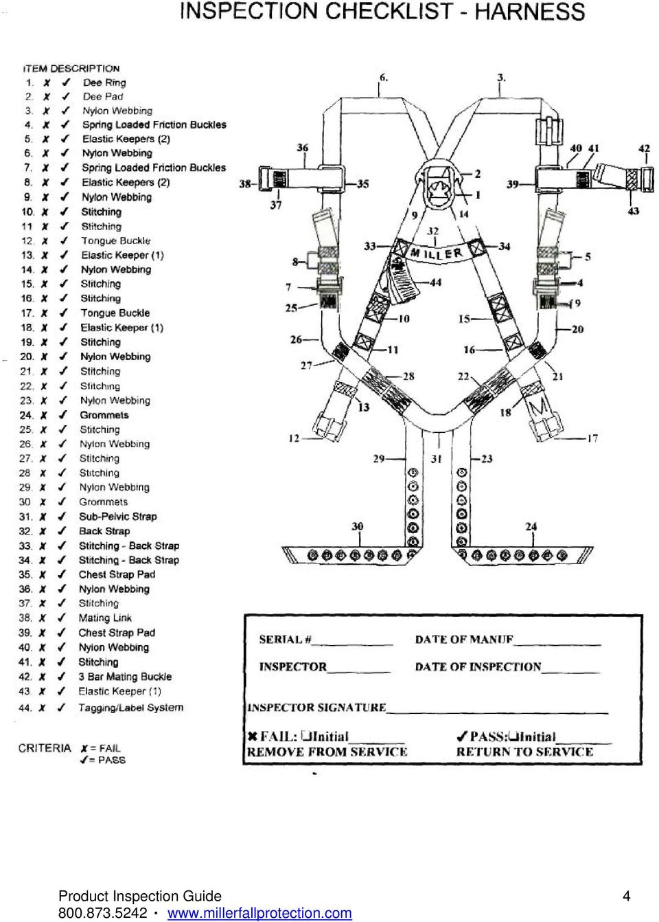
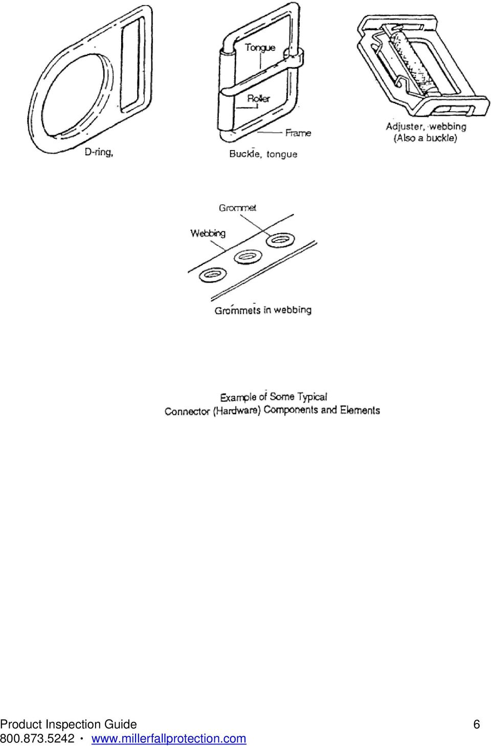
2 Harness Inspection Guidelines Webbing Grasp the webbing with your hands and bend the webbing, checking both sides. This creates surface tension making damaged fibers or cuts easier to see. Webbing damage may not show up through a sight (visual) inspection only manual (touch) the harness is equally important. Visual and Touch Inspection Cuts, nicks or tears Broken fibers/cracks Overall deterioration Modifications by user Fraying/Abrasions Discoloration of material Hard or shiny spots Webbing thickness uneven Mildew Missing Straps Undue Stretching Burnt, charred or melted fibers Dependant on cause of discoloration Indicates heat damage Indicates possible fall Clean harness Indicates possible fall Indicates heat damage Material marked w/permanent marker Check w/manufacturer Excessive hardness or brittleness Indicates heat or uv damage Stitching Visual and Touch Inspection Pulled stitches Stitching that is missing Hard or shiny spots Cut stitches Discoloration of stitching Indicates heat damage Dependant on cause of discoloration Hardware Visual and Touch Inspection Distortion (twists, bends) Rough or sharp edges Rust or corrosion Cracks or breaks Broken/distorted grommets Modification by users (ie additional holes) Tongue buckle should overlap the buckle frame and move freely back and forth in their socket Roller of tongue buckle should turn freely on frame Bars must be straight All springs must be in working condition 1

3 Harness Tagging System Every harness must have a legible tag identifying the harness, model, date of manufacture, name of manufacturer, limitations and warnings. Check tag for date of manufacture and remove from service if past adopted service life policy If tagging system is missing or not legible remove harness from service. Cleaning and Storage Wipe off all surface dirt with a sponge dampened in plain water. Squeeze the sponge dry. Dip the sponge in a mild solution of water and mild detergent. Work up a thick lather, with a vigorous back and forth motion. Then wipe dry with a clean cloth. Hang freely to dry, but away from excessive heat, steam or long periods of sunlight. Storage areas should be clean, dry and free of exposure to fumes, heat, direct ultra violet light, sunlight and corrosive elements. Note: Do not store harnesses next to batteries, chemical attack can occur if battery leaks. 2

4 Inspection Checklist Fall Protection Equipment Description: Model #: Serial #: Date of Manufacture: Inspector: Date Inspected: Inspector Signature: FAIL: Initial REMOVE FROM SERVICE PASS: Initial RETURN TO SERVICE ITEM # DESCRIPTION FAIL PASS COMMENTS 3

5 4
6 5

7 6
8 Lanyard Inspection Shock Absorbing Lanyard (Manyard Style) Webbing Grasp the webbing with your hands and bend the webbing, checking both sides. This creates surface tension making damaged fibers or cuts easier to see. Webbing damage may not show up through a sight (visual) inspection only manual (touch) the lanyard is equally important. Pay attention to the wrinkled portion of the lanyard. Visual and Touch Inspectio n Cuts, nicks or tears Broken fibers/cracks Overall deterioration Modifications by user Fraying/Abrasions Discoloration of material Dependant on cause of discoloration Hard or shiny spots Indicates heat damage Change in core size Indicates possible fall Mildew Clean lanyard Missing or popped flag Indicates possible fall Undue Stretching Indicates possible fall Burnt, charred or melted fi bers Indicates heat damage Material m arked w/permanent marker Check w/manufacturer Excessive hardness or brittleness Indicates heat or uv damage Knots in lanyard Stitching Visual and Touch Inspection Pulled stitches Stitching that is missing Hard or shiny spots Cut stitches Discoloration of stitching Indicates heat damage Dependant on cause of discoloration 7

9 Shock Absorbing Lanyard (Manyard Style) Snap Hooks Snap hooks should be of the self-locking type. Snap hooks are generally proof tested to 3,600 lbs. and have minimum tensile strength of 5,000lbs. Visual and Manual Inspection Snap Hook Snap hooks should be of the self-locking type No hook or eye distortion (twists, bends or elongation) Latch/keeper should seat into the nose w/o binding Latch/keeper should not be distorted or obstructed Overall deterioration/excessive wear Modifications by the user Rust/pitting/corrosion No cracks No missing parts No excessive wear No rough or sharp edges Snap Hook Locking Mechanism Disengage locking mechanism and open keeper (keeper should open freely) Disengage locking mechanism and release (locking mechanism should return to engaged position. Snap Hook Keeper Check keeper spring action by opening the keeper and releasing. (Keeper should return to closed position without hanging up it should not close slowly.) Push on keeper without engaging locking mechanism (keeper should not open) Check to see the keeper is seated firmly on the snap hook nose there should be no side play. (lateral movement) Tagging System Every lanyard must have a legible tag identifying the lanyard, model, date of manufacture, name of manufacturer, limitations and warnings. Check tag for date of manufacture and remove from service if past adopted service life policy If tagging system is missing remove lanyard from service. 8
 Disengage locking mechanism and release (locking mechanism should return to engaged position.")
10 Shock Absorbing Lanyard (Manyard) Cleaning and Storage Wipe off all surface dirt with a sponge dampened in plain water. Squeeze the sponge dry. Dip the sponge in a mild solution of water and mild detergent. Work up a thick lather, with a vigorous back and forth motion. Then wipe dry with a clean cloth. Hang freely to dry, but away from excessive heat, steam or long periods of sunlight. Storage areas should be clean, dry and free of exposure to fumes, heat, direct ultra violet light, sunlight and corrosive elements. Note: Do not store lanyards next to batteries, chemical attack on the lanyard can occurs if battery leaks. NOTES 9

11 Inspection Checklist Fall Protection Equipment Shock Absorbing Lanyard (Manyard) Description: Serial #: Inspector: Inspector Signature: FAIL: Initial REMOVE FROM SERVICE Model #: Date of Manufacture: Date Inspected: PASS: Initial RETURN TO SERVICE Style A ITEM DESCRIPTION FAIL PASS COMMENTS # LANYARD Flag Indicator Outside Core Webbing Core Stitching Labeling (tags) Wear Pads SNAPHOOK Hook Body Hook Nose Gate (keeper) Lock Eye Hinge Spring (inside gate) Style B 10
 Wear Pads SNAPHOOK Hook Body Hook Nose Gate (keeper) Lock Eye Hinge Spring (inside gate)")
12 Rope Lanyards (Synthetic) Rope Grasp the rope with both hands and rotate the lanyard. Inspect strands from end to end. Remember to check inner strands for signs of damage, deterioration or chemical attack. Synthetic fiber ropes will show a reduction in strength when used at elevated temperatures. For exposure to excessive temperatures specific for the rope fiber refer to the rope manufacturers specifications and instructions. Damage and deterioration may not show up through a sight (visual) inspection only manual (touch) the lany ard is equally important. Rope Diameter Weakened areas from extreme loads will appear as a noticeable change in original diameter. The rope diameter should be uniform throughout. If areas appear to be reduced m ore than * 5% from original rope diameter remove from service (ie: 5/8 rope, 5% reduction would be approx. 1/32 calipers can be used to measure.) Visual and Touch Inspection Fiber, cuts or nicks Broken fibers Fuzzy or worn fibers Overall deterioration Modifications by user Fraying/Abrasions Hard or shiny spots Indicates heat damage Fused fibers or strands Indicates heat damage Change in original diameter Indicates possible fall Burnt, charred or melted fibers Indicates heat damage Material marked w/permanent marker Check w/manufacturer Kinks, hockling or knots Discoloration of rope & brittle fibers Dependant on cause of discoloration (such as splinters/slivers) but may indicate chemical attack or UV degradation HOCKLING unraveling of the lanyard due to constant turning in the same direction or shock loading. 11
 inspection only manual (touch) the lany ard is equally important.")
13 Rope Lanyards (Synthetic) Thimbles and Eyes Visual and Touch Inspection Thimbles (steel or plastic) must be seated firmly in the eye. Thimbles must not show any sign of damage. Check around the eye itself for damage, wear or deterioration. Missing thimble(s) Loose thimble(s) Damaged thimbles - white stress marks, thimble collapsing over itself Eye damage due to cuts, nicks, abrasions, fraying, fused areas (look for same indicators as you would for the rope body itself. Eyes with metal thimbles look for rust in or around the eye. Rope Splices In the construction of the lanyard the rope is spliced around a plastic or metal thimble. Eye splices in twisted rope having three or more strands shall have a minimum of four tucks (ANSI Z ). (CSA-Z requires a minimum of five full tucks.) Both standards require the ends secured to prevent unraveling. Visual and Touch Inspection Splices not secured properly from unraveling look for tape, shrink wrap tube, stiffening agent. (most common methods used by manufacturers.) Splices starting to unravel Splices showing damage or deterioration (look for same indicators as you would for the rope itself. 12

14 Rope Lanyards (Synthetic) Snap Hooks Snap hooks should be of the self-locking type. Snap hooks are generally proof tested to 3,600 lbs. and have minimum tensile strength of 5,000lbs. Visual and Manual Inspection Snap Hook Snap hooks should be of the self-locking type No hook or eye distortion (twists, bends or elongation) Latch/keeper should seat into the nose w/o binding Latch/keeper should not be distorted or obstructed Overall deterioration/excessive wear Modifications by the user Rust/pitting/corrosion No cracks No missing parts No excessive wear No rough or sharp edges Snap Hook Locking Mechanism Disengage locking mechanism and open keeper (keeper should open freely) Disengage locking mechanism and release (locking mechanism should return to engaged position. Snap Hook Keeper Check keeper spring action by opening the keeper and releasing. (Keeper should return to closed position without hanging up it should not close slowly.) Push on keeper without engaging locking mechanism (keeper should not open) Check to see the keeper is seated firmly on the snap hook nose there should be no side play. (lateral movement) Tagging System Every lanyard must have a legible tag identifying the lanyard, model, date of manufacture, name of manufacturer, limitations and warnings. Check tag for date of manufacture and remove from service if past adopted service life policy If tagging system is missing or not legible remove lanyard from service. 13
 Disengage locking mechanism and release (locking mechanism should return to engaged position.")
15 Rope Lanyards (Synthetic) Cleaning and Storage Wipe off all surface dirt with a sponge dampened in plain water. Squeeze the sponge dry. Dip the sponge in a mild solution of water and mild detergent. Work up a thick lather, with a vigorous back and forth motion. Then wipe dry with a clean cloth. Hang freely to dry, but away from excessive heat, steam or long periods of sunlight. Lanyards must be dry before storage. Storage areas should be clean, dry and free of exposure to fumes, heat, direct ultra violet light, sunlight and corrosive elements. Lanyards should be kept off the floor to provide ventilation underneath. Never store directly on a concrete or dirt floor. Note: Do not store lanyards next to batteries, chemical attack on the lanyard can occurs if battery leaks. 14

16 Inspection Checklist Fall Protection Equipment Rope Lanyards - Synthetic Description: Model #: Serial #: Date of Manufacture: Inspector: Date Inspected: Inspector Signature: FAIL: Initial PASS: Initial REMOVE FROM SERVICE RETURN TO SERVICE ITEM DESCRIPTION FAIL PASS COMMENTS # LANYARD Rope Fibers Rope Splices Thimbles & Eyes Rope Diameter Labeling (tags) Rope Hockling SNAPHOOK Hook Body Hook Nose Gate (keeper) Lock Eye Hinge Spring (inside gate) 15
 Rope Hockling SNAPHOOK Hook Body Hook Nose Gate (keeper) Lock Eye Hinge Spring (inside")
17 Web Lanyards Webbing Grasp the webbing with yo ur hand s and bend the webbing, checking both sides. This creates surface tension making damaged fibers or cuts easier to see. Webbing damage may not show up through a sight (visual) inspection only manual (touch) inspection of the lanyard is equally important. Visual and Touch Inspectio n Fail Criteria Cuts, nicks or tears Broken fibers/cracks Overall deterioration Modifications by user Fraying/Abrasions Discoloration of material Dependant on cause of discoloration Hard or shiny spots Indicates heat damage Change in core size Indicates possible fall Mildew Clean lanyard Undue Stretc hing Indicates possible fall Burnt, charred or melted fibers Indicates heat damage Material marked w/permanent marker Check w/manufacturer Excessive hardness or brittleness Indicates heat or uv damage Knots in lanyard Stitching Visual and Touch Inspection Pulled stitches Stitching that is missing Hard or shiny spots Cut stitches Discoloration of stitching Indicates heat damage Dependant on cause of discoloration 16

18 Web Lanyards Snap Hooks Snap hooks should be of the self-locking type. Snap hooks are generally proof tested to 3,600 lbs. and have minimum tensile strength of 5,000lbs. Visual and Manual Inspection Snap Hook Snap hooks should be of the self-locking type No hook or eye distortion (twists, bends or elongation) Latch/keeper should seat into the nose w/o binding Latch/keeper should not be distorted or obstructed Overall deterioration/excessive wear Modifications by the user Rust/pitting/corrosion No cracks No missing parts No excessive wear No rough or sharp edges Snap Hook Locking Mechanism Disengage locking mechanism and open keeper (keeper should open freely) Disengage locking mechanism and release (locking mechanism should return to engaged position. Snap Hook Keeper Check keeper spring action by opening the keeper and releasing. (Keeper should return to closed position without hanging up it should not close slowly.) Push on keeper without engaging locking mechanism (keeper should not open) Check to see the keeper is seated firmly on the snap hook nose there should be no side play. (lateral movement) Tagging System Every lanyard must have a legible tag identifying the lanyard, model, date of manufacture, name of manufacturer, limitations and warnings. Check tag for date of manufacture and remove from service if past adopted service life policy If tagging system is missing or not legible remove lanyard from service. 17
 Disengage locking mechanism and release (locking mechanism should return to engaged position.")
19 Web Lanyards Cleaning and Storage Wipe off all surface dirt with a sponge dampened in plain water. Squeeze the sponge dry. Dip the sponge in a mild solution of water and mild detergent. Work up a thick lather, with a vigorous back and forth motion. Then wipe dry with a clean cloth. Hang freely to dry, but away from excessive heat, steam or long periods of sunlight. Lanyards must be dry before storage. Storage areas should be clean, dry and free of exposure to fumes, heat, direct ultra violet light, sunlight and corrosive elements. Note: Do not store lanyards next to batteries, chemical attack on the lanyard can occur if battery leaks. 18

20 Inspection Checklist Fall Protection Equipment Web Lanyards Description: Model #: Serial #: Date of Manufacture: Inspector: Date Inspected: Inspector Signature: FAIL: Initial PASS: Initial REMOVE FROM SERVICE RETURN TO SERVICE Style A ITEM DESCRIPTION FAIL PASS COMMENTS # LANYARD Webbing Stitching Wear Pads Labeling (tags) Style B SNAPHOOK Hook Body Hook Nose Gate (keeper) Lock Eye Hinge Spring (inside gate) 19
 Style B SNAPHOOK Hook Body Hook Nose Gate (keeper) Lock Eye Hinge Spring (inside")
21 Wire Rope Lanyards Wire Rope Grasp the steel lanyard with your hands and rotate the lanyard, checking both sides. Watch for unusual wearing patterns on th e wire. Broken strands or wires will separate from the body of the lanyard. To avoid hand injury always wear protective gloves when inspecting a wire rope lanyard. Note: Unlike rigging inspection standards, wire rope used for the purpose of fall protection does not allow any broken wires or strands. Visual and Touch Inspection Fail Criteria Cuts, frayed areas Worn or broken strands/wires Overall deterioration/excessive outside wear Modifications by the user Rust/pitting/corrosion Crushed/jammed or flattened strands Bulges in rope Gaps between strands Heat damage, torch burns or electric arc strikes Kinks, bird-caging Core protrusion Do not use frozen rope Fittings Wear or Cracks Corrosion or Pitting Deformation/Bends Mismatched Parts or Modifications Obvious Damage Splices Worn or broken wires Crushed/jammed or flattened strands Corrosion 20
22 Wire Rope Lanyards Snap Hooks Snap hooks should be of the self-locking type. Snap hooks are generally proof tested to 3,600 lbs. and have minimum tensile strength of 5,000lbs. Visual and Manual Inspection Snap Hook Snap hooks should be of the self-locking type No hook or eye distortion (twists, bends or elongation) Latch/keeper should seat into the nose w/o binding Latch/keeper should not be distorted or obstructed Overall deterioration/excessive wear Modifications by the user Rust/pitting/corrosion No cracks No missing parts No excessive wear No rough or sharp edges Snap Hook Locking Mechanism Disengage locking mechanism and open keeper (keeper should open freely) Disengage locking mechanism and release (locking mechanism should return to engaged position. Snap Hook Keeper Check keeper spring action by opening the keeper and releasing. (Keeper should return to closed position without hanging up it should not close slowly.) Push on keeper without engaging locking mechanism (keeper should not open) Check to see the keeper is seated firmly on the snap hook nose there should be no side play. (lateral movement) Tagging System Every lanyard must have a legible tag identifying the lanyard, model, date of manufacture, name of manufacturer, limitations and warnings. Check tag for date of manufacture and remove from service if past adopted service life policy If tagging system is missing or not legible remove lanyard from service. Cleaning and Storage Wipe off all surface dirt, dust and extra oils with a dry cloth. Storage areas should be clean, dry and free of exposure to contaminants or corrosive elements. 21
23 Inspection Checklist Fall Protection Equipment Wire R ope Lanyards Descrip tion: Model #: Serial #: Date of Manufacture: Inspect or: Date Inspected: Inspector Signature: FAIL: Initial PASS: Initial REMOVE FROM SERVICE RETURN TO SERVICE ITEM # DESCRIPTION LANYARD Broken Wires Rust/Corrosion/Pitting Deformations Heat Damage Fittings/Thimbles Splices Labeling (tags) SNAPHOOK Hook Body Hook Nose Gate (keeper) Lock Eye Hinge Spring (inside gate) FAIL PASS COMMENTS 22
24 Shock Absorbers Pouch Style Shock Absorbers Pouch Style Examine the outer portion of the pack. Visual and Touch Inspection Burn holes Tears/cuts Modifications by user Chemical attack Obvious signs of deterioration Stitching Visual and Touch Inspection Pulled stitches Stitching that is missing Hard or shiny spots Indicates heat damage Cut stitches Discoloration of stitching Dependant on cause of discoloration Obvious signs of deterioration End Loops Cuts or frays Obvious signs of deterioration (There should be no damage to the end loops) Shock Absorbers Pouch Style Snap Hooks Snap hooks should be of the self-locking type. Snap hooks are generally proof tested to 3,600 lbs. and have minimum tensile strength of 5,000lbs. Visual and Manual Inspection Snap Hook Snap hooks should be of the self-locking type No hook or eye distortion (twists, bends or elongation) Latch/keeper should seat into the nose w/o binding Latch/keeper should not be distorted or obstructed 23
25 Overall deterioration/excessive wear Modifications by the user Rust/pitting/corrosion No cracks No excessive wear No missing parts No rough or sharp edges Snap Hook Locking Mechanism Disengage locking mechanism and open keeper (keeper should open freely) Disengage locking mechanism and release (locking mechanism should return to engaged position. Snap Hook Keeper Check keeper spring action by opening the keeper and releasing. (Keeper should return to closed position without hanging up it should not close slowly.) Push on keeper without engaging locking mechanism (keeper should not open) Check to see the keeper is seated firmly on the snap hook nose there should be no side play. (lateral movement) Tagging System Every pouch must have a legible tag identifying the pouch, model, date of manufacture, name of manufacturer, limitations and warnings. Check tag for date of manufacture and remove from service if past adopted service life policy If tagging system is missing or not legible remove lanyard from service. Shock Absorbers Pouch Style Cleaning and Storage Wipe off all surface dirt with a sponge dampened in plain water. Squeeze the sponge dry. Then wipe away any excess moisture with a dry clean cloth. Dry away from excessive heat, steam or long periods of sunlight. Pouch must be dry before storage. Storage areas should be clean, dry and free of exposure to fumes, heat, direct ultra violet light, sunlight and corrosive elements. Note: Do not store pouch next to batteries, chemical attack on the lanyard can occur if battery leaks. Inspection Checklist Fall Protection Equipment 24
26 Shock Absorbers Pouch Style Descrip tion: Model #: Serial #: Date of Manufacture: Inspect or: Date Inspected: Inspect or Signature: FAIL: Initial PASS: Initial REMOVE FROM SERVICE RETURN TO SERVICE ITEM # DESCRIPTION LANYARD Pouch Damage Stitching End Loops Labeling (tags) FAIL Style A PASS COMMENTS Style B SNAPHOOK Hook Body Hook Nose Gate (keeper) Lock Eye Hinge Spring (inside gate) 25
27 Synthetic Rope Lifelines-Twisted Ropes Twisted Ropes Grasp the rope with both hands and rotate the lifeline. Inspect strands from end to end. Remember to check inner strands for signs of damage, deterioration or chemical attack. Synthetic fiber ropes will show a reduc tion in strength when used at elevated temperatures. For exposure to excessive temperatures specific for the rope fiber refer to the rope manufacturers specifications and instructions. Damage and deterioration may not show up through a sight (visual) inspection only manual (touch) the lanyard is equally important. Rope Diameter Weakened areas from extreme loads will appear as a noticeable change in original diameter. The rope diameter should be uniform throughout. If areas appear to be reduced more than *5% from original rope diameter remove from service (ie: 5/8 rope, 5% reduction would be approx. 1/32 calipers can be used to measure.) Visual and Touch Inspection Fiber, cuts or nicks Broken fibers Fuzzy or worn fibers Overall deterioration Modifications by user Fraying/Abrasions Hard or shiny spots Fused fibers or strands Change in original diameter Burnt, charred or melted fibers Indicates heat damage Indicates heat damage Indicates possible fall Indicates heat damage Material marked w/permanent marker Check w/manufacturer Kinks, hockling or knots Discoloration of rope & brittle fibers Dependant on cause of discoloration (such as splinters/slivers) but may indicate chemical attack or UV degradation HOCKLING unraveling of the lanyard due to constant turning in the same direction or shock loading. 26
28 Synthetic Rope Lifelines (Twisted Ropes) Thimbles and Eyes Visual and Touch Inspection Thimbles (steel or plastic) must be seated firmly in the eye. Thimbles must not show any sign of damage. Check around the eye itself for damage, wear or deterioration. Missing thimble(s) Loose thimble(s) Damaged thimble - white stress marks, thimble collapsing over itself Eye damage due to cuts, nicks, abrasions, fraying, fused areas (look for same indicators as you would for the rope body itself. Eyes with metal thimbles look for rust in or around the eye. Rope Splices In the construction of the lifeline the rope is spliced around a plastic or metal thimble. Eye splices in twisted rope having three or more strands shall have a minimum of four tucks (ANSI Z ). (CSA-Z requires a minimum of five full tucks.) Both standards require the ends secured to prevent unraveling. Visual and Touch Inspection Splices not secured properly m v look for ta fro unra eling pe, shrink wrap tube, stiffening agent. (most common methods used by manufacturers.) Splices starting to unravel Splices showing damage or deterioration (look for same indicators as you would for the rope itself. 27
29 Synthetic Rope Lifelines (Twisted Ropes) Snap Hooks Snap hooks should be of the self-locking type. Snap hooks are generally proof tested to 3,600 lbs. and have minimum tensile strength of 5,000lbs. Visual and Manual Inspection Snap Hook Snap hooks should be of the self-locking type No hook or eye distortion (twists, bends or elongation) Latch/keeper should seat into the nose w/o binding Latch/keeper should not be distorted or obstructed Overall deterioration/excessive wear Modifications by the user Rust/pitting/corrosion No cracks No missing parts No excessive wear No rough or sharp edges Snap Hook Locking Mechanism Disengage locking mechanism and open keeper (keeper should open freely) Disengage locking mechanism and release (locking mechanism should return to engaged position. Snap Hook Keeper Check keeper spring action by opening the keeper and releasing. (Keeper should return to closed position without hanging up it should not close slowly.) Push on keeper without engaging locking mechanism (keeper should not open) Check to see the keeper is seated firmly on the snap hook nose there should be no side play. (lateral movement) Tagging System Lifelines must have a legible tag identifying the, model, date of manufacture, name of manufacturer, limitations and warnings. Check tag for date of manufacture and remove from service if past adopted service life policy If tagging system is missing or not legible remove lifeline from service. 28
30 Synthetic Rope Lifelines (Twisted Ropes) Cleaning and Storage Rope can be washed, to remove dirt or ab rasive particles. Use a solution of mild detergent and cold water. (Note that wash ing can remove any coatings that may have been added to enhance the performance of the product) Hang freely to dry, but away from excessive heat, steam or long periods of sunlight. Lifelines must be dry before storage. Storage areas should be clean, dry and free of exposure to fumes, heat, direct ultra violet light, sunlight and corrosive elements. Lifelines should be kept off the floor to provide ventilation underneath. Never store directly on a concrete or dirt floor. Note: Do not store lifelines next to batteries, chemical attack on the lifeline can occurs if battery leaks. Inspection Checklist Fall Protection Equipment Rope Lifelines - Synthetic Descrip tion: Mode l #: Serial #: Date of Manufacture: Inspect or: Date Inspected: Inspector Signature: FAIL: Initial PASS: Initial REMOVE FROM SERVICE RETURN TO SERVICE 29
31 ITEM # DESCRIPTION LANYARD FAIL PASS Rope Fibers Rope Splices Thimbles & Eyes Rope Diameter Labeling (tags) Rope Hockling SNAPHOOK Hook Body Hook Nose Gate (keeper) Lock Eye Hinge Spring (inside gate) COMMENTS Synthetic Rope Lifelines - Braid ed Ropes Braided Ropes Grasp the rope with both hands and rotate th e lifeline. Run your hands along the entire length of lifeline. Inspect strands from end to end. Synthetic fiber ropes wil l show a reduc tion in strength when used at elevated temperatures. For exposure to excessive temperatures specific for the rope fiber refer to the rope manufacturers specifications and instructions. Damage and deterioration may not show up through a sight (visual) inspection only manual (touch) the lanyard is equally important. Rope Diameter Weakened areas from extreme loa ds will appear as a noticeable change in original diameter. The rope diameter should be uniform throughout. If areas appear to be reduced more than *5% from original rope diameter remove from service (ie: 5/8 rope, 5% reduction would be approx. 1/32 calipers can be used to measure.) Visual and Touch Inspection 30
32 Check for pulled cover strands More than 4 consecutive pulled cover strands (which cannot be reincorporated into cover braid) Remove from service Cover damage-core visible Core damage-pulled, cut, abr aded, powdered or melted strands Cover-cuts or nicks Cover-broken fibers Overall deterioration Modifications by user Fraying/Abrasions Hard or shiny spots Indicates heat damage Fused fibers or strands Indicates heat damage Change in original diameter Indicates possible fall Burnt, charred or melted fibers Indicates heat damage Material marked w/permanent marker Check w/manufacturer Knots or kinks Discoloration of rope & brittle fibers Dependant on cause of discoloration (such as splinters/slivers) but may indicate chemical attack or UV degradation Synthetic Rope Lifelines (Braided Ropes) Thimbles and Eyes Visual and Touch Inspection Thimbles (steel or plastic) must be seated firmly in the eye. Thimbles must not show any sign of damage. Check around the eye itself for damage, wear or deterioration. Missing thimble(s) Loose thimble(s) Damaged thimbles - white stress marks, thimble collapsing over itself Damage to female side of eye ( side in contact with thimble) Eye damage due to cuts, nicks, abrasions, fraying, fused areas (look for same indicators as you would for the rope body itself. Eyes with metal thimbles look for rust in or around the eye. Fittings Wear or Cracks Corrosion or Pitting Deformation/Bends Mismatched Parts or Modifications Obvious Damage 31
33 Synthetic Rope Lifelines (Braided Ropes) Snap Hooks Snap hooks should be of the self-locking type. Snap hooks are generally proof tested to 3,600 lbs. and have minimum tensile strength of 5,000lbs. Visual and Manual Inspection Snap Hook Snap hooks should be of the self-locking type No hook or eye distortion (twists, bends or elongation) Latch/keeper should seat into the nose w/o binding Latch/keeper should not be distorted or obstructed Overall deterioration/excessive wear Modifications by the user Rust/pitting/corrosion No cracks No missing parts No excessive wear No rough or sharp edges Snap Hook Locking Mechanism Disengage locking mechanism and open keeper (keeper should open freely) Disengage locking mechanism and release (locking mechanism should return to engaged position. Snap Hook Keeper Check keeper spring action by opening the keeper and releasing. (Keeper should return to closed position without hanging up it should not close slowly.) Push on keeper without engaging locking mechanism (keeper should not open) Check to see the keeper is seated firmly on the snap hook nose there should be no side play. (lateral movement) Tagging System Date of manufacture and length of lifeline can be found on one of the metal ferrules. Check tag for date of manufacture and remove from service if past adopted service life policy If tagging system is missing or not legible remove lifeline from service. 32
34 Inspection Checklist Fall Protection Equipment Braided Rope Lifelines - Synthetic Descrip tion: M odel #: Serial #: Date of Manufacture: Inspect or: Date Inspected: Inspector Signature: FAIL: Initial PASS: Initial REMOVE FROM SERVICE RETURN TO SERVICE ITEM # DESCRIPTION Rope Diameter Cover Damage Thimbles & Eyes Fittings Labeling (tags) Discoloration SNAPHOOK Hook Body Hook Nose Gate (keeper) Lock Eye Hinge Spring (inside gate) FAIL PASS COMMENTS 33
35 Synthetic Rope Lifelines - Kernmantle Ropes Kernmantle Ropes Grasp the rope with both hands and rotate the lifeline. Run your hands along the entire length of the lifeline. Inspect from end to end. Synthetic fiber ropes will show a reduction in strength when us ed at elevated temperatures. For exposure to excessive temperatures specific for the rope fiber refer to the rope manufacturers specifications and instructions. Damage and deterioration may not show up through a sight (visual) inspection only manual (touch) the lanyard is equally important. Rope Diameter Weakened areas from extreme loads will appear as a noticeable change in original diameter. The rope diameter should be uniform throughout. If areas appear to be reduced more than *5% from original rope diameter remove from service (ie: 5/8 rope, 5% reduction would be approx. 1/32 calipers can be used to measure.) Visual and Touch Inspection Extremely fuzzy cover Check for bulges/lumps & flat spots Cover damage-core visible Check for indication of inner core damage rope will have a hourglass shape Core damage-pulled, cut, abraded, powdered or melted strands Cover-cuts or nicks Cover-broken fibers Overall deterioration Modifications by user Fraying/Abrasions Compacted or hard Fused fibers or strands/shiny spo ts Indicates heat damage Change in original diameter Indicates possible fall Burnt, charred or melted fibers Indicates heat damage Material marked w/permanent marker Check w/manufacturer Knots or kinks Discoloration of rope & brittle fibers Dependant on cause of discoloration (such as splinters/slivers) but may indicate chemical attack or UV degradation 34
36 Synthetic Rope Lifelines (Kernmantle Ropes) Thimbles And Eyes Visual and Touch Inspection Thimbles (steel or plastic) must be seated firmly in the eye. Thimbles must not show any sign of damage. Check around the eye itself for damage, wear or deterioration. Missing thimble(s) Loose thimble(s) Damaged thimbles Damage to female side of eye (side in contact with thimble) Eye damage due to cuts, nicks, abrasions, fraying, fused areas (look for same indicators as you would for the rope body itself. Eyes with metal thimbles look for rust in or around the eye. Fittings Wear or Cracks Corrosion or Pitting Deformation/Bends Mismatched Parts or Modifications Obvious Damage 35
37 Synthetic Rope Lifelines (Kernmantle Ropes) Snap Hooks Snap hooks should be of the self-locking type. Snap hooks are generally proof tested to 3,600 lbs. and have minimum tensile strength of 5,000lbs. Visual and Manual Inspection Snap Hook Snap hooks should be of the self-locking type No hook or eye distortion (twists, bends or elongation) Latch/keeper should seat into the nose w/o binding Latch/keeper should not be distorted or obstructed Overall deterioration/excessive wear Modifications by the user Rust/pitting/corrosion No cracks No missing parts No excessive wear No rough or sharp edges Snap Hook Locking Mechanism Disengage locking mechanism and open keeper (keeper should open freely) Disengage locking mechanism and release (locking mechanism should return to engaged position. Snap Hook Keeper Check keeper spring action by opening the keeper and releasing. (Keeper should return to closed position without hanging up it should not close slowly.) Push on keeper without engaging locking mechanism (keeper should not open) Check to see the keeper is seated firm ly on the snap hook nose there should be no side play. (lateral movement) Tagging System Date of manufacturer can be found on one of the metal ferrules. Check tag for date of manufacture and remove from service if past adopted service life policy If tagging system is missing or not legible remove lifeline from service. Inspection Checklist Fall Protection Equipment 36
38 Kernmantle Rope Lifelines - Syn thetic Descrip tion: M odel #: Serial #: Date of Manufacture: Inspect or: Date Inspected: Inspector Signature: FAIL: Initial PASS: Initial REMOVE FROM SERVICE RETURN TO SERVICE ITEM # DESCRIPTION Rope Diameter Cover Damage Thimbles & Eyes Fittings Labeling (tags) Discoloration SNAPHOOK Hook Body Hook Nose Gate (keeper) Lock Eye Hinge Spring (inside gate) FAIL PASS COMMENTS 37
39 Synthetic Rope Lifeline s Polysteel Inspection Guidelines Polysteel Grasp the rope with both hands and rotate the lifeline. Inspect strands from end to end. Remember to ch eck inner strand s for signs of damage, deterioration or chemical attack. Synthetic fiber ropes will show a reduction in strength when used at elevated temperatures. For exposure to excessiv e temperatures specific for the rope fiber refer to the rope manufacturers specifications and instructions. Damage and deterioration may not show up through a sight (visual) inspection only manual (touch) the lanyard is equally important. Rope Diameter Weakened areas from extreme loads will appear as a noticeable change in original diameter. The rope diameter should be uniform throughout. If areas appear to be reduced more than *5% from original rope diameter remove from service (ie: 5/8 rope, 5% reduction would be approx. 1/32 calipers can be used to measure.) Visual and Touch Inspection Fiber, cuts or nicks Broken fibers Fuzzy or worn fibers Overall deterioration Modifications by user Fraying/Abrasions Hard or shiny spots Fused fibers or strands Change in original diameter Burnt, charred or melted fibers Indicates heat damage Indicates heat damage Indicates possible fall Indicates heat damage Material marked w/permanent marker Check w/manufacturer Kinks, hockling or knots Discoloration of rope & brittle fibers Dependant on cause of discoloration (such as splinters/slivers) but may indicate chemical attack or UV degradation HOCKLING unraveling of the lanyard due to constant turning in the same direction or shock loading. 38
40 Synthetic Rope Lifelines (Polysteel) Thimbles and Eyes Visual and Touch Inspection Thimbles (steel or plastic) must be seated firmly in the eye. Thimbles must not show any sign of damage. Check around the eye itself for damage, wear or deterioration. Missing thimble(s) Loose thimble(s) Damaged thimbles - white stress marks, thimble collapsing over itself Eye damage due to cuts, nicks, abrasions, fraying, fused areas (look for same indicators as you would for the rope body itself. Eyes with metal thimbles look for rust in or around the eye. Rope Splices In the construction of the lifeline the rope is spliced around a plastic or metal thimble. Eye splices in twisted rope having three or more strands shall have a minimum of four tucks (ANSI Z ). (CSA-Z requires a minimum of five full tucks.) Both standards require the ends secured to prevent unraveling. Visual and Touch Inspection Splices not secured properly from unraveling look for tape, shrink wrap tube, stiffening agent. (most common methods used by manufacturers.) Splices starting to unravel Splices showing damage or deteriorati on (look for same indicators as you would for the rope itself. 39
41 Synthetic Rope Lifelines (Polysteel) Snap Hooks Snap hooks should be of the self-locking type. Snap hooks are generally proof tested to 3,600 lbs. and have minimum tensile strength of 5,000lbs. Visual and Manual Inspection Snap Hook Snap hooks should be of the self-locking type No hook or eye distortion (twists, bends or elongation) Latch/keeper should seat into the nose w/o binding Latch/keeper should not be distorted or obstructed Overall deterioration/excessive wear Modifications by the user Rust/pitting/corrosion No cracks No missing parts No excessive wear No rough or sharp edges Snap Hook Locking Mechanism Disengage locking mechanism and open keeper (keeper should open freely) Disengage locking mechanism and release (locking mechanism should return to engaged position. Snap Hook Keeper Check keeper spring action by opening the keeper and releasing. (Keeper should return to closed position without hanging up it should not close slowly.) Push on keeper without engaging locking mechanism (keeper should not open) Check to see the keeper is seated firm ly on the snap hook nose there should be no side play. (lateral movement) Tagging System Lifelines must have a legible tag identifying the, model, date of manufacture, name of manufacturer, limitations and warnings. Check tag for date of manufacture and remove from service if past adopted service life policy If tagging system is missing or not legible remove lifeline from service. 40
42 Inspection Checklist Fall Protection Equipment Polysteel Rope Lifelines - Synthetic Description: Model #: Serial #: Date of Manufacture: Inspect or: Date Inspected: Inspector Signature: FAIL: Initial PASS: Initial REMOVE FROM SERVICE RETURN TO SERVICE ITEM DESCRIPTION FAIL # Rope Fibers Rope Splices Thimbles & Eyes Rope Diameter Labeling (tags) Rope Hockling SNAPHOOK Hook Body Hook Nose Gate (keeper) Lock Eye Hinge Spring (inside gate) PASS COMMENTS 41
43 Wire Rope Lifelines Wire Rope Grasp the lifeline with your hands and rotate the lanyard, checking both sides. Watch for unusual wearing patterns on the wire. Broken strands or wires will separate from the body of the lanyard. To avoid hand injury always wear protective gloves when inspecting a wire rope lanyard. Note: Unlike rigging inspection standards, wire rope used for the purpose of fall protection is not allowed any broken wires or strands. Visual and Touch Inspection Cuts, frayed areas Worn or broken strands/wires Overall deterioration/excessive outside wear Modifications by the user Rust/pitting/corrosion Crushed/jammed or flattened strands Bulges in rope Gaps between strands Heat damage, torch burns or electric arc strikes Kinks, bird-caging Core protrusion Do not use frozen rope Fittings Wear or Cracks Corrosion or Pitting Deformation/Bends Mismatched Parts or Modifications Obvious Damage Splices Worn or broken wires Crushed/jammed or flattened strands Corrosion 42
44 Wire Rope Lifelines Snap Hooks Snap hooks should be of the self-locking type. Snap hooks are generally proof tested to 3,600 lbs. and have minimum tensile strength of 5,000lbs. Visual and Manual Inspection Snap Hook Snap hooks should be of the self-locking type No hook or eye distortion (twists, bends or elongation) Latch/keeper should seat into the nose w/o binding Latch/keeper should not be distorted or obstructed Overall deterioration/excessive wear Modifications by the user Rust/pitting/corrosion No cracks No missing parts No excessive wear No rough or sharp edges Snap Hook Locking Mechanism Disengage locking mechanism and open keeper (keeper should open freely) Disengage locking mechanism and release (locking mechanism should return to engaged position. Snap Hook Keeper Check keeper spring action by opening the keeper and releasing. (Keeper should return to closed position without hanging up it should not close slowly.) Push on keeper without engaging locking mechanism (keeper should not open) Check to see the keeper is seated firm ly on the snap hook nose there shou ld be no side play. (lateral movement) 43
45 Inspection Checklist Fall Protection Equipment Wire Rope Descrip tion: Model #: Serial #: Date of Manufacture: Inspect or: Date Inspected: Inspector Signature: FAIL: Initial PASS: Initial REMOVE FROM SERVICE RETURN TO SERVICE ITEM DESCRIPTION # WIRE ROPE Broken Wires Rust/Corrosion/Pitting Deformations Heat Damage Fittings/Thimbles Splices Labeling (tags) SNAPHOOK Hook Body Hook Nose Gate (keeper) Lock Eye Hinge Spring (inside gate) FAIL PASS COMMENTS 44
46 Fall Limi ters - Ins pection Retractable Lanyard (Housing/Cover Field Removable) Self Retracting Lanyard - Complete w/ Webbing Lifeline This type of SRL is usually 8 to 10 in length and the housing/cover is not permanently affixed to the unit. When inspecting a self retracting lanyard be sure to pull out al l the lifeline materia l. Lifeline material must be inspected end to end. Test methods employed will be: 1.) Lanyard Retraction & Tension Test: tests the lifelines tension & ability to retract 2.) Braking Test: tests the braking mechanism is working and engaging. Visual and Touch Inspection Check load impact indicator* for activation (if retractable is equipped with one) Loose fasteners Physical damage or missing parts Cracks or wear Check all connecting areas-no deformations allowed Corro sion Overall deterioration Modifications by user Bent, cracked, distorted, worn or malfunctioning parts Inspect lifeline for cuts, burns, corrosion, kinks, frays or worn areas Inspect lifeline sewing for loose, broken or damaged stitches Inspect lifeline for discoloration, brittleness, melted fibers, shiny/hard spots Inspect housing inside and out for deformations, cracks, physical damage Check for paint, dirt, grease or other materials (contaminants) Remove contaminants as per manufacturers instructions. Note: The load impact indicator* can be a fold sewn into the webbing lifeline above the snap hook. A warning flag is included and will be exposed should the lifeline be subjected to fall arresting forces. Material required to conduct tests. 1.)Anchor point (ie: tripod or similar device) 2.)Self Retracting Lifeline 45
47 Retractable Lanyard (Housing/Cover Field Removable) Lanyard Retraction & Tension Test: The purpose of the lanyard retraction & tension test is to ensure the lifeline is retracting smoothly into and out of the housing. STEPS 1.) Mount self retracting lanyard on anchorage point 2.) Pull out 50% of the lifeline length 3.) Maintain a light tension on the lifeline 4.) Allow lifeline to retract back into housing. (Always maintain light tension when lifeline is retracting.) Note: If lifeline does not pull out smoothly or sticks when retracting, pull all of the lifelin e out of the housing and allow it to retract slowly under tension. Then repeat the above test. Result The lifeline should pull out freely and retract all the way back into the unit. Remove from service if device does not pass this test. Braking Test The purpose of the braking test is to ensure that the retractable s braking mechan ism is working and engaging. STEPS 1.) Mount self retracting lifeline on anchorage point 2.) Grasp lifeline and apply a sharp steady pull downward until brakes engage 3.) Keep tension on lifeline until brakes are fully engaged 4.) Release tension 5.) Allow lifeline to retract into housing under light tension Result Brakes should engage. There should be no slippage of the lifeline while the brakes are engaged. Once tension is released, the brakes should disengage and the unit should return to retractable m ode. Remove from se rvice if device does not pass this test. 46
48 Retractable Lanyard (Housing/Cover Field Removable) Snap Hooks Snap hooks should be of the self-locking type. Snap hooks are generally proof tested to 3,600 lbs. and have minimum tensile strength of 5,000lbs. Visual and Manual Inspection Snap Hook Snap hooks should be of the self-locking type No hook or eye distortion (twists, bends or elongation) Latch/keeper should seat into the nose w/o binding Latch/keeper should not be distorted or obstructed Overall deterioration/excessive wear Modifications by the user Rust/pitting/corrosion No cracks No missing parts No excessive wear No rough or sharp edges Snap Hook Locking Mechanism Disengage locking mechanism and open keeper (keeper should open freely) Disengage locking mechanism and release (locking mechanism should return to engaged position. Snap Hook Keeper Check keeper spring action by opening the keeper and releasing. (Keeper should return to closed position without hanging up it should not close slowly.) Push on keeper without engaging locking mechanism (keeper should not open) Check to see the keeper is seated firmly on the snap hook nose there should be no side play. (lateral movement) Swivel Connectors Swivel connections must not be loose and be allowed to swivel freely as designed No physical damage, cracks, bends, deformations 47
49 Retractable Lanyard (Housing/Cover Field Removable) Tagging System Every retractable should have a identification system, with details such as model, date of manufacture, name of manufacturer, limitations and warnings. Check tag for date of manufacture and remove from service if past adopted service life policy If tagging system is missing or not legible remove retractable from service. Cleaning and Storage Periodically clean the exterior of the device and wipe the lifeline using a damp cloth and mild detergent. Towel dry. Store in a clean dry location, free of exposure to fumes, heat, direct ultra violet light, sunlight and corrosive elements. The lifeline should be fully retracted into the unit when not in use. Failure to do so on some models may cause premature weakening of the mainspring resulting in a loss of lifeline retraction. Inspection Checklist Fall Protection Equipment Retractable Lanyard (H ousing/cover Field Removable) Description: Model #: Serial #: Date of Manufacture: Inspect or: Date Inspected: Inspector Signature: FAIL: Initial PASS: Initial REMOVE FROM SERVICE RETURN TO SERVICE 48
50 ITEM # DESCRIPTION FAIL PASS Load Impact Indicator Webbing Stitching Labeling (tags) Deformation Housing SNAPHOOK Swivel Connectors Hook Body Hook Nose Gate (keeper) Lock Eye Hinge Spring (inside gate) Tests Retraction & Tension Braking Test COMMENTS If applicable see carabiners 49
51 Retractable Lanyard (Housing/Cover Field Removable) ITEM # DESCRIPTION Carabiner Carabiner Body Carabiner Nose Gate (hinged open) Lock Gate Hinge Spring (inside gate) Manual Lock FAIL PASS COMMENTS Retractable Lanyard (Housing/Cover Non Field Removable) Self Retracting Lanyard Webbing or Wire Rope Lifeline This type of SRL is usually 20 in length or greater. The housing/cover will be non field removable and will require special tools to open. Do not open unit unless you have been authorized and trained by the manufacturer. Note: Manufacturers may require that the unit be sent in for an annual inspection check owners manual for details. When inspecting a self retracting lanyard be sure to pull out all the lifeline material. Lifeline material must be inspected end to end. Test methods employed will be: 1.) Lanyard Retraction & Tension Test: tests the lifelines tension & ability to retract 2.) Braking Test: tests the braking mechanism is working and engaging. Visual and Touch Inspection Housing/Cover Inspect For Ensure casing bolts are tight Loose fasteners Missing parts Cracks or wear Check all connecting areas-no deformations allowed Corrosion 50
52 Overall deterioration Modifications by user Physical damage Bent, cracked, distorted, worn or malfunctioning parts Load Impact Indicator Check load impact indicator* for activation (if retractable is equipped with one) Note: The load impact indicator* may be located in the lanyard above the snap hook. A label will be exposed when subjected to fall arresting forces. The load impact indicator may also be located on the snaphook or the unit itself. Check manufacturers operation and installation instructions for exact location. Retractable Lanyard (Housing/Cover Non Field Removable) Inspection of Webbing for Retractable Lanyard Webbing Grasp the webbing with your hands and bend the webbing, checking both si des. This creates surface tension making damaged fibers or cuts easier to see. Webbing da mage may not show up through a sight (visual) inspection only manual (touch) the lanyard is equally important. Visual and Touch Inspection Cuts, nicks or tears Broken fibers/cracks Overall deterioration Modifications by user Fraying/Abrasions Discoloration of material Dependant on cause of discoloration Hard or shiny spots Indicates heat damage Change in core size Indicates possible fall Mildew Clean lanyard Undue Stretching Indicates possible fall Burnt, charred or melted fibers Indicates heat damage Material marked w/permanent mar ker Check w/manufacturer Excessive hardness or brittleness Indicates heat or uv damage Knots in lanyard 51
53 Retractable Lanyard (Housing/Cover Non Field Removable) Wire Rope Grasp the steel lanyard with your hands and rotate the lanyard, checking both sides. Watch for unusual wearing patterns on the wire. Broken strands or wires will separate from the body of the lanyard. To avoid hand injury always wear protective gloves when inspecting a wire rope lanyard. Note: Unlike rigging inspection standards, wire rope used for the purpose of fall protection is not allowed any broken wires or strands. Visual and Touch Inspection Cuts, frayed areas Worn or broken strands/wires Overall deterioration/excessive outside wear Modifications by the user Rust/pitting/corrosion Crushed/jammed or flattened strands Bulges in rope Gaps between strands Heat damage, torch burns or electric arc strikes Kinks, bird-caging Core protrusion Do not use frozen rope Fittings Wear or Cracks Corrosion or Pitting Deformation/Bends Mismatched Parts or Modifications Obvious Damage Splices Worn or broken wires Crushed/jammed or flattened strands Corrosion Material required to conduct tests. 1.)Anchor point (ie: tripod or similar device) 2.)Retractable Lifeline 52
54 Retractable Lanyard (Housing/Cover Non Field Removable) Lanyard Retraction & Tension Test: Do not pull lifeline out of the housing or let it retract while the unit is laying flat. Always inspect and operate the unit in a mounted position. The purpose of the lanyard retraction & tension test is to ensure the lifeline is retracting smoothly into and out of the housing. STEPS 1.) Mount retractable on anchorage point 2.) Pull out 50% of the lifeline length 3.) Maintain a light tension on the lifeline (approx. 1 lb. (0.45kg) 4.) Allow lifeline to retract back into housing. (Always maintain light tension when lifeline is retracting.) 5.) Repeat Steps 2 to 4 this time pulling out 100% of lifeline length Do Not allow lifeline to retract into housing uncontrolled this could result in injury and damage to the unit. Note: If lifeline does not pull out smoothly or sticks when retracting, pull the entire lifelin e out of the housing and allow it to retract slowly under tension. Then repeat the above test. Result The lifeline should pull out freely and retract all the way back into the unit. Remove from service if device does not pass this test. Braking Test The purpose of the braking test is to ensure that the retractable s braking mechanism is working and engaging. STEPS 1.) Mount retractable on anchorage point 2.) Grasp lifeline and apply a sharp steady pull downward until brakes engage 3.) Keep tension on lifeline until brakes are fully engaged 4.) Release tension 5.) Allow lifeline to retract into housing under light tension Result Brakes should engage. There should be no slippage of the lifeline while the brakes are engaged. Once tension is released, the brakes should disengage and the unit should return to retrac table mode. Remove from service if device does not pass this test. 53
55 Retractable Lanyard (Housing/Cover Non Field Removable) ines Inspection Guidel Snap Hooks Snap hooks should be of the self-locking type. Snap hooks are generally proof tested to 3,600 lbs. and have minimum tensile strength of 5,000lbs. Visual and Manual Inspection Snap Hook Snap hooks should be of the self-locking type No hook or eye distortion (twists, bends or elongation) Latch/keeper should seat into the nose w/o binding Latch/keeper should not be distorted or obstructed Overall deterioration/excessive wear Modifications by the user Rust/pitting/corrosion No cracks No missing parts No excessive wear No rough or sharp edges Snap Hook Locking Mechanism Disengage locking mechanism and open keeper (keeper should open freely) Disengage locking mechanism and release (locking mechanism should return to engaged position. Snap Hook Keeper Check keeper spring action by opening the keeper and releasing. (Keeper should return to closed position without hanging up it should not close slowly.) Push on keeper without engaging locking mechanism (keeper should not open) Check to see the keeper is seated firmly on the snap hook nose there should be no side play. (lateral movement) Swivel Connectors Swivel connections must not be loose and be allowed to swivel freely as designed No physical damage, cracks, bends, deformations 54
56 Retractable Lanyard (Housing/Cover Non Field Removable) Tagging System Every retractable should have a identification system, with details such as model, date of manufacture, name of manufacturer, limitations and warnings. Check tag for date of manufacture and remove from service if past adopted service life policy If tagging system is missing or not legible remove retractable from service. Cleaning And Storage Periodically clean the exterior of the device and wipe the lifeline using a damp cloth and mild detergent. Towel dry. Store in a clean dry location, free of exposure to fumes, heat, direct ultra violet light, sunlight and corrosive elements. The lifeline should be fully retracted into the unit when not in use. Failure to do so on some models may cause premature weakening of the mainspring resulting in a loss of lifeline retraction. 55
57 Inspection Checklist Fall Protection Equipment Retractable Lanya rd (Housing/Cover Non Field Removable) Descrip tion: M odel #: Serial #: Date of Manufacture: Inspect or: Date Inspected: Inspector Signature: FAIL: Initial PASS: Initial REMOVE FROM SERVICE RETURN TO SERVICE REPAI R ITEM DESCRIPTION FAIL PASS COMMENTS # GENERAL Load Impact Indicator Housing cover Deformation Labeling (tags) SNAPHOOK If applicable see carabiners Swivel Connectors Hook Body Hook Nose Gate (keeper) Lock Eye Hinge Spring (inside gate) Lifeline Web Webbing Stitching 56
58 Retractable Lanyard (Housing/Cover Non Field Removable) ITEM DESCRIPTION FAIL PASS COMMENTS # LIFELINE WIRE ROPE Broken Wires Rust/Corrosion/Pitt ing Deformations Heat Da mage Fittings/ Thimbles Splices Tests Retraction & Tension Braking Test Retractable Lanyard (Housing/Cover Non Field Removable) ITEM # DESCRIPTION FAIL PASS COMMENTS Carabiner Carabiner Body Carabiner Nose Gate (hinged op en) Lock Gate Hinge Spring (inside gate) Manual Lock 57
59 Self Retracting Lifeline Complete w/ Recovery Inspection Guideli nes Self Retracting Lifeline Complete w/ Recovery. This type of SRL will have the ability of retrieval via a winching mechanism. The housing/cover will be non-field removable and require special tools to open. Do not open unit unless you have been authorized and trained by the manufacturer. Note: Manufacturers may require that the unit be sent in for an annual inspection check owners manual for details. When inspecting a self retracting lanyard be sure to pull out all the lifeline material. Lifeline material must be inspected end to end. Test methods employed will be: 1.) Lanyard Retraction & Tension Test: tests the lifelines tension & ability to retract 2.) Braking Test: tests the braking mechanism is working and engaging. 1.) Retrieval Mode: tests the units retrieval mechanism Visual and Touch Inspection Housing/Cover Inspect For Ensure casing bolts are tight Loose fasteners Missing parts Cracks or wear Check all connecting areas-no deformations allowed Corrosion Overall deterioration Modifications by user Physical damage Bent, cracked, distorted, worn or malfunctioning parts Load Impact Indicator Check load impact indicator* for activation (if retractable is equipped with one) Note: The load impact indicator* may be located in the lanyard above the snap hook. A label will be exposed when subjected to fall arresting forces. The load impact indicator may also be located on the snaphook or the unit itself. Check manufacturers operation and installation instructions for exact location. 58
60 Self Retracting Lifeline Complete w/ Recovery Wire Rope Grasp the steel lanyard with your hands and rotate the lanyard, checking both sides. Watch for unusual wearing patterns on the wire. Broken strands or wires will separate from the body of the lanyard. To avoid hand injury always wear pr otective gloves when inspecting a wire rope lanyard. Note: Unlike rigging inspection standards, wire rope used for the purpose of fall protection is not allowed any broken wires or strands. Visual and Touch Inspection Cuts, frayed areas Worn or broken strands/wires Overall deterioration/excessive outside wear Modifications by the user Rust/pitting/corrosion Crushed/jammed or flattened strands Bulges in rope Gaps between strands Heat damage, torch burns or electric arc strikes Kinks, bird-caging Core protrusion Do not use frozen rope Fittings Wear or Cracks Corrosion or Pitting Deformation/Bends Mismatched Parts or Modifications Obvious Damage Splices Worn or broken wires Crushed/jammed or flattened strands Corrosion Material required to conduct tests. 1.)Anchor point (ie: tripod or similar device) 2.)Retractable Lifeline 59
61 Self Retracting Lifeline Complete w/ Recovery Lanyard Retraction & Tension Test: Do not pull lifeline out of the housing or let it retract while the unit is laying flat. Always inspect and operate the unit in a mounted position. The purpose of the lanyard retraction & tension test is to ensure the lifeline is retracting smoothly into and out of the housing. STEPS 1.) Mount retractable on anchorage point 2.) Pull out 50% of the lifeline length 3.) Maintain a light tension on the lifeline (approx. 1 lb. (0.45kg) 4.) Allow lifeline to retract back into housing. (Always maintain light tension when lifeline is retracting.) 5.) Repeat Steps 2 to 4 this time pulling out 100% of lifeline length Do Not allow lifeline to retract into housing uncontrolled this could result in injury and damage to the unit. Note: If lifeline does not pull out smoothly or sticks when retracting, pull all of the lifeline out of the housing and allow it to retract slowly under tension. Then repeat the above test. Result The lifeline should pull out freely and retract all the way back into the unit. Remove from service if device does not pass this test. Braking Test The purpose of the braking test is to ensure that the retractable s braking mechanism is working and engaging. STEPS 1.) Mount retractable on anchorage point 2.) Grasp lifeline and apply a sharp steady pull downward until brakes engage 3.) Keep tension on lifeline until brakes are fully engaged 4.) Release tension 5.) Allow lifeline to retract into housing under light tension Result Brakes should engage. There should be no slippage of the lifeline while the brakes are engaged. Once tension is released, the brakes should disengage and the unit should return to retractable mode. Remove from service if device does not pass this test. 60
62 Self Retracting Lifeline Complete w/ Recovery Retrieval Mode Test: The purpose of the retrieval mode test is to ensure that the retractable s retrieval mechanism is working and engaging. Note: some units when in the lowering position will require a minimum of 75lbs. STEPS 1.) Mount retractable on anchorage point 2.) Grasp lifeline & pull out several feet of lifeline 3.) Hold line in position, maintaining light tension on the line 4.) Without engaging retrieval mode attempt to retrieve line Result line should not retrieve unless unit has been activated. 5.) Now engage retrieval mode 6.) Keeping light tension on the line use the winch handle to retrieve the line into the device. Result Brakes should engage. There should be no slippage of the lifeline while the brakes are engaged. Once tension is released, the brakes should disengage and the unit should return to retractable mode. Remove from service if device does not pass this test. Snap Hooks Snap hooks should be of the self-locking type. Snap hooks are generally proof tested to 3,600 lbs. and have minimum tensile strength of 5,000lbs. Visual and Manual Inspection Snap Hook Snap hooks should be of the self-locking type No hook or eye distortion (twists, bends or elongation) Latch/keeper should seat into the nose w/o binding Latch/keeper should not be distorted or obstructed Overall deterioration/excessive wear Modifications by the user Rust/pitting/corrosion No cracks No missing parts No excessive wear No rough or sharp edges 61
63 Self Retracting Lifeline Complete w/ Recovery Snap Hook Locking Mechanism Disengage locking mechanism and open keeper (keeper should open freely) Disengage locking mechanism and release (locking mechanism should return to engaged position. Snap Hook Keeper Check keeper spring action by opening the keeper and releasing. (Keeper should return to closed position without hanging up it should not close slowly.) Push on keeper without engaging locking mechanism (keeper should not open) Check to see the keeper is seated firmly on the snap hook nose there should be no side play. (lateral movement) Swivel Connectors Swivel connections must not be loose and be allowed to swivel freely as designed No physical damage, cracks, bends, deformations Tagging System Every retractable should have a identification system, with details such as model, date of manufacture, name of manufacturer, limitations and warnings. Check tag for date of manufactur e and remove from service if past adopted service lif e policy If tagging system is missing or not legible remove retractable from service. Cleaning and Storage Periodically clean the exterior of the device and wipe the lifeline using a damp cloth and mild detergent. Towel dry. Store in a clean dry location, free of exposure to fumes, heat, direct ultra violet light, sunlight and corrosive elements. The lifeline should be fully retracted into the unit when not in use. Failure to do so on some models may cause premature weakening of the mainspring resulting in a loss of lifeline retraction. 62
64 Inspection Checklist Fall Protection Equipment Self Retracting Lifeline Comp lete w/ Recovery Descrip tion: M odel #: Serial #: Date of Manufacture: Inspect or: Date Inspected: Inspect or Signature: FAIL: Initial PASS: Initial REMOVE FROM SERVICE RETURN TO SERVICE REPAI R ITEM DESCRIPTION FAIL PASS COMMENTS # GENERAL Load Impact Indicator Housing cover Deformation Labeling (tags) SNAPHOOK (if applicable see Carabiners Swivel Connectors Hook Body Hook Nose Gate (keeper) Lock Eye Hinge Spring (inside gate) Lifeline Web Webbing Stitching 63
65 Self Retracting Lifeline c/w Recovery ITEM DESCRIPTION FAIL PASS COMMENTS # LIFELINE WIRE ROPE B roken Wires Rust/Corrosion/Pit ting Deformations Heat Damage F ittings /Thimbles Splices Tests Retraction & Tension Test Braking Test Retrieval Mode Test Self Retracting Lifeline Complete w/ Recovery ITEM # DESCRIPTION FAIL PASS COMMENTS CARABINER Carabiner Body Carabiner Nose Gate (hinged open) Lock Gate Hinge Spring (inside gate) Manual Lock 64
OSHA 1910.66 Remove impacted systems and components. Inspect systems prior to use.
 Q: When do I remove my harness from service? A: ANSI (American National Standards Institute) A10.32-2004 states the service life of fall protection equipment manufactured of synthetic fiber shall be 5
Safe Operating Procedure
 Safe Operating Procedure (Revised 5/14) PERSONAL FALL ARREST SYSTEMS Introduction In 2011, falls to a lower level were the second leading cause of occupational fatalities across all industries, claiming
User Instruction Manual Vertical Lifelines and Vertical Lifeline Subsystems
 Instructions for the following series products: User Instruction Manual Vertical Lifelines and Vertical Lifeline Subsystems Vertical Lifelines Vertical Lifeline Subsystems (See back pages for specific
Horizontal Lifeline. SideWalk Rope. User Instructions. 3M Occupational Health and Environmental Safety. Fall Protection Equipment
 3M Occupational Health and Environmental Safety Fall Protection Equipment SideWalk Rope Horizontal Lifeline User Instructions User Instructions for the 3M TM Side Walk 2-Man Rope Horizontal Lifeline System.
fall arrest. Contact your distributor or Guardian about policies regarding replacement of Guardian components involved in a fall.
 Guardian Fall Protection Kent, WA 800-466-6385 www.guardianfall.com GENERAL SYSTEM SELECTION CRITERIA: Selection of fall protection shall be made by a Competent Person. All fall protection equipment shall
Wire Rope Extender Lanyard
 Reliance Industries, LLC User Instructions for Wire Rope Extender Lanyard Model # 714004 Reliance Industries, LLC PO Box 140008 Denver, CO 80214 Ph. (800) 488-5751 Ph. (303) 424-8650 Fax (303) 424-8670
Working at Heights and Fall Protection
 Standard Operating Procedures Working at Heights and Fall Protection Last Modified: JAN 2013 1 of 6 Working at Heights and Fall Protection I Purpose Serious accidents can result from falls. All employees
PART 17 SAFETY/RESCUE HARNESS JACKET TYPE M 500/1 BRIGADE ORDER TECHNICAL NO. 13 C O N T E N T S. Page No PURPOSE STRATEGIC AIMS AND OBJECTIVES
 PURPOSE C O N T E N T S STRATEGIC AIMS AND OBJECTIVES ROLES, RESPONSIBILITIES AND REVIEW INTRODUCTION Page No 1 1 1 2 BRIGADE ORDER TECHNICAL NO. 13 DESCRIPTION 2 ISSUE/LOCATION 2 USE 3 SAFETY MAINTENANCE
OSHA 29 CFR 1926 Subpart M (1926.500-503) OSHA 29 CFR 1910 Subparts D,F, I (1910.23, 66, 67, and 132
 OSHA 29 CFR 1910 Subparts D,F, I (1910.23, 66, 67, and 132") OSHA 29 CFR 1926 Subpart M (1926.500-503) OSHA 29 CFR 1910 Subparts D,F, I (1910.23, 66, 67, and 132 Importance of Fall Protection Each year, approximately 14 percent of fatal workplace injuries are caused
OSHA 29 CFR 1926 Subpart M (1926.500-503) OSHA 29 CFR 1910 Subparts D,F, I (1910.23, 66, 67, and 132 Importance of Fall Protection Each year, approximately 14 percent of fatal workplace injuries are caused
Lanyards. Self Retracting. User Instructions. 3M Occupational Health and Environmental Safety. Fall Protection Equipment
 3M Occupational Health and Environmental Safety Fall Protection Equipment Self Retracting User Instructions Lanyards User Instructions for 3M TM Self Retracting Lanyards Important: Keep these User Instructions
Health and Safety Resources Caution to Users
 Health and Safety Resources Caution to Users Many of the resources in this archive were originally prepared by WSN s predecessor organizations for use by industry clients. While much of the information
Fall Protection Guidelines
 OCT 2015 1 of 6 Fall Protection Guidelines 1.0 PURPOSE To establish the requirements and procedures to protect employees and other persons conducting work from hazards associated with falling from one
Sample Fall Protection Program
 Sample Fall Protection Program Revised August 2000 Table of Contents Page Purpose and Scope...3 Goals...3 Definitions...3 Types of Fall Protection Systems...6 Fall Protection Locations...6 Fall Protection
Operations and Instruction Manual Might Swivel - Part # 310273 Concrete and Steel Anchorage Connector ANSI Z359.1 10,000 lbs / 44kn
 Safety.. Operations and Instruction Manual Might Swivel - Part # 310273 Concrete and Steel Anchorage Connector ANSI Z359.1 10,000 lbs / 44kn Description: Technical: Zinc plated forged heat treated steel,
Temporary Horizontal Lifeline System Manual Standard Duty - E8 Model: HLLA38030 and HLLA38060
 P.O. Box 3026 Sherwood Park Alberta T8H 2T1 Phone: (780) 464-7139 Fax: (780) 464-7652 e-mail: inquiries@ safetydirect.ca Web site: www.safetydirect.ca Temporary Horizontal Lifeline System Manual Standard
Super Slider ADJUSTABLE FROM 3.5-12 Model #HD26229
 Super Slider ADJUSTABLE FROM 3.5-12 Model #HD26229 IMPORTANT!!! ALL PERSONS USING THIS EQUIPMENT MUST READ AND UNDERSTAND ALL INSTRUCTIONS. FAILURE TO DO SO MAY RESULT IN SERIOUS INJURY OR DEATH. USERS
D-Ring. Fixed Arm. 1.2 LIMITATIONS: The following application limitations must be recognized and considered before using this product:
 Instructions for the following series products: Parapet Wall Anchor (model number: 8523178) User Instruction Manual for Parapet Wall Anchor This manual is intended to meet the Manufacturer s Instructions
VERTICAL / FIXED BEAM CLAMP I-BEAM ANCHOR ADJUSTABLE FROM 4-14 Model # HD26249
 VERTICAL / FIXED BEAM CLAMP I-BEAM ANCHOR ADJUSTABLE FROM 4-14 Model # HD26249 IMPORTANT!!! ALL PERSONS USING THIS EQUIPMENT MUST READ AND UNDERSTAND ALL INSTRUCTIONS. FAILURE TO DO SO MAY RESULT IN SERIOUS
Personal Protective Equipment FALL PROTECTION
 NORTHWEST TERRITORIES & NUNAVUT CODES OF PRACTICE Personal Protective Equipment FALL PROTECTION HEAD OFFICE Yellowknife Box 8888, 5022 49th Street Centre Square Mall, 5th Floor Yellowknife, NT X1A 2R3
PERSONAL FALL PROTECTION EQUIPMENT USE AND SELECTION GUIDE
 PERSONAL FALL PROTECTION EQUIPMENT USE AND SELECTION GUIDE FOREWORD A comprehensive fall protection program prevents injuries, saves lives and makes good business sense. In almost every industry, there
Fall Protection and Fall Prevention. San José State University Environmental Health and Safety Facilities Development & Operations
 Fall Protection and Fall Prevention San José State University Environmental Health and Safety Facilities Development & Operations Learning Objectives To understand the hazards of falls To understand when
PERSONAL FALL PROTECTION. Travel-Restraint Systems. Fall-Arrest Systems
 19 PERSONAL FALL PROTECTION A worker at risk of falling certain distances (see chapter on Guardrails in this manual) must be protected by guardrails or, if guardrails are not practical, by a travelrestraint
Figure 1-5000335. Figure 2 - Applications
 User Instruction Manual 5000335 Rope Grab This manual is intended to meet the Manufacturer's Instructions as required by ANSI Z359.1, and should be used as part of an employee training program as required
Fall Protection Safety Program
 Fall Protection Safety Program ENVIRONMENTAL HEALTH & SAFETY pg. 1 Table of Contents A. Introduction... 3 B. Scope... 3 C. Responsibilities... 3 1. Department... 3 2. Environmental Health & Safety (EHS)...
Introduction to Fall Protection
 Introduction to Fall Protection with John Evinger CRSP (204)228-8277 INSERT YOUR LOGO HERE Expected results of the day Today I will provide you with information to make you realize that you don t have
Fall Protection System: A system put in place to protect workers from falling. (i.e. installation of guardrails, fall arrest, fall restraint, etc.
 SWP (6) FALL PROTECTION PROGRAM The following information on Fall Protection has been based around the BC OHS Regulations, standards, policies and guidelines. Prior to starting work outside of BC, the
WARNING! WARNING! ALWAYS WEAR A TMA APPROVED FALL ARREST SYSTEM WHEN USING ANY TREESTAND
 WARNING! You must read and understand all of the following instructions before first use. If you do not, it could result in serious injury up to and including death. Any questions please call 309-691-9653.
WARNING! Failure to follow these inspection procedures can cause personal injury and property damage.
 GARDNER-DENVER TECHNICAL MANUAL CPTEN-136 07/03 Hoist Inspection and Maintenance Guide Inspection Record For: Hoist Model.: Hoist Serial.: WARNING! Failure to follow these inspection procedures can cause
Product Name: Beamer 2000
 Product Name: Beamer 2000 Part #: 00101; 00103 Instruction Manual Do not throw away these instructions! Read and understand these instructions before using equipment! Introduction 1 Applicable Safety Standards
Savard Labor & Marine Staffing, Inc. Rigging Safety Rev3/14 Rigging Safety
 Rigging Safety The ability to handle materials to move them from one location to another, whether during transit or at the worksite is vital to all segments of industry. Materials must be moved, for example,
Department of Environmental Health & Safety. Fall Protection Program
 Department of Environmental Health & Safety Fall Protection Program Issued by: Jeff Campbell Date Effective: March 2010 University Policy Ohio University is dedicated to the protection of its employees
EMPLOYEE FALL PROTECTION
 EMPLOYEE FALL PROTECTION You can fall from any height and be seriously injured or killed. In the construction industry, as well as any other industry, when falls from heights happen, they are usually very
Operating instructions. 3-in. x 6-ft. Anchor Strap for Skyline Horizontal Lifeline
 Reliance Industrial Products, LLC Operating instructions for 3-in. x 6-ft. Anchor Strap for Skyline Horizontal Lifeline Model # 6095 Reliance Industrial Products PO Box 140008 Denver, CO 80214 Ph. (800)
FALL PROTECTION- Part 2 SELF INSPECTION CHECKLIST
 OPTIONAL INFORMATION Name of School: Date of Inspection: Vocational Program/Course/Room: Signature of Inspector: FALL PROTECTION- Part 2 Instructions: This checklist covers fall protection systems criteria
2016 Spring Fall Protection Construction Products
 2016 Spring Fall Protection Construction Products Anchorage 3-Man Swiveling Roof Anchor 2103690 Reusable 3-man swiveling roof anchor for sloped wood structures with fasteners. Concrete D-ring Anchor 2104560
WIRE, TERMINAL AND CONNECTOR REPAIR CONDUCTORS
 CONDUCTORS Conductors are needed to complete the path for electrical current to flow from the power source to the working devices and back to the power source. Special wiring is needed for battery cables
SEAT BELT Installation Manual
 SEAT BELT Installation Manual You have purchase a premium set of Simpson Seat Belts. They are designed with attention to detail, just like your entire Simpson safety system. WARNING: THIS ARTICLE IS SOLD
SURVIVING THE FALL: The Proper Use Of Your Personal Fall Arrest System
 SURVIVING THE FALL: The Proper Use Of Your Personal Fall Arrest System This easy-to-use Leader s Guide is provided to assist in conducting a successful presentation. Featured are: INTRODUCTION: A brief
ROTOR LOADER OWNER S MANUAL
 ROTOR LOADER OWNER S MANUAL ROTOR LOADER OWNER S MANUAL WARNING IMPORTANT SAFETY INSTRUCTIONS AND GUIDELINES. Misuse of paintball equipment may cause serious injury or death. QUICK SET-UP GUIDE BATTERY
How To Ensure Safety Of Lifting Equipment
 1 of 12 2 of 12 CONTENTS 1.0 OBJECTIVES... 3 2.0 SCOPE... 3 3.0 DEFINITION OF TERMS... 3 3.2.1 Loose Lifting Tackle... 3 3.2.2 Examination... 4 3.2.3 Inspection... 4 4.0 RESPONSIBILITIES & AUTHORITIES...
PERSONAL FALL PROTECTION. Travel-Restraint Systems. Fall-Arrest Systems
 19 PERSONAL FALL PROTECTION A worker at risk of falling certain distances (see chapter on Guardrails in this manual) must be protected by guardrails or, if guardrails are not practical, by a travelrestraint
Slings, Rigging and Lifting Equipment
 A printed or saved copy is an UNCONTROLLED copy. Check that it is the latest available version before use. Title: Number: SLINGS, RIGGING AND LIFTING EQUIPMENT GM-11-038-02 Version Number: 13.0 Date Revised:
SERVICE GUIDE For WARN PULLZALL 120v AC &100v AC P/N 685000 & 685001
 SERVICE GUIDE For WARN PULLZALL 120v AC &100v AC P/N 685000 & 685001 REPAIR / REPLACEMENT INSTRUCTIONS TROUBLE SHOOTING GUIDE 986765A2.doc Page 1 of 50 WARNING This guide identifies potential hazards and
Personal Energy Absorbers Absorbing Lanyards
 3M Occupational Health and Environmental Safety Fall Protection Equipment Personal Energy Absorbers andenergy Absorbing Lanyards User Instructions User Instructions for 3M TM Shock Pack, Low Profi le and
Owner s Manual Gantry Cranes
 Owner s Manual Gantry Cranes Fixed Height Gantry Crane MODEL NUMBER: SERIAL NUMBER: CAPACITY IN TONS: Telescoping Gantry Crane Bushman AvonTec 262-790-4200, 800338-7810, Fax 262-790-4200 www.bushmanavontec.com
TABLE OF CONTENTS. I. TROUBLESHOOTING... 2 - Section 1.01: Common Problems/Solutions... 2
 BAL Accu-Slide System I. Table of Contents TABLE OF CONTENTS I. TROUBLESHOOTING... 2 - Section 1.01: Common Problems/Solutions... 2 II. GETTING STARTED... 5 - Section 2.01: Tools You Will Need... 5 - Section
SAFE HANDLING OF PRECAST CONCRETE PRODUCTS
 SAFE HANDLING OF PRECAST CONCRETE PRODUCTS Safety Handling of Precast Concrete Products The lifting of any precast product requires the use of special equipment and substantial planning and knowledge.
Operator s Manual EVENTER 20 / 25 Series Lifts
 Operator s Manual EVENTER 20 / 25 Series Lifts May 2013! Before operating this lift, read and understand this Operator s Manual. Become familiar with the potential hazards of this unit. Call SUMNER should
Computer Lane Monitor HOW TO MAKE A TAPE AND HOW TO READ A TAPE
 Computer Lane Monitor T M HOW TO MAKE A TAPE AND HOW TO READ A TAPE April, 2003 SP03-8 General Description The Brunswick Lane Monitor System is designed to permanently record and read the amount of dressing
ADMINISTRATIVE PROCEDURE
 Page 1 of 12 1. Purpose: The purpose of a Program is to establish procedures to protect all employees engaged in outdoor or indoor work activities that expose them to potential falls from elevations. This
TABLE OF CONTENTS. Securing Child in Carrier...26. Child Requirements...24 Changing Harness Height...25
 TABLE OF CONTENTS Safe Use Checklist...4 Registration & Recall...5 Assistance...5 Warnings...6 Base Features Base Overview... Storage Compartment...3 Recline Adjustment...3 LATCH Removal & Storage...4
Installation, Operation & Maintenance Manual for Rigid Lifelines 8-4015, 8-4020, 8-4030, and 8-4031 Series Self-Retracting Lanyards
 Manual 103-0051 REV. 6/14 Installation, Operation & Maintenance Manual for Rigid Lifelines 8-4015, 8-4020, 8-4030, and 8-4031 Series Self-Retracting Lanyards ISO 9001 REGISTERED RIGID LIFELINES 2 RIGID
VEHICLE EQUIPMENT INSTRUCTIONS
 VEHICLE EQUIPMENT INSTRUCTIONS A Table of Contents 1) Ramp and Seats 2) Passenger/Attendant Operation 3) Restraint System City CarShare addenda noted by 1) Ramp and Seats 2 Unfolding Ramp Manual Ramp Operation
Instructions for the following series products:
 Instructions for the following series products: Full Body Harnesses (See back pages for specific model numbers.) User Instruction Manual Full Body Harness This manual is intended to meet the Manufacturer
Option: Classic Language: English. Cruiser 2.0. Slackline Kit. Manual. Rev. 2.0
 Option: Classic Language: English Cruiser 2.0 Slackline Kit Manual Rev. 2.0 Cruiser Slackline Kit Manual Congratulations on the purchase of your new Landcruising Cruiser Slackline Kit! Slacklining gives
Chapter 6. Basic Ropes & Knots. Chapter 6 Ropes & Knots
 Chapter 6 Basic Ropes & Knots Chapter 6 Ropes & Knots 305 ROPE Introduction In the Fire Service, the knowledge of how to tie and use knots is essential. While there are many knots available, the following
Assembly and Usage Instructions
 Assembly and Usage Instructions A Product 5885 West Van Horn Tavern Road Columbia, MO 65203 www.caldwellshooting.com Instruction #1001667 Limited Warranty Every Caldwell product is warrantied to be free
STANDARD PRACTICE INSTRUCTION
 STANDARD PRACTICE INSTRUCTION DATE: SUBJECT: Crane Safety Program REGULATORY STANDARD: OSHA 29 CFR 1910.179 Overhead and Gantry Cranes OSHA 29 CFR 1926.550 Cranes and Derricks OSHA 29 CFR 1903.1 (The General
HYDRAULIC LIFT TABLE CART 2200-LB.
 HYDRAULIC LIFT TABLE CART 2200-LB. OWNER S MANUAL WARNING: Read carefully and understand all MACHINE ADJUSTMENT AND OPERATION INSTRUCTIONS before operating. Failure to follow the safety rules and other
POTENTIAL HEALTH & SAFETY HAZARDS
 Number: OH&S 18.27.1 Revision Date: 2014.01.28 Crane Safety Procedures 1. PURPOSE 1.1. These procedures provide the University requirements for the operation and management of overhead travelling cranes
TABLE OF CONTENTS. Securing Child in Carrier...26. Child Requirements...24 Changing Harness Height...25
 TABLE OF CONTENTS Safe Use Checklist...4 Registration & Recall...5 Assistance...5 Warnings...6 Base Features Base Overview... Storage Compartment... Recline Adjustment... LATCH Removal & Storage...4 Shoulder
Fall Hazards 1/3/2014. Introduction
 Fall Hazards Introduction Fall hazards exist at most construction worksites exposing workers to dangerous work environments on a daily basis. A fall hazard is anything that may cause a person to lose his
Elkhorn Construction, Inc. Safety Manual Title: Fall Protection Policy Effective Date: 03-01-2000
 1. General Requirements (OSHA References: OSHA 29 CFR 1926.503) 1.1 Elkhorn Construction, Inc. employee-owners and subcontractors are required to use fall protection equipment or systems when an assessment
Webinar Series. Committee. Disc Brake Wheels Off Inspection and Reline. Presents
 1 APTA Bus Webinar Technical Series Maintenance Committee Webinar Series Presents Disc Brake Wheels Off Inspection and Reline January 21, 2015 2 Introduction Welcome to today s webinar in which we will
Operating Instructions
 587W Clinical Care Recliner Operating Instructions 587W-INS-LAB Graham-Field Health Products 2005 IMPORTANT: READ THIS MANUAL BEFORE OPERATING YOUR ORTHO-BIOTIC CLINICAL CARE RECLINER WARNINGS Warning:
1-800-295-5510 uline.com SPECIFICATIONS
 H-1394, H-1395, H-1396 H-1397, H-3859, H-3860 π GRAVITY CONVEYOR 1-800-295-5510 uline.com SPECIFICATIONS Conveyor Bed Width In (mm) 18, 24, 30 (457, 610, 762) Load Capacity Per Linear Foot (305mm) Lbs
How Do I Replacing My Rear Brake Pads and Rotors?
 How Do I Replacing My Rear Brake Pads and Rotors? WARNING! Always have the vehicle under inspection on level ground, in park with the emergency brake on. Always wear protective eyewear, gloves and necessary
Structural Failures Cost Lives and Time
 Structural Failures Cost Lives and Time Recent failures of storage bins, silos and other structures highlight the need to increase awareness of hazards associated with these structures. Since 2010, one
SECTION 5.0 LADDER SAFETY
 SECTION 5.0 LADDER SAFETY The following material is being provided for informational purposes and in order to promote safety awareness. It does not constitute nor should it serve as a substitute for legal
IMPORTANT! KEEP INSTRUCTIONS FOR FUTURE USE.
 Flip Front2Back Carrier Owners Manual Instructions IMPORTANT! KEEP INSTRUCTIONS FOR FUTURE USE. Read all instructions before assembling and using your carrier. Failure to follow each instruction can result
Caboose Too Rear Seat Instruction Manual 0090X & 0091X Series
 Caboose Too Rear Seat Instruction Manual 0090X & 0091X Series Joovy 2919 Canton Street Dallas, TX 75226 (877) 456-5049 Fax: (214) 761-1774 Email: [email protected] Web Site: www.joovy.com ! WARNING
LiftAlloy Chain Slings
 CHAIN SLING BASICS Slings Lift-All chain slings meet or exceed all OSHA, ASME B30.9 and NACM standards and regulations. chain slings, available in 80 for 7/32" and 7/8"- /4" and 00 for 9/32"-3/4", are
VC 104+ Rigid Grade / Rigid Grade Imagine VC 104 Rigid Grade Commercial Customised
 Page 1 of 6 instructions VC 104+ Rigid Grade / VC 104+ Rigid Grade Imagine / (for the rest of this document referred to as VC 104) can be applied to new and used trucks and trailers with painted rigid
02805 Printed in China
 LEVER OPERATED CHAIN HOISTS Operating, Maintenance & Parts Manual SERIES 602/603 Manually Lever Operated Chain Hoist Maximum Capacity: Series 602: 550 Pounds (250 Kg.) Series 603: 1100 Pounds (500 Kg.)
Fall Protection Equipment
 Fall Protection Equipment Quick Tips #130 Introduction Before you can begin a fall protection program, you must identify the potential fall hazards in your workplace. Any time a worker is at a height of
What is Fall protection?
 What is Fall protection? The Occupational Safety and Health Administration s (OSHA s) fall protection standard deals with both human and equipment-related issues. The standard identifies areas or activities
Hand chain 6,0m 1000kg
 Manual Hand chain 6,0m 1000kg Table of contents 1. Safety instructions... 3 1.1. For safe and efficient operation... 3 2. Designated use of the chain hoist... 4 3. Start-up... 5 4. Maintenance and cleaning...
What should you check for when inspecting a crane before maintenance?
 Crane Maintenance What should you check for when inspecting a crane before maintenance? Lower hoist to unload rope sheaves. Unwind all wire rope from the hoist drum to expose all parts of a rope, making
This material was produced under grant number SH-17792-08-60-F-48 Occupational Safety and Health Administration, U.S. Department of Labor.
 Big Four Construction Hazards: Fall Hazards This material was produced under grant number SH-17792-08-60-F-48 Occupational Safety and Health Administration, U.S. Department of Labor. It does not necessarily
Please read all instructions BEFORE assembly and USE of product. KEEP INSTRUCTIONS FOR FUTURE REFERENCE. Model # 1305TW. Infant car seats not included
 Please read all instructions BEFORE assembly and USE of product. KEEP INSTRUCTIONS FOR FUTURE REFERENCE. Model # 1305TW Infant car seats not included Double Snap N Go Instruction Manual Convenience through
How To Work With Beads. By Rowan
 R O W A N How To Work With Beads By Rowan HOW TO WORK WITH BEADS Adding beads to a knitted or crocheted design gives it a really special touch especially when the beads added are as stunning as those in
Assembly Instructions
 city versa Assembly Instructions Read these instructions carefully before use and keep them for future reference. Your child s safety may be affected if you do not follow these instructions. This product
RAUFOSS EXPLOSIVE COMPRESSION FITTINGS
 INSTRUCTION MANUAL FOR RAUFOSS EXPLOSIVE COMPRESSION FITTINGS Box 7 2831 Raufoss Norway Tlf.: +47 61 15 17 87 Fax: +47 61 15 25 56 25 January 2013, rev 2 Available on www.vpmetall.no Page 1 CONTENTS GENERAL
ELEVATED WORK POLICY
 ELEVATED WORK POLICY 1.0 BACKGROUND The purpose of this program is to prevent accidents and injuries to workers from falls and to provide employees with the information for the safe use of fall protection
Guidelines for the Survey of Offshore Mooring Chain Cable in Use
 (1995) (Rev.1 Oct 2010) Guidelines for the Survey of Offshore Mooring Chain Cable in Use 1. Application and Purpose The information herein is intended to provide guidance to Surveyors for inspection of
HYDRAULIC TABLE CART 500-LB.
 HYDRAULIC TABLE CART 500-LB. OWNER S MANUAL WARNING: Read carefully and understand all MACHINE ADJUSTMENT AND OPERATION INSTRUCTIONS before operating. Failure to follow the safety rules and other basic
3M Scotchcast Mine and Portable Cable Splice Kit 8096-4
 3M Scotchcast Mine and Portable Cable Splice Kit 8096-4 Installation Instructions 1.0 Kit Contents: 2 Funnels 3 EPDM Rubber Cold Shrink Cold Shrink Insulator 1 Wrap-around Mold Assemblies 2 Rubber Mold
Vehicle Recovery and Towing
 Vehicle Recovery and Towing Guideline (Glove Box Edition) First Published 01-2010 Endsed by #1 Rule: It is always best to call a tow truck! However, if your company permits and equips you to pull out stuck
SPECIFIC INSTRUCTIONS ON HOW TO PERIODICALLY CHECK FOR STRESS CRACKING CAUSED BY CHEMICALS, HANDLING ABUSE & ENVIRONMENTAL DEGRADATION
 SPECIFIC INSTRUCTIONS ON HOW TO PERIODICALLY CHECK FOR STRESS CRACKING CAUSED BY CHEMICALS, HANDLING ABUSE & ENVIRONMENTAL DEGRADATION Provides the same capability for checking your liquid bulk storage
Fall Protection Susan Harwood Grant Training Program 2013 Fall Arrest. OSHA Susan Harwood Training - AGC
 Fall Protection Susan Harwood Grant Training Program 2013 Fall Arrest Learning Objectives Identify the components of a proper personal fall arrest system (PFAS) Understand how to calculate total fall distance
External Visual Inspection Form
 Tank ID Code Part 1 (a): Information on Registered Facility Name of Registered Facility: Address: Town: Postal Code: Province: Phone Number: Person Conducting the Inspection: Transport Canada Facility
TOYOTA Tundra 2007 - BACK-UP CAMERA SYSTEM Preparation
 Preparation Part Number(s): PT233-34070, PT923-35070-11, PT923-35070-43 NOTE: Part number of this accessory may not be the same as part number shown. Back Up Monitor Kit Contents PT923-35070-11 / PT923-35070-43
WORKING AT HEIGHT & ITS WOES
 WORKING AT HEIGHT & ITS WOES Capital Safety EMEA HOW FAR WILL A PERSON FALL IN...? TIME seconds DISTANCE metres 1 4.9 2 19.6 3 44.1 4 78.4 ABSOLUTELY ZERO MARGIN FOR ERROR! 2FT?!? 6FT?!? 50FT?!?! COMMON
Safety Rules. Car Washes CORPORATE HEADQUARTERS 518 EAST BROAD STREET COLUMBUS, OHIO 43215 614.464.5000 STATEAUTO.COM
 TM Safety Rules Car Washes CORPORATE HEADQUARTERS 518 EAST BROAD STREET COLUMBUS, OHIO 43215 614.464.5000 STATEAUTO.COM TM Disclaimer: The information contained in this publication was obtained from sources
KASK HELMET OWNER S USE & CARE MANUAL
 KASK HELMET OWNER S USE & CARE MANUAL WARNING Athletic activities involving the use of this equipment are inherently dangerous. You are responsible for your own decisions and actions. Before using this