Dew Point Tester. Instruction Manual. CVS Regular Chiller Model A-2. CVS Regular Chiller Model A-2
|
|
|
- Anabel Gregory
- 8 years ago
- Views:
Transcription
1 Instruction Manual Dew Point Tester The CVS Dew Point Tester is a chilled mirror apparatus, which operates by attaining the conditions necessary by the definition of dew point. When a gas is cooled out of contact with liquid water, the content remains constant but the percentage saturation increases until it reaches 100 percent and moisture begins to condense. The temperature at this point is known as the dew point. The CVS Dew Point Tester consists of a highpressure chamber through which the gas sample flows. A polished mirror is at one end of the chamber and a viewing window at the other. The operator throttles an expandable gas through a valve cooling the polished mirror until the dew point is observed. A mercury glass thermometer (Optional Alcohol Filled Thermometers available upon request) is inserted inside the mirror tube with the bulb of the thermometer placed close to the mirror. This allows for greater accuracies in temperature measurement. The temperature and pressure are then recorded and plotted to obtain the water content of the sample. Conversion of dew points to water content can also be obtained by use of various published curves. The Regular Chiller Model A-2 uses propane or carbon dioxide as a refrigerant. Its construction offers greater control and accurate measurements. The CVS Dew Point Tester is a rugged, reliable, mobile instrument that requires no calibration, and is primarily used to measure the moisture content in any gas. Conforms to ASTM D 1142 and GPA 2140 standards. With ordinary care and regular scheduled maintenance, the CVS Dew Point Tester will provide continuous service for many years. CVS Regular Chiller Model A-2 c/w Carrying case, 2 thermometers*, Tubing, Fittings, 3000 p.s.i Gauge, *Thermometers supplied unless otherwise specified are: 13-25: -30 to F 13-60: -35 to 50 0 C CVS Regular Chiller Model A-2 Thermometers (Special Orders upon request) Mercury Filled Alcohol Filled Part No. Temp. Temp. Part No. Rating Rating to 110 F RS -30 to 110 F to 10 C RS -90 to -40 F to 50 C RS -35 to 50 C Head Office Street Edmonton, Alberta, Canada T6E 0A5 Office: (780) Fax: (780) Website: Printed in Canada info@cvs-controls.com Calgary Sales Office 205, Avenue NE Calgary, Alberta, Canada T2E 6Z3 Office: (403) Fax: (403)

2 Principle The Bureau of mines Type Dew Point Tester operates by duplicating the conditions required by the definition of dew point. Namely, that when a gas water vapor mixture is cooled out of contact with liquid water the absolute humidity, or water content, remains constant but the percentage saturation increases until it reaches 100 percent and moisture begins to condense. The temperature at this point is known as the dew point. Description of Apparatus The instrument has a pressure tight chamber to contain the gas or vapor sample and inlet and outlet valves controlling flow. At one end, a circular clear plastic window allows observation of the interior and of the mirror on which condensation of water occurs. The mirror is highly polished stainless steel and is attached at its center to a copper thermometer well. A chiller attached to the thermometer well controls expansion of refrigerant and temperature of the mirror. A thermometer whose bulb is located close to the back mirror surface indicates the mirror temperature. A pressure gauge is attached to the upper side of the chamber and a tripod socket to the bottom. In certain instances, gas being measured for dew point with the dew point tester, Bureau of Mines Type, has been through Glycol dehydrators, and consequently contains glycol vapors as well as water vapors. This sometimes leads to difficulty in determining the water dew point because the glycol vapors also condense on the mirror making observation of the water dew point difficult or uncertain. The Glycol Filter, Part may be used with the dew point tester under such circumstances to remove the glycol vapors and increase the ease of determining the true water dew point. The filtering material in the glycol filter assembly absorbs both water vapor and glycol vapor, however in use it becomes quickly saturated with water vapor while continuing to absorb glycol vapor for a somewhat longer time. It is during this latter period that water dew points may be determined satisfactorily, since after saturation no more water vapor is removed from the gas, and dew points will be as if read without the filter. Installation An adjustable tripod is available for mounting the dew point tester when used in the field. ¼ metal tubing and fittings are provided for making the connection to the gas pipeline or tank from which the sample is to be obtained. Hose should not be used for the sample line because it may add or remove water from the gas, causing possible errors in the dew point. Hose may be used for the refrigerant connection. When putting up the apparatus and making tests in the field, it is necessary that these precautions be observed. 1. A representative sample must be taken 2. The temperature of the sampling line and Dew Point Tester must be above the temperature of the gas in the pipeline. 3. The sampling line must not contain any condensed water. 4. There must not be any appreciable reduction in pressure between the gas source and the Dew Point apparatus. 5. Dew Point tester should be located as close as possible to sample point. After the Dew Point Tester is set up with the sample connection to gas supply properly made; connect the refrigerant valve to the tank of propane or other liquefied gas to be used as a refrigerant. Open the valve on the tank so that the liquid refrigerant is available at the chiller. Propane is a satisfactory refrigerant for dew point temperatures down to about minus 20 F. Liquid carbon dioxide may be used for temperatures to minus 80 F or minus 90 F. Test Procedure 1. Purge instrument by flowing the test gas through the sample for sufficient time to expel all air. 2. Open instrument inlet valve completely and reduce the flow of sample by closing the instrument outlet valve to ensure full sample pressure in the sample chamber 3. Open refrigerant valve periodically for a couple of seconds at a time allowing sufficient time between openings so that the mirror temperature is reduced at a rate of not more than one or two degrees per minute. 2

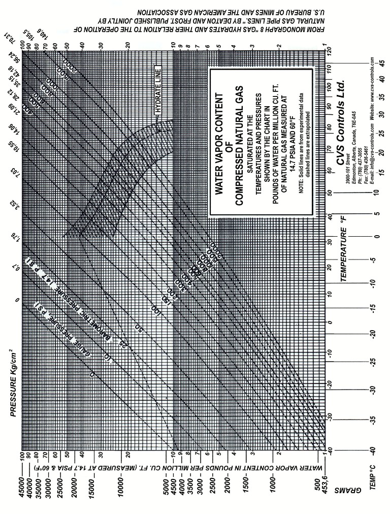
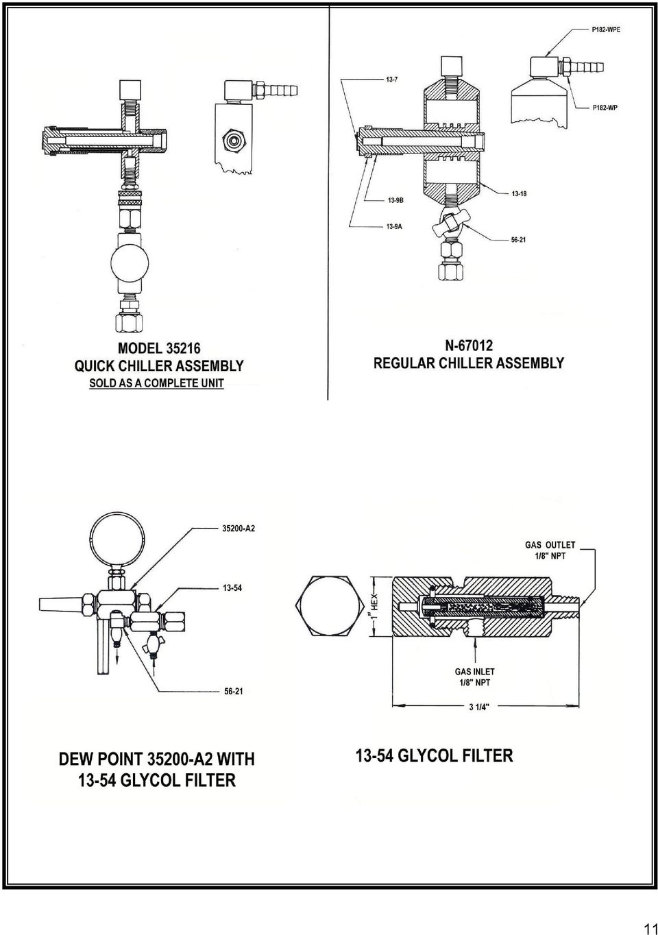
3 Test Procedure Continued, 4. Simultaneously observe mirror and thermometer, noting temperature at which a spot of moisture first appears in the center of stainless steel mirror. 5. Allow mirror to warm up, noting temperature at which moisture spot disappears. 6. Repeat 4 and 5 temperatures observed are within 2 F for appearance and disappearance of moisture spot. 7. Record the mean temperature observed as the Dew Point. Interpretation of Results Dew points may be converted to water content by use of various published curves. The Deaton and Frost Curve is attached as part of these instructions. Commercial propane is usually considered dry if the dew point is minus 15 F or below. Precautions Maximum working pressure of model No Model A-2 is 3000 psi at normal temperature. This pressure should not be exceeded. Both window and mirror may be easily removed for cleaning but care should be taken to avoid scratches. Viewing the dew point mirror through the observation mirror is not only convenient but is a safety precaution in case of window failure. Sometimes it may be necessary to run a test when atmospheric temperature is below the dew point of the gas in the pipeline. It will then be necessary to apply external heat to the sample line to avoid condensation between the pipeline and dew point apparatus. The heat should be applied as close to line as possible. In testing some gasses, it may be found that the natural gasoline dew point of the gas will be the same, or a higher temperature than the water dew point of the gas. It is necessary to visually differentiate between the two dew points. The gasoline wets the mirror and the film expands in an iridescent ring to cover the entire mirror surface, while the water condensate remains concentrated at the center. Use of the Glycol Filter The filter pressure chamber is installed on the inlet of the dew point tester. The pressure chamber has an easily removable end closure through which is inserted a copper tube containing the filter material. Internal dimensions are such that the sample gas, when introduced at the side of the pressure chamber is forced to flow through the filtering material before entering the dew point tester. At normal rates of flow, no pressure drop is introduced by the filter. As shown by the drawings, the installation of the glycol filter is made by removing the dew point tester inlet valve, screwing the filter into the opening from which the valve was removed, and relocating the inlet valve at the other side of the filter. In this position, the filter will not interfere with the dew point tester fitting on the tripod or in the carrying case. The copper tubing containing the filtering material is then inserted into the filter chamber and the end closed by the cap. An Oring sealing gasket is used and, consequently, the cap need only be screwed up hand tight. Operation of the dew point tester with the filter attached will be normal, except that a brief period of time should be allowed for the filtering material to attain equilibrium with the sample of gas. The length of this period will be determined by the quantity of water and glycol vapor in the sample gas, and may be found running dew points. Two consecutive dew points which check and which have no glycol vapor masking the mirror indicate satisfactory operation. The filtering material in the copper tube will eventually become saturated with glycol vapor and will no longer remove the vapor from the gas, after which it must be discarded and replaced with the new filter material. Again, the length of time that one charge of filter material will perform satisfactorily depends upon the glycol vapor content of the sample gas. It is important to keep the charge of the filtering, material small rather than to increase it in attempting to give it longer life as a larger volume of filter material will require proportionately longer times to come to equilibrium and give true dew points. 3

4 Consumables in Natural Gas The bureau of mines dew point tester is useful for determining water content or hydrocarbon dew point in natural and processed gas. Two major advantages are: 1. It can be operated at actual line pressure up to 3000 PSI without any mathematical corrections. 2. It is a primary instrument and does not rely on electronic circuits or mechanical cells, which need to be recalibrated or decontaminated. 3. The bureau of mines dew point tester uses the human eye to distinguish between the many possible condensables in field conditions. The actual photos below represent a few of these conditions and may be used as a guide to recognize the differences in appearance as the gas falls out on a chilled mirror using a CVS Controls dew point tester. Moisture Dew Point Hydrocarbon Dew Point (Using Gasoline) Clean Mirror Appears dark, smooth, and shiny Iridescent Colorful ring starts in center and expands quickly over entire mirror. Moisture Dew Point Dew forms a distinct opaque, grey spot approximately ¼-inch diameter directly in the center of mirror. Note the clean sharp edges at this point. Hydrocarbon Dew Point As hydrocarbons condense, droplets begin to form. ICE Point Crystals form an irregular pattern. They appear white against the gray dew point which has enlarged across the entire mirror. Hydrocarbon II As temperature continues to fall, droplets join together and run across mirror. Advanced ICE Point Crystals have joined together forming a very irregular pattern. Advanced Hydrocarbon Droplets collect into large drops which run down mirror. Eventually they freeze and turn white. 4

5 Hydrocarbon Dew Point Miscellaneous Dew Points (Using Propane) Hydrocarbon Dew Point A fog spreads across entire mirror with dark spot in center where hydrocarbons d Hydrocarbon II Dark spot enlarges and starts to become irregular shape. Alcohol Dew Point A white spot in the center of the mirror but has distinct edges unlike the sharp edges of the grey opaque water dew point. Alcohol II Spot becomes larger and increasingly white with a blue tint around outside Hydrocarbon III As temperature drops hydrocarbons begin to run down mirror. Advanced Alcohol Entire mirror becomes very white until droplets form. The drops get larger but continue to cling to mirror without freezing. Advanced Hydrocarbon With little surface tension, sheets of hydrocarbons stream down mirror and begin to puddle at bottom. Glycol Dew Point A light haze covers the entire mirror without beginning in middle. It does not change and will not evaporate. 5

6 3000PSI Dew Point Tester Bureau of Mines Type Model A-2 6

7 3000PSI Dew Point Tester Bureau of Mines Type Model A-2 Parts List Item Part Number Description Item Part Number Description 1 114V O-Ring, (2 req d) Regular Chiller Body Body Thermoguard Assembly Lucite Window Thermometer, -30 to F Thermometer, -35 to 50 0 C Observation Mirror Adjusting Knob Window Ret, Nut A Mirror insulating Ring Regular Chiller Carrying Case Stand Mirror Post Inlet and Outlet P182-WP Hose Barb Valve 25S14BM- 2.5 Safety Gauge, * Case Bracket Knob 3000 HP Mirror Ret. Nut B Mirror Insulating Sleeve CS* 11 P182-WPE Hose Elbow * Item Not Shown Case Assembly Accessories PART NUMBER DESCRIPTION A Dew Point Test Tank B Hose Assembly, c/w Re-Fill Adapter Tripod Refill Adapter Assembly 13-54* Glycol Filter, *Sold as a Complete Unit 7

8 1000PSI Dew Point Tester Bureau of Mines Type Model A-2 8

9 1000PSI Dew Point Tester Bureau of Mines Type Model A-2 Parts List Item Part Number Description Item Part Number Description 1 114V O-Ring Regular Chiller Body Thermoguard 2 124V O-Ring Assembly Thermometer, -30 to LP Body F 15 Thermometer, -35 to LP Window Ret, Nut LP 50 0 C Adjusting Knob Observation Mirror A Mirror insulating Ring Lucite Window S14BM Regular Chiller Mirror Inlet and Outlet Valve 2.5 Safety Gauge, LP Mirror Ret. Nut Carrying Case Stand Post 19 P182-WP Hose Barb * Case Bracket Knob CS* Case Assembly 11 P182-WPE Hose Elbow * Item Not Shown B Mirror Insulating Sleeve Accessories PART NUMBER DESCRIPTION A Dew Point Test Tank B Hose Assembly, c/w Tank Adapter Tripod Refill Adapter Assembly 13-54* Glycol Filter, *Sold as a Complete Unit 9

10 10

11 11
12 Head Office Street Edmonton, Alberta, Canada T6E 0A5 Office: (780) Fax: (780) Calgary Sales Office 205, Avenue NE Calgary, Alberta, Canada T2E 6Z3 Office: (403) Fax: (403) Website: Rev 3, June 2010 Printed in Canada CVS Controls Ltd. strives for the highest levels of quality and accuracy. The information included in this publication is presented for informational purposes only. CVS Controls Ltd. reserves the right to modify or change, and improve design, process, and specifications without written notice. Under no circumstance is the information contained to be interpreted to be a guarantee/warranty with regard to our products or services, applicability or use. Selection, use and maintenance are the sole responsibility of the end user and purchaser. CVS Controls assumes no liability for the selection use and maintenance of any product. 12

National Competency Based Skill Training Refrigeration and Air-conditioning Mechanic Logbook
 National Competency Based Skill Training Refrigeration and Air-conditioning Mechanic Logbook Trainee:... Training Provider:... Year:... Trainee Contact no:... Competency Based Skill Training Logbook Introduction
A discussion of condensate removal systems for clarifier and thickener drives for water and wastewater facilities.
 A discussion of condensate removal systems for clarifier and thickener drives for water and wastewater facilities. Richard L. Dornfeld, BSME, P.E. Staff Engineer September 25, 2014 Moisture can be a problem
Refrigeration Basics 101. By: Eric Nelson
 Refrigeration Basics 101 By: Eric Nelson Basics Refrigeration is the removal of heat from a material or space, so that it s temperature is lower than that of it s surroundings. When refrigerant absorbs
SPECIFICATION DIVISION 22 SECTION DESCRIPTION DIVISION 22 PLUMBING SECTION 220519 - THERMOMETERS, PRESSURE GAUGES, AND ACCESSORIES
 ARCHITECTURE, ENGINEERING AND CONSTRUCTION P00000000 0000 DOCUMENTS ARCHITECTURE & ENGINEERING 326 East Hoover, Mail Stop B Ann Arbor, MI 48109-1002 Phone: 734-764-3414 Fax: 734-936-3334 SPECIFICATION
CONDENSATION IN REFRIDGERATED BUILDINGS
 CONDENSATION IN REFRIDGERATED BUILDINGS By: Steve Salisbury Nov. 10, 2010 (revised Nov. 14, 2013) Introduction The following discussion reviews the basic causes of condensation in refrigerated buildings
Rusty Walker, Corporate Trainer Hill PHOENIX
 Refrigeration 101 Rusty Walker, Corporate Trainer Hill PHOENIX Compressor Basic Refrigeration Cycle Evaporator Condenser / Receiver Expansion Device Vapor Compression Cycle Cooling by the removal of heat
SECTION 5 COMMERCIAL REFRIGERATION UNIT 22 CONDENSERS
 SECTION 5 COMMERCIAL REFRIGERATION UNIT 22 CONDENSERS UNIT OBJECTIVES After studying this unit, the reader should be able to explain the purpose of the condenser in a refrigeration system. describe differences
DESIGN STANDARDS SECTION 23 60 00
 PART 1 - GENERAL 1.01 Work included: A. Piping, tubing and fittings. B. Piping specialties. C. Special duty valves. D. Refrigerants. E. Chillers. F. Refrigerant monitors. 1.02 General requirements: A.
A/C refrigerant system, overview
 Page 1 of 19 87-18 A/C refrigerant system, overview A/C refrigerant system, identification Typical A/C refrigerant system with expansion valve and receiver drier 1 - Evaporator 2 - Expansion valve 3 -
Contents and Nomenclature
 DX Coils Contents and Nomenclature Nomenclature... 1 Evaporator Coil Types EN... 2 EF... 2 ER... 2 EJ... 3 EK... 3 Evaporator Construction Connections... 4 Tubing... 4 Headers... 5 Tube Supports... 5 Coil
How To Understand Evaporator
 SECTION 5 COMMERCIAL REFRIGERATION UNIT 21 EVAPORATORS AND THE REFRIGERATION SYSTEM UNIT OBJECTIVES After studying this unit, the reader should be able to Define high-, medium-, and low-temperature refrigeration.
MUELLER FALLING FILM CHILLERS
 MUELLER FALLING FILM CHILLERS MUELLER FALLING FILM CHILLERS ARE DESIGNED TO COOL ANY FLUID TO WITHIN 2 F OF ITS FREEZE POINT. The primary application for Mueller s falling film chiller is to cool food-grade
CEILING CASSETTE FAN COIL UNIT
 CEILING CASSETTE FAN COIL UNIT Operation and Installation Manual MHCFC4W-04, 08, 12, 16 Four way ceiling cassette fan coil unit Please read this manual before using the fan coil unit. Installation and
Installation and Commissioning Manual Solar Stations FlowCon Max Evolution II
 Installation and Commissioning Manual Solar Stations FlowCon Max Evolution II 1 For your safety Table of Contents 1 For your safety... 3 1.1 About this manual... 3 1.2 Designated use... 3 1.3 Qualification
M SERIES REFRIGERANT COIL MODULE REFRIGERANT COILS for R-22, R-407C, R-410A
 Bulletin 20-20.2 / July 2012 M SERIES REFRIGERANT COIL MODULE REFRIGERANT COILS for R-22, R-407C, R-410A ➀ ➁ ➂ Model Number Key M 2430 C L 1 - A - ➀ Unit Type M=Modular Nominal Capacity 2430=24000 to 30000
01-3 6820-11 6820-11 AIR CONDITIONER GENERAL 1. SPECIFICATIONS AIR CONDITIONER REXTON 2010.01
 682011 013 GENERAL 1. SPECIFICATIONS 682011 014 682011 2. REPAIR INSTRUCTIONS 1) Precautions for Working with R134a R12 refrigerant and R134a refrigerant are not compatible. These refrigerants must never
2. AIRCONDITIONING AND REFRIGERATION
 2. AIRCONDITIONING AND REFRIGERATION 1. INTRODUCTION Air Conditioning and Refrigeration is an important area where in lot of self-employment opportunities are available. Now a day there is hardly a house
Total Heat Versus Sensible Heat Evaporator Selection Methods & Application
 Total Heat Versus Sensible Heat Evaporator Selection Methods & Application Scope The purpose of this paper is to provide specifying engineers, purchasers and users of evaporators in industrial refrigeration
It will be available soon as an 8.5 X 11 paperback. For easier navigation through the e book, use the table of contents.
 The System Evaluation Manual and Chiller Evaluation Manual have been revised and combined into this new book; the Air Conditioning and Refrigeration System Evaluation Guide. It will be available soon as
SECTION 23 81 03 - PACKAGED ROOFTOP AIR CONDITIONING UNITS NON-CUSTOM
 SECTION 23 81 03 - PACKAGED ROOFTOP AIR CONDITIONING UNITS NON-CUSTOM PART 1 - GENERAL 1.1 SUMMARY A. Section Includes: 1. Packaged rooftop air conditioning unit (5 tons and smaller). 2. Roof curb. 1.2
Condensate Treatment Solutions. CTS Series Eliminator II Oil-Water Separators
 Condensate Treatment Solutions CTS Series Eliminator II Oil-Water Separators 2 Condensate Treatment Solutions A Cleaner Environment & Reduced Disposal Costs Compressed air is compressed and discharged
Volkswagen Golf 5 2004-> VW Rabbit GTI 2006->
 Стр. 1 из 24 Volkswagen Golf 5 2004-> VW Rabbit GTI 2006-> 19-1 Cooling system components Warning! Hot steam may escape when opening expansion tank. Wear protective goggles and protective clothing to prevent
Flushing and Cleaning the A/C System
 Flushing and Cleaning the A/C System Once an AC system has been contaminated or has suffered a failure, the most important part of the AC service to restore the cooling performance to the system = FLUSHING
OASIS-PLUS 120V READ ALL INSTRUCTIONS BEFORE OPERATING READ ALL INSTRUCTIONS BEFORE OPERATING OZONE IS A POWERFUL OXIDIZER AND MUST BE USED WITH CARE
 OASIS-PLUS 120V INFORMATION & OPERATING INSTRUCTIONS READ ALL INSTRUCTIONS BEFORE OPERATING READ ALL INSTRUCTIONS BEFORE OPERATING OZONE IS A POWERFUL OXIDIZER AND MUST BE USED WITH CARE 56041852 WARNING:
Environmental Data Center Management and Monitoring
 2013 Raritan Inc. Table of Contents Introduction Page 3 Sensor Design Considerations Page 3 Temperature and Humidity Sensors Page 4 Airflow Sensor Page 6 Differential Air Pressure Sensor Page 6 Water Sensor
MAC-120HE-01 Air-Cooled Chiller
 MAC-120HE-01 Air-Cooled Chiller 10 Ton / 120,000 BTUH Air-Cooled Chiller 208/230-1-50/60 1 HVAC Guide Specifications Air-Cooled Liquid Chiller Nominal Size: 10 Tons Multiaqua Model Number: MAC-120HE-01
CONTAMINANT REMOVAL FROM CENTRIFUGAL SYSTEMS
 CONTAMINANT REMOVAL FROM CENTRIFUGAL SYSTEMS BULLETIN 240-10-3 June 2004 Supersedes June 1983 Many centrifugal systems get little maintenance. As a result they operate with the refrigerant highly contaminated
Open Cycle Refrigeration System
 Chapter 9 Open Cycle Refrigeration System Copy Right By: Thomas T.S. Wan 温 到 祥 著 Sept. 3, 2008 All rights reserved An open cycle refrigeration system is that the system is without a traditional evaporator.
User s Manual Laminar Flow Elements
 501:440-13 User s Manual Laminar Flow Elements 10920 Madison Avenue Cleveland, Ohio 44102 Tel: 216.281.1100 email:meriam@meriam.com Web:www.meriam.com 1 TABLE OF CONTENTS Subject Page Introduction... 3
Method 202 Dry Impinger Method for Determining Condensable Particulate Emissions from Stationary Sources. By: Paul Ottenstein
 Air Quality Issues in the Rocky Mountain Region PM2.5 Source Testing Method 201A Determination PM 10 and PM 2.5 Emissions from Stationary Sources (Constant Sampling Rate Procedure) Method 202 Dry Impinger
Powers Controls TH 192 HC Heating/Cooling Room Thermostat
 Powers Controls TH 192 HC Heating/Cooling Room Thermostat Technical Instructions Document No. 155-066P25 TH 192-2 50 60 70 80 70 TH0356R1 60 80 POWERS Description The TH 192 HC thermostats are proportional
CoolTop. A unique water cooled air-conditioning unit for server room cooling from the top AC-TOPx-CW-240/60
 CoolTop A unique water cooled air-conditioning unit for server room cooling from the top AC-TOPx-CW-240/60 Application CoolTop is a new, unique air conditioning unit especially designed for datacenters.
Sap Steady UV Unit for Maple Sap
 Cornell Maple Bulletin 203 (2007) Sap Steady UV Unit for Maple Sap by BRIAN CHABOT Overview Components The Sap-Steady unit from FPE Inc. (Macedon NY) has been designed to kill bacteria yeast, and some
Vacuum. How It Relates to Refrigeration And Air Conditioning Service
 Vacuum How It Relates to Refrigeration And Air Conditioning Service Moisture In A Refrigeration System Visible Moisture Water Droplets Uncommon, but it can occur Invisible Moisture Water Vapor Found in
Troubleshooting an Air Conditioning system. R D Holder Eng. Roger D Holder MSME
 Troubleshooting an Air Conditioning system R D Holder Eng. Roger D Holder MSME Troubleshooting of an air conditioning system is a step by step procedure. I have found that a 4 step procedure is the best
THE PSYCHROMETRIC CHART AND ITS USE
 Service Application Manual SAM Chapter 630-16 Section 3A THE PSYCHROMETRIC CHART AND ITS USE Psychrometry is an impressive word which is defined as the measurement of the moisture content of air. In broader
CPX/HT Series. REFRIGERATED AND HIGH TEMPERATURE DRYER 12 to 2400 CFM. High-performance products. Designed for you!
 CPX/HT Series REFRIGERATED AND HIGH TEMPERATURE DRYER 12 to 2400 CFM High-performance products. Designed for you! COMPRESSED AIR WATER CONTAMINATION Atmospheric air contains water in vapor form in different
CONDENSATION. Section Break (Next Page)
") CONDENSATION Elimination of condensation on or within walls and floors is as important as reducing the heat loss through the wall or floor. In addition to the moisture damage caused to buildings by condensation,
CONDENSATION Elimination of condensation on or within walls and floors is as important as reducing the heat loss through the wall or floor. In addition to the moisture damage caused to buildings by condensation,
Temperature affects water in the air.
 KEY CONCEPT Most clouds form as air rises and cools. BEFORE, you learned Water vapor circulates from Earth to the atmosphere Warm air is less dense than cool air and tends to rise NOW, you will learn How
TECHNICAL BRIEF Critical Point Drying
 TECHNICAL BRIEF Critical Point Drying Document Number Issue 2 Page 1 of 9 Critical Point Drying Technical Brief November 2009 Quorum Technologies Ltd main sales office: South Stour Avenue Ashford Kent
1932 Lexington Houston, Texas 77098-4220 (713) 524-4877. Recommendations for installation of cooling systems
 524-4877. Recommendations for installation of cooling systems") 1932 Lexington Houston, Texas 77098-4220 (713) 524-4877 The purpose for this information is to provide a better understanding of the HVAC equipment, components, designs, and installations, of HVAC system
1932 Lexington Houston, Texas 77098-4220 (713) 524-4877 The purpose for this information is to provide a better understanding of the HVAC equipment, components, designs, and installations, of HVAC system
Refrigerant Changeover Guidelines R-22 to R-407C. Leading the Industry with Environmentally Responsible Refrigerant Solutions
 Refrigerant Changeover Guidelines R-22 to R-407C Leading the Industry with Environmentally Responsible Refrigerant Solutions Copeland does not CFC advocate the wholesale changeover of HCFC HCFC refrigerants
RULE 1102. DRY CLEANERS USING SOLVENT OTHER THAN PERCHLOROETHYLENE
 (Adopted January 6, 1978)(Amended August 3, 1979)(Amended July 11, 1980) (Amended August 3, 1990)(Amended December 7, 1990) (Amended November 17, 2000) RULE 1102. DRY CLEANERS USING SOLVENT OTHER THAN
Glossary of Heating, Ventilation and Air Conditioning Terms
 Glossary of Heating, Ventilation and Air Conditioning Terms Air Change: Unlike re-circulated air, this is the total air required to completely replace the air in a room or building. Air Conditioner: Equipment
VACUUM REFRIGERATION SYSTEMS
 VACUUM REFRIGERATION SYSTEMS CHILL VACTOR The Croll-Reynolds CHILL-VACTOR is a chiller that uses a vapor flashing process. Water has a pressure-temperature relationship which is its boiling point. If its
Stainless Steel Single and Dual Circulation Kits
 Instruction Sheet P/N 160780 01 Stainless Steel Single and Dual Circulation Kits Introduction The single and dual high-pressure circulation kits allow you to vary and control the circulation rate of coating
Powers Controls TH 192 S Single Temperature Room Thermostat
 Technical Instructions Document No. 155-065P25 TH 192-1 Powers Controls TH 192 S Single Temperature Room Thermostat 50 60 70 80 TH0355R1 70 80 POWERS Description The TH 192 S thermostats are proportional
60.12. Depend-O-Lok FxE Expansion Coupling. System No. Submitted By Spec Sect Para Location Date Approved Date. DEPEND-O-LOK FxE EXPANSION COUPLING
 60.1 D-O-L FxE expansion couplings are a bolted, split-sleeve design that provides for expansion and contraction at the coupled joint. These couplings are furnished with restraint rings that, when affixed
SUB Universal water baths SBB Boiling baths JB, PB Unstirred water baths
 SUB Universal water baths SBB Boiling baths JB, PB Unstirred water baths Operating instructions Universal water baths SUB6: 6 litres SUB14: 14 litres SUB28: 28 litres SUB36: 36 litres Boiling baths SBB6:
PIPES AND TUBES FOR HVAC PIPING AND EQUIPMENT
 PIPES AND TUBES FOR HVAC PIPING AND EQUIPMENT GENERAL INFORMATION 1.1 This section applies to piping systems for chilled water, hot water, condenser water, steam, condensate return, fuel oil, refrigerant
Powers Controls Free Energy Band TH 193 HC Heating/Cooling Room Thermostat
 Document No. 155-068P25 TH 193-4 Powers Controls Free Energy Band TH 193 HC Heating/Cooling Room Thermostat 50 60 70 80 70 TH0356R1 60 80 POWERS Description The TH 193 HC thermostats are proportional dual
Watts Pure Water Systems
 Watts Pure Water Systems WM-120-PT Installation and Operation Manual Premier Water Systems Do not use with water that is microbiologically unsafe or of unknown quality without adequate disinfection before
Heat. Investigating the function of the expansion valve of the heat pump. LD Physics Leaflets P2.6.3.2. Thermodynamic cycle Heat pump
 Heat Thermodynamic cycle Heat pump LD Physics Leaflets P2.6.3.2 Investigating the function of the expansion valve of the heat pump Objects of the experiment g To study the operational components of the
DryWeight BulkVolume
 Test Procedure for BULK SPECIFIC GRAVITY AND WATER ABSORPTION OF AGGREGATE TxDOT Designation: Tex-201-F Effective Date: January 2016 1. SCOPE 1.1 Use this method to determine the bulk specific gravity
Figure 2 The fan and shroud also needs to be removed for access to the four a/c compressor bolts and removal of the compressor from the top.
 Here are some pictures to show what s required when replacing the A/C compressor, expansion valve and receiver/drier on a 2001 Volvo V70. Even if you don t replace these A/C parts these pictures can help
V47 Series Temperature Actuated Modulating Water Valves
 V47 Series Temperature Actuated Modulating Water Valves Master Catalog 125 Valves, Miscellaneous (Other Than Gas) Section V Product Bulletin V47 Issue Date 0286 Application The V47 modulating valves regulate
Troubleshooting HVAC/R systems using refrigerant superheat and subcooling
 Troubleshooting HVAC/R systems using refrigerant superheat and subcooling Application Note Troubleshooting and servicing refrigeration and air conditioning systems can be a challenging process for both
Additional Information. Paint Application
 Additional Information Paint Prepared by: International Paint Ltd. www.international-pc.com The information in this guideline is not intended to be exhaustive; any person using the product for any purpose
Cooling system components, removing and installing
 Engine BHW Cooling system components, removing and installing Page 1 / 24 19-1 Cooling system components, removing and installing Warning! When doing any repair work, especially in the engine compartment,
Characteristics of Evaporators
 Characteristics of Evaporators Roger D. Holder, CM, MSME 10-28-2003 Heat or Energy In this paper, we will discuss the characteristics of an evaporator coil. The variance of the operational condenses of
PBX Series Quick Fit Connector Bimetallic Steam Traps
 6262100/6 IM-P626-01 ST Issue 6 PBX Series Quick Fit Connector Bimetallic Steam Traps Installation and Maintenance Instructions 1. Safety information 2. General product information 3. Installation 4. Commissioning
Geothermal Alliance of Illinois. TXVs Theory and Fundamentals John Haug Senior Application Engineer Emerson Climate Technologies - Flow Controls
 Geothermal Alliance of Illinois TXVs Theory and Fundamentals John Haug Senior Application Engineer Emerson Climate Technologies - Flow Controls Thermal Expansion Valve Topics Anatomy Operation Terms &
Water Fired Chiller/Chiller-Heater. WFC-S Series: 10, 20 and 30 RT Cooling
 Water Fired Chiller/Chiller-Heater WFC-S Series: 1, 2 and 3 RT Cooling W E A R E F R I E N D L Y T O T H E E A R T H Water Fired SINGLE-EFFECT Chiller or Chiller-Heater Absorption Principle Cooling Cycle
Table V. Troubleshooting Checklist for Refrigeration Systems. Air or non-condensable gas in system. Inlet water warm.
 Table V Troubleshooting Checklist for Refrigeration Systems TROUBLE POSSIBLE CAUSE CORRECTIVE MEASURE High condensing pressure. Low condensing pressure. Air or non-condensable gas in system. Inlet water
Thermostatic valve Type AVTA
 MAKING MODERN LIVING POSSIBLE Data sheet Thermostatic valve Type AVTA Thermostatic valves are used for proportional regulation of flow quantity, depending on the setting and the sensor temperature. The
ENGINE COOLING SYSTEM
 ENGINE COOLING SYSTEM 1988 Toyota Celica 1987-88 TOYOTA Engine Cooling Systems Celica DESCRIPTION The basic liquid cooling system consists of a radiator, water pump, thermostat, cooling fan, pressure cap,
Medical Air Systems: Scroll
 GENERAL The Chemetron skid mount scroll medical air system is designed to provide medical breathing air for hospital and medical institutions. This system meets NFPA 99 requirements for Level 1 breathing
Indirect-Fired Storage Water Heater Models WH-30 through WH-80 INSTALLATION AND OPERATING INSTRUCTIONS
 Indirect-Fired Storage Water Heater Models WH-30 through WH-80 INSTALLATION AND OPERATING INSTRUCTIONS Contents Page Ratings and Specifications..................... 2 Installation Requirements......................
One Year Warranty. Stock U.S. # of Volts Weight CONN. Height Dia. Watts # GAL. Elements INS. Inches NATURAL GAS* Six Year Warranty
 One Year Warranty ELECTRIC Stock U.S. # of Volts Weight CONN. Height Dia. Watts # GAL. Elements INS. Inches Fused Ceramic Shield tank lining is corrosion-resistant for years of dependability. Adjustable
CHEMICAL CLEANING UNIT Product number: 737189
 CHEMICAL CLEANING UNIT Product number: 737189-1 - v.05/16 Content Page Intro 3 Specifications 4 Installation 5 Safety precautions 7 Maintenance 8 Spares and Accessories 8 Unitor Chemicals 9 Notes 10-2
CAUSTIC SOLUTION REPLACEMENT (Mud Safe CR) STABILITY TESTING
 STABILITY TESTING") CAUSTIC SOLUTION REPLACEMENT (Mud Safe CR) STABILITY TESTING Cormetrics Job #: 13-207 Prepared for: Heartland Energy Group Ltd. Date: March 20, 2013 Revision 2 Lab: Bay 4 2280 39 th Avenue NE, Calgary,
CAUSTIC SOLUTION REPLACEMENT (Mud Safe CR) STABILITY TESTING Cormetrics Job #: 13-207 Prepared for: Heartland Energy Group Ltd. Date: March 20, 2013 Revision 2 Lab: Bay 4 2280 39 th Avenue NE, Calgary,
Morrison Bros. Co. General Product Specifications
 Morrison Bros. Co. General Product Specifications Tank Mounted Spillbox The spill containment device is manufactured to contain spills and drips that may occur at the fill point on aboveground storage
How much do you know about HVAC? Try testing yourself with the following questions and then take a look at the answers on the following page.
 Demystifying HVAC Test Your HVAC Knowledge By Ron Prager How much do you know about HVAC? Try testing yourself with the following questions and then take a look at the answers on the following page. 1)
Self-operated Pressure Regulators Universal Pressure Reducing Valve Type 41-23
 Self-operated Pressure Regulators Universal Pressure Reducing Valve Type 41-23 Application Pressure regulators for set points from 5 mbar to 28 bar Valves in nominal sizes DN 15 to 100 Nominal pressures
Fixtures - Parts - Accessories to shampoo bowls
 Page 1??? - For what brand of bowl do you need parts??? Find out by looking on the bottom of the bowl, between the front and strainer, where molded in the bottom is the brand and model number. For example,
Replacement parts. WM97+ gas-fired water boiler Boiler Manual. OBTAIN PARTS ONLY THROUGH WEIL-McLAIN THE BOILER CONTAINS CERAMIC FIBER MATERIALS
 Replacement parts DO NOT SERVICE THE BOILER WITHOUT A WM97+ MAINTENANCE KIT AVAILABLE Failure to adhere to these guidelines can result in severe personal injury, death or substantial property damage. The
Installation Manual Gravity Solar Water Heater Evacuated Tube Integrated (Direct) System, unpressurized
 System, unpressurized") Installation Manual Gravity Solar Water Heater Evacuated Tube Integrated (Direct) System, unpressurized Gravity Solar System Installation Manual: This manual explains how to install a system of evacuated
Installation Manual Gravity Solar Water Heater Evacuated Tube Integrated (Direct) System, unpressurized Gravity Solar System Installation Manual: This manual explains how to install a system of evacuated
Activity: Clouds, Air Pressure and Temperature
 Activity: Clouds, Air Pressure and Temperature Materials A clean, clear, dry plastic 2-liter or larger beverage bottle with cap, thin liquid crystal temperature strip (available in aquarium supply stores),
Installer s Guide 18-AH39D1-13
 18-AH39D1-13 Cased Aluminum "Convertible" Coils 4TXCA018BC3HC** 4TXCA024BC3HC** 4TXCB025BC3HC** 4TXCB026BC3HC** 4TXCB031BC3HC** 4TXCB032BC3HC** ALL phases of this installation must comply with NATIONAL,
Refrigeration and Airconditioning Prof. M. Ramgopal Department of Mechanical Engineering Indian Institute of Technology, Kharagpur
 Refrigeration and Airconditioning Prof. M. Ramgopal Department of Mechanical Engineering Indian Institute of Technology, Kharagpur Lecture No. # 22 Refrigeration System Components: Compressor (Continued)
Refrigerant Charging Unit ICOGD. 020AH1000 Operating Manual. FR.8.2.4-09 İ-COLD 12.03.2014 Rev. 00
 E Refrigerant Charging Unit ICOGD 020AH1000 Operating Manual FR.8.2.4-09 İ-COLD 12.03.2014 Rev. 00 Contents Technical Specifications... 20 Safety... 21 A/C System... 22 Components... 23 Control Panel...
OEM Manual MODEL 2350 ELECTRONIC DUAL CYLINDER SCALE
 OEM Manual MODEL 2350 ELECTRONIC DUAL CYLINDER SCALE Scaletron Industries, Ltd. Bedminster Industrial Park 53 Apple Tree Lane P.O. Box 365 Plumsteadville, PA 18949 USA Toll Free: 1-800-257-5911 (USA &
MAYTAG MFD2560HEB NACIONAL E IMPORTACIÓN CABINET BACK
 CABINET BACK 1 CABINET BACK 1 12575101ED BACK, MACH COMP 2 67004098 COVER, WATER VALVE 3 M0238616 SCREW, SM 4 M0251015 SCREW 5 B5759649 GASKET, MC BACK 6 67004092 BLOCK, FILTER 7 M0211018 SCREW, SM 8 67003729
Sensors for Air-conditioning in Automobiles
 Sensors for Air-conditioning in Automobiles www.epcos.com Contents...3 1. Evaporator sensors...3 2. Integral sensors...4 3. Solar sensors...4 4. Icing protection switches...5 5. External temperature sensors...5
Constantemp Double Wall Low pressure steam-water Heater F-340LDW,F-640LDW, F-940LDW and F-1240LDW
 Installation, Operating and Maintenance Instructions 90/4.5.5 Rev. 0 Constantemp Double Wall Low pressure steam-water Heater F-340LDW,F-640LDW, F-940LDW and F-1240LDW Table of Contents SECTION I... 2 INSTALLATION...
Hot, Warm and Cold Mineral Water Cooler [Models Cool18, Cool25, Cool36, Cool50, Cool75, Cool100]
![Hot, Warm and Cold Mineral Water Cooler [Models Cool18, Cool25, Cool36, Cool50, Cool75, Cool100]](/thumbs/26/7741864.jpg "Hot, Warm and Cold Mineral Water Cooler [Models Cool18, Cool25, Cool36, Cool50, Cool75, Cool100]") Hot, Warm and Cold Mineral Water Cooler [Models Cool18, Cool25, Cool36, Cool50, Cool75, Cool100] PLEASE READ BEFORE INSTALLATION TO PREVENT DAMAGE TO THE COOLER HOT WATER TANK STEAM EXAUST VENT (CAUTION!)
Hot, Warm and Cold Mineral Water Cooler [Models Cool18, Cool25, Cool36, Cool50, Cool75, Cool100] PLEASE READ BEFORE INSTALLATION TO PREVENT DAMAGE TO THE COOLER HOT WATER TANK STEAM EXAUST VENT (CAUTION!)
Installation Manual. Solar Pool Heating System. Read the complete manual before beginning the installation
 Solar Pool Heating System Installation Manual Read the complete manual before beginning the installation 1. Sizing the System Visit www.techno-solis.com to size the system using the sizing calculator.
COIL INPUT SCREENS. ITEM NUMBER: Always use a 1 through? In this field you might also use a dash and place quantity of coils here.
 COIL INPUT SCREENS Example of a Water Coil Input Screen: (*please see the appendix for an example of an Evaporator, Steam or Condenser Coil input screen) PHYSICAL DATA ITEM NUMBER: Always use a 1 through?
Fiberstars Lighted Laminar Flow Fountain Installation Manual
 Fiberstars Lighted Laminar Flow Fountain Installation Manual 79-15037-00 REV Xx http://www.fiberstars.com Page 1 of 8 SAVE THESE DIRECTIONS! These directions are provided to ensure the proper installation
BRAZED PLATE INSTALLATION MANUAL
 www.brazedplate.com BRAZED PLATE INSTALLATION MANUAL S.E.C. Heat Exchangers P.E.I. CANADA C0A 1A0 tel; 902-659-2424 fax; 902-659-2800 Table of Contents Description...2 Mounting position...3 Piping connections......3
EXPERIMENT 10 CONSTANT HEAD METHOD
 EXPERIMENT 10 PERMEABILITY (HYDRAULIC CONDUCTIVITY) TEST CONSTANT HEAD METHOD 106 Purpose: The purpose of this test is to determine the permeability (hydraulic conductivity) of a sandy soil by the constant
FLASH TANK ECONOMIZER PRODUCT GUIDE
 FLASH TANK ECONOMIZER PRODUCT GUIDE Overview A flash tank is used to recover blowdown energy in the form of flash steam and blowdown. This can only be used with a deaerator or some other pressurized device.
The Axial Flow Valve. Class 300/600. sales@elster-instromet.co.uk www.elster-instromet.com SERIES
 The Axial Flow Valve SERIES Class 300/600 sales@elster-instromet.co.uk www.elster-instromet.com THE AXIAL FLOW VALVE - SERIES 300/600 A UNIQUE REGULATOR What is the Axial Flow Valve? The Axial Flow Valve
Pipe threads for tubes and fittings where pressure-tight joints are not made on the threads. (requires PTFE sealing tape or liquid sealant).
.") Fittings for CO 2 Pipe Threads Pipe thread references quoted in this catalogue conform with the requirements specified in the latest issue and amendments of the following ISO Standards: ISO 7-1 (BS21)
Fittings for CO 2 Pipe Threads Pipe thread references quoted in this catalogue conform with the requirements specified in the latest issue and amendments of the following ISO Standards: ISO 7-1 (BS21)
AFE424 SERVICE PARTS
 This is the parts list for the AFE. When looking up part numbers, always check the complete model and serial numbers to be certain of ordering the correct parts. The Air Cooled model has also been manufactured
RI-215A Operator s Manual. Part Number: 71-0045RK Revision 0 Released: 10/3/05
 RI-215A Operator s Manual Part Number: 71-0045RK Revision 0 Released: 10/3/05 Warranty RKI Instruments, Inc., warrants gas alarm equipment sold by us to be free from defects in materials and workmanship,
Model 2128 AIR COMPRESSOR PUMP Operating Instructions
 Model 8 AIR COMPRESSOR PUMP Operating Instructions Assembly of pump Connection to cylinder and charging ) Connect the air hose to the air cylinder and tighten with spanner. Do not over tighten. Note; the
THE HUMIDITY/MOISTURE HANDBOOK
 THE HUMIDITY/MOISTURE HANDBOOK Table of Contents Introduction... 3 Relative Humidity... 3 Partial Pressure... 4 Saturation Pressure (Ps)... 5 Other Absolute Moisture Scales... 8 % Moisture by Volume (%M
Solar Hot Water Heaters
 Solar Hot Water Heaters Three High Vacuum Water inlet Stainless Steel screw Gel seal and insulation Water outlet Dust proof seals Non Pressure Models Details ASWH-1b ( Color Painted 304 ) ASWH-1c ( stainless
Refrigerant Changeover Guidelines R-22 to R-407C. Leading the Industry with Environmentally Responsible Refrigerant Solutions
 Refrigerant Changeover Guidelines R-22 to R-407C Leading the Industry with Environmentally Responsible Refrigerant Solutions Emerson Climate CFC Technologies, Inc. does not advocate the HCFC wholesale