VDO SERIES-Z FOR CYCLING
|
|
|
- Rosanna Whitehead
- 10 years ago
- Views:
Transcription
1 VDO SERIES-Z FOR CYCLING INSTRUCTION MANUAL / BEDIENUNGSANLEITUNG / MANUEL D INSTALLATION ET D UTILISATION / HANDLEIDING / MANUALE D INSTALLAZIONE E FUNZIONAMENTO INSTRUKCJA OBSLUGI LICZNIKA / INSTALACION Y OPERACIÓN MANUAL

2 My Settings AGE: WEIGHT: MAX HEARTRATE: LIMIT 1: LOW: HIGH: LIMIT 2: LOW: HIGH: LIMIT 3: LOW: HIGH: RECOVERY TIME: RECOVERY PULSE: BIKE 1 WEIGHT: BIKE 2 WEIGHT: BIKE 1 WHEELSIZE: BIKE 2 WHEELSIZE: BIKE 1 SERVICE INTERVALL: BIKE 2 SERVICE INTERVALL: HOME ALTITUDE: FURTHER SETTINGS:

3 Picturebook P01 ONLY FOR MODELS Z2 PC-LINK / Z3 PC-LINK CD-ROM * PC-Sport 8x * Watch out: old batteries require special disposal Please read instructions for end-off-life disposal treatment

4 Picturebook P02 OPEN CLOSE OPEN CLOSE!!

5 ! Picturebook P03 ONLY FOR MODELS Z2/Z2 PC-LINK Z3/Z3 PC-LINK OPEN CLOSE

6 Picturebook P04/05 90

7 Picturebook P06 LOCK UNLOCK 1.LOCK 2.CLICK 2.UNLOCK

8 Picturebook P mm
9 Picturebook P08 ONLY FOR MODELS Z2/Z2 PC-LINK Z3/Z3 PC-LINK

10 Picturebook P09 P09-2 CLOSE OPEN
11 Picturebook P10 1x WS in mm / inch Tire size WS in mm KMH WS in inch MPH , x1, x1, , x1 3/ , x1, , x , x1, , x1, , x1, , x1, ,1 n/a 26 x 1, , x2, ,7 n/a 26 x 2, , x2, , x1 3/ ,9 Tire size WS in mm KMH WS in inch MPH , x3/ x1 1/ , x1, , x1, , x1 1/ , x1 3/ , x18C , x20C , x23C , x25C , x28C , x32C , x37C , x40C ,6

12 Picturebook P11 ONLY FOR MODELS Z2 PC-LINK Z3 PC-LINK

13 EN Congratulations With your selection of a VDO Z2 PC-Link you have opted for high-quality sports information computer. In order to fully benefit from the potential of the computer, we recommend that you carefully read this manual. It contains all operating instructions and many useful tips. We extend our best wishes for enjoyment and satisfaction when riding with your VDO computer. VDO Cyclecomputing Cycle Parts GmbH Package contents >>> P01 First, please ensure that the contents of this package are complete: 1 VDO computer Z2 PC-Link 1 VDO speed transmitter 1 VDO pulse-chest belt incl. elastic strap, incl. battery 1 battery for computer, 3 V type handlebar holder 1 wrist band holder 1 lock for the wrist band holder 1 spoke magnet 1 docking station with USB cable for data transfer to the PC 1 CD-ROM with analysis software for the PC 8 cable ties Optional extension set: VDO cadence transmitter >>> P... Reference to the appropriate pages in the picture book.this is where the content is again presented in picture form, e.g.: >>> P01 P01 page 1 in the picture book 4

14 INSTRUCTION MANUAL TABLE OF CONTENTS 1.1. General 1.2. Important instructions for the digital wireless system 1.3. Control system - operation Operating mode Setting mode 1.4. The display 1.5. Extension options & accessories 2. INSTALLATION 2.1. Battery installation Battery installation - computer and speed/cadence transmitter Battery installation pulse-chest belt Installation - holder/computer/transmitter/magnet 2.3. Putting on the pulse-chest belt 2.4. Mounting the computer on the wrist band 3. INITIAL OPERATION 3.1. Initial operation, AC-button 3.2. Language selection 3.3. Manual pairing - INITIAL operation wireless system Initial operation - pulse transmitter Initial operation - speed transmitter Initial operation - cadence transmitter 4. GENERAL SETTINGS 4.1. Setting the language 4.2. Setting time & date 4.3. Setting the alarm, alarm clock 5. BICYCLE FUNCTION SETTINGS 5.1. Measuring and setting wheel size/s 5.2. Changing wheel size 5.3. Setting total kilometers 5.4. Bike check / service interval 6. PERSONAL SETTINGS IMPORTANT NOTE The personal settings are prerequisite for calculating maximum pulse, training zones, and calorie consumption. Ensure that you make the personal settings first so that you can fully utilize the possibilities offered by the computer Personal settings with manual max. pulse entry 6.2. Personal settings with automatic max. pulse calculation 7.PULSE FUNCTION SETTINGS 7.1. Automatic calculation of pulse limit values 7.2. Manual entry of pulse limit values 7.3. Selecting the training range 7.4. Setting the recovery measurement (pulse or time) 5

15 EN 8. RESET MODE 8.1. Resetting trip data 8.2. Reset total ride time 8.3. Resetting the total distance meter 8.4. Resetting the Navigator 8.5. Resetting to factory settings (AC button) 9. OPERATION MODE SELECTION Selecting the operation mode: Bike mode or walk mode 10. OPERATION MODE Function overview Fast pairing after interruption > 15 minutes GETTING STARTED The permanent functions in the display to Quick overview - functions/operation/reset/max. values 11. RIDING WITH THE NAVIGATOR Selecting Navigator mode Resetting the Navigator at the orientation point 12. THE TIMING FUNCTIONS Selecting the timing function Setting the timer (when selecting timer 1 or timer 2 or timer 1 + 2) Setting timer repeats (when selecting timer 1 + 2) Setting the countdown (when selecting countdown timer) Lap timer Stopwatch 13. TRAINING WITH THE PULSE FUNCTIONS Training with the stopwatch Training with timer 1 / timer 2 / timer Training with the countdown timer Training with the lap timer 14. THE DATA RECORDING FUNCTION & TRANSFER OF DATA TO THE PC Starting/stopping data recording Transferring data to your PC Selection of the recording interval 15. SLEEP MODE 16. TROUBLESHOOTING 17. GUARANTEE CONDITIONS 18. TECHNICAL SPECIFICATIONS 6
 12.3. Setting timer 1 + 2 repeats (when selecting timer 1 + 2) 12.4.")
16 INSTRUCTION MANUAL 1.1. GENERAL 1.2 IMPORTANT INSTRUCTIONS FOR THE DIGITAL WIRELESS SYSTEM Your VDO Z2 PC-Link works entirely without cable; it works with triple digital wireless transmission based on well-established ANT+Sport wireless protocol. The ANT+Sport wireless protocol has already been successfully implemented by manufacturers such as Garmin, Specialized, and Suunto. Speed signals, cadence signals (optional), as well as heart rate data are transmitted to the respective receiver (computer) as digital and coded signals. Signal coding ensures that only the data of your own pulse, speed, and cadence (optional) transmitters are processed (this is advantageous when riding in a group). The ANT+Sport digital technology is significantly more reliable than the technology of older analog systems. The ANT+Sport technology uses standard industrial wireless components, and it can best be compared to the technology used in modern WLAN networks. The connection between transmitter and receiver is more stable, and subject to significantly less frequent malfunction, and it is virtually completely safeguarded from data loss. The speed transmitter has a memory component that buffers data every 65 sec. Thus no data is lost if there is a malfunction lasting for this duration.after the malfunction this data will be resent to the computer. Subsequently the following data will be updated: Daily distance Ride time Average speed Navigator Total distance Total ride time After a malfunction the data can change suddenly = updating the computer. Initial operation of a completely digital system requires somewhat more care than does initial operation of conventional analog systems. The first time batteries are inserted, or after a battery change, the transmitter automatically generates a new code. The computer has to learn this code. To do this you must execute a DIG CONNECT SET. Strictly follow the instructions in chapter 3.3 to do this. ATTENTION: Your VDO computer is not suitable for use on motorcycles. 1.3 CONTROL SYSTEM - OPERATION The control system of your computer is based on dual assignment of the 4 main buttons. In this regard the devices distinguishes between operation mode and setting mode. 7
, as well as heart rate data are transmitted to the respective receiver (computer) as digital and coded signals.")
17 EN OPERATION MODE - use this mode to display all information Button assignment is shown on the housing. OPERATION MODE Not used in Operation Mode Displaying all pulse measurement functions and interval data stored Manual start/stop of the stopwatch and of all other timers Displaying the bike functions 1 Z2 PC-LINK Displaying the bike functions 2 TIMER AVG PULSE CLOCK MAX PULSE TRIP DIST PULSE MAX% RIDE TIME NAVIGATOR LIMIT AVG SPEED ODO BIKE 1 TIME IN MAX SPEED ODO BIKE 2 TIME ABOVE CAD AVG ODOTOTAL TIME BELOW CAD MAX TIME BIKE1 LAP REC TIME BIKE2 CALORIE TOTALTIME RECOV TIME Not in walk mode! 8

18 INSTRUCTION MANUAL SETTING MODE - use this mode to make all settings. The assignment of buttons is on the buttons To go to setting mode: Press button ç for 3 seconds SETTING MODE or Z2 PC-LINK LANGUAGE SELECT NAVIGATOR SET Chap Chap WHEELSIZE SET Chap WHEELSIZE CHANGE Chap CLOCK SET Chap PERSON DATA SET Chap ALARM SET Chap OP MODE SELECT Chap. 9. TIMER SETTINGS Chap BIKE CHECK SET Chap ODOMETER SET Chap DIG-CONNECT SET Chap PULSE LIMIT SETTINGS Chap PC LINK SELECT Chap RECOVERY SET Chap å (Once) = last step, or back one menu level (Hold) = return to start menu : Select/confi rm displayed option In the highest menu level select the next menu level Page down within the menu level In SET mode (number fl ashes): Reduce number Page up within the menu level ƒ: In SET mode (number fl ashes): Increase number After subsequent confi rmation of a setting the computer automatically returns to operation mode. 9

19 EN 1.4. THE DISPLAY The display of your VDO computer is comprised of three large areas. The following information is displayed in operation mode: * If the computer is worn as a sport watch then the temperature can be falsifi ed by body warmth. Header - actual cadence (optional) 3. Footer: DOT matrix full-text - display of the selected/displayed function - In setting mode menu prompting (chapter 5-11) provides information about what is shown in the display. MIDDLE BAR - Actual heart rate - Actual speed - Heart icon for signal reception of chest belt transmitter - Alarm icon when leaving the target heart rate range - Timing indicator for ongoing timing function - Indicator for set alarm/alarm clock - LAP recording indicator - Walk mode indicator - Selection indicator bike 1 / bike 2 - DATA Recording - icon for ongoing Data Recording - Arrow indicators for comparing the actual speed to the average speed - Service interval icon indicates that bike is due for service 10

20 INSTRUCTION MANUAL 1.5. EXTENSION OPTIONS & ACCESSORIES Extension option: You have the possibility of extending your computer with the cadence extension set In this case the following cadence functions are available to you: Actual cadence Average cadence Maximum cadence ORIGINAL EQUIPMENT In addition you can also get the following original VDO replacement parts from your dealer Designation article number Universal handlebar holder - wireless art. no Magnet S/M for speed impulses art. no Magnet L/XL for speed impulse art. no Cadence magnet art. no Speed transmitter art. no Pulse transmitter (incl. elastic chest belt) art. no Elastic chest belt for pulse transmitter article art. no Replacement docking station art. no Cadence kit art. no Wrist band art. no Wrist band twist-click lock art. no Universal mount kit art. no When purchasing look for the VDO Cyclecomputing original equipment logo. Only products bearing this logo are authorized by VDO Cyclecomputing for use with your computer. 2. INSTALLATION 2.1. BATTERY INSTALLATION BATTERY INSTALLATION - COMPUTER AND SPEED/CADENCE TRANSMITTER >>> P02 step 1 Insert the battery into the computer/transmitter housing with the + pole up. step 2 Ensure that the battery is not tilted. step 3 Ensure that the rubber seal lies smoothly on the lid of the battery compartment. step 4 Insert the battery compartment lid into the opening and use a coin to firmly turn the battery door to right until the stop (approximately 1/3 turn) TIP for changing batteries: VDO recommends changing the batteries yearly to avoid undesired data loss. Thus strictly ensure that you note the entered wheel sizes as well as the previous ridden kilometers for bike 1 & bike 2, as well as the total altitude difference for bike 1, bike 11

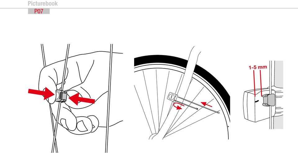
21 EN 2, and the altitude difference walked. Reprogram this information after inserting the new batteries BATTERY INSTALLATION PULSE-CHEST BELT >>> P03 Your VDO is shipped with the battery installed in the pulse-chest belt. Proceed as follows when later inserting a replacement battery: step 1 Insert the battery into the chest-belt housing with the +pole up. step 2 Ensure that the battery is not tilted. step 3 Strictly ensure that the rubber seal lies smoothly on the battery compartment lid. step 4 Insert the battery compartment lid into the opening and use a coin to firmly turn the battery door to right until the stop (approximately 1/3 turn) 2.2. INSTALLATION - HOLDER/COMPUTER/TRANSMITTER/MAGNET a. Holder >>> P04 / 05: Your VDO computer is shipped with a universal handlebar holder. step 1 You can mount the holder either on the handlebar or the stem. If you are installing the holder on the handlebar decide whether you want it on the right side or the left side. If installing on the stem, loosen the screws in the holder and turn the foot of the holder to stem installation. Then screw the foot firmly onto the holder again. step 2 Route the cable ties through the provided eyes of the holder foot and pull both of them tight. b. Computer >>> P06 The VDO twist-click system securely connects the computer to the handlebar holder. step 1 Insert the computer, turned to the left approximately 45 degrees (10 o clock position) into the holder. step 2 Twist the computer to the right until it audibly engages (clicks) in the holder system (12 o clock position). step 3 To remove the computer turn it to the left (do not press or pull). c. Speed transmitter and magnet >>> P07 Mount the transmitter on the same side of the handlebar that the computer is mounted on. If you have installed the holder on the stem then we recommend mounting the transmitter on the left side. step 1 Loosely fasten the transmitter on the fork with cable ties (do not tighten). step 2 Place the spoke magnet on a spoke step 3 Align the spoke magnet to the transmitter marking with a clearance of approximately 3 mm and click it together. step 4 Align transmitter and magnet relative to each other and tighten the cable tie on the transmitter. Please pay attention to the maximum distances: - Maximum transmitter-computer distance = 120 cm - Transmitter-magnet distance: 3 mm to a maximum of 10 mm 12
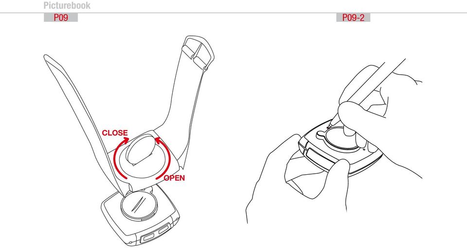
22 INSTRUCTION MANUAL 2.3. PUTTING ON THE PULSE-CHEST BELT >>> P08 step 1 First connect the one side of the pulse transmitter with the elastic strap, as shown. Press the ends of the pulse-chest belt into the plastic holder of the elastic strap step 2 Place the pulse transmitter just below your chest and guide the elastic strap over your back to the other end of the pulse transmitter step 3 Connect the second end of the plastic strap to the pulse transmitter step 4 Use the size adjustment of the elastic strap to adjust the chest belt to your chest size Please note: - Do not adjust the chest belt too loose; if it is too loose it can slip if there are jolts (e.g. when walking) - When putting on the chest belt moisten the electrodes so that troublefree function is also ensured when starting exercise, before contact is established through sweat. - Range of the pulse-chest belt transmitter = 0.90 m 2.4. MOUNTING THE COMPUTER ON THE WRIST BAND >>> P09 step 1 Insert the computer into the opened wrist band step 2 Insert the lock into the wrist band holder from below step 3 Turn the lock with a coin to tighten it ATTENTION: Never use a screwdriver to operate the lock. This could damage the lock (if the lock should be damaged then you can get the lock as original replacement part) 3. INITIAL OPERATION 3.1. INITIAL OPERATION, AC-BUTTON >>> P09-2 After inserting the batteries we recommend that you first reset the device to factory settings to ensure that no residual data from the quality control process remains in the computer. This puts the computer into an assured start mode. - Press the AC button for approximately 2 seconds with a sharp object, such as a pencil 3.2. LANGUAGE SELECTION 3sec. ç Setting mode LANGUAGE SELECT step 2 Confirm LANGUAGE SELECT with M step 3 ƒ Press the up or down button until the desired language appears step 4 Confirm your language selection with M 3.3. MANUAL PAIRING - INITIAL OPERATION WIRELESS SYSTEM For initial operation of the digital wireless system manual pairing must ALWAYS be executed. Manual pairing ensures that the computer learns the coding of the transmitter you are using. step 1 Insert the computer into the twist-click holder step 2 Ensure that there are no ANT+Sport digital transmitters other than the transmitter you are using within a 5-meter area around the computer Your computer will randomly select one of 128,000 codes. This ensures that signals of other transmitters are not received or processed (e.g. when riding in a group). If dashes are shown in the display, in spite of pairing, you must repeat the manual pairing process. In doing so 13
23 EN ensure that the electrodes of the pulse transmitter belt are wet, or that the distance between the magnets and the speed/cadence transmitter is not greater than 5 mm. ATTENTION: Your computer can save the codes of up to 5 transmitters 1. Speed transmitter of bike 1 2. Speed transmitter of bike 2 3. Cadence transmitter of bike 1 (optional) 4. Cadence transmitter of bike 2 (optional) 5. Pulse transmitter INITIAL OPERATION - PULSE TRANSMITTER Put the pulse transmitter belt on and moisten the electrodes (chapter 2.3) 3sec. ç Setting mode LANGUAGE SELECT ƒ Select DIG CONNECT SET Display DIG CONNECT ƒ Select PULSE SEARCH PULSE PAIRING PAIR DONE appears in the display after several seconds if the pulse transmitter was found. Automatic return to the TRIP DIST menu. If the pulse transmitter was not found PULSE REPEAT appears. Use to repeat the pairing process for the pulse transmitter. For troubleshooting see chapter INITIAL OPERATION - SPEED TRANSMITTER 3sec. ç Setting mode LANGUAGE SELECT ƒ Select DIG CONNECT SET Display DIG CONNECT ƒ Select SPEED SEARCH SPEED PAIRING Now turn the front wheel (both magnet and transmitter must be already mounted) PAIR DONE appears in the display after several seconds if the speed transmitter was found. Automatic return to the TRIP DIST menu SPEED REPEAT appears if the speed transmitter was not found. Use to repeat the pairing process for the speed transmitter. For troubleshooting see chapter INITIAL OPERATION - CADENCE TRANSMITTER (OPTIONAL EXTENSION see chapter 1.5) 3sec. ç Setting mode LANGUAGE SELECT ƒ Select DIG CONNECT SET Display DIG CONNECT ƒ Select CADENCE SEARCH CADENCE PAIRING Now turn the crank (magnet and transmitter must be already mounted) PAIR DONE appears in the display after several seconds if the cadence transmitter was found. Automatic return to the TRIP DIST menu If the cadence transmitter was not found CADENCE REPEAT will be displayed. With repeat the pairing for the cadence transmitter For troubleshooting see chapter
24 INSTRUCTION MANUAL IMPORTANT NOTE / Re-open of transmitter search for the receive channel after interruption If no signal is received from an already paired transmitter after 15 minutes (for example riding without chest belt for Z2 and Z3, also PC-LINK models), the receive channel will be closed for this transmitter. In this case your VDO computer will show dashes for the respective function in the display. To re-open all receive channels press the ç and buttons at the same time: Now your VDO computer will again receive all previously paired transmitters that are in range. 4. GENERAL SETTINGS 4.1. SETTING THE LANGUAGE 3sec. ç Setting mode LANGUAGE SELECT LANGUAGE SELECT ƒ Select LANGUAGE ENGLISH Automatic return to TRIP DIST Language selection done SETTING TIME & DATE 3 sec. ç Setting mode LANGUAGE SELECT ƒ CLOCK SET SET HOUR?CONTINUE? ƒ Setting hours SET MINUTES?CONTINUE? ƒ Setting minutes SET YEAR?CONTINUE? ƒ Setting the year SET MONTH?CONTINUE? ƒ Setting the month SET DAY?CONTINUE? ƒ Setting the day CLOCK?SET OK? CLOCK SET DONE Automatic return to CLOCK SETTING THE ALARM, ALARM CLOCK 3 sec. ç Setting mode LANGUAGE SELECT ƒ ALARM SET ALARM ON or ALARM OFF ( ( to switch on) When the alarm clock is switched off setting mode ends automatically by. SET HOUR?CONTINUE? ƒ Selecting the hours value SET MINUTES?CONTINUE? ƒ Selecting the minutes value ALARM?SET OK? ALARM SET DONE! Automatic return to the operation mode for CLOCK. Setting the alarm clock done. The alarm clock icon is now shown in the display (center bar left). 5. BICYCLE FUNCTION SETTINGS 5.1. MEASURING AND SETTING WHEEL SIZE/S In order for your VDO computer to measure correctly you must first measure the circumference of your wheel. If this value is set incorrectly then all values calculated on the basis of this value, such as speed, trip, 15
25 EN etc. will be wrong. To use your VDO computer on two different bikes e.g. mountain bike and road bike you can enter two different wheel sizes. Measuring the wheel circumference: step 1 Align the valve of the front wheel so that it is precisely vertical to the ground step 2 Mark this point on the ground with a line (use chalk for example) step 3 Push the bike one wheel rotation forward until the valve is again vertical to the ground. step 4 Mark this point on the ground as well. step 5 Measure the distance between the two marks. The result is your wheel circumference (=roll circumference). step 6 Enter the wheel circumference as described below into your VDO computer. ATTENTION: If you have selected KMH display then you must enter the wheel circumference in mm. If you have selected MPH display then enter the wheel circumference in inches. The values listed in table >>> P10 are approximate values. These values deviate depending on brand of tire, tire height and tire tread. Setting wheelsize: 3 sec. ç Setting mode LANGUAGE SELECT ƒ WHEELSIZE SET WHEELSIZE KMH-DISPLAY or WHEELSIZE MPH- DISPLAY ( to change to mph) WHEELSIZE 1 SET SIZE?CONTINUE? ƒ Set wheel size 1 in mm (keep button depressed for fast run-through) WHEELSIZE 1?SET OK? WHEELSIZE 1 SET DONE Automatic change to ƒ Set wheel size 2 in mm (keep button depressed for fast run-through) WHEELSIZE 2?SET OK? WHEELSIZE 2 SET DONE Automatic return to operation mode for TRIP DIST. If you do not want to set wheel size 2 then hold å to return to TRIP DIST operation mode. Attention: Factory settings for bike 1 = 2155 mm and for bike 2 = 2000 mm. If you do not enter wheel sizes the computer will work with the factory settings. The values measured in this manner for speed, distance, etc. can deviate from the actual values CHANGING THE WHEEL SIZE With wheel size you change the computer from bike 1 (e.g. road bike) to bike 2 (e.g. mountain bike). The computer now works with the settings for bike 2. 3 sec. ç Setting mode LANGUAGE SELECT ƒ WHEELSIZE CHANGE ƒ WHEELSIZE 1 or WHEELSIZE 2?SET OK? ƒ Changing the wheel size WHEELSIZE SET DONE Automatic return to TRIP DIST 16
26 INSTRUCTION MANUAL Wheel size set done Display of the actual wheel size in the center bar of the display, right bottom (1 or 2) 5.3. SETTING TOTAL KILOMETERS You can program the total distances into your VDO computer that get lost when changing batteries or that you have previously counted with a different device. This function is available for both wheel sizes (both bikes). Setting total KM 1 or 2 3 sec. ç Setting mode LANGUAGE SELECT ODOMETER SET ODO BIKE 1 SET or ƒ ODO BIKE 2 SET ODO BIKE 1/2 NEXT DIGIT? ƒ Set last digit (keep button depressed for fast run-through) ODO BIKE 1/2 NEXT DIGIT? ƒ Set digit (keep button depressed for long runthrough)... repeat for all digits from back to front ODO BIKE 1/2?SET OK? ƒ Set first digit (keep button depressed for fast run-through) ODO BIKE 1/2 SET DONE Automatic return to operation mode for ODO BIKE 1/2 menu. Set ODO BIKE 1/2 done BIKE CHECK / SERVICE INTERVAL Your VDO Computer allows you to set the service interval to any interval for both of your bikes independently. The service check reminds you to have your bicycle serviced, like the service indicator in your car. Set bike check bike 1 or bike 2 3 sec. ç Setting mode LANGUAGE SELECT ƒ BIKE CHECK SET BIKE CHECK ON or BIKE CHECK OFF ( to switch off the bike check) BIKE 1 SET or BIKE 2 SET ƒ Set service interval in KM or m (keep button depressed for fast run-through) BIKE 1/2?SET OK? BIKE 1/2 SET DONE Automatic return to operation mode for TRIP DIST Bike check set done If BIKE CHECK is shown in the display then you should either perform the recommended bike check yourself or have your bike checked by your dealer. Press any button. The BIKE CHECK text will disappear. After another 50 km the service interval icon (screw driver) will disappear. 6. PERSONAL SETTINGS (YOUR DATA) IMPORTANT NOTE: The personal settings are the prerequisite for calculating maximum pulse, training zones, and calorie consumption. Ensure that you make the personal settings first so that you can fully utilize the possibilities offered by the computer. Your personal maximum pulse is an important value. You can enter this value into your VDO computer 17
27 EN if you know it from earlier measurements (e.g. at the doctor s office or from a performance test). If you do not know it then you can select automatic calculation of your maximum pulse. WARNING: Automatic calculation is based on average values for people that are athletic and healthy. The actual value can deviate from this average value for people who have not been athletically active for some time, or who after illness, are going through a rehabilitation program. Strictly ensure that you speak with your doctor before starting to train, so that he can confirm that training would not be associated with any adverse effects PERSONAL SETTINGS WITH MANUAL MAX. PULSE ENTRY IMPORTANT: A wrong entry can have adverse effects on your health. Tables providing general information cannot reliably reflect your specific training status. Strictly ensure that you speak with your doctor before entering your max. pulse manually. 3 sec. ç Setting mode LANGUAGE SELECT ƒ PERSON DATA SET SET AGE?CONTINUE? ƒ Setting age SET WEIGHT?CONTINUE? ƒ Setting weight SET SEX?CONTINUE? ƒ Setting sex (M = male, F = female) SET P MAX MANUAL ( (ƒ to go to manual max. pulse calculation) PULSE MAX?SET OK? ƒ Setting the maximum pulse PERSON DATA?SET OK? PERSON DATA SET DONE Automatic return to operation mode for the selected timer. SET P MAX MANUAL done PERSONAL SETTINGS WITH AUTOMATIC MAX. PULSE CALCULATION IMPORTANT: Automatic max. pulse calculation is based on tables showing general information that cannot reliably reflect your specific training status. Before you start training strictly ensure that you speak with your doctor. 3 sec. ç Setting mode LANGUAGE SELECT ƒ PERSON DATA SET SET AGE?CONTINUE? ƒ Setting age SET WEIGHT?CONTINUE? ƒ Setting weight SET SEX?CONTINUE? ƒ Setting sex (M = male, F = female) SET PMAX MANUAL (go to autom.) ƒ SET P MAX AUTOCALC Auto VALUE will be displayed for 2 seconds PULSE MAX CALC DONE PERSON DATA?SET OK? PERSON DATA SET DONE Automatic return to operation mode for the selected timer. Set HF max manually done. 18
28 INSTRUCTION MANUAL 7.PULSE FUNCTION SETTINGS The pulse functions of your VDO computer are based on the specification of three training programs each with 3 training ranges. Limit 1 = program 1: for recovery training (high 70%, low 50% of max. pulse) Limit 2 = program 2: program for endurance training (high 80%, low 70% of max. pulse) Limit 3 = program 3: Training program for development ranges (high 95%, low 80% of max. pulse) For automatic calculation of the training programs ensure that values are calculated that correspond to your personal settings (chapter 6). Also pay attention to the warning in chapter 6. All information concerning use and starting of pulse recording is provided in chapter AUTOMATIC CALCULATION OF PULSE LIMIT VALUES Automatic calculation of pulse limit values functions only after entry of the personal data (chapter 6). Your computer automatically assigns the following limit values to the three training programs Limit 1 = HIGH 70%, LOW 50% of maximum pulse Limit 2 = HIGH 80%, LOW 70% of maximum pulse Limit 3 = HIGH 95%, LOW 80% of maximum pulse 3 sec. ç Setting mode LANGUAGE SELECT ƒ PULSE LIMIT SETTINGS PULSE LIMIT?SET? PULSE LIMIT AUTOCALC AUTO LIMIT 1 HIGH LOW Shows AUTO LIMIT 1 for 3 sec., go to AUTO LIMIT 2 AUTO LIMIT 2 HIGH LOW Shows AUTO LIMIT 2 for 3 sec., go to AUTO LIMIT 3 AUTO LIMIT 3 HIGH LOW Shows AUTO LIMIT 3 for 3 sec. Automatic return to operation mode for the selected timer MANUAL ENTRY OF PULSE LIMIT VALUES 3 sec. ç Setting mode LANGUAGE SELECT ƒ PULSE LIMIT SETTINGS PULSE LIMIT?SET? PULSE LIMIT AUTOCALC PULSE LIMIT MANUAL SET PULSE LIMIT 1?SET? Select LIMIT 1/LIMIT 2/LIMIT 3 SET HIGH 1?CONTINUE? ƒ Set high limit training range 1/2/3 SET LOW 1?CONTINUE? ƒ Set low limit training range 1/2/3 LIMIT x?set OK? (x = selected training range 1, 2, or 3) LIMIT x SET DONE (x = selected training range 1, 2, or 3) Automatic return to the selected TIMER. 19
29 EN 7.3. SELECT TRAINING PROGRAM 3 sec. ç Setting mode LANGUAGE SELECT ƒ PULSE LIMIT SETTINGS PULSE LIMIT?SET? PULSE LIMIT?SELECT? LIMIT 1?SELECT? or LIMIT 2?SELECT? or LIMIT 3?SELECT? LIMIT 1/2/3 SET DONE Automatic return to operation mode for the selected timer. The selected training program LIMIT 1 or LIMIT 2 or LIMIT 3 is displayed in the pulse functions. The high and low limits set for the selected program will also be displayed SET RECOVERY PULSE MEASUREMENT With your VDO computer you can select the following presets for the recovery pulse measurement. 1. Recovery time: Pulse reduction within the set recovery time. 2. Recovery pulse: Duration until reaching the set recovery pulse. a. Setting the recovery time 3 sec. ç Setting mode LANGUAGE SELECT ƒ RECOVERY SET RECOV TIME SET ƒ Set the recovery time in 30 second increments RECOV TIME?SET OK? RECOV TIME SET DONE Automatic return to the operation mode for RECOV TIME Recovery time set done 20 b. Setting the recovery pulse 3 sec. ç Setting mode LANGUAGE SELECT ƒ RECOVERY SET RECOV TIME SET RECOV PULSE SET ƒ Setting the recovery pulse RECOV PULSE?SET OK? RECOV PULSE SET DONE Automatic return to the operation mode for RECOV PULSE Recovery pulse set done IMPORTANT FOR THE CHANGE: In operation mode the last setting made of the settings cited above is always displayed. To change, in the settings menu confirm the desired settings as specified above. 3. MEASURING THE RECOVERY PULSE/RECOVERY TIME In the operating mode select RECOVPULSE or RECOVTIME with the button. To start the measurement press the buttons ç + at the same time. After the set recovery time elapses or after reaching the set recovery pulse the measurement will end automatically. The recovery time/recovery pulse will be displayed in the third display line. 8. RESET MODE In reset mode of your VDO computer you reset the saved ride data of the bicycle computer. You can also reset the computer to the factory settings RECOVERY
30 INSTRUCTION MANUAL 8.1 TRIP DATA ATTENTION: When resetting the trip data the following day trip data will be deleted: - Daily distance - Trip ride time - Average speed - Maximum speed If the cadence option is mounted then the cadence data will also be reset. - Average cadence - Maximum cadence 3 sec. TRIP DATA?RESET? TRIP DATA?RESET? <<?RESET?>> flashing TRIP DATA RESET DONE Automatic return to operation mode for TRIP DIST 8.2 RESET TOTAL RIDE TIME ATTENTION: When resetting total ride time the following data is deleted: - Total ride time - Total ride time bike 1 - Total ride time bike 2 3 sec. TRIP DATA?RESET? ƒ TOTAL TIME?RESET? TOTAL TIME?RESET? <<?RESET?>> flashing TOTAL TIME RESET DONE? Automatic return to the operation mode for TOTAL TIME Reset total time done 8.3. RESETTING THE TOTAL DISTANCE METER ATTENTION: When resetting the total distance the following data is deleted: - Total distance - Total distance bike 1 - Total distance bike 2 3 sec. TRIP DATA?RESET? ƒ ODOTOTAL?RESET? ODOTOTAL?RESET? <<?RESET?>> flashing ODOTOTAL RESET DONE Automatic return to the operation mode for ODOTOTAL Odototal reset done 8.4. RESETTING THE NAVIGATOR Please see the detailed description of Navigator functions in chapter There you will learn more about use of this reset 3 sec. TRIP DATA?RESET? ƒ NAVIGATOR?RESET? NAVIGATOR?RESET? <<?RESET?>> flashes NAVIGATOR RESET DONE Automatic return to the operation mode for NAVIGATOR Navigator reset done 8.5. RESETTING TO FACTORY SETTINGS WARNING: When resetting to factory settings all ride data and all computer settings will be reset, including the personal data. Only perform this reset if a software malfunction occurs or if your computer can no longer be operated. 21
31 EN step 1 Use a sharp pencil step 2 Press the AC button on the back of the computer for 2 sec Reset to factory settings done. 9. OPERATION MODE SELECTION Your VDO computer uses different measuring and analysis programs for different sport types. Certain functions are not available depending on the selected mode. For this reason you must select one of the following modes prior to starting your exercise: - Cycle mode - Walk mode ( also for jogging, running, Nordic walking, inline skating) Select operation mode: 3 sec. ç Setting mode LANGUAGE SELECT ƒ OP MODE SELECT CYCLE MODE?SET OK? to change to WALK MODE?SET OK? Automatic return to the operation mode for TRIP DIST (in cycle mode), or ALTI UP (in walk mode) 10. OPERATION MODE An overview of mode functions is provided in section FAST PAIRING AFTER TRANSMISSION INTERRUPTION If no signal is received from one of your already paired transmitters for more than 15 minutes (e.g. cycling without pulse-chest belt, magnet moved unintentionally) the receive channel for this transmitter will be closed. In this case your VDO computer will show dashes for the respective function in the display. To re-open all receive channels press the ç and buttons at the same time: In this case your VDO computer will then receive all paired transmitters that are in range. See also chapter 15 Sleep mode GETTING STARTED - quick overview Functions/operation/reset/max values PERMANENT FUNCTIONS The following functions are permanently shown in the display: HEADER - actual cadence (optional) CENTER BAR - Heart rate receive icon if the pulse transmitter belt is worn - Beeper icon if the beeper is switched on - Stopwatch icon if the timing function is running - Actual heart rate - Actual speed: Maximum value 120 km/h or mph (! not in walk mode!) - Comparison of actual speed to average speed = above, =below (! not in walk mode!) - Selected wheel size 1 or 2 - REC for ongoing recording FOOTER - Shows selected information and corresponding value 22
32 INSTRUCTION MANUAL BICYCLE FUNCTIONS (button ç ) With the exception of the CLOCK function NO bicycle functions are available in walk mode. The ç button has no function in walk mode TRIP DISTANCE = distance of the actual trip Display ç TRIP DISTANCE Reset: 3 sec. TRIP DATA?RESET? TRIP DATA?RESET? <<?RESET?>> flashing TRIP DATA RESET DONE This resets all data of the functions marked by Automatic return to operation mode for TRIP DIST. Maximum value: KM or MI. If this number is overranged then TRIP DISTANCE, RIDE TIME, and AVERAGE SPEED will be set to ZERO RIDE TIME = ride time of the actual trip With auto start/stop function: Starts automatically when you start off and stops automatically when you stop. Display ç RIDE TIME Reset: 3 sec. TRIP DATA?RESET? TRIP DATA?RESET? <<?RESET?>> flashing TRIP DATA RESET DONE Automatic return to operation mode for TRIP DIST. Maximum value 24 hours. If this number is overranged then TRIP DISTANCE, RIDE TIME, and AVERAGE SPEED will be reset to ZERO AVG SPEED = average speed of the actual trip Display ç AVG SPEED Reset: 3 sec. TRIP DATA?RESET? TRIP DATA?RESET? <<?RESET?>> flashing This resets all data of the functions marked by. TRIP DATA RESET DONE Automatic return to operation mode for TRIP DIST. Accuracy: 2 decimal places. If DAILY DISTANCE or RIDE TIME are overranged this value will be reset to ZERO MAX SPEED = maximum speed of the actual trip Display ç MAX SPEED Reset: 3 sec. TRIP DATA?RESET? TRIP DATA?RESET? <<?RESET?>> flashing TRIP DATA RESET DONE Automatic return to operation mode for TRIP DIST. Maximum value 120 km/h or mph. Accuracy 2 decimal places. Not suitable for motorcycles. OPTION ONLY WITH CADENCE EXTENSION 10.T1. CAD AVG = average cadence of the actual trip Display ç CAD AVG Reset: 3 sec. TRIP DATA?RESET? TRIP DATA?RESET? <<?RESET?>> flashing TRIP DATA RESET DONE Automatic return to operation mode for TRIP DIST 10.T2. CAD MAX = maximum cadence of the actual trip Display ç CAD MAX Reset: 3 sec. TRIP DATA?RESET? TRIP DATA?RESET? <<?RESET?>> flashing TRIP DATA RESET DONE Automatic return to operation mode for TRIP DIST 23
33 EN BICYCLE FUNCTIONS (button ) IMPORTANT NOTE: NO bicycle functions except the CLOCK function are available in walk mode. The button in walk mode automatically shows the actual time CLOCK Setting, see chapter 4.2. (Either in 12h or 24h format; in 12h format am/pm will be shown as well) Display CLOCK NAVIGATOR Setting, use, see chapter Display NAVIGATOR Reset: 3 sec. TRIP DATA?RESET? NAVIGATOR?RESET? NAVIGATOR?RESET? <<?RESET?>> flashes NAVIGATOR RESET DONE ODO BIKE 1 = total distance bike 1 Shows the sum of all distances ridden with bike 1 in km or mi (automatic conversion of all values when converting to mi) Display ODO BIKE 1 Maximum value: 99,999 km or mi ODO BIKE 2 = total distance bike 2 Shows the total of all distances ridden with bike 2 in km or mi (automatic conversion of all values when switching to mi) Display ODO BIKE 2 Maximum value: 99,999 km or mi ODOTOTAL = total distance bike 1 and bike 2 Shows the total of all distances ridden with bike 1 and bike 2 in km or mi (automatic conversion of all values when switching to mi) Display ODOTOTAL Maximum value 199,999 km or mi TIME BIKE 1 = total time bike 1 Shows the total time of all day trips ridden with bike 1 in hhh:mm Display TIME BIKE 1 Maximum value 999:59 hhh:mm TIME BIKE 2 = total ride time bike 2 Shows the total time of all day trips ridden with Bike 2 in hhh:mm Display TIME BIKE 2 Maximum value 999:59 hhh:mm TOTAL TIME = total ride time bike 1 and bike 2 Shows the total time of all day trips ridden with bike 1 and bike 2 in hhh:mm Display TOTAL TIME Maximum value: 1999:59 hhhh:mm HEART RATE FUNCTIONS (button ) PLEASE NOTE: All heart rate functions with the exception of actual heart rate display require a running stopwatch or a running timer. 24
34 INSTRUCTION MANUAL STOPWATCH = manual stopwatch Prerequisite: Only after selecting stopwatch, chapter Display STOPWATCH Start measuring Press Stop measuring Press Display pulse data LIMIT LO HI (values run sequentially, automatically in 2 second rhythm) Reset: Press button for 4 sec. Compare chapter 13. Training with recording of the residence times in the pulse ranges TIMER = timer 1 / timer 2 / timer 1+2 Prerequisite: Only after selecting timer, chapter Display Start measuring Press End of measurement Automatic after timer period elapses (or number of sequences for timer 1+2), beeper signal Display pulse data LIMIT LO HI (values run sequentially, automatically in 2 second rhythm) Reset: Press button for 4 sec. Compare chapter Training with recording of the residence times in the pulse ranges COUNTDOWN = countdown timer Prerequisite: Only after selection of countdown timer, chapter Display Start measuring Press End of measurement Automatic after elapse of countdown, beeper signal Display pulse data LIMIT LO HI (values run sequentially, automatically in 2 second rhythm) Reset: Press button for 4 sec. Compare Chapter Training with the countdown timer LAP-TIMER = lap timer Prerequisite: Only after selection of lap timer, Chapter Display Start measuring Press Go to next lap + Press buttons at the same time End/pause measurement Press Display lap data LAP REC Go to the next lap data Reset: Press button for 4 sec. Compare Chapter Training with the countdown timer AVG PULSE = average pulse of the actual timing period Prerequisite: Only with running or stopped and not deleted stopwatch/ timer/countdown/lap timer function Displaying the informatio AVG PULSE Reset: Press button for 4 sec. 25
35 EN MAX PULSE = maximum pulse of the actual timing period Prerequisite: Capture only with running or stopped and not deleted stopwatch/timer/countdown/lap timer function Displaying the information MAX PULSE Reset: Press button for 4 sec PULSE MAX % = pulse as a percentage of personal maximum pulse Prerequisite: Only with running or stopped and not deleted capture of stopwatch/timer/countdown/lap timer ( ) Displaying the information PULSE MAX % Reset: Press STW button for 4 sec. Reset: Press button for 4 sec CALORIE = calorie consumption of the actual timing period Prerequisite: Only with running or stopped and not deleted stopwatch/ timer/countdown/lap timer function Only if personal data have been entered, chapter 6. Displaying the information CALORIE Reset: Press button for 4 sec LIMIT LO HI = residence times in the pulse ranges Prerequisite: Only with running or stopped and not deleted capture of stopwatch/timer/countdown/lap timer Only if personal data have been entered, chapter 6. Always based on selected training program (limit 1, 2, or 3), chapter 7.3. Displaying the information LIMIT LO HI (values run sequentially in 2 second rhythm) Reset: Press button for 4 sec RECOV TIME or RECOV PULSE = recovery time and recovery pulse measurement Prerequisite: Only if recovery time/recovery pulse is defined, chapter 7.4. Starting the measurement ç + press simultaneously Displaying the information RECOV TIME or RECOV PULSE 26
36 INSTRUCTION MANUAL 11. RIDING WITH THE NAVIGATOR With the VDO Navigator you can complete trips according to Roadbooks (e.g. Moser Guide). Roadbooks are offered by many publishing houses for fantastic trips (for road bikes as well as mountain bikes) by many publishing houses. Taking a specified trip is facilitated thanks to the detailed km description of certain orientation points. Note: This function is not available in walk mode. The VDO Navigator is an independent km or mi counter and works in the following modes: a. Counting down: To display the distance remaining to the next orientation point b. Counting up: To display the distance covered since the last orientation point Note: The Navigator always runs automatically even if you have not set it. The Navigator km status can be set/changed at any point desired. Thus you can start in the middle of a trip or execute a km correction if you took a wrong turn SELECTING NAVIGATOR MODE 3 sec. ç Setting mode LANGUAGE SELECT ƒ NAVIGATOR SET NAVIGATOR FORWARD ( to go to NAVIGATOR BACKWARD) NAVIGATOR NEXT DIGIT ƒ Set last digit (keep button depressed for fast runthrough) NAVIGATOR NEXT DIGIT... repeat for all digits from back to front NAVIGATOR?SET OK? ƒ Set first digit (keep button depressed for fast runthrough) NAVIGATOR SET DONE Automatic return to the operation mode for NAVIGATOR RESETTING THE NAVIGATOR AT THE ORIENTATION POINT 3 sec. TRIP DATA?RESET? ƒ NAVIGATOR?RESET? NAVIGATOR?RESET? <<?RESET?>> flashes NAVIGATOR RESET DONE Automatic return to the operation mode for NAVIGATOR Navigator reset done 12. THE TIMING FUNCTIONS The following settings are of particular importance when using the pulse functions (chapter 13). Your VDO computer has 6 different timing functions. If one of the timing functions is running the TIMING indicator icon will always be flashing in the left part of the display. Moreover the residence times in the training ranges are captured for each running timing function (see chapter Kap. 13). The setting range/measuring range for all timing functions is 0:00:00 h to 24:00:00 h 27
37 EN TIMER 1: You can program a time e.g. for interval training. TIMER 1 counts from zero forward. At the end of TIMER 1 there is a single beep. Timer 1 only functions if you have set a time. If you have forgotten to set a time your VDO computer displays TIMER ERROR TIMER 2: You can program a time, e.g. for the rest phase in an interval training. TIMER 2 counts from zero forward. At the end of TIMER 2 there are two beeps. Timer 2 only functions if you have set a time. If you have forgotten to set a time your VDO computer displays TIMER ERROR TIMER 1+2 runs until you stop these functions. Timers only function if you have set a time. If you have forgotten to set a time your VDO computer displays TIMER ERROR. COUNTDOWN: You can program a time, the timer will count backwards from this time. At the end of the COUNTDOWN time there is a single beep. Countdown only functions if you have set a time. If you have forgotten to set a time your VDO computer will display COUNTDOWN ERROR. LAP TIMER: Start Lap Timer with. Start next Lap with + at the same time at any point of the training unit. The following values will be saved: - Duration of the lap - Average heart rate on the lap - Average speed on the lap The lap values can be called at any time if time measurement is stopped. STOPWATCH: With the manual stopwatch you can manually capture the plus values of training units SELECTING THE TIMING FUNCTION 3 sec. ç Setting mode LANGUAGE SELECT ƒ TIMER SETTINGS TIMER?SELECT? Select TIMER 1?SELECT? Timer TIMER 2?SELECT? TIMER 1 + 2?SELECT? >>> Query repeats TIMER REPEATS?SELECT? COUNTDOWN?SELECT? LAP TIMER?SELECT? STOP WATCH?SELECT? Confirm selection SET DONE If you have not yet set any values for timer 1, timer 2, timer 1 +2, or countdown, then your VDO computer will now show ERROR in the display. In this case proceed as explained in the following chapter 12.2 Setting the timer SETTING THE TIMER (when selecting timer 1 or timer 2 or timer 1+2) Setting times for timer 1/timer 2 3 sec. ç Setting mode LANGUAGE SELECT ƒ TIMER SETTINGS 28
38 INSTRUCTION MANUAL TIMER?SELECT? TIMER?SET? TIMER 1?SET? TIMER 2?SET? Select TIMER?SET? SET HOUR?CONTINUE? ƒ Setting hours (keep button depressed for fast runthrough) SET MINUTES?CONTINUE? ƒ Setting minutes (keep button depressed for fast runthrough) SET SECONDS?CONTINUE? ƒ Setting seconds (keep button depressed for fast runthrough) TIMER?SET OK? TIMER SET DONE Automatic return to the operation mode for TIMER 1/2. If you have not yet set any values for timer 1, and/or timer 2, then your VDO computer will now show ERROR in the display SETTING TIMER REPEATS (when selecting timer 1 + 2) 3 sec. ç Setting mode LANGUAGE SELECT ƒ TIMER SETTINGS TIMER?SELECT? TIMER 1?SELECT? ƒ TIMER 1 + 2?SELECT? TIMER 1+2 REPEATS?SELECT? ƒ Setting the number of repeats (keep button depressed for fast run-through) TIMER 1+2?SET OK? TIMER 1+2 SET DONE Automatic return to the operation mode for TIMER 1/2. If you have not yet set any values for timer 1, and/or timer 2, then your VDO computer will now show ERROR in the display SETTING THE COUNTDOWN (when selecting countdown timer) 3 sec. ç Setting mode LANGUAGE SELECT ƒ TIMER SETTINGS TIMER?SELECT? TIMER?SET? TIMER 1?SET? COUNTDOWN?SET? SET HOUR?CONTINUE? ƒ Setting hours (keep button depressed for fast runthrough) SET MINUTES?CONTINUE? ƒ Setting minutes (keep button depressed for fast runthrough) SET SECONDS?CONTINUE? ƒ Setting seconds (keep button depressed for fast runthrough) COUNTDOWN?SET OK? COUNTDOWN SET DONE Automatic return to the operation mode for COUNTDOWN If you have not yet set any values for countdown, then your VDO computer will now show ERROR in the display. 29
39 EN LAP-TIMER The LAP timer must first be started with the button. To save the LAP data press buttons + at the same time on the desired points of the training unit. In this process the following values will be saved: - Duration of the lap - Average heart rate on the lap - Average speed on the lap The lap values can be called at any time if time measurement is stopped STOPWATCH Use of the stopwatch does not require any previous setting. After preselect (see chapter 12.1), it can be stopped or started at any time with. 13. TRAINING CONTROL WITH THE PULSE FUNCTIONS See chapter 12. for information on making the settings. For focused training control it is necessary to keep the pulse in certain ranges through specific stress, see chapter 7.2. The different training programs are defined by a low limit and high limit. The pulse range between the two values is usually the target range for your training. After determining the pulse ranges (automatically or manually) your VDO computer records the residency period in the target range as well as the times above and below the target range. For real-time monitoring your VDO computer indicates when you leave the target range via an acoustic signal, if you have set this function beforehand (see chapter 13.1) TRAINING WITH THE STOPWATCH The stopwatch offers the easiest possibility for capturing pulse data. When the stopwatch is running pulse data is recorded. Interruption/ continuation of the recording is possible at any time with. step 1 Preparing the recording: - Set the training ranges automatically chapter 7.1, or manually chapter Select training program limit 1, limit 2, limit 3, chapter In the TIMER SETTINGS setting menu select STOPWATCH, chapter step 2 Beginning of the recording: Start the recording 4sec. Switch on/switch off the acoustic pulse signal step 3 End/interruption of the recording: Stop the recording step 4 Display of the values (even during recording) - Time above the high limit - Time between the limit values - Time under the low limit step 5 Deleting recorded data 4sec. Display data via the LIMIT LO HI pulse menu (display automatically shows the times for the three ranges in %) PULSE SIGNAL 30
40 INSTRUCTION MANUAL TIP: At the end of the training unit measure the recovery time or the recovery pulse to determine your training status. See 7.4. Recovery time and recovery pulse Note: All bicycle altitude and pulse function can also be called up during timer operation via the ç buttons TRAINING WITH TIMER 1 / TIMER 2 / TIMER 1+2 Independently of each other Timer 1 or timer 2 offer the possibility of integrating intervals with manual control in the training. Timer 1: Programmable timer with forward counting, auto-repeat function, single beep after elapse of timer 1. Timer 2: Programmable timer with forward counting. Auto-repeat function, double beep after elapse of timer 2. Combination timer 1+2: The combination of timer 1+2 can be set optimally for interval training: Timer 1 = active phase, timer 2 = rest phase. When timer 1 elapses a single beep sounds, when timer 2 elapses a double beep sounds. For timer 1+2 you can set the number of repeats. In this case time 1+2 runs until all repeats have elapsed or the measurement is interrupted by.. IMPORTANT: During timer operation the residence periods of the pulse frequency in the selected training ranges is recorded (compare 12.1) step 1 Preparing the recording - Set the training ranges automatically chapter 7.1, or manually chapter Select training program limit 1, limit 2, limit 3, chapter In the TIMER SETTINGS setting menu select the desired timer step 2 Beginning of the recording: Start the recording 4sec. Switch on/switch off the acoustic pulse signal step 3 End/interruption of the recording: AUTOMATIC depending on timer selection at the end of the respective timer or at the end of all selected repeats with the combination function timer 1+2 Manual interruption = stop recording step 4 Display of the values (even during recording): - Time above the high limit - Time between the limit values - Time under the low limit Display data via the LIMIT LO HI pulse menu (display automatically shows the times for the three ranges in %) step 5 Deleting recorded data 4sec. Note: All bicycle altitude and pulse function can also be called up during timer operation via the ç buttons. TIP: At the end of the training unit measure the recovery time or the recovery pulse to determine your training status, see chapter 7.4. Recovery time and recovery pulse. 31
41 EN TRAINING WITH THE COUNTDOWN TIMER: The countdown timer is a programmable timer with reverse counting. This is particularly well-suited for use in time trials. At the end of the COUNTDOWN time there is a single beep. IMPORTANT: During countdown operation the residence periods of the pulse frequency in the selected training ranges are recorded (compare 12.1) step 1 Preparing the recording: - Set the training ranges automatically chapter 7.1, or manually chapter Select training program limit 1, limit 2, limit 3, chapter In the setting menu TIMER SETTINGS select AND set the countdown timer, chapter 12.1 and following. step 2 Beginning of the recording: Start the recording 4sec. Switch on/switch off the acoustic pulse signal step 3 End/interruption of the recording: AUTOMATIC after the countdown time elapses Manual interruption = stop recording step 4 Display of the values (even during recording) Display data via the LIMIT LO HI pulse menu (Display automatically shows the times for the three ranges in %) - Time above the high limit - Time between the limit values - Time under the low limit step 5 Deleting recorded data 4sec. TIP: At the end of the training unit measure the recovery time or the recovery pulse to determine your training status, see chapter 7.4. Recovery time and recovery pulse. Note: All bicycle altitude and pulse function can also be called up during timer operation via the ç buttons. TIP: At the end of your countdown timer measure the recovery time or the recovery pulse to determine your training status. See 7.4. Recovery time and recovery pulse TRAINING WITH THE LAP TIMER The lap timer of your VDO computer is designed for lap training. You can record up to 50 laps manually. In this case your computer saves the following values for each lap: - Lap time - Average pulse during the lap - Average speed during the lap (IMPORTANT: no display in walk mode) With these values you have an outstanding method of analyzing the development of your performance if you always do the same laps. This could be certain mountain values or flat stretches on your training lap. The lap timer function can be set in bicycle mode and in walk mode. Important: 1. The values saved for the individual laps can only be shown in the 32
42 INSTRUCTION MANUAL display in recall mode after concluding the measurement. 2. If the lap timer is running the residence period of the pulse frequency in the selected training ranges is recorded (compare 12.1) step 1 Preparing the recording: - Set the training ranges automatically chapter 7.1, or manually chapter Select training program limit 1, limit 2, limit 3, chapter In the TIMER SETTINGS setting menu select the lap timer chapter 12.1 step 2 Starting/changing/interrupting laps: Switch on/switch off the acoustic pulse signal Start lap 1 Press concurrently: + End lap 1 and start lap 2 concurrently Start next lap: + End lap 2 and start lap 3 concurrently... Interrupt: Interrupt lap measuring (e.g. for recovery lap or break) You can interrupt each lap as often as desired, or end the lap and record up to 50 individual laps. step 3 Display the values (during a break or after ending the lap training). Prerequisite: The lap timer must be stopped ( ) Display data via the pulse menu LAP REC Display of values for LAP 1 (Fig. display) Center bar left: Average pulse on the lap Center bar right: Average speed on the lap (IMPORTANT: no display in walk mode) Footer: Lap number and time of the lap Changing the display of values for lap 2 Changing the display of values for lap 3... During or after lap training the pulse data can be displayed at any time: Display data via the LIMIT LO HI pulse menu (display automatically shows the times for the three ranges in %) - Time above the high limit - Time between the limit values - Time under the low limit step 5 Deleting all recorded lap data 4sec. TIP: At the end of the training unit measure the recovery time or the recovery pulse to determine your training status. See 7.4. Recovery time and recovery pulse NOTE for DATA RECORDING: All lap data is also recorded when using DATA RECORDING (chapter 14) and is also transferred to the PC in the data transfer. With the aid of the PC-Sport training software the lap data can then be displayed on the PC. 33
43 EN 14. THE DATA RECORDING FUNCTION & TRANSFER OF DATA TO THE PC Your VDO computer is designed for recording data and transferring data to your PC. The recorded and transferred data can be analyzed on the PC. With the PC-Sport software you can keep a training journal, track developments over certain periods, and specifically plan a program for getting in shape. All necessary elements for this application are included in the scope of delivery of your computer: 1. Docking station with USB cable for transferring data to the PC 2. CD-ROM with the PC-Sport training and analysis software What happens when I record training units? Your VDO computer generates a file/data record in its memory per training unit (start/stop see below). The following data is captured in this data record (after starting data recording) in a interval (10 / 20 sec.): - All bike data (only under certain conditions in walk mode) - All altitude data (only under certain conditions in walk mode) - All pulse data (only under certain conditions in walk mode) - Lap data if lap timer is used - All cadence data (if the cadence kit is installe Note: If you are using the lap timers the lap data will have a flag. When transferring data from the computer to the PC the lap data are identified via this flag and are displayed and analyzed separately in the PC-Sport program. IMPORTANT INFORMATION PLEASE NOTE THE FOLLOWING: a. The storage capacity of the device is configured for a total of 100 training hours. b. After this total time is exceeded the new data automatically overwrites the oldest data in the memory. c. A manual delete of training data is not possible. d. Due to the recording interval of 10 or 20 sec. there may be slight deviation between the data in your VDO computer and the data in the PC-Sport program (e.g. average pulse) TIPP: Connect your VDO computer to your PC at regular intervals so that important data is not overwritten. Manual control/read out of the data records of the DATA RECORDING and a data delete is not possible on your VDO computer itself STARTING/STOPPING DATA RECORDING You must start data recording manually: Start data recording: Press + ç concurrently End data recording: Press + ç concurrently Start of data recording REC is displayed in the center bar Stop data recording REC is not illuminated What happens when I take a break? If you take a break during DATA RECORDING, and the computer goes into SLEEP MODE after 5 minutes (chapter 15) then DATA RECORDING will be interrupted automatically. If SLEEP MODE is ended by pressing a button then DATA RECORDING will be automatically continued. DATA RECORD 34
44 INSTRUCTION MANUAL TIP: Leave your VDO computer on the handlebar holder so that sleep mode is activated and recording is interrupted automatically after 5 minutes (see chapter 15 Sleep mode). ATTENTION: If you manually interrupt data recording, for a break for example by pressing + ç, then a new data record will be generated at restart. Even if you do a trip data reset during DATA RECORDING your VDO computer will generate a new data record TRANSFERRING DATA TO YOUR PC >>> P11 Install the PC-Sport software on your PC. Insert your VDO computer into the docking station as shown and connect the USB cable to one of your computer s USB ports. Now start PC Sport - Under FILE select Import - In Import select VDO series Z Click on the Start button in the PC Sport program, then on the Z3 go to setting mode 3 sec. ç Setting mode LANGUAGE SELECT ƒ PC LINK SELECT PC LINK SENDING (the data transfer is indicated in the display by changing numbers) Now the PC receives the data of your VDO computer. Data transfer is indicated by the changing numbers in the computer s display. Please see the PC Sport electronic user manual on the CD-ROM for all additional information relative to planning and analysis of training units SELECTION OF THE RECORDING INTERVAL Your VDO computer offers two recording intervals (10 seconds or 20 seconds) for data recording. Interval 1: 20 seconds Maximum recording period: 100 hours Selection of the recording interval: Press + Interval 2: 10 seconds Maximum recording period: 50 hours Selection of the recording interval: Press + Now the recording interval that has been set is shown in the display: DATA RECORD INTERVAL 10 SEC 20 SEC ƒ UP/Down - changes to the other interval. Press M to confirm your selection. ATTENTION: It is not possible to switch the recording interval during a recording. NOTE: When importing the files the PC-Sport program detects which files have already been imported. If you want to import this again you must select it manually and confirm a warning query. Now follow the instructions on saving files in the PC-Sport program. 35
45 EN 15. SLEEP MODE Your VDO computer has a two-stage sleep mode. Sleep mode is activated automatically if the computer no longer receives data. 16. TROUBLESHOOTING Here is a list of possible errors, their causes, and what you can to correct the error: Phase 1 after 5 minutes: - The display goes into sleep mode - DATA RECORDING is interrupted Now the display shows time, date, and day of the week. FOR WAKE UP press any button. Description special case 1. No speed signals (e.g. when taking a break No cadence signals (e.g. when taking a break) Pulse signals will continue to be received (e.g. computer on wrist) In this case the receive channels for speed and cadence are opened for a total of 3 hours. Energy is consumed in this process. To extend the service life of the batteries, leave your VDO computer in the handlebar holder and move out of the receive range, or take off the pulse transmitter belt. Problem when pairing the speed transmitter/cadence transmitter Problem when pairing the pulsechest belt - Check the magnet position (distance between magnet and transmitter, position of the magnet to the transmitter point on the transmitter) - Check the battery in the transmitter - Check the battery in the computer (if battery voltage is insufficient then the receiver cannot receive the signals) - Check the battery in the chest belt - Check the battery in the computer (if battery voltage is insufficient then the receiver cannot receive the signals) 36
46 INSTRUCTION MANUAL No speed display No cadence display - Check the magnet position (distance between magnet and transmitter, position of the magnet to the transmitter point on the transmitter) - Check the battery in the transmitter - Check the battery in the computer (if battery voltage is insufficient then the receiver cannot receive the signals) - Check the magnet position (distance between magnet and transmitter, position of the magnet to the transmitter point on the transmitter) - Check the battery in the transmitter - Check the battery in the computer (if battery voltage is insufficient then the receiver cannot receive the signals) No speed display (dash in the display) No cadence data (dash in the display) No pulse display (dash in the display) No average pulse The receive channel for speed is switched off (a 15-minute period has elapsed without receiving a speed signal) Press buttons + ç at the same time The receive channel for cadence is switched off (a 15-minute period has elapsed without receiving cadence signals) Press buttons + ç at the same time The receive channel for pulse is switched off (a 15-minute period has elapsed without receiving pulse data) Press buttons + ç at the same time Timer has not been started Start timer Timer has not been started Start timer No maximum pulse 37
47 EN No pulse percentage of the personal maximum pulse No data relative to training times is in the set training ranges Calorie display does not function LAP data cannot be displayed/ are no longer present Tool-Icon is flashing on the display Walking shoe is shown in the display (bicycle distance data is no longer displayed) The timer indicator is flashing Bell icon is displayed The LAP icon is flashing Personal data has not been set, timer has not been started Timer has not been started. Start timer Personal data has not been set, timer has not been started The LAP data have been deleted prior to LAP RECALL Service interval for your bicycle is displayed. Take your bicycle in for service or perform the service yourself Walk mode is switched on. In walk mode certain bike functions are not available A timer is still running. An alarm is set (alarm time) A LAP recording is still running. End recording with the button The REC icon is flashing Data download from Z3 PC-Link/ Z2 PC-Link to the PC does not function Data recording is running. All data is recorded in the computer and can be transferred later to the PC. End data recording with button + ç - Ensure that the computer is correctly mounted on the docking station - Ensure that the docking station is correctly connected to the PC via USB connector - Ensure that the PC Sport software is open - Ensure that PC-LINK has been called and started in the computer - Ensure that the file Import VDO series Z has been opened and started in the PC Sport program. 38
48 INSTRUCTION MANUAL 17. GUARANTEE CONDITIONS VDO Cycle Parts offers a 5-year guarantee on your VDO computer, starting from date of purchase. The guarantee extends to material and manufacturing defects on the computer itself, on the docking station, on the transmitters and on the handlebar and wrist band holder. Cable and batteries, as well as other mounting materials are excluded from the guarantee. The guarantee is only valid if the components in questions have not been opened (exception: battery compartment of the computer), if force has not been applied, and if willful damage is not present. Please keep the purchase receipt in a safe place because it must be submitted if there is a complaint. You will receive a comparable replacement device if there is a legitimate complaint. A claim for replacement of the identical model does not exist if the model in question is no longer in production due to a model change. Please contact the dealer from whom you purchased the device for all complaints and guarantee claims. Or send your complaint directly to Cycle Parts GmbH, Große Ahlmühle 33, D Rohrbach. We would be pleased to answer any technical questions you might have at the following hotline number: Additional technical information is available at: TECHNICAL SPECIFICATIONS Computer: Approximately 49.6 x 46.6 x 16.5 mm, weight: Approximately 45 g Handlebar holder: Weight approximately 15 g Speed transmitter: Weight approximately 20 g Pulse transmitter: Weight approximately 80 g Battery: 3V, type 2032 (computer); type 2032 (speed transmitter); type 2032 (pulse transmitter) Battery service life: Computer: Approximately 300 hours, approximately 8000 KM (5000 M) (speed only) Pulse transmitter: Approximately 800 hours Working temperature of the display: -15 C to +60 C Speed range: for wheel size 2155 mm, min 3 km/h, max 120 km/h Ride time measurement range: Up to 24:00:00 HH:MM:SS Stopwatch measurement range: Up to 24:00:00 HH:MM:SS Day trip measurement range: Up to km or mi. NAVIGATOR measurement range: Up to km or mi. Total KM 1 and 2 measurement range: Up to 99,999 km or mi. Total kilometers measuring range: Up to 199,999 km or mi. Wheel size: 100 mm minimum, 3999 mm maximum Memory versions: Recording capacity: 100 hours, a maximum of 100 trips at 1 hour each In the course of further development we reserve the right to make technical changes without prior notice. 39
49 INSTALACION Y OPERACIÓN MANUAL 18. ESPECIFICACIONES TECNICAS Ciclocomputador: Aproximadamente 49,6 x 46,6 x 16,5mm, peso: Aproximadamente 45g Soporte manillar: Peso aproximado 15g Transmisor de velocidad: Peso aproximado 20g Transmisor de pulso: Peso aproximado 80 g Baterías: 3V, tipo 2032 (ciclocomputador); tipo 2032 (transmisor de velocidad); tipo 3032 (transmisor de pulso) Duración de la batería: Ciclocomputador: Aproximadamente 300 horas, aproximadamente km(5.000 millas) ( sólo velocidad) Transmisor de pulso: Aproximadamente 800 horas Temperatura de la pantalla para funcionamineto: -15ºC a +60ºC Alcance de la velocidad: para rueda de 2.155mm, míni 3km/h, máx. 120km/h Alcance del cálculo de tiempo: Hasta 24:00:00 HH:MM:SS Alcance del cálculo del cronómetro: Hasta 24:00:00 HH:MM:SS Alcance del cálculo de un dñia de ruta: hasta 999,99 km o mi. Alcance del cálculo del NAVIGATOR: hasta 999,99 km o mi. Alcance del cálculo de KM totales 1 y 2: hasta 99,999 km o mi. Alcance del cálculo de kilómetros totales: hasta 199,999 km o mi. Tamaño de rueda: mínimo 100mm, máximo 3.999mm Versiones de memoria: Capacidad de grabación: 100 horas, un máximo de 100 rutas de una hora cada una. 269
50 GB D DK SK
51 RO MK Правилно отстранување на овој производ (Истрошена електрична и електронска опрема) Оваа ознака прикажана на производот или во неговата документација покажува дека тој не треба да се фрла со преостанатиот отпад од домаќинствата, кога веќе нема да биде употреблив. За да се избегне можното нарушување на животната средина или на човековото здравје, како резултат на неконтролираното отстранување на отпадот, ве молиме да го одделите од другите видови отпад и совесно да го рециклирате, за да промовирате одржлива повторна употреба на материјалните ресурси. Корисниците во домаќинствата треба да се обратат до дистрибутерите кај кои го купиле производот или до локалите власти, за да ги дознаат деталите за тоа каде и како можат да го однесат производот заради рециклирање коешто е безбедно за животната средина. Деловните корисници треба да се обратат до нивните набавувачи и да ги проверат условите од договорот за купопродажба. При отстранувањето, овој производ не треба да се меша со другиот комерцијален отпад. F
52 I H LT BG Изхвърляйте правилно този продукт (отпадъчно електрическо и електронно оборудване) Това обозначение на продукта или съпътстващите го материали означава, че той не бива да бъде изхвърлян заедно с другите битови отпадъци след края на полезния му живот. За да се предотврати възможно увреждане на околната среда или човешки живот от безконтролното изхвърляне на отпадъци, моля, отделяйте такива продукти от другите видове отпадъци и го рециклирайте, демонстрирайки отговорно отношение към насърчаването на устойчива многократна употреба на материални ресурси. При употреба за битови нужди трябва да се свържете с продавача на дребно, от когото сте закупили продукта или с местните власти за подробности относно това къде и как можете да предадете продукта за безопасно рециклиране. При употреба за стопански нужди трябва да се свържете с доставчика си и да проверите реда и условията в договора за закупуване. Този продукт не трябва да се смесва с други отпадъци на работното място.
53 EE E NL FIN
54 LV S CZ PL
55 P GR Ιωστή Διάθεση αυτού του Προϊόντος (Απορρίμματα Ηλεκτρικού & Ηλεκτρονικού Εξοπλισμού) Τα σήματα που εμφανίζονται επάνω στο προϊόν ή στα εγχειρίδια που το συνοδεύουν, υποδεικνύουν ότι δεν θα πρέπει να ρίπτεται μαζί με τα υπόλοιπα οικιακά απορρίμματα μετά το τέλος του κύκλου ζωής του. Προκειμένου να αποφευχθούν ενδεχόμενες βλαβερές συνέπειες στο περιβάλλον ή την υγεία εξαιτίας της ανεξέλεγκτης διάθεσης απορριμμάτων, σας παρακαλούμε να το διαχωρίσετε από άλλους τύπους απορριμμάτων και να το ανακυκλώσετε, ώστε να βοηθήσετε στην βιώσιμη επαναχρησιμοποίηση των υλικών πόρων. Οι οικιακοί χρήστες θα πρέπει να έλθουν σε επικοινωνία είτε με τον πωλητή απ όπου αγόρασαν αυτό το προϊόν, είτε τις κατά τόπους υπηρεσίες, προκειμένου να πληροφορηθούν τις λεπτομέρειες σχετικά με τον τόπο και τον τρόπο με τον οποίο μπορούν να δώσουν αυτό το προϊόν για ασφαλή προς το περιβάλλον ανακύκλωση. Οι επιχειρήσεις-χρήστες θα πρέπει να έλθουν σε επαφή με τον προμηθευτή τους και να ελέγξουν τους όρους και τις προϋποθέσεις του συμβολαίου πώλησης. Το προϊόν αυτό δεν θα πρέπει να αναμιγνύεται με άλλα συνηθισμένα απορρίμματα προς διάθεση. N
56 SLO IE
57 D EU-Konformitätserklärung Wir, CYCLE PARTS GmbH, Grosse Ahlmuehle 33, D Rohrbach erklären, dass die VDO Fahrradcomputer mit Funkübertragung VDO Z1, Z2, Z3, Z2 PC-Link, Z3 PC-Link und alle Sender Z-CAD, Z-PULSE, Z-SENDER, Dockingstation bei bestimmungsgemäßer Verwendung den grundlegenden Anforderungen gemäß Artikel 3 der R&TTE-Richtlinie 1999/5/EG entsprechen. Die Konformitäts-Erklärung finden Sie unter GB EU-Declaration of Conformity We, CYCLE PARTS GmbH, Grosse Ahlmuehle 33, D Rohrbach declare under our responsibility that the products VDO Z1, Z2,Z3,Z2 PC-Link, Z3 PC-Link and all transmitters Z-CAD, Z-PULSE, Z-SENDER, Dockingstation are compliant with the essential requirements and other relevant requirements of the R&TTE Directive (1999/5/EC). The declaration of Conformity can be found at Rohrbach, Februar 2008 H.J. Noenen CZ DK EST E GR F IS I LV LT NL M H N PL P SLO SK FIN S
58 USA CDN ADDENDUM TO USER MANUAL NOTICE: This equipment has been tested and found to comply with the limits for a Class B digital device, pursuant to Part 15 of the FCC Rules. These limits are designed to provide reasonable protection against harmful interference in a residential installation. This equipment generates, uses and can radiate radio frequency energy and, if not installed and used in accordance with the instructions, may cause harmful interference to radio communications. However, there is no guarantee that interference will not occur in a particular installation. If this equipment does cause harmful interference to radio or television reception, which can be determined by turning the equipment off and on, the user is encouraged to try to correct the interference by one or more of the following measures: NOTICE: This device complies with Part 15 of the FCC Rules and with RSS-210 of Industry Canada. Operation is subject to the following two conditions: (1) this device may not cause harmful interference, and (2) this device must accept any interference received, including interference that may cause undesired operation. NOTICE: This Class B digital apparatus complies with Canadian ICES-003 NOTICE authorization to operate this equipment. February 2008, Cycle Parts GmbH, Grosse Ahlmuehle 33, D Rohrbach, Germany
59 USA CDN ADDENDUM TO USER MANUAL NOTICE: This equipment has been tested and found to comply with the limits for a Class B digital 6604 device, pursuant to Part 15 of the FCC Rules. These limits are designed to provide reasonable 6604 protection against harmful interference in a residential installation. This equipment generates, uses and can radiate radio frequency energy and, if not installed and used in accordance with the instructions, may cause harmful interference to radio communications. However, there is no guarantee that interference will not occur in a particular installation. If this equipment does cause harmful interference to radio or television reception, which can be determined by turning the equipment off and on, the user is encouraged to try to correct the interference by one or more of the following measures: NOTICE: This device complies with Part 15 of the FCC Rules and with RSS-210 of Industry Canada. Operation is subject to the following two conditions: (1) this device may not cause harmful interference, and (2) this device must accept any interference received, including interference that may cause undesired operation. NOTICE: This Class B digital apparatus complies with Canadian ICES-003 NOTICE authorization to operate this equipment. February 2008, Cycle Parts GmbH, Grosse Ahlmuehle 33, D Rohrbach, Germany
60 VDO SERIES-Z FOR RUNNING / HIKING CYCLECOMPUTING
ENGLISH. Installation video Operating video Settings video. www.vdocyclecomputing.com/service
 ENGLISH Installation video Operating video Settings video www.vdocyclecomputing.com/service Preface Congratulations In choosing a VDO computer, you have opted for high-quality device with first rate technology.
TREK INCITE 9i and 11i
 TREK INCITE 9i and 11i Bicycle Computer Owner s Manual This manual explains the installation and use of the Trek Incite 9i and 11i bicycle computer. Please read this manual carefully and save it for future
Trek Sensor 2.0 Cycling Computer Owners Manual. Precautions. Main Unit/Accessories
 Trek Sensor 2.0 Cycling Computer Owners Manual Congratulations and thank you for purchasing your Trek Cycling Computer. Before operation please read this instruction manual carefully and retain it for
quick reference guide Edge 605/705 GPS-ENABLED BIKE COMPUTER
 quick reference guide Edge 605/705 GPS-ENABLED BIKE COMPUTER MB Warning: This product contains a lithium-ion battery. See the Important Safety and Product Information guide in the product box for important
CATEYE STRADA DIGITAL WIRELESS
 CATEYE STRADA DIGITAL WIRELESS CYCLOCOMPUTER CC-RD420DW Before using the computer, please thoroughly read this manual and keep it for future reference. Please visit our website, where detailed instructions
wireless wireless wireless count log ready BIKE COMPUTER
 EN DIGITAL wireless DIGITAL wireless DIGITAL wireless count log SPORT ready BIKE COMPUTER 5.o Contents ROX 5.0 Contents 1 Functions and packaging contents... 7 1.1 Foreword... 7 1.2 Packaging contents...
Quick Guide. S720i /S710i HEART RATE MONITOR HEART RATE MONITOR
 COMPLETE HR Displays your heart rate as bpm and % of HR max, average heart rate and exercise duration. Quick Guide Allows you to set 5 exercise sets for interval training with HR target zones and recovery
HC12.6 CYCLECOMPUTING
 CYCLECOMPUTING INSTRUCTION MANUAL BEDIENUNGSANLEITUNG MANUEL D INSTALLATION ET D UTILISATION MANUALE D INSTALLAZIONE E FUNZIONAMENTO INSTALACION Y OPERACIÓN MANUAL HANDLEIDING HC12.6 P1 screw P2 P3 1-5
EDGE 800. quick start manual TOUCHSCREEN GPS-ENABLED BIKE COMPUTER
 EDGE 800 quick start manual TOUCHSCREEN GPS-ENABLED BIKE COMPUTER 2010 2012 Garmin Ltd. or its subsidiaries All rights reserved. Except as expressly provided herein, no part of this manual may be reproduced,
EDGE 800. quick start manual TOUCHSCREEN GPS-ENABLED BIKE COMPUTER
 EDGE 800 quick start manual TOUCHSCREEN GPS-ENABLED BIKE COMPUTER 2010 Garmin Ltd. or its subsidiaries All rights reserved. Except as expressly provided herein, no part of this manual may be reproduced,
Introduction. Important
 Introduction Thank you for purchasing the CATEYE Q3a Multi-Sport Computer. The Q3a is a wristwatch heart rate monitor with additional cyclocomputer features to allow athletes to extensively organize and
owner s manual EDGE 200 GPS-ENABLED CYCLING COMPUTER December 2012 190-01368-00_0B Printed in Taiwan
 EDGE 200 GPS-ENABLED CYCLING COMPUTER owner s manual December 2012 190-01368-00_0B Printed in Taiwan Getting Started warning Always consult your physician before you begin or modify any exercise program.
Display symbols S625X RUNNING COMPUTER S725X CYCLING COMPUTER ENG USER MANUAL. Manufactured by: Polar Electro Oy Professorintie 5 FIN-90440 KEMPELE
 Display symbols Manufactured by: Polar Electro Oy Professorintie 5 FIN-90440 KEMPELE Tel. +358-8-520 2100 Fax +358-8-520 2300 www.polar.fi Indicates an ongoing heart rate measurement and flashes to the
MODES & VIEWS Time Training Speed & Distance
 en USER GUIDE 1 2 MODES & VIEWS Time Training Speed & Distance weekday date seconds dual time empty training effect calories average heart rate lap time time distance average speed maximum speed lap time
Quick Guide. S610i S610i
 COMPLETE HR Displays your heart rate as bpm and % of HR max, average heart rate and exercise duration. Allows you to set 5 exercise sets for interval training with HR target zones and recovery calculation.
Edge. 810 Owner s Manual. October 2013 190-01510-00_0D Printed in Taiwan
 Edge 810 Owner s Manual October 2013 190-01510-00_0D Printed in Taiwan All rights reserved. Under the copyright laws, this manual may not be copied, in whole or in part, without the written consent of
o-synce NAVI2move user manual ENGLISH
 o-synce NAVI2move user manual ENGLISH 1 Content Content... 1 1 FIRST STEPS... 3 1.1 Downloading and intalling of NaviControlCenter... 3 1.2 Recharging... 3 1.3 Switching on and off... 3 1.4 Display modes...
Cycle Trainer 2.0 GPS USER MANUAL
 Cycle Trainer 2.0 GPS USER MANUAL Table of Contents Introducing Your Cycle Trainer 2.0...4 Features...4 Charging the Cycle Trainer...4 Basic Operation...5 Icon Descriptions...5 Getting Started...6 Installing
F O R E R U N N E R 6 1 0. q u i c k s t a r t m a n u a l
 F O R E R U N N E R 6 1 0 q u i c k s t a r t m a n u a l Important Information warning Always consult your physician before you begin or modify any exercise program. See the Important Safety and Product
quick start manual MULTISPORT GPS TRAINING DEVICE
 quick start manual F O R E R U N N E R 3 1 0 X T MULTISPORT GPS TRAINING DEVICE Warning: Always consult your physician before you begin or modify any exercise program. See the Important Safety and Product
quick start manual FR60 SPORT WATCH WITH WIRELESS SYNC
 quick start manual FR60 SPORT WATCH WITH WIRELESS SYNC Warning: Always consult your physician before you begin or modify any exercise program. See the Important Safety and Product Information guide in
TomTom Runner & Multi-Sport Reference Guide 1.8
 TomTom Runner & Multi-Sport Reference Guide 1.8 Contents Welcome 4 What's new 5 What's new in this release... 5 Getting started 6 Your watch 7 About your watch... 7 Wearing your watch... 7 Cleaning your
OARTEC SIMULATOR TRAINING MONITOR USER MANUAL Version 1.05
 OARTEC SIMULATOR TRAINING MONITOR USER MANUAL Version 1.05 Contents Features Getting Started Technical Functions Software Updates Training Modes Just Row Mode Time and Distance Workouts Workout Memory
TomTom Runner & Multi-Sport Reference Guide 1.7
 TomTom Runner & Multi-Sport Reference Guide 1.7 Contents Welcome 4 Getting started 5 Your watch 6 About your watch... 6 Wearing your watch... 6 Cleaning your watch... 7 The heart rate monitor... 7 Using
1. INTRODUCTION TO SUUNTO SMART BELT 2. GETTING STARTED WITH SUUNTO SMART BELT
 EN TABLE OF CONTENTS 1. INTRODUCTION TO SUUNTO SMART BELT... 3 2. GETTING STARTED WITH SUUNTO SMART BELT... 3 3. DOWNLOADING AND ANALYZING DATA RECORDED WITH SUUNTO SMART BELT... 7 4. ERRORS AND WARNINGS...
User Guide. Heavy Duty Dissolved Oxygen Meter. Model 407510
 User Guide Heavy Duty Dissolved Oxygen Meter Model 407510 Introduction Congratulations on your purchase of Extech's Heavy Duty Dissolved Oxygen / Temperature Meter which simultaneously displays Dissolved
Keep it Simple Timing
 Keep it Simple Timing Support... 1 Introduction... 2 Turn On and Go... 3 Start Clock for Orienteering... 3 Pre Start Clock for Orienteering... 3 Real Time / Finish Clock... 3 Timer Clock... 4 Configuring
EVBIKE LCD Display Control User Guide. EVBIKE LCD Display Control User Guide WWW.EVBIKE.CZ - 1 -
 EVBIKE LCD Display Control User Guide WWW.EVBIKE.CZ - 1 - Table of Contents: 1) Description of the individual components and installation 2) Description of the measured quantities and user control display
PA500II Enterprise Mobile Computer
 PA500II Enterprise Mobile Computer - PA500II - Quick Reference Guide 400891G Version 1.0 PA500II Product Introduction & Accessory Kit After opening the box, ensure the following accessories for the PA500II
CUSTOMER SERVICE CONTACTS
 EN CUSTOMER SERVICE CONTACTS Global Help Desk +358 2 284 11 60 Suunto USA Phone +1 (800) 543-9124 Canada Phone +1 (800) 776-7770 Suunto website www.suunto.com COPYRIGHT This publication and its contents
SUUNTO AMBIT3 SPORT 1.0 USER GUIDE
 SUUNTO AMBIT3 SPORT 1.0 USER GUIDE 2 1 SAFETY... 6 2 Getting started... 8 2.1 Buttons and menus... 8 2.2 Set up... 9 2.3 Adjusting settings... 12 3 Features... 14 3.1 Activity monitoring... 14 3.2 Autopause...
Digital Heart Rate Monitor
 W-248 843-095002-02 EU 2009 Timex Group, USA, Inc. TIMEX, TRIATHLON and NIGHT-MODE are registered trademarks of Timex Group USA, Inc. INDIGLO is a registered trademark of Indiglo Corporation in the US
Alarm Security Kit - NVR
 Alarm Security Kit - NVR EN The alarm configuration menu (see above right screenshot) allows you to configure and change settings for the PIR movement sensors, window/door sensors, remote controls (key
POLAR RC3 GPS. User Manual
 POLAR RC3 GPS User Manual CONTENTS 1. INTRODUCTION... 4 2. THE ALL-IN-ONE TRAINING SYSTEM... Training Computer Parts... Training Software... Available Accessories... Button Functions... Menu Structure...
2009 QUICK REFERENCE GUIDE GET INFORMED. ROLL.
 xb 2009 QUICK REFERENCE GUIDE GET INFORMED. ROLL. 2009 Scion xb This Quick Reference Guide is a summary of basic vehicle operations. It contains brief descriptions of fundamental operations so you can
Table of Contents. Introducing AYGO. Accessing your vehicle 2 3. Lights 9. Wipers 10. Electric windows 4. Gear change 11
 AYGO Brief Guide Table of Contents Accessing your vehicle 2 3 Electric windows 4 Steering wheel (Vehicles with an adjustable type) 4 Seat and seat belt adjustment 5 Instrument Panel overview 6 Instrument
FR 70 owner s manual. January 2013 190-01373-00 Rev. B Printed in Taiwan
 FR 70 owner s manual January 2013 190-01373-00 Rev. B Printed in Taiwan 2011 2013 Garmin Ltd. or its subsidiaries All rights reserved. Under the copyright laws, this manual may not be copied, in whole
ODYSSEY. Security System Owner s Manual. Kit No. 08E51-SHJ-100 08E55-SHJ-100. 2004 American Honda Motor Co., Inc. - All Rights Reserved.
 Kit No. 08E5-SHJ-00 08E55-SHJ-00 Security System Owner s Manual ODYSSEY 004 American Honda Motor Co., Inc. - All Rights Reserved. Contents Introduction... 3 Emergency Disarming During the Panic Alarm Activation...
POLAR CADENCE SENSOR POLAR SPEED SENSOR
 POLAR CADENCE SENSOR POLAR SPEED SENSOR Model:Y6 User Manual 1 ID: ID: A 2 B A ENGLISH Polar Cadence Sensor is designed to measure cadence, i.e. crank revolutions per minute, when cycling. Polar Speed
ATS-505. GB Version 1
 ATS-505 GB Version 1 Control Locations Power/Sleep Power On/off/Alarm off/sleep function Display Switch between radio frequency and time while radio is power on Mode Mode set up (please see below mode
4-Channel Thermometer / Datalogger
 USER GUIDE 4-Channel Thermometer / Datalogger RTD and Thermocouple Inputs Model SDL200 Introduction Congratulations on your purchase of the Extech SDL200 Thermometer, an SD Logger Series meter. This meter
NOQ_NQ-9121 Z-Wave Data Logger for Gas Meters Firmware Version : 2.55
 NOQ_NQ-9121 Z-Wave Data Logger for Gas Meters Firmware Version : 2.55 Quick Start S This device is a Z-Wave Sensor. Inclusion and Exclusion are confirmed by triple clicking the Z-Wave button on the device.
MAKING MODERN LIVING POSSIBLE. living connect. Installation and User Guide. Danfoss heating
 MAKING MORN LIVING POSSIBLE Danfoss heating living connect Installation and User Guide Contents 1.0 System overview... 3 2.0 Overview of display and control buttons... 3 3.0 Installation - step by step...
Global Water Instrumentation, Inc.
 Global Water Instrumentation, Inc. 151 Graham Road P.O. Box 9010 College Station, TX 77842-9010 Telephone : 800-876-1172 International : (979) 690-5560, Fax : (979) 690-0440 e-mail : [email protected]
RouteShoot Users Guide Android
 RouteShoot Users Guide Android Background The RouteShoot Android application draws together 3 phone features ( Video, GPS and Maps ) to provide you with a tool that will let you capture your videos, synchronised
Multi-information Display (see MID )
") Driving Position Memory (see Seats ) Power Mirrors (see Mirrors ) Indicators/Gauges (see Instrument Panel ) Multi-information Display (see MID ) HomeLink (see HomeLink ) Navigation System (see Navigation
Driving Position Memory (see Seats ) Power Mirrors (see Mirrors ) Indicators/Gauges (see Instrument Panel ) Multi-information Display (see MID ) HomeLink (see HomeLink ) Navigation System (see Navigation
1 Getting started... 3 1.1 Basic settings... 3 1.2 Modes and views... 4 1.3 Menu navigation... 5 2 Training with your heart rate monitor... 7 2.
 en QUICK GUIDE 1 2 1 Getting started......................................................................... 3 1.1 Basic settings............................................................... 3 1.2 Modes
SGY-PM910H2/HL/HR Installation Manual(for dealers)
") SGY-PM910H2/HL/HR Installation Manual(for dealers) 1 Table of Contents Table of Contents... 2 1 Preparations... 4 1.1 Confirm the products... 4 1.2 Outline of procedure... 4 1.2.1 For the SGY-PM910HL/HR
SGY-PM910H2/HL/HR Installation Manual(for dealers) 1 Table of Contents Table of Contents... 2 1 Preparations... 4 1.1 Confirm the products... 4 1.2 Outline of procedure... 4 1.2.1 For the SGY-PM910HL/HR
User Manual Viktoria/Viktor Power MPF
 User Manual Viktoria/Viktor Power MPF Jørn Iversen Rødekro ApS Hydevadvej 48 DK-6230 Rødekro Tlf: +45 74 66 92 42 [email protected] www.ji.dk Contents General directions... 3 Before you go your first trip...
OPERATING INSTRUCTIONS SECURITY SYSTEM KIT NO.: 08E51-EP4-101. 2004 American Honda Motor Co., Inc. - All Rights Reserved. 1
 OPERATING INSTRUCTIONS SECURITY SYSTEM KIT NO.: 8E5-EP4-24 American Honda Motor Co., Inc. - All Rights Reserved. Contents Introduction... 3 Emergency Disarming During Alarming... 4 During the Entry Delay
GSM HOME SECURITY SYSTEM
 Cell /Mobile phone home security system GSM HOME SECURITY SYSTEM Model : GSM-120 TABLE OF CONTENTS 1. FEATURES... 1 2. APPLICATION... 2 3. SPECIFICATIONS... 3 4. FRONT PANEL & LAYOUT DESCRIPTION...6 5.
OPERATING INSTRUCTIONS
 OPERATING INSTRUCTIONS CONTENTS 1 Runtastic Speed & Cadence Sensor incl. lithium battery (3V, CR2032, Item no. RUNSCS1, type: BSCBLE) 4 tools for assembly SPOKE SPOKE MAGNET PEDAL MAGNET RUBBER CLAMP CABLE
SMS Alarm. User Manual
 SMS Alarm User Manual 1 1. Introduction... 2 2. SMSA1000 Specifications... 3 3. Parts Identifications... 4 4. Packing Contents... 5 5. Battery and SIM Card Installation... 6 5.1 Open the Back Cover...
POLAR RCX5. User Manual
 POLAR RCX5 User Manual CONTENTS 1. INTRODUCTION... 5 2. TRAINING COMPUTER PARTS... 6 Polar RCX5 Training Computer Parts... 6 Optional Accessories... 6 3. GETTING STARTED... Basic Settings... Button Functions
Polar CS100. User Manual
 Polar CS100 User Manual CONTENTS The information relevant to using the product with the transmitter is in blue text. 1. INTRODUCTION TO THE POLAR CYCLING COMPUTER...7 1.1 PRODUCT ELEMENTS...7 1.2 USING
Phoenix Body Fat Scale Manual
 Phoenix Body Fat Scale Manual Low Batteries & bad battery connections are the #1 cause of scale malfunction and inaccuracy! We test all of our scale returns from consumers. Fully 60% of consumer returns
USB. Wintech USB Wintech Alti Wintech HR Wintech Ultimate
 USB Wintech USB Wintech Alti Wintech HR Wintech Ultimate Mavic avril 2009 WINTECH USB Ultimate 2010- User Guide USE The Mavic team has put all its passion, experience and skill into the design and manufacture
Information For more information on Lezyne products, visit: http://lezyne.com
 1 Information For more information on Lezyne products, visit: http://lezyne.com WEEE Notice & Product Disposal: The symbol of the crossed waste container means that, in accordance with2002/96/ec Waste
F O R E R U N N E R 6 1 0. o w n e r ' s m a n u a l
 F O R E R U N N E R 6 1 0 o w n e r ' s m a n u a l 2011 2013 Garmin Ltd. or its subsidiaries All rights reserved. Except as expressly provided herein, no part of this manual may be reproduced, copied,
Multifunction devices
 devices devices devices, electronic Type Page LED multifunction displays pulse, frequency, time (DC) Codix 524 240 pulse, frequency, time (AC+DC) Codix 544 243 LCD multifunction preset counters 1 or 2
MODELS 8007 Gorilla Cycle Alarm 8017 Gorilla Cycle Alarm with 2-way pager system 1018 2-way pager system
 MODELS 8007 Gorilla Cycle Alarm 8017 Gorilla Cycle Alarm with 2-way pager system 1018 2-way pager system Remote Control Motorcycle Alarm System Installation & Operation Instructions Sistema de Alarma de
MODELS 7007 Gorilla Cycle Alarm 7017 Gorilla Cycle Alarm with 2-way pager system 1017 2-way pager system
 MODELS 7007 Gorilla Cycle Alarm 7017 Gorilla Cycle Alarm with 2-way pager system 1017 2-way pager system Remote Control Motorcycle Alarm System Installation & Operation Instructions Sistema de Alarma de
Your Simple Guide to Battery. www.firstalertpro.com. Replacement. Customer Care: 1-800-852-0086. www.firstalertpro.
 Previous Menu Your Simple Guide to Battery www.firstalertpro.com Replacement p e t s ts ep -by Customer Care: 1-800-852-0086 FA/1565 9/00 www.firstalertpro.com Table of Contents: page Introduction...............................
S3 Performance Monitor Operation
 S3 Performance Monitor Operation WELCOME The Series III monitor has been designed to strike a balance between technical sophistication and user-friendliness. To achieve this we use text menu windows to
site monitoring Kit Site Monitoring Kit User Manual we prove it.
 site monitoring Kit 1 User Manual Site Monitoring Kit User Manual we prove it. 2 site monitoring Kit Content 1. Introduction 3 2. Content of the Site Monitoring Kit 4 3. Preparation 6 1. Positioning of
Table of Contents. Page #
 Table of Contents Table of Contents A Note To You Precautions SPECIFICATIONS Overview Installation Measure Wheel Size Data Setting Mode Normal Mode Screens VAPOR FEATURES Troubleshooting Glossary of Terms
ON-GUARD. Guard Management System. Table of contents : Introduction Page 2. Programming Guide Page 5. Frequently asked questions Page 25 - 1 -
 ON-GUARD Guard Management System Table of contents : Introduction Page 2 Programming Guide Page 5 Frequently asked questions Page 25-1 - Introduction On Guard tm is designed to exceed all the requirements
SUUNTO AMBIT3 PEAK 2.0 USER GUIDE
 SUUNTO AMBIT3 PEAK 2.0 USER GUIDE 2 1 SAFETY... 6 2 Getting started... 8 2.1 Buttons and menus... 8 2.2 Set up... 9 2.3 Adjusting settings... 12 3 Features... 14 3.1 Activity monitoring... 14 3.2 Alti-Baro...
Polar Cardio GX: Help Topics
 Polar Cardio GX: Help Topics Table of Contents The Polar Cardio GX system... 1 Quick steps... 2 PC requirements... 2 Training articles... 3 Bluetooth... 3 Introduction to hardware... 5 Base station...
The following information can be output as speech: status of the teacher / student connection. time markers of the timers.
 1 V2 software 1.1 Update from V1 to V2 Additional files must be installed when updating from software version 1 to version 2. In version 2.xx, the volume settings are stored in the model memory. The volume
User's Guide. Integrating Sound Level Datalogger. Model 407780. Introduction
 User's Guide 99 Washington Street Melrose, MA 02176 Phone 781-665-1400 Toll Free 1-800-517-8431 Visit us at www.testequipmentdepot.com Back to the Extech 407780 Product Page Integrating Sound Level Datalogger
Caseback markings. w MB 119 CAL 0T10 SR927W. Accurist Watches Logo Model Number Calibre Number Battery Number
 Caseback markings w MB 119 CAL 0T10 SR927W Accurist Watches Logo Model Number Calibre Number Battery Number How to use these instructions This booklet contains setting instructions for the Accurist Chronograph
H203D 中文 GB Version 1
 H203D 中 GB文 Version 1 Contents Installing batteries... 4 Using the AC adapter (not supplied)... 5 Setting the clock... 6-7 Updating your radio - DAB... 8 Selecting a station - DAB... 9 Secondary services
User Guide for the Volvo On Call mobile application
 User Guide for the Volvo On Call mobile application This document provides basic information on the pre-requisites, functionalities and limitations of the Volvo On Call mobile application. General Information
Manual Tacx Grand Excel English
 Manual Tacx Grand Excel English 1 Packing Contents Packing Contents Check to make sure the package contains the following items. - Grand Excel USB Interface - Excel Analyser Software - CycleForce Excel
Register your product and get support at. www.philips.com/welcome AS111. User manual
 Register your product and get support at www.philips.com/welcome AS111 User manual Contents 1 Important 4 Safety 4 English 2 Your docking speaker for AndroidTM 5 Introduction 5 What's in the box 5 Overview
User Manual EN FR DE
 User Manual EN FR DE for Terratrip GeoTrip IT ES PT Version V1.1, 06/02/13 User Manuals available at www.terratrip.com/manuals.htm Index. Page : Features... 3 1.0 Probe Selection:... 3 1.1 GPS receiver:...
GPSMAP 78 series. quick start manual. for use with the GPSMAP 78, GPSMAP 78s, and GPSMAP 78sc
 GPSMAP 78 series quick start manual for use with the GPSMAP 78, GPSMAP 78s, and GPSMAP 78sc Getting Started warning See the Important Safety and Product Information guide in the product box for product
SUUNTO AMBIT3 SPORT 2.0 USER GUIDE
 SUUNTO AMBIT3 SPORT 2.0 USER GUIDE 2 1 SAFETY... 6 2 Getting started... 8 2.1 Buttons and menus... 8 2.2 Set up... 9 2.3 Adjusting settings... 12 3 Features... 14 3.1 Activity monitoring... 14 3.2 Autopause...
Smart Apnea Computer. Instruction Manual
 Instruction Manual Smart Apnea Computer Smart Apnea Computer TABLE OF CONTENTS 1. INTRODUCTION 3 1.1. OPERATING MODES 3 1.2. USER-REPLACEABLE BATTERY 3 1.3. CONNECTING SMART APNEA TO A PC OR MAC 3 1.4.
Operating Manual for the Electronic Built-in Interval Timer. Micro II (Countdown Timer)
") Operating Manual for the Electronic Built-in Interval Timer Micro II (Countdown Timer) Note: This document has been designed for our OEM customers. They can use it as supporting material when creating
Operating Manual for the Electronic Built-in Interval Timer Micro II (Countdown Timer) Note: This document has been designed for our OEM customers. They can use it as supporting material when creating
To Purchase This Item, Visit BMI Gaming www.bmigaming.com 1-800-746-2255 + 1-561-391-7200
 Table of Contents General Description and Play 2 Game Set Up 2 Loading Balloons 2 Technical Operation-General 3 Adjusting Balloon Sensor Wire 4 Programming Instructions 4 Default Settings Troubleshooting
Wireless Alarm System. Window/Door Sensor. User s Manual. Choice ALERT. Control all Sensors & accessories from one location
 45131 Wireless Alarm System Window/Door Sensor User s Manual Choice ALERT Control all Sensors & accessories from one location Table of Contents Important Safeguards 4 Introduction 5 Installation 6 Assigning
SUUNTO AMBIT2 USER GUIDE
 SUUNTO AMBIT2 USER GUIDE en 1 SAFETY........................................................................ 7 2 Welcome...................................................................... 9 3 Display
SUUNTO M1/M2 USER GUIDE
 SUUNTO M1/M2 USER GUIDE en 1 SAFETY........................................................................ 4 Types of safety precautions:.......................................... 4 Safety precautions:....................................................
Airplane Mode (Hold down about 4 seconds.) Start/Stop. Split/Reset. Airplane Mode (Hold down about 4 seconds.) Enabling/Disabling the Alarm
 Start/Stop. Split/Reset. Airplane Mode (Hold down about 4 seconds.) Enabling/Disabling the Alarm") MA14-E 2014 CASIO COMPUTER CO., LTD. Bluetooth connection (Approximately 0.5 seconds) Alarm Mode Calendar Mode Stopwatch Mode Airplane Mode (Hold down about 4 ) Airplane Mode (Hold down about 4 ) Start/Stop
MA14-E 2014 CASIO COMPUTER CO., LTD. Bluetooth connection (Approximately 0.5 seconds) Alarm Mode Calendar Mode Stopwatch Mode Airplane Mode (Hold down about 4 ) Airplane Mode (Hold down about 4 ) Start/Stop
G-Trender II. User Manual. English. Professional GPS Cycle Computer WSG-2000
 G-Trender II Professional GPS Cycle Computer WSG-2000 User Manual English WSG-2000 Professional GPS Cycle Computer Table of Contents 1 2 3 4 4 5 8 9 10 12 14 15 Product Overview Standard Package Illustration
Fox 40 Whistle Watch USER MANUAL 609-0700
 Fox 40 Whistle Watch USER MANUAL 609-0700 CONTENTS BUTTONS AND FEATURES... 3 OPERATING THE WATCH... 4 STOPWATCH MODE... 5 COUNTDOWN MODE... 6 ALARM MODE... 7 BATTERY REPLACEMENT... 8 CARE AND MAINTENANCE...
Getting Started... 1. What s included... 1. Setting up Fitbit One on a computer... 2. Mac & PC Requirements... 2
 User Manual Table of Contents Getting Started... 1 What s included... 1 Setting up Fitbit One on a computer... 2 Mac & PC Requirements... 2 Installing Fitbit Connect on a computer... 2 Installing Fitbit
GPSMAP 62 series quick start manual. For use with the GPSMAP 62, 62s, 62st, 62sc, and 62stc
 GPSMAP 62 series quick start manual For use with the GPSMAP 62, 62s, 62st, 62sc, and 62stc Getting Started warning See the Important Safety and Product Information guide in the product box for product