2014 Ram Snowplow Installation
|
|
|
- Ella Stafford
- 7 years ago
- Views:
Transcription
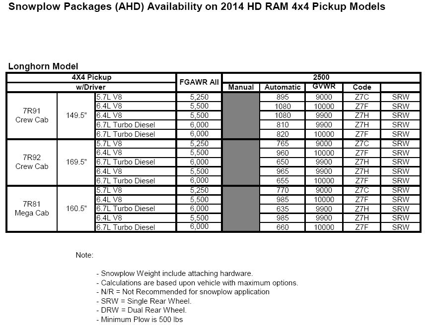
1 TRODUCTION The factoryinstalled Snowplow Preparation Groups (or their equivalent components) are recommended and listed for each vehicle. The normal warranty applies to Dodge Ram trucks that have after market snowplows installed in accordance with these guidelines. Maximum Vehicle Loading Requirements: Installation of snowplows and their mounting hardware may result in a vehicle weight distribution or a front axle loading which is detrimental to brake performance or which exceeds the front GAWR. The following load requirements are applicable: 1. The loaded vehicle, including all after market accessories, the snowplow system, passengers, and cargo, must not exceed the gross vehicle weight (GVW), front or rear gross axle weight (GAW) ratings specified on the Safety Compliance Certification label located in the driver s side door opening. 2. The empty truck with all permanently attached accessories and snowplow components must not exceed 62 percent of its total weight on the front axle to comply with FMVSS/CMVSR 105 Brake Certification. Permanently attached snowplow parts are those parts not easily removed when the blade is removed. The permanently attached parts are: subframe, hydraulic pump, hydraulic lift cylinder, lamps, wiring, snowplow controls, etc. If the front axle loading exceeds either 62 percent of the empty truck total weight, or the front GAWR, ballastcompensating weight must be securely attached at the rear of the truck to bring front axle weight within weight specifications as defined above. Notes for Heavy Duty Snowplows: At any time, the maximum number of occupants in the truck must not exceed two Under Any Circumstances, vehicles should NOT exceed GVWR (Gross Vehicle Weight Rating), Front or Rear GAWRs (Gross Axle Weight Ratings) Snowplow prep packages are NOT available with Sport (AAG) package Cargo capacity will be reduced by the addition of options. Ballast should be securely attached inside the box at 9 inches from the rear tailgate for pickups. The total weight of permanently attached hardware should not exceed 125 lbs. Max snowplow weight should not exceed values for models shown in this section. The snowplow weights shown in the charts on the next page are the manufacturer recommendations based on maximum vehicle option content. Other plow weight values may be possible, based on the specific capability of the vehicle being modified (actual weight, GVWR, front and rear GAWR). The maximum allowable plow weight can be determined by the dealer /supplier / manufacturer. In all cases, the loaded vehicle weight, including the snowplow system, all aftermarket accessories, driver, passengers, options, and cargo, must not exceed either the Gross Vehicle Weight (GVWR) or Gross Axle Weight (GAWR) ratings. The GVWR and GAWR weights are specified on the Safety Compliance Certification Label on the driver s side door opening. CHRYSLER GROUP LLC Safety Compliance Certification Label
2
3

4

5
6 ELECTRICAL CONSIDERATIONS HEADLAMPS Each headlamp bulb is independently Pulse Width Modulated (PWM) controlled by an electronic control module. This module also monitors each bulb to detect failures (i.e. bulb burned out) on both the high beam and low beam filaments. When this failure occurs, the LAMP telltale indicator in the instrument cluster will illuminate whenever the ignition is in the RUN position. The module also provides the DRL function when required and therefore there is no separate DRL controller. Therefore, the any aftermarket wiring kits should use the following guidelines: Disconnection of the OEM headlamps will be interpreted by the electronic module as a burned out bulb therefore; it is recommended that the aftermarket lamps utilize the OEM headlamp circuits. NOTE the aftermarket bulbs must draw no more current than the OEM bulbs (9007QL). Provide a means of allowing the customer to manually switch between the OEM headlamps and the aftermarket headlamps. Connection of both the OEM and aftermarket lamps at the same time will cause the control module to disable the circuit due to an overload condition and illuminate the LAMP indicator in the instrument cluster. Also, assure that the OEM headlamps cannot be inadvertently disabled when the aftermarket lamps are disconnected (i.e. when the snowplow is not on the vehicle). Do NOT splice the right and left headlamp circuits together. Connection of both lamps to the same circuit will cause the control module to disable the circuit due to an overload condition and illuminate the LAMP indicator in the instrument cluster. TURN LAMPS Each turn lamp front driver, front passenger, rear driver, and rear passenger is independently controlled by an electronic control module. This module also monitors each bulb to detect failures (i.e. bulb burned out). When this failure occurs the LAMP tell tale indicator in the instrument cluster will illuminate whenever the ignition is in the RUN position. In order to successfully connect the plows turn signal lamps to the vehicle s wiring the following must be done: Both L60 & L61 need to be spliced into in order to control a set of relays (please see attached drawing on page 5). These relays are necessary for proper function of the turn signals while the plow lamps are attached to the vehicle s electrical system. Failure to do so will cause the front turn signals to be inoperable or intermittent. NOTE: The electronic module is only capable of detecting bulb failure in the vehicles lamps. PARK LAMPS The vehicle park/tail/license/marker/tailgate lamps are partitioned into three subsets driver side, passenger side, and trailer tow connectors with the total vehicle load balanced between the driver and passenger side. Aftermarket wiring kits must have provisions that: Maintain separation between all three subsets. The preferred method for aftermarket park lamps is to use one of these circuits as a sense line to control a relay to activate aftermarket lamps. The relays power feed needs to be a fused battery feed provided by the kit If aftermarket park lamps need to be wired directly to the vehicle circuits. The load should be balanced between driver and passenger side, with neither side sourcing more than 2A of additional load current. The driver side circuit is L161, 20 gauge WT/YL wire see wiring schematics. The easiest place to find and splice into this circuit is in the harness bundle near the connection to the driver headlamp assembly The passenger side circuit is L160, 20 gauge WT/GY wire see wiring schematics. The easiest place to find and splice into this circuit is in the harness bundle near the connection to the passenger headlamp assembly IGNITION RUN FEED If required, the only location to obtain an ignition run feed is to splice into circuit F306. Circuit F gauge PK/YL is a dedicated Ignition Run feed to the Cigar Lighter. The best location to splice into F306 is right at the connection into the back of the Cigar Lighter. This connection can be accessed by removing the center stack trim piece which the Cigar Lighter is mounted into. There will be two wires going into the connector. Circuit F306 is the 18 The front driver circuit is L61, 18 gauge WT/LG The front passenger circuit is L60, 18 gauge WT/TN
7 gauge PK/YL wire. The other wire will be (Z736) BK/YL tracer. The spliced in aftermarket wire should be a minimum 18 gauge high temperature rated wire due to the 20A fuse for the Cigar lighter. The load placed on the aftermarket circuit should not exceed 2A. Exceeding 2A will potentially blow the Cigar Lighter fuse when activating the Cigar lighter and the aftermarket load simultaneously. Note: Circuit F306 is an Ignition Run and ACCESSORY feed, meaning it will be hot with the ignition key in the Run position and also the Accessory position. Note: If more than a 2A ignition feed is required, then the aftermarket application will have to add an external relay, with appropriate battery fusing and use the recommended F306 circuit to turn the relay on and off. Note: There is no other acceptable place to find a vehicle Ignition Run source, in cab or underhood.
8
Recreational Vehicle Towing Guide
 Recreational Vehicle Towing Guide TABLE OF CONTENTS HOW TO DETERMINE THE GROSS VEHICLE WEIGHT RATING FOR RECREATIONAL VEHICLES Terms and Definitions... 2 Conversion... 3 Net Weight... 4 Manufacturer Gross
CONSUMER INFORMATION TRUCK-CAMPER LOADING
 2015 MODEL YEAR GENERAL MOTORS INFORMATION REGARDING CONSUMER INFORMATION TRUCK-CAMPER LOADING PUBLISHED JANUARY 2014 Page 1 2015 MODEL YEAR GENERAL MOTORS TRUCKS CONSUMER INFORMATION TRUCK-CAMPER LOADING
Trailblazer, Envoy, Rainier, Ascender
 6. After removing the trim plate bezel simply remove the four ¼ screws holding the instrument cluster in place. Pull the cluster out and unplug the single wiring harness connection in the back. Trailblazer,
Light-Duty Vehicle Purchase Approval Form
 Light-Duty Vehicle Purchase Approval Form Attachment II Requestor Name: Date: (As of date of application for vehicle to be replaced) Replacement (R) / New (N): (Enter R or N) Mileage (km): Department:
INSTALLATION MANUAL TRAILER LIGHTS CONTROLLER MODULE TYPE MP2-D1 / MP2-D2
 INSTALLATION MANUAL TRAILER LIGHTS CONTROLLER MODULE TYPE MP2-D1 / MP2-D2 QUASAR ELECTRONICS ul. Cieslewskich 25K 03-017 Warsaw tel. +48 (022) 678-68-96, 678-64-50 http://www.quasarelectronics.pl e-mail:
1978-83 Malibu 1978-87 Monte Carlo 1978-87 El Camino
 Important facts about this kit. 1. The dash panel used in this picture is used by permission of Covan's Classic. 2. This kit requires some modification to your original under dash wiring harness. It is
Subaru Reference. This reference contains the following information: connector pinouts. connector pinouts
 Subject: Source: 1993 2010 Impreza, WRX, and Sti and 2002 07 Outback Sport ABS wiring diagrams, harness routing, and connector locations and pinouts Subaru service manuals This reference contains the following
BODY ELECTRICAL MAZDA
 BODY ELECTRICAL ASSIGNMENT WORKSHEETS Version 1.3 MAZDA ELECTRICAL WIRING DIAGRAM WORKBOOK http://www.autoshop101.com Developed by Kevin R. Sullivan All rights reserved. MAZDA Table of Contents Wiring
Schematic - 379 Model Family Electrical P94-6023 C 01
 Schematic - 379 Model Family Electrical P94-6023 C 01 SH NO. TITLE 1) INDEX 2) ARCHITECTURE 85) ENGINE - CUM ISX ( BJ SERVICES ) ( CONTINUED ) 3) LOCATION OF MAJOR COMPONENTS 86) ENGINE ECU POWER 4) LOCATION
VEHICLE THEFT/SECURITY SYSTEMS
 DN VEHICLE THEFT/SECURITY SYSTEMS 8Q - 1 VEHICLE THEFT/SECURITY SYSTEMS TABLE OF CONTENTS page GENERAL INFORMATION INTRODUCTION...1 VEHICLE THEFT SECURITY SYSTEM....1 ENABLING...1 ARMING...1 DISARMING...2
INSTALLATION INSTRUCTIONS
 INSTALLATION INSTRUCTIONS Electric Vacuum Pump Kit 28146 Thank you for choosing STAINLESS STEEL BRAKES CORPORATION for your braking needs. Pleases take the time to read and carefully follow these instructions
PARTS & INSTALLATION INSTRUCTIONS MEYER SNOW PLOW LIGHTS
 Form 1-696 R1 January, 2003 PARTS & INSTALLATION INSTRUCTIONS MEYER SNOW PLOW LIGHTS PARTS LIST ITEM PART NO. QTY. DESCRIPTION 07033 1 SNOW PLOW LIGHT CARTON 1 07034 1 Snow Plow Light, Pass. Side (No Hardware)
Hydraulic Power Brake (HPB) Catalog
 Catalog") PB-06107 Revised 03/11 Hydraulic Power Brake (HPB) Catalog Page Accumulator 4 Diagnostic and Test Equipment 10 Electronic Control Unit (ECU) 4 HCU Accessories 6 HCU Quick Reference 3 HCU Reservior 4 Hydraulic
PB-06107 Revised 03/11 Hydraulic Power Brake (HPB) Catalog Page Accumulator 4 Diagnostic and Test Equipment 10 Electronic Control Unit (ECU) 4 HCU Accessories 6 HCU Quick Reference 3 HCU Reservior 4 Hydraulic
BODY ELECTRICAL TOYOTA ELECTRICAL WIRING DIAGRAM WORKBOOK. ASSIGNMENT Version 1.8 WORKSHEETS. http://www.autoshop101.com
 BODY ELECTRICAL ASSIGNMENT Version 1.8 WORKSHEETS TOYOTA ELECTRICAL WIRING DIAGRAM WORKBOOK http://www.autoshop101.com Developed by Kevin R. Sullivan All Rights Reserved TOYOTA Table of Contents Wiring
by Myles H. Kitchen M.H. KITCHEN & ASSOCIATES www.auto-electronic.com (2002 X5 4.4 owner) March 2, 2004
 March 2, 2004") INSTALLING THE TEKONSHA PRODIGY ELECTRIC TRAILER BRAKE CONTROL IN THE BMW X5 by Myles H. Kitchen M.H. KITCHEN & ASSOCIATES www.auto-electronic.com (2002 X5 4.4 owner) March 2, 2004 INTRODUCTION The 2000
INSTALLING THE TEKONSHA PRODIGY ELECTRIC TRAILER BRAKE CONTROL IN THE BMW X5 by Myles H. Kitchen M.H. KITCHEN & ASSOCIATES www.auto-electronic.com (2002 X5 4.4 owner) March 2, 2004 INTRODUCTION The 2000
Installation Instructions
 Installation Instructions Page 1 of 16 January 2008 Equipment Parts, Trailer Hitch Ver 3.0 Accessory Development SUBJECT TRAILER HITCH KIT (US Only) - P/N 71 60 0 413 359 MODEL X5 (E70): Select Vehicle
INSTALLATION INSTRUCTIONS
 Rear Vision System Aftermarket and Factory 5.0, 8.4 and 6.1 MyGig Touch Screen Display (Factory Display requires Chrysler/Dodge dealer to activate) 2009 Current* Dodge Ram (Kit part number 1009-6503) *NOTE:
Mazda CX7 2007-09 99-7508
 INSTALLATION INSTRUCTIONS FOR PART 99-7508 APPLICATIONS Mazda CX7 2007-09 99-7508 KIT FEATURES DIN Radio Provision with Pocket ISO Mount Radio Provision with Pocket Double DIN Mount Radio Provision Stacked
510351 92970196 instruction rev 0.0 11/13/2012
 INSTRUMENT LUSTER ISNET AESSORY NETOR INITION Sheet 2 FLOOR IMMER WIPER PA AS ROUN LEFT AN RIT AN ELETRI SPEEO ROUN ORN RELAY TURN SINAL PARIN BRAE NEUTRAL SAFETY EALIT BRAE RAIO IARETTE LITER BA UP INSTALLIN
INSTRUCTIONS FOR THE INSTALLATION AND OPERATION OF ACTIVATOR II
 INSTRUCTIONS FOR THE INSTALLATION AND OPERATION OF ACTIVATOR II ELECTRONIC TRAILER BRAKE CONTROL 5500 FOR 2, 4, 6 & 8 BRAKE SYSTEMS IMPORTANT: READ AND FOLLOW THESE INSTRUCTIONS CAREFULLY. KEEP THESE INSTRUCTIONS
Emergency Response Guide
 Emergency Response Guide Honda Natural Gas Vehicles This publilcation covers these Civic Natural Gas Models: 1998-2000 2001-2005 2006-2011 2012 Prepared for Fire Service, Law Enforcement, Emergency Medical,
Fitting/Installation Guide - UNIVERSAL
 ATTENTION: This wiring information is being provided free of charge and on an as is basis, without any representation or warranty. It is your responsibility to verify any circuit before interfacing with
INSTALLATION GUIDE OWNER S GUIDE
 INSTALLATION GUIDE OWNER S GUIDE KEYLESS ENTRY MODELS KE100 / KE150 / 1702 CONTENTS System Features... 1 System Components... 1 Technical Assistance... 1 Before You Begin... 1 Precautions... 1-2 Making
6 LOADING AND UNLOADING A FLATBED
 6 LOADING AND UNLOADING A FLATBED TRAILER Improper trailer loading causes many accidents and deaths. To safely load a trailer, you must consider: Overall load weight; Load weight distribution; Proper tongue
Basic manual: Contents ELECTRONICALLY CONTROLLED HYDRAULIC SYSTEMS
 TECHNICAL NOTE Edition Anglaise 77 11 205 445 JUNE 1999 Type 3239A Service 0422 Sub-section JE0 X BOSCH 5.3 ABS WITH SPEED INFORMATION FUNCTION Engine: Gearbox: XXX XXX Basic manual: N.T. 3034A This note
Bulb Replacement REPLACING BULBS WARNING
 Bulb Replacement REPLACING BULBS Check the operation of all exterior lamps before you drive the vehicle. Caution: Before attempting to replace a bulb, ensure that both the affected lamp and the vehicle's
Emergency Response Guide
 Emergency Response Guide Honda CNG Vehicle Prepared for Fire Service, Law Enforcement, Emergency Medical, and Professional Towing Personnel by American Honda Motor Co., Inc. Contents Key Components 1
Wire(s) Won t Fit (Kit s Wiring Harness)
 Won t Fit (Kit s Wiring Harness)") HID Conversion Kit General Troubleshooting Table of Contents 1. Bulb(s) Won t Fit 2. Wire(s) Won t Fit (For Kit s Wiring Harness) 3. One Side Consistently Doesn t Light Up 4. Both Sides Consistently Don
HID Conversion Kit General Troubleshooting Table of Contents 1. Bulb(s) Won t Fit 2. Wire(s) Won t Fit (For Kit s Wiring Harness) 3. One Side Consistently Doesn t Light Up 4. Both Sides Consistently Don
Installation Instructions
 520 Installation Instructions Thank you very much for purchasing PIAA product. Please read this entire manual before installation and use of this product. For Installers Please give this Installation Manual
ELECTRICAL WIRING (R.H. DRIVE VEHICLES)
") C-1 ELECTRICAL WIRING (R.H. DRIVE VEHICLES) CONTENTS GENERAL.......................... 3 WIRING HARNESS CONFIGURATION DIAGRAMS......................... 4 ENGINE COMPARTMENT................ 4 DASH PANEL...........................
C-1 ELECTRICAL WIRING (R.H. DRIVE VEHICLES) CONTENTS GENERAL.......................... 3 WIRING HARNESS CONFIGURATION DIAGRAMS......................... 4 ENGINE COMPARTMENT................ 4 DASH PANEL...........................
2004 CAMPER/TRAILER TOWING
 INDEX 2004 CAMPER/TRAILER TOWING Subject Page Number Camper Information 2-4 Trailer Towing Tips 5-9 Trailer Towing Weight Definitions 10-11 Trailer Towing Applications Trailer Weights/Frontal Area Considerations/
E30 Fog Light Wiring Instructions Conversions Allowing for Independent Fog Light Operation in Sealed Beam and Ellipsoid Style Headlight Systems
 E30 Fog Light Wiring Instructions X Mon Revision A 26 April, 2007 This document details the steps required to convert the headlight dependent fog lights of the E30 chassis BMW to an array of user configurable
Class 5 to 7 Truck and Bus Hydraulic Brake System
 Class 5 to 7 Truck and Bus Hydraulic Brake System Diagnostic Guide 1st Edition * 5+0 Important Service tes The information in this publication was current at the time of printing. The information presented
1970-72 Chevelle. 1970-72 Chevelle. (500645) Gauge Cluster Kit Installation Instructions. (500645) Gauge Cluster Kit Installation Instructions
 Gauge Cluster Kit Installation Instructions. (500645) Gauge Cluster Kit Installation Instructions") 1970-72 Chevelle (500645) Gauge Cluster Kit Installation Instructions 1970-72 Chevelle (500645) Gauge Cluster Kit Installation Instructions STEP 1: There are 4 small gauges. This is a photo of the bare
1970-72 Chevelle (500645) Gauge Cluster Kit Installation Instructions 1970-72 Chevelle (500645) Gauge Cluster Kit Installation Instructions STEP 1: There are 4 small gauges. This is a photo of the bare
PUSH BUTTON START INSTALLATION MANUAL
 PUSH BUTTON START INSTALLATION MANUAL ALTHOUGH THIS PRODUCT HAS BEEN THOROUGHLY TESTED KPIERSON TECHNOLOGIES ASSUMES NO RESPONSIBILITY FOR ANY DAMAGE THAT MAY RESULT BY THE INSTALLATION OF THIS PRODUCT.
Wiring diagrams 14 1. Component key for wiring diagrams 1 to 29 Note: Not all the items listed will be fitted to all models
 Wiring diagrams 14 1 Component key for wiring diagrams 1 to 29 Note: Not all the items listed will be fitted to all models No Description 00200 Alternator with built-in regulator 00500 Battery 01001 Starter
Before installation it is important to know what parts you have and what the capabilities of these parts are.
 INSTALLATION GUIDE Before installation it is important to know what parts you have and what the capabilities of these parts are. The Recon XZT is the smallest and most powerful gauge of its kind. With
CMD-8000 rev. A COMMANDER SERIES REMOTE CONTROL ENTRY SYSTEM
 INTRODUCTION CMD-8000 rev. A COMMANDER SERIES REMOTE CONTROL ENTRY SYSTEM Thank you for purchasing the CMD-8000 Commander from Dakota Digital. This, along with many other products that Dakota Digital has
Auxiliary HVAC RAM ProMaster. Standard Tie-in Extreme Climate System
 Auxiliary HVAC RAM ProMaster Standard Tie-in Extreme Climate System Auxiliary HVAC High performance aftermarket heating and cooling systems engineered for vehicle specific platforms that minimize install
Left Hand Limit Switch. Housing. Left Hand. Connections. Motor Connector BROWN PURPLE GRAY BLACK DARK BLUE BLACK BROWN BROWN LIGHT BLUE.
 LIGHT BLUE GRAY PURPLE Circuit Breaker Intput Circuit Breaker Output #1 Relay Left Hand Limit Switch Housing Left Hand Motor Connector Right Hand Limit Switch on Radiator Support Right Hand Limit Switch
Walbro 255lph Inline Fuel Pump Install Procedure
 Walbro 255lph Inline Fuel Pump Install Procedure Note: Instructions are based on a single in tank pump with under car OEM VW filter. Total install time for a qualified technician is approximately 2 hrs.
Get your lights right. What you need to know about fitting and using additional vehicle lighting
 Get your lights right What you need to know about fitting and using additional vehicle lighting NZ Transport Agency Get your lights right 2012 NZ Transport Agency 1 GET YOUR LIGHTS RIGHT CONTENTS WHAT
GENUINE PARTS INSTALLATION INSTRUCTIONS
 GENUINE PARTS INSTALLATION INSTRUCTIONS DESCRIPTION: Illuminated Kick Plate APPLICATION: Rogue (2011) PART NUMBER: 999G6 GX010 KIT CONTENTS: Item A B C G H QTY 1 1 1 D 1 E 1 F 3 15 6 Description Kick Plate,
BMW X5 Tail Lamp Assembly Repair. By Myles H. Kitchen M.H. KITCHEN & ASSOCIATES www.auto-electronic.com Email: MHKitchen@aol.com
 BMW X5 Tail Lamp Assembly Repair By Myles H. Kitchen M.H. KITCHEN & ASSOCIATES www.auto-electronic.com Email: MHKitchen@aol.com INTRODUCTION A common problem experienced by BMW X5 owners is a Check Rear
TOYOTA Tundra 2007 - BACK-UP CAMERA SYSTEM Preparation
 Preparation Part Number(s): PT233-34070, PT923-35070-11, PT923-35070-43 NOTE: Part number of this accessory may not be the same as part number shown. Back Up Monitor Kit Contents PT923-35070-11 / PT923-35070-43
R02GA. July 31, 2002. Dear Blue Bird Owner:
 R02GA July 31, 2002 Dear Blue Bird Owner: This notice is sent to you in accordance with the requirements of the National Traffic and Motor Vehicle Safety Act. Blue Bird Body Company has determined that
5 Mechanisms and accessories
 5 Mechanisms and accessories 51A SIDE OPENING ELEMENT MECHANISMS 52A NON-SIDE OPENING ELEMENT MECHANISMS 54A WINDOWS 55A EXTERIOR PROTECTION 56A EXTERIOR EQUIPMENT 57A INTERIOR EQUIPMENT X79 NOVEMBER 2009
EXTENDED-WIRE HANDLEBAR SWITCH KITS
 -J03396 REV. 2010-02-11 EXTENDED-WIRE HANDLEBAR SWITCH KITS ENERAL Kit Numbers 70246-10, 70318-10 Models Neither of these kits is compatible with cruise control-equipped 2007 or earlier models. Kit 70246-10
Introduction to Electronic Signals
 Introduction to Electronic Signals Oscilloscope An oscilloscope displays voltage changes over time. Use an oscilloscope to view analog and digital signals when required during circuit diagnosis. Fig. 6-01
For customers Please forward this manual to the next owner.
 PKI-0047 Installation Manual for LED Performance Bulbs (Type H8/H9/H11/H16) Thank you very much for purchasing PIAA product. Read this instruction manual thoroughly for proper use of the product. After
The Vehicle Commissioning Report and the Vehicle Equipment Registration are designed to ensure vehicles and equipment are:
 Vehicle Practice Practice: Reference: 1 of 8 1.0 INTRODUCTION The Vehicle Commissioning Report and the Vehicle Equipment Registration are designed to ensure vehicles and equipment are: 1. Entered on Fleet
Electrical/electronic components and installation locations
 Volkswagen Passat B5 - Electrical/electronic components and installation locations Page 1 / 24 45-3 Electrical/electronic components and installation locations ABS/EDL/ASR Bosch 5.3 ABS hydraulic unit
Back-Up Camera Installation Guide
 Hz Hz In This Guide: Back-up camera installation requires connecting power wiring to the existing reverse lighting circuit and adding a chassis ground, as well as routing a video signal cable to the front
1999-2010 GENERAL MOTORS 3/4 &1 TON RT3 UNDERCARRIAGE MOUNTING INSTRUCTIONS (PART NO. LTA04767B)
") 1999-010 GENERAL MOTORS 3/4 &1 TON MOUNTING INSTRUCTIONS (PART NO. LTA04767B) MSC04380-8 WARNING Many newer trucks are now equipped with air bags. DO NOT under any circumstances disable, remove or relocate
1999-010 GENERAL MOTORS 3/4 &1 TON MOUNTING INSTRUCTIONS (PART NO. LTA04767B) MSC04380-8 WARNING Many newer trucks are now equipped with air bags. DO NOT under any circumstances disable, remove or relocate
VEHICLE THEFT/SECURITY SYSTEM
 PL VEHICLE THEFT/SECURITY SYSTEM 8Q - 1 VEHICLE THEFT/SECURITY SYSTEM TABLE OF CONTENTS page DESCRIPTION AND OPERATION INTRODUCTION...1 VEHICLE THEFT/SECURITY SYSTEM (VTSS)... 1 (SKIS)... 2 SENTRY KEY
2. Remove rear cover of head lamp if bulbs are covered/sealed within the housings, and remove halogen bulb carefully.
 These instructions are designed to address most general installation procedures across vehicles and should not be considered vehicle make, model or year specific. Please contact the vendor directly for
HID H4 BI-XENON FITTING GUIDE. Carefully read the following notes before starting work.
 HID H4 BI-XENON FITTING GUIDE Carefully read the following notes before starting work. WARNING! This HID kit should only be installed by someone competent in vehicle wiring and electrics. Incorrect fitment
AEROMOTIVE Part # 16302 INSTALLATION INSTRUCTIONS
 AEROMOTIVE Part # 16302 INSTALLATION INSTRUCTIONS CAUTION: Installation of this product requires detailed knowledge of automotive systems and repair procedures. We recommend that this installation be carried
2010 Ford F-150 THE 2010 F-150. America s best-selling line of trucks for 32 years running is clearly a leader in so many ways!
 2010 Ford F-150 Click to download a complete RV & Trailer Towing Guide. THE 2010 F-150 America s best-selling line of trucks for 32 years running is clearly a leader in so many ways! From design to manufacturing
Equipment Listing 3C63RRGL7EG137843 STANDARD EQUIPMENT. Monotone Paint. 730 Amp Maintenance Free Battery. Electronic Stability Control
 Equipment Listing VIN Vehicle Description 3C63RRGL7EG137843 2014 RAM 3500 ST 4X4 STANDARD EQUIPMENT Monotone Paint 730 Amp Maintenance Free Battery Electronic Stability Control Anti-Lock 4-Wheel Disc Brakes
Xenon HID Lighting System
 Automotive Safety Systems User Installation Manual Preface Specifications Thank you for purchasing NOVABLUE Xenon H.I.D. (High Intensity Discharge) vehicle lighting systems. Before installing this product,
Supplementary restraints system
 Supplementary restraints system PRINCIPLE OF OPERATION High speed impacts may cause serious injury or death irrespective of safety features fitted to the vehicle. Always drive with caution and consideration
Now Available With. Technical Support. Temperature Monitor & Alert Unit For K9 Police Vehicles M852-15 and M852-20 with Alpha
 Now Available With Temperature Monitor & Alert Unit For K9 Police Vehicles M2-15 and M2-20 with Alpha Alpha Check will remind you to check the safety of your K9 partner. CoolGuard Temp Probe Technical
Alternative Fuel Sedans Section 1: Line Item Number (Mandatory)
") Sedans 1-11-23-22 Clawson Honda of Fresno Coalinga Motors Coalinga Motors Line Item No. Sacramento 1 Sacramento 2 Sacramento 3 Sacramento Line Item No. Los Angeles 19 Los Angeles 20 Los Angeles 21 Los
Sedans 1-11-23-22 Clawson Honda of Fresno Coalinga Motors Coalinga Motors Line Item No. Sacramento 1 Sacramento 2 Sacramento 3 Sacramento Line Item No. Los Angeles 19 Los Angeles 20 Los Angeles 21 Los
THE CARROLL COUNTY BUCKWILD TRUCK & TRACTOR CLASSIC SATURDAY APRIL 30 TH
 THE CARROLL COUNTY BUCKWILD TRUCK & TRACTOR CLASSIC SATURDAY APRIL 30 TH TRUCK DRAG RACING 2:00 PM TRUCK PULL 5:300 PM Admission $12.00/Day $20.00/Weekend Pass FOOD & BEER GARDEN AVAILABLE ON THE GROUNDS
MOTOR VEHICLE MECHANIC REPAIR CATEGORIES
 Chapter 8: Motor Vehicle Mechanic Repair Categories Page 1 CHAPTER 8 MOTOR VEHICLE MECHANIC REPAIR CATEGORIES Section 8-1 REQUIREMENT Section 10 of the Motor Vehicle Service and Repair Act (MCL 257.1310)
1969 DODGE CORONET Two panel Sequential LED Taillight kit installation guide
 1969 DODGE CORONET Two panel Sequential LED Taillight kit installation guide Kit Contents: 2 LED panels 4 rubber grommets 1 power wire with t-tap 1 driver side LED harness, 24 1 passenger side LED harness,
Make Before Break -- Measuring Parasitic Currents by Wade Nelson
 Make Before Break -- Measuring Parasitic Currents by Wade Nelson The rule of thumb is, Anything under 30mA is acceptable, anything over 50mA indicates an excessive draw. (Below) Nobody likes blowing DMM
TRAIL CHARGER BASED CHARGING SOLUTIONS
 TRAIL CHARGER BASED CHARGING SOLUTIONS The Challenge Keeping Auxiliary Liftgate Batteries Charged The performance and proper function of a liftgate depends on an adequately charged auxiliary battery pack.
BILLET HEADLAMP WITH SHORT/TALL MOUNTS
 -J099 REV. 00-0- BILLET HEADLAMP WITH SHORT/TALL MOUNTS GENERAL Kit Number 9-0, 9-0 Models Kit 9-0 is a -/ inch headlamp and kit 9-0 is a -/ inch headlamp. Both kits will fit the models listed in Table.
The Child Reminder System Installation Manual
 The Child Reminder System Installation Manual Revised June, 2006 Detailed installation information can be found at www.childreminder.com. Get through your installation quickly and easily by calling 1-888-330-6786
Diagnosing Body Electrical Problems
 Diagnosing Body Electrical Problems Learning Objectives: 1. Examine the diagnostic strategies for: Open Circuit Problems High Resistance Problems Unwanted Parasitic Load Problems Short to ground Problems
Volkswagen Jetta, Golf, GTI 1999, 2000 Brake System 47 Brakes - Hydraulic Components (Page GR-47)
") 47 Brakes - Hydraulic Components (Page GR-47) FS III front brake calipers, servicing Front brake caliper piston, removing and installing FN 3 front brake calipers, servicing Front caliper piston, removing
47 Brakes - Hydraulic Components (Page GR-47) FS III front brake calipers, servicing Front brake caliper piston, removing and installing FN 3 front brake calipers, servicing Front caliper piston, removing
ACCUMULATOR INSTALLATION
 7001-7 ACCUMULATOR INSTALLATION BRAKE ACCUMULATORS I 308L93 Rae 7-59710 Issued 6-93 Printed in U.S.A 7001-8 Removal ACCUMULATOR VALVE 1. Park the machine on a level surface and lower the. loader bucket
TECHNICAL SPECIFICATIONS - HI-RAIL INSPECTION TRUCK DESCRIPTION
 TECHNICAL SPECIFICATIONS - HI-RAIL INSPECTION TRUCK DESCRIPTION This specification describes a Heavy Duty (4X4) Four Wheel Drive Crew Cab Pickup Truck with Lift Gate & Wide Side with 8-Foot Bed. Under
Question: How Do I Install a Back of Cab Remote Power Module Kit and Switch Pack?
 Question: How Do I Install a Back of Cab Remote Power Module Kit and Switch Pack? nswer: Purchase a remote and switch pack kit, Part Number 008C9 from International Service Parts. Place all parts on a
2010 Ford F-250, F-350 & F-450 SUPER DUTY PICKUP. Rely on Proven Strength. Natural BORN LEADERS. Hitch Receiver is Standard (c)
") 2010 Ford F-250, F-350 & F-450 SUPER DUTY PICKUP Click to download a complete RV & Trailer Towing Guide. BEST-IN-CLASS 5th Wheel Towing UP TO 24,600 LBS. (b) BEST-IN-CLASS Conventional Towing UP TO 16,000
2010 Ford F-250, F-350 & F-450 SUPER DUTY PICKUP Click to download a complete RV & Trailer Towing Guide. BEST-IN-CLASS 5th Wheel Towing UP TO 24,600 LBS. (b) BEST-IN-CLASS Conventional Towing UP TO 16,000
INSTRUMENT PANEL. 1995 Volvo 850 DESCRIPTION & OPERATION. 1995-96 ACCESSORIES & EQUIPMENT Volvo Instrument Panels
 INSTRUMENT PANEL 1995 Volvo 850 1995-96 ACCESSORIES & EQUIPMENT Volvo Instrument Panels 850 WARNING: When working around steering column and before performing repairs, disconnect and shield battery ground
Stop Alert Flasher with G-Force sensor
 Stop Alert Flasher with G-Force sensor Stop Alert module creates brake light flashing effect to catch attention of the drivers behind to avoid dangerous rear end collision. The flasher module is a state
«Filter-MB» Technical Manual
 Technical Manual www.tec-electronics.ru/en/ Unit Description... 2 Unit connection... 2 Table 1. Unit port outputs assignment... 3 Conenction recomendations... 3 Table 2. Technical data and operation conditions...
E&P HYDRAULICS Remote control EPRC-01 Level System Camper
 USER S GUIDE E&P HYDRAULICS Remote control EPRC-01 Level System Camper 1 Copyright 2012, E&P Hydraulics This manual is copyrighted, with all rights reserved. Under the copyright laws, this may not, in
SVE BULLETIN. 2005-2007 F-Series Super Duty Upfitter Switches
 005 00 FSeries Super Duty Switches See QR for Model Year 008 or Later at Link Below https://www.fleet.ford.com/truckbbas/nonhtml/qr.pdf Models Affected All 005 Model Year F50/350/450/550. Purpose To utilize
2007 W-SERIES (CHEVROLET & GMC) N-SERIES (ISUZU) 250 NPR/W3500, NPR HD/W4500, NQR/W5500, NRR/W5500-HD Diesel Electrical Symbols
 N-SERIES (ISUZU) 250 NPR/W3500, NPR HD/W4500, NQR/W5500, NRR/W5500-HD Diesel Electrical Symbols") 2007 W-SERIES (CHEVROLET & GMC) N-SERIES (ISUZU) 250 NPR/W3500, NPR HD/W4500, NQR/W5500, NRR/W5500-HD Diesel Electrical Symbols Symbol Meaning Symbol Meaning Symbol Meaning Fuse Electronic Parts Coil (Inductor),
2007 W-SERIES (CHEVROLET & GMC) N-SERIES (ISUZU) 250 NPR/W3500, NPR HD/W4500, NQR/W5500, NRR/W5500-HD Diesel Electrical Symbols Symbol Meaning Symbol Meaning Symbol Meaning Fuse Electronic Parts Coil (Inductor),
Headlight switch. The daytime running. lights) turn on.
 turn on.") Headlight switch The headlights can be operated manually or automatically. U.S.A. Canada The daytime running lights turn on The side marker, parking (vehicles with halogen headlights), daytime running
Headlight switch The headlights can be operated manually or automatically. U.S.A. Canada The daytime running lights turn on The side marker, parking (vehicles with halogen headlights), daytime running
This section deals with mandatory and optional equipment for your vehicle as well as suggestions for safer road use.
 3. EQUIPMENT This section deals with mandatory and optional equipment for your vehicle as well as suggestions for safer road use. 3.1 Lights No person shall drive a vehicle on a highway at nighttime or
Mazda CX7 2010-up 99-7520B
 INSTALLATION INSTRUCTIONS FOR PART 99-7520B APPLICATIONS Mazda CX7 2010-up 99-7520B KIT FEATURES DIN radio provision with pocket ISO radio provision with pocket Double DIN radio provision Painted matte
3. Commercial Trailer Lighting Requirements Federal Motor Carrier Safety Regulations (FMCSR) 49 CFR, Subpart B Of FMCSR Part 393
 49 CFR, Subpart B Of FMCSR Part 393") FMCSR 393.9.26 3. Commercial Trailer Lighting Requirements Federal Motor Carrier Safety Regulations (FMCSR) 49 CFR, Subpart B Of FMCSR Part 393 Lighting Devices, Reflectors, and Electrical Equipment 393.9
FMCSR 393.9.26 3. Commercial Trailer Lighting Requirements Federal Motor Carrier Safety Regulations (FMCSR) 49 CFR, Subpart B Of FMCSR Part 393 Lighting Devices, Reflectors, and Electrical Equipment 393.9
INTERACTIVE DISTANCE LEARNING ANTI-LOCK BRAKE SPECIALIST: KELSEY HAYES REAR WHEEL ANTI-LOCK BRAKING SYSTEMS (RWAL/RABS)
") INTERACTIVE DISTANCE LEARNING ANTI-LOCK BRAKE SPECIALIST: KELSEY HAYES REAR WHEEL ANTI-LOCK BRAKING SYSTEMS (RWAL/RABS) LEARNING GUIDE CARS KNOWLEDGE NETWORK 6 9120 Leslie Street Richmond Hill, ON L4B
INTERACTIVE DISTANCE LEARNING ANTI-LOCK BRAKE SPECIALIST: KELSEY HAYES REAR WHEEL ANTI-LOCK BRAKING SYSTEMS (RWAL/RABS) LEARNING GUIDE CARS KNOWLEDGE NETWORK 6 9120 Leslie Street Richmond Hill, ON L4B
Chapter 5. Components, Symbols, and Circuitry of Air-Conditioning Wiring Diagrams
 Chapter 5 Components, Symbols, and Circuitry of Air-Conditioning Wiring Diagrams Objectives Upon completion of this course, you will be able to: Explain what electrical loads are and their general purpose
CAN BUS INTERFACE. Module Information
 Part no: CB-1 The CAN Bus interface is designed to provide a vehicle speed signal for vehicles using a CAN Bus system. It is programmed to automatically detect the vehicle type and it will give a frequency
Signature and ISX CM870 Electronics
 Signature and ISX CM870 Electronics Cummins West Training Center System Description General Information The Signature and ISX CM870 engine control system is an electronically operated fuel control system
Technical Guide 08/15/14
 Technical Guide 08/15/14 1 Table of Contents Contact information.3 Identifying your system..4-8 Model Number Serial number location Parts of your fuel system..9-14 Fuel pump diagram Wire harness schematics
E30 Headlight Wiring Instructions Converting Sealed Beam Systems to Ellipsoid/European Style Headlight Systems Utilizing Single Filament Bulbs
 E30 Headlight Wiring Instructions Converting Sealed Beam Systems to Ellipsoid/European Style Headlight Systems Utilizing Single Filament Bulbs X Mon This document details the steps required to converting
Networkfleet 3500 Product Line Installation Guide
 Networkfleet 3500 Product Line Installation Guide Light/Medium Duty (L3500) Heavy Duty (H3500) Universal (U3500) www.networkcar.com/fleet Customer Care: (866) 227-7323 customercare@networkcar.com Table
SKYPATROL TT8750. Installer GUIDE. SKYPATROL highly recommends that a certified professional technician install the unit into your asset.
 SKYPATROL TT8750 Installer GUIDE SKYPATROL highly recommends that a certified professional technician install the unit into your asset. BE SURE TO REGISTER YOUR DEVICE ON LINE PRIOR TO HAVING IT INSTALLED
INSTRUCTION MANUAL FOR RECREATIONAL REFRIGERATOR/FREEZER MODEL
 INSTRUCTION MANUAL FOR RECREATIONAL REFRIGERATOR/FREEZER MODEL 15-LITER, 20-LITER, 35-LITER, 45-LITER, 60-LITER & 100-LITER SECTION 1 Basic Operation SECTION 2 Cleaning and Storing SECTION 3 Basic Trouble
How To Power A 12 Volt Relay On A Car Or Truck
 Relay modification for older bikes Please read this in conjunction with the schematics at the end. All the options are shown, but you can opt to do any one or more as you wish. The electrical connections
Sno-Way Snow Plows & Spreaders Frequently Asked Questions
 Blade Skins What can I use to clean my poly blade? Sno-Way recommends using soap and water or isopropyl alcohol. Are there products I should not use to clean poly? Abrasive or highly alkaline cleaners,
Diagnostic Fault Codes For Cummins Engines
 Section - Diagnostic Fault Codes For Cummins Engines Applies to Engine Models T, T, QSL T, QSM, QS, QSK9, QSK, QST, QSK//8 Note: These fault codes are current at date of publication. Always refer to engine
ENACTED BY LEGISLATURE: MAY 20, 2002 CITE AS: 6 HCC 8-16. 1. Authority. See basic document (Occupational Safety and Health Program Act).
.") HO-CHUNK NATION CODE (HCC) TITLE 6 PERSONNEL, EMPLOYMENT AND LABOR CODE SECTION 8 OCCUPATIONAL SAFETY AND HEALTH PROGRAM ACT OF 2002 SUBSECTION 16 FLEET SAFETY ENACTED BY LEGISLATURE: MAY 20, 2002 CITE
HO-CHUNK NATION CODE (HCC) TITLE 6 PERSONNEL, EMPLOYMENT AND LABOR CODE SECTION 8 OCCUPATIONAL SAFETY AND HEALTH PROGRAM ACT OF 2002 SUBSECTION 16 FLEET SAFETY ENACTED BY LEGISLATURE: MAY 20, 2002 CITE