Tailgates By THIEMAN TT-15 OWNERS MANUAL/PARTS LIST SHOWN WITH OPTIONAL 2 PC. ALUMINUM PLATFORM AND LIGHT KIT IMPORTANT! KEEP IN VEHICLE!
|
|
|
- Barrie Freeman
- 7 years ago
- Views:
Transcription
1 TM TOPLIFTER Tailgates By THIEMAN TT-15 OWNERS MANUAL/PARTS LIST SHOWN WITH OPTIONAL 2 PC. ALUMINUM PLATFORM AND LIGHT KIT! IMPORTANT! KEEP IN VEHICLE! PLEASE READ AND UNDERSTAND THE CONTENTS OF THIS MANUAL BEFORE OPERATING THE EQUIPMENT. NTEA T H E A S S O C I A T I O N F O R T H E W O R K T R U C K I N D U S T R Y M E M B E R HIEMAN TAILGATES, INC. 600 East Wayne Street Celina, Ohio Phone: Fax:

2 TABLE OF CONTENTS WARNINGS OPERATING INSTRUCTIONS MAINTENANCE GUIDE SEMI-ANNUAL INSPECTION INSPECTION AND LOCATION OF DECALS ELECTRICAL PICTORIALS PARTS ORDERING PROCEDURE PUMP & CYLINDER ASSEMBLY UNDERCARRIAGE FOR NON-TORSION ASSIST PLATFORMS & 11 26" DEEP STEEL DECKPLATE NON-TORSION ASSIST PLATFORMS ALUMINUM EXTRUSION NON-TORSION ASSIST PLATFORMS UNDERCARRIAGE AND 42" DEEP STEEL TORSION ASSIST PLATFORM ASM & 15 UNDERCARRIAGE AND 44" DEEP ALUMINUM TORSION ASSIST PLATFORM ASM & 17 OPTIONAL BUMPER-LIGHT ASSEMBLY TROUBLESHOOTING GUIDE FOR YOUR RECORDS Model No. Date Purchased Serial No. Your Thieman Tailgate is constructed of top quality material and is warranted to be free from defects in material and workmanship under normal use. With routine maintenance and proper operation this liftgate will provide long lasting service and dependability. 2.

3 WARNING! The following list of warnings are to be read before operating the TT series liftgate: +Read this Owner s Manual and all of the decals on the liftgate BEFORE operating the liftgate. +All protective covers and guards must be in place before operating the liftgate. +DO NOT operate the liftgate if you do not have a thorough knowledge and understanding of the operation of the liftgate. +NEVER OVERLOAD THE LIFTGATE! The maximum rated capacity of the TT15 series liftgates is 1500 lbs. maximum load. +Never use the liftgate if it makes any unusual noises, has vibrations, or fails to operate freely. +Make certain that the area below the platform is clear before and at all times during operation of the liftgate. +Keep hands and feet clear of all pinch points. +The platform must be in the closed position with the latches engaged before transit. +Always load as close to the center of the platform and as close to the truck as possible. See figure 1. +Never operate lift trucks on or over any part of the platform. +Load and unload the platform from the rear and not from the side of the platform. +Only operate liftgate when vehicle is on level ground and parking brake is set. +Follow the maintenance guide as outlined in this manual. +DO NOT attempt any repairs unless you are a qualified and authorized THIEMAN distributor. +If any repairs, adjustments, or maintenance not covered in this manual are required, contact your nearest Thieman distributor or the factory. +DO NOT ride the liftgate, it is not intended as a personnel lift. +This liftgate is intended for the use of loading and unloading cargo only, and is not to be used for anything other than this. +DO NOT modify this liftgate. Altering this liftgate may cause serious personal injury or damage the liftgate and will void all warranties. +DO NOT weld or attach a receiver hitch to the liftgate s bumper in any way. Connecting a trailer to the bumper in anyway except with a ball hitch mounted in the supplied bumper hole or with a pin directly through this hole may cause serious personal injury or damage the liftgate and will void all warranties. 3.

4 WATER LEVEL LOADING When a load is to be raised or lowered, this load must be centered from side to side on the load bearing platform. The load should also be closest to the edge of the platform nearest the truck. If a load is not uniformly distributed, then the heaviest portion should be closest to the edge of the platform nearest the truck. THERMAL DATA: To avoid overheating the motor do not operate this unit for more than 25 cycles/10 minutes with the maximum load. The motor then must be allowed to completely cool down to ambient temperature before cycling the lift again. This unit also has a 17% duty cycle, which means the liftgate can be cycled no more than 10 cycles/10 minutes constantly with a maximum load. 4.

5 OPERATING INSTRUCTIONS CAUTION: Be sure to operate liftgate at a safe distance and never improperly load platform as this may cause personal injury or damage to the liftgate. ALWAYS SET PARKING BRAKE BEFORE OPERATING THIS LIFTGATE! OPENING OF PLATFORM STEP 1: Remove safety cotter pin from curb side lock pin. STEP 2: Disengage lock pins with one hand while holding platform upright with the other hand. Unfold platform using both hands until it is in the horizontal position. STEP 3: Push toggle switch down and lower platform to the ground. RAISING OF PLATFORM STEP 4: Push toggle switch up and raise platform to bed height. LOWERING OF PLATFORM STEP 5: Push toggle switch down and lower platform to the ground. CLOSING STEP 6: Raise platform to bed height and manually fold platform to the vertical position and be sure both lock pins are engaged. Replace cotter pin in curb side lock pin. MAINTENANCE GUIDE The following inspection and maintenance operations should be performed at the recommended intervals or anytime the liftgate shows signs of abuse, and improper or abnormal operation. MONTHLY INSPECTION AND MAINTENANCE Operate the liftgate throughout its entire operational cycle and check the following: 1. Check that there are no unusual noises or vibrations. 2. Check that the platform is level when raised to bed height. 3. Check for apparent damage to the liftgate such as bent or distorted members, any cracked welds, which may have resulted from overloading or abuse. 4. Check for any excessive wear in the following areas: A. Platform Hinge Pins and Pivot Plates B. All Pivot Points C. All Cylinder Pins and Bolts 5. Check that all platform pivot pins are in place and retained by their proper retainers. 6. Check support cable for excessive wear and check that the locknuts on either end of the support cable are secure and pulling the cable tight between the pivot supports. 7. Check that all protective covers and guards are properly in place and secured. 8. Check painted finish, if in poor condition, then repaint. Any rusted parts should be replaced. 9. Check condition of non-painted parts, replace if corrosion exists. 10.Check for oil leaks in these areas: A. Lift Cylinder B. Hydraulic Hose - Replace if it shows signs of wear or cracking. C. Hydraulic Fittings - Tighten or replace as may be required to stop leakage. 11. Check the oil level in the hydraulic reservoir. Release safety latches and lower gate to the ground, the oil should be within 1/2 inch from the top of the reservoir. See chart on next page. 5.

6 Temperature Range -20 to 130 F -50 to 80 F -75 to 165 F HYDRAULIC FLUID CHART Acceptable Fluids Dexron III Exxon Superflo ATF Shell Donax TG Shell Aero Fluid 4 Mobil Aero HFA Exxon Univis J-13 MIL H-5606 Exxon Univis J Check that all wiring and battery cable connections are tight and free of corrosion. 13. Lubrication of the TT series gate should be as follows: Area of Tailgate Type of Lubrication Frequency Extension Pivot SAE 10 to SAE 20 oil 50 cycles Pump Oil Change See Above Chart Yearly *The pivot points on the TT-15 have special bushings that do not require lubrication. 14. Check the pump relief pressure and also the motor amperage at this pressure. These values should be as follows: Model Max Amp Draw Relief Pressure (psi) TT SEMI-ANNUAL INSPECTION 1. Perform the procedures outlined in the Monthly Inspection and Maintenance. 2. Inspect pump motor by: A. Disconnecting battery cable B. Remove motor end cover C. Examine the armature brushes for wear. (Brushes should be replaced if they are less than 1/8 long). D. Clean out all residue from inside of the motor housing. E. Apply several drops of light weight machine oil to the armature shaft bearing in the motor cover end and reassemble the motor end cover. 3. If the hydraulic oil in the reservoir is dirty: A. Lower the platform completely to the ground. B. Drain the oil from the hydraulic system and flush the entire system. C. Remove the reservoir from the pump and clean the suction line filter. Also clean out any contaminants from the reservoir. Remount the reservoir when completed. D. Replace the oil as outlined in Section 8 under Monthly Maintenance and Inspection. 6.

7 INSPECTION AND LOCATION OF DECALS Inspect all of the decals listed below to be certain that they are in the proper location and they are legible. All decals must be in place and legible or all warranties are void! Item Part Name Part Number 1 Warning Decal-Off Center PTO Decal Fast Idle Decal Danger Decal-No Riding Operating Decal Capacity Decal-1500# Warning Decal Caution Decal-Working Area Reflector (2) Thieman Nameplate Hazard Marking Tape-Pivot Hazard Marking Tape-Frame Wiring Decal Warning Decal-High Pressure
 5705 9 Thieman Nameplate 4650801 10 Hazard Marking")
8 ELECTRICAL PICTORIAL PARTS ORDERING PROCEDURE When ordering parts, please include all the information asked below. If this information is not available, a complete written description or sketch of the required part will help Thieman identify and deliver the needed part to you. THE FOLLOWING INFORMATION MUST BE INCLUDED: 1. Serial Number - Thieman liftgate serial numbers can be found on the tag located on the outside of the curb side post near the bottom. 2. Model Number and Capacity. 3. Platform size and Material - Steel or Aluminum. 4. Part number. 5. Description. 6. Quantity required. IMPORTANT IT IS IMPORTANT THAT EVERY VEHICLE THAT HAS A THIEMAN LIFTGATE HAVE LEGIBLE WARNING AND OPERATION DECALS CLEARLY POSTED ON THE VEHICLE AND AN OWNER S MANUAL IN THE VEHICLE AT ALL TIMES AS A GUIDE FOR PROPER OPERATION AND MAINTENANCE. ADDITIONAL WARNING DECALS, OPERATION DECALS, AND OWNER S MANUALS CAN BE OBTAINED FROM THIEMAN TAILGATES, INC. 8.

9 PUMP & CYLINDER ASSEMBLY Item Part Number Description Qty./Model Pump Asm-Items Motor Breather Solenoid Tee BT-BT MAORB Cylinder Asm Tee MJ-MJ-MAORB Battery Lug Battery Cable #2 x 25' Hose Tube Elbow BT-MAORB Cable Retainer Restrictor Elbow MJ-MAORB Spring Pin Pin Bushing Retaining Ring Pin Screw.38 x Internal Tooth Lockwasher Battery Cable #2 x 2' Clevis Weld Screw.38 x Nylon Insert Valve Asm Valve Coil Heat Shrink Circuit Breaker 1 9.

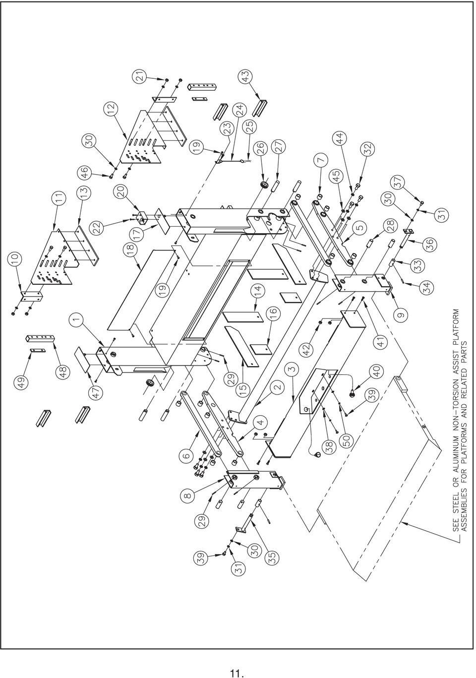
10 TT15 - UNDERCARRIAGE FOR PLATFORMS WITH NO TORSION ASSIST Item Part Number Description Platform Width Frame Weld-For All Other Platforms Frame Weld-For All Other Platforms Frame Weld-For All Other Platforms Frame Weld-2PC. 26" Deep Steel Platform Only Frame Weld-2PC. 26" Deep Steel Platform Only Frame Weld-2PC. 26" Deep Steel Platform Only Brace Weld Brace Weld Brace Weld Bumper Weld Bumper Weld Bumper Weld Lift Arm Asm.-LH, Incl. Item Lift Arm Asm.-RH, Incl. Item Idler Arm Asm., Incl. Item Bushing - Lift Arms and Idler Arms Pivot Support Weld LH Pivot Support Weld RH Mounting Angle Post Support - LH Post Support - RH Backer Plate Frame Brace - Vertical Frame Brace - Horizontal Bumper Brace Post Cover RH Power Unit Cover Screw.25 x Toggle Switch Asm Locknut Screw #10 x Cable Retainer Latch Cable Hairpin Grommet Pin - Arms to Frame Weld Pin - Arms to Pivot Support Weld Spring Pin.25 x Flatwasher Lockwasher Screw.50 x Pivot Tube Spring Pin Pin Weld LH - Pivot Support Weld to Platform Pin Weld RH - Pivot Support Weld to Platform Screw.38 x Plastic Square Nut Screw License Plate Light Screw -.31 x Locknut Mounting Channel Lockwasher Flatwasher Screw.38 x Post Cover LH Post Support Spacer Tube Spacer Plate Flatwasher - #

11 11.
12 STEEL DECKPLATE PLATFORMS WITH NO TORSION ASSIST Item Part Number Description Platform Width Platform Weld - 1PC. 26" Deep, Incl. Item Platform Weld - 1PC. 26" Deep, Incl. Item Platform Weld - 1PC. 26" Deep, Incl. Item Platform Weld - 2PC. 26" Deep, Incl. Items 2,3,4, Platform Weld - 2PC. 26" Deep, Incl. Items 2,3,4, Platform Weld - 2PC. 26" Deep, Incl. Items 2,3,4, Bushing - Platforms Hinge Pin Flatwasher Retaining Ring Locking Cable Asm Locking Cable Asm Locking Cable Asm Spring Flatwasher Cotter Pin

13 ALUMINUM EXTRUSION PLATFORMS WITH NO TORSION ASSIST Item Part Number Description Platform Width Platform Weld - 1PC. 26" Deep, Incl. Item Platform Weld - 1PC. 26" Deep, Incl. Item Platform Weld - 1PC. 26" Deep, Incl. Item Platform Weld - 1PC. 32" Deep, Incl. Item Platform Weld - 1PC. 32" Deep, Incl. Item Platform Weld - 1PC. 32" Deep, Incl. Item Platform Weld - 2PC. 26" Deep, Incl. Items 2,3,4, Platform Weld - 2PC. 26" Deep, Incl. Items 2,3,4, Platform Weld - 2PC. 26" Deep, Incl. Items 2,3,4, Platform Weld - 2PC. 32" Deep, Incl. Items 2,3,4, Platform Weld - 2PC. 32" Deep, Incl. Items 2,3,4, Platform Weld - 2PC. 32" Deep, Incl. Items 2,3,4, Bushing - Platforms Retaining Ring Hinge Pin Flatwasher Locking Cable Asm Locking Cable Asm Locking Cable Asm Spring Flatwasher Cotter Pin

14 TT15 - STEEL 42.00" DEEP PLATFORMS WITH TORSION ASSIST Item Part Number Description Platform Width Frame Weld Frame Weld Frame Weld Platform Weld - 2PC. 42" Deep, Incl. Items 11,46, Platform Weld - 2PC. 42" Deep, Incl. Items 11,46, Platform Weld - 2PC. 42" Deep, Incl. Items 11,46, Brace Weld Brace Weld Brace Weld Bumper Weld Bumper Weld Bumper Weld Support Cable Support Cable Support Cable Torsion Bar Torsion Bar Torsion Bar Locking Cable Locking Cable Locking Cable Lift Arm Asm. - LH, Incl. Item Lift Arm Asm. - RH, Incl. Item Idler Arm Asm., Incl. Item Bushing - Lift Arms, Idler Arms, and Platform HD Pivot Support Weld LH HD Pivot Support Weld RH Mounting Angle Post Support-LH Post Support-RH Backer Plate Frame Brace - Vertical Frame Brace - Horizontal Bumper Brace Post Cover RH Power Unit Cover Screw.25 x Toggle Switch Asm Locknut Screw - #10 x Cable Retainer Latch Cable Hairpin Grommet Pin - Arms to Frame Weld Pin - Arms to Pivot Support Weld Spring Pin.25 x Flatwasher Lockwasher Screw.50 x Screw.38 x Pin Weld RH Pivot Support Weld to Platform Locknut Adjustment Bracket - LH Pivot Support Weld to Platform Plastic Square Nut Screw

15 TT15 - STEEL 42.00" DEEP PLATFORMS WITH TORSION ASSIST - CONTINUED Item Part Number Description Platform Width License Plate Light Screw -.31 x Locknut Hinge Pin Flatwasher Spring Flatwasher Cotter Pin Mounting Channel Lockwasher Retaining Ring Screw.38 x Post Cover LH Post Support Spacer Tube Spacer Plate 2 15.

16 TT15 - ALUMINUM 44.00" DEEP PLATFORMS WITH TORSION ASSIST Item Part Number Description Platform Width Frame Weld Frame Weld Frame Weld Platform Weld - 2PC. 44" Deep, Incl. Items 54,46, Platform Weld - 2PC. 44" Deep, Incl. Items 54,46, Platform Weld - 2PC. 44" Deep, Incl. Items 54,46, Brace Weld Brace Weld Brace Weld Bumper Weld Bumper Weld Bumper Weld Support Cable Support Cable Support Cable Torsion Bar Torsion Bar Torsion Bar Locking Cable Locking Cable Locking Cable Lift Arm Asm. - LH, Incl. Item Lift Arm Asm. - RH, Incl. Item Idler Arm Asm., Incl. Item Bushing - Lift Arms, Idler Arms HD Pivot Support Weld LH HD Pivot Support Weld RH Mounting Angle Post Support-LH Post Support-RH Backer Plate Frame Brace - Vertical Frame Brace - Horizontal Bumper Brace Post Cover RH Power Unit Cover Screw.25 x Toggle Switch Asm Locknut Screw #10 x Cable Retainer Latch Cable Hairpin Grommet Pin - Arms to Frame Weld Pin - Arms to Pivot Support Weld Spring Pin.25 x Flatwasher Lockwasher Screw.50 x Screw.38 x Pin Weld RH Pivot Support Weld to Platform Locknut Adjustment Bracket - LH Pivot Support Weld to Platform Plastic Square Nut Screw

17 TT15 - ALUMINUM 44.00" DEEP PLATFORMS WITH TORSION ASSIST - CONTINUED Item Part Number Description Platform Width License Plate Light Screw -.31 x Locknut Hinge Pin Flatwasher Spring Flatwasher Cotter Pin Mounting Tube Lockwasher Retaining Ring Bushing Screw.38 x Post Cover LH Post Support Spacer Tube Spacer Plate 2 17.

18 BUMPER-LIGHT ASSEMBLY - OPTIONAL Item Part Number Description Platform Width Bumper Light Asm Kit - includes items Bumper Light Asm Kit - includes items Bumper Light Asm Kit - includes items Bumper Weld Bumper Weld Bumper Weld Plastic Square Nut Screw License Plate Light Screw -.31 x Locknut Stop/Turn/Tail Lamp Back-up Lamp Grommet Wire Harness - 3 Wire Wire Harness - 2 Wire Bumper Brace Flatwasher - #

19 TROUBLESHOOTING GUIDE TT15ET Test Equipment: psi pressure gauge 2. DC voltmeter/ohm meter 3. DC amp meter 4. standard mechanics tools Note: Please refer to the electrical diagrams and hose connection drawings in the liftgate s owners manual when troubleshooting. This guide is only for standard Thieman liftgates. Special liftgates with options other than those in the owner s manual will require special diagrams for troubleshooting. Read and understand this entire guide completely before doing any troubleshooting. Certain listed problems may be related to other problems listed so a comprehensive knowledge is required before proceeding. Problem Pump motor will not run in the raise mode Causes a. Tripped circuit breaker b. Blown 20A fuse c. Defective or undercharged battery(ies) d. Improper battery cable connection or improper ground connection e. Defective or improperly wired raise switch f. Defective or improperly wired solenoid start switch g. Defective pump motor Corrections a. Reset the circuit breaker located within 2ft of the liftgate supply battery(ies). b. Replace 20A fuse c. The at rest voltage for the batteries without the engine running and under no load should be at least 12.5V. The minimum voltage between the motor stud and ground is 9V at maximum load conditions. If proper voltage is not present, charge or replace the batteries. The battery(ies) on the vehicle should be that which has a minimum 150 amp reserve capacity. d. Trace battery and ground cable connections to locate improper connection(s). Make sure the ground cable from the batteries to the frame is a heavy 2ga. cable and that is connected to bare metal on the frame. Make sure there is 12.5V present at the large terminal on the motor start solenoid where the 2ga. cable from the batteries is connected. Replace any damaged cables and repair any bad connections. e. Check for voltage on the black wire at the control switch. If no voltage is present the black wire from the motor start solenoid is loose or broken and needs repaired. If voltage is present then check for voltage at the white wire on the switch with the switch in the RAISE position. If no voltage is present, replace the switch. f. Check for voltage on the white wire at the motor start switch when the switch is activated. If no voltage exists the white wire is loose or broken between the switch and the motor start solenoid. Check that the purple ground wire on the start solenoid is connected properly and there are no bad connections. If there is voltage on the white wire and the coil does not 19.

20 energize or if there is no voltage present at the motor terminal then replace the start switch. g. With the switch activated in the RAISE position and the motor start solenoid is activated, check for voltage at the motor terminal. If voltage is present and the motor is not running, replace the motor. 2. Problem Liftgate will not raise to bed with a load and the pump motor running Causes a. Low hydraulic fluid b. Overload condition c. Improperly adjusted or defective main relief valve d. Lift cylinders are bypassing, liftgate is drifting down e. Broken hydraulic line f. Clogged or disconnected suction line g. Defective pump Corrections - a. Make sure the reservoir has the proper amount of fluid. Check for the fluid line through the plastic reservoir. The hydraulic fluid should be within 1/2 of the top of the reservoir with the liftgate in the lowered position. Fill with Dexron III automatic transmission fluid. b. The power unit on the TT15 is equipped with a lifting relief valve to prevent overloading of the liftgate. The relief setting for the TT15 is 2200 psi. c. See section c above for relief valve setting. Plumb a pressure gauge into the high pressure circuit of the liftgate. Remove all loads from the liftgate s platform. Engage the RAISE switch until the liftgate is fully raised. Keep the RAISE switch engaged until the pump bypasses through the relief valve and note the pressure on the gauge at this time. If the rated relief pressure is not present during relief, adjust the high pressure relief valve setting as necessary. If the relief pressure is not attainable the relief valve must be cleaned and/or replaced or the pump is defective. See part g below. d. If the liftgate will not raise with a load on the platform but empty is raising slowly or only partially, the cylinders may be bypassing. To check for bypassing cylinders do the following. Lower the gate to the ground to relieve all pressure from the cylinders. Disconnect the cylinders from the liftarm. Press the RAISE switch until the cylinders is fully retracted. Disconnect the return line from the power unit and put the end of the line in a container to catch any oil which comes out during this test. Press the RAISE switch for 15 to 20 seconds and watch for a steady stream of fluid coming out of the return line into the container. If no steady stream of oil is present connect the hose to the butt end of the cylinders after removing the return line and fitting. Re-attach the return line and fitting to the rod end port. Put the loose end of the return line in a container to catch any oil, which comes out during this test. Press the RAISE switch until the cylinders is fully extended. Press the RAISE switch for 15 to 20 seconds and watch for a steady stream of fluid coming out of one of the disconnected hose ends into the container. Replace or rebuild any cylinders with fluid coming out of the return line, as this indicates fluid is 20.

21 bypassing the piston seals on the cylinder. Reconnect rebuilt or replaced cylinders and hoses as before. e. Broken or punctured hydraulic lines and fittings must be replaced with care to avoid injury from high pressure oil streams. f. With the liftgate at the ground, disconnect the power unit and remove the reservoir. Check to see if the suction tube is clogged or has fallen out of the pump base. Clean the screen or reattach the suction tube as required. g. If all else fails replace the power unit, it is probably worn out. 3. Problem Liftgate will not lower Causes - a. Defective lowering solenoid coil or valve b. Clogged or defective hydraulic lines, fittings or flow controls Corrections - a. With the LOWER switch engaged check for voltage on the green wire at the switch. If no voltage is present replace the switch. If voltage is present, with the LOWER switch engaged, check for voltage at the green wire on the lower solenoid valve coil terminal. If no voltage is present, the green wire from the LOWER switch is loose or broken and needs replaced. If there is voltage (minimum of 9.5 volts) and the valve is not opening to allow the gate to lower, either the lower coil is bad or the entire lower coil/valve assembly is bad. To check to see if the coil is defective, remove the green wire from the spade terminal on the lower coil and check for continuity between the spade terminal and the nut, which holds the coil on the valve stem. If continuity does not exist, replace the defective coil, otherwise replace the defective lower coil/valve assembly. b. Remove any obstruction in the hoses, fittings or flow controls or replace any hose, fitting or flow control, which does not allow fluid to flow through freely. 4. Problem Liftgate raises slowly The raise speed of the TT15 on a 45 bed height while empty at 70 F is approximately 8-9 seconds. The raise speed loaded for the same conditions is approximately seconds. Causes - a. Overload condition b. Cold weather c. Partially blocked suction screen d. Lift cylinders are bypassing e. Improperly adjusted or defective raise relief valve f. Low voltage and/or bad ground g. Worn out pump Corrections a. See section 2b b. Refer to Owner s Manual for alternative oils to use for cold weather conditions. c. Remove reservoir and clean or replace suction screen as necessary. d. See section 2d e. See section 2c f. The minimum voltage between the motor stud and ground is 9.5 volts at maximum load conditions. See section 1b and 1c. 21.
22 g. After all other corrections are performed it will be necessary to replace the pump. 5. Problem Foamy oil flowing from reservoir breather Causes - a. Air is present in the system Corrections - a. This can occur if air enters the system if the fluid level is low, see problem 2, part a, or if the suction tube is disconnected, see problem 2, part f. Also air may enter through fittings, which are not tightened properly, so check for any leaks around fittings or hoses. Once the source of the air is determined, the cylinders must be bled of all air. Most air can be removed from the system by lowering the gate to the ground to relieve all pressure from the cylinders, unpinning the cylinders and cycling them back and forth several times from fully extended to fully retracted and allowing the pump to bypass through the relief valves for a few seconds in each direction. If you have any questions or problems that are not covered in this guide please call Thieman s Engineering Department at
23 23.
24 Rev. 7/12 7.5C MP76400
Railgates By THIEMAN IMPORTANT! KEEP IN VEHICLE! PLEASE READ AND UNDERSTAND THE CONTENTS OF THIS MANUAL BEFORE OPERATING THE EQUIPMENT.
 TVL SERIES Railgates By THIEMAN TVL 20, TVL 30, TVL 20A, TVL 30A OWNERS MANUAL/PARTS LIST! IMPORTANT! KEEP IN VEHICLE! PLEASE READ AND UNDERSTAND THE CONTENTS OF THIS MANUAL BEFORE OPERATING THE EQUIPMENT.
Railgates By THIEMAN TVL 20, TVL 30, TVL 20A, TVL 30A OWNERS MANUAL/PARTS LIST IMPORTANT! KEEP IN VEHICLE!
 TVL SERIES Railgates By THIEMAN TVL 20, TVL 30, TVL 20A, TVL 30A OWNERS MANUAL/PARTS LIST! NATIONAL TRUCK EQUIPMENT ASSOCIATION Member IMPORTANT! KEEP IN VEHICLE! PLEASE READ AND UNDERSTAND THE CONTENTS
DANGER DANGER. General Information. Safety Is Your Responsibility. Ordering Parts. Contact Information
 Safety Safety Is Your Responsibility DANGER To avoid personal injury or death, carefully read and understand all instructions pertaining to the Anthony Liftgates product. Do not attempt to install, operate,
INTERLIFT ILR OWNERS MANUAL. INTERLIFT, INC. a member of MBB. 15939 Piuma Ave., Cerritos, CA 90703 Tel (888)-774-5844 Fax (562) 924-8318
-774-5844 Fax (562) 924-8318") INTERLIFT ILR OWNERS MANUAL INTERLIFT, INC. a member of MBB 15939 Piuma Ave., Cerritos, CA 90703 Tel (888)-774-5844 Fax (562) 924-8318 1 TABLE OF CONTENT PAGE TECHNICAL DESCRIPTION 3 GENERAL INFORMATION
INTERLIFT ILR OWNERS MANUAL INTERLIFT, INC. a member of MBB 15939 Piuma Ave., Cerritos, CA 90703 Tel (888)-774-5844 Fax (562) 924-8318 1 TABLE OF CONTENT PAGE TECHNICAL DESCRIPTION 3 GENERAL INFORMATION
Chapter 7 Hydraulic System Troubleshooting
 Chapter 7 Hydraulic System Troubleshooting General The following troubleshooting information is provided as a general guide to identify, locate and correct problems that may be experienced with the hydraulic
PUMP MAINTENANCE SCHEDULE AND CHECKLISTS
 PUMP MAINTENANCE SCHEDULE AND CHECKLISTS Providing a maintenance schedule defined specifically by run hours or yardage pumped serves only as a general guideline given the large amount of variables a unit
HYDRAULIC LIFT TABLE CART 2200-LB.
 HYDRAULIC LIFT TABLE CART 2200-LB. OWNER S MANUAL WARNING: Read carefully and understand all MACHINE ADJUSTMENT AND OPERATION INSTRUCTIONS before operating. Failure to follow the safety rules and other
Hydraulic Transmission Jacks Operating Instructions & Parts Manual
 Blackhawk Automotive is a Licensed Trade Mark Made by SFA Companies, Kansas City, MO Hydraulic Transmission Jacks Operating Instructions & Parts Manual Model BH7011 BH7210 Capacity 1/2 Ton 1 Ton SFA Companies
Oil and Coolant Circulating Heating System. Model - OCSM
 Oil and Coolant Circulating Heating System Model - OCSM Installation & Operation Manual 216280-000 REV 2 Identifying Your System The HOTSTART heating system is designed to heat fluids for use in marine
FJ2. 2 Ton Trolley Floor Jack Assembly & Operating Instructions
 FJ2 2 Ton Trolley Floor Jack Assembly & Operating Instructions READ ALL INSTRUCTIONS AND WARNINGS BEFORE USING THIS PRODUCT. This manual provides important information on proper operation & maintenance.
M-06-09 REV. B APRIL 2008 OPERATION MANUAL GPT-25, GPT-3, GPT-4 & GPT-5
 M-06-09 REV. B APRIL 2008 OPERATION MANUAL GPT-25, GPT-3, GPT-4 & GPT-5 MAXON Lift Corp. 2008 TABLE OF CONTENTS WARNINGS... 4 LIFTGATE TERMINOLOGY... 5 RECOMMENDED DAILY OPERATION CHECKS... 6 DECALS...
INSTRUCTIONS AND PARTS LIST FOR MODEL 70H & 75H HAND-OPERATED HYDRAULIC PRESS
 INSTRUCTIONS AND PARTS LIST FOR MODEL 70H & 75H HAND-OPERATED HYDRAULIC PRESS SETTING UP THE PRESS FOR OPERATION For shipping convenience, the gauge, pump handle, hoist crank, screw nose and base angles
Hydraulic Trouble Shooting
 Hydraulic Trouble Shooting Hydraulic systems can be very simple, such as a hand pump pumping up a small hydraulic jack, or very complex, with several pumps, complex valving, accumulators, and many cylinders
CDS TROUBLESHOOTING SECTION I. VACUUM. 1.0. Weak vacuum at wand. Gauge reads normal (10hg to 14hg)
") CDS TROUBLESHOOTING SECTION I. VACUUM 1.0. Weak vacuum at wand. Gauge reads normal (10hg to 14hg) 1.1. Clogged hoses or wand tube. Disconnect hoses and carefully check for an obstruction. 1.2. Excessive
CDS TROUBLESHOOTING SECTION I. VACUUM 1.0. Weak vacuum at wand. Gauge reads normal (10hg to 14hg) 1.1. Clogged hoses or wand tube. Disconnect hoses and carefully check for an obstruction. 1.2. Excessive
HYDRAULIC TABLE CART 500-LB.
 HYDRAULIC TABLE CART 500-LB. OWNER S MANUAL WARNING: Read carefully and understand all MACHINE ADJUSTMENT AND OPERATION INSTRUCTIONS before operating. Failure to follow the safety rules and other basic
10 TON HYDRAULIC PRESS
 10 TON HYDRAULIC PRESS Model Nos. CSA10F and CSA10B OPERATING & MAINTENANCE INSTRUCTIONS 0200 SPARE PARTS and SERVICING Please contact your nearest dealer, or CLARKE International, on one of the following
-1- SPECIFICATIONS 002085 CONE SETTER PLATFORM ATTACHMENT INDEX
 -1-002085 CONE SETTER PLATFORM ATTACHMENT INDEX I. GENERAL EQUIPMENT : A. Intent Statement B. Cone Setter Platform II. III. 1. Understructure Frame 2. Mounting Components 3. Paint 4. Basket 5. Labels 6.
VOYAGER 570G. 744A Sprayer Control
 VOYAGER 570G 744A Sprayer Control U S E R M A N U A L U S E R M A N U A L Table of Contents CHAPTER 1 - INTRODUCTION...1 SYSTEM CONFIGURATIONS...1 KIT CONTENTS...3 CONTROL HOUSING ASSEMBLY...5 CHAPTER
Power Cube Open Source Ecology Page 1. Power Cube. Version 4
 Power Cube Open Source Ecology Page 1 Power Cube Version 4 Power Cube Open Source Ecology Page 2 Contents Table of Contents Power Cube... 1 Contents...2 Introduction... 3 Bill Of Materials...4 Discrete
SECTION G2: CABLE PROCESSOR MODULE MAINTENANCE
 SECTION G2: CABLE PROCESSOR MODULE MAINTENANCE Cable Processor Module overview WARNING! When tipping the Cable Processor Module back, (after removing the toggle arm pin), use extreme caution not to drop
Auto-belay Cable Replacement Process
 Auto-belay Cable Replacement Process Version 2.00 WARNING: The air pressure in the auto-belay system is what causes the cable to be retracted when releasing the cable or climbing the wall with the cable
Table of Contents. Overview 1. Pump Disassembly 2. Control Disassembly / Reassembly 7. Pump Reassembly 13. Adjustment Procedures DR Control 19
 Table of Contents Overview 1 Pump Disassembly 2 Control Disassembly / Reassembly 7 Pump Reassembly 13 Adjustment Procedures DR Control 19 Adjustment Procedures DRG Control 20 Adjustment Procedures DFR
Pallet Jack. OWNER S MANUAL Model MH1230. Important Safety Instructions Assembly Instructions Parts and Hardware Identification
 OWNER S MANUAL Model MH1230 Important Safety Instructions Assembly Instructions Parts and Hardware Identification Pallet Jack CAUTION: Read, understand and follow ALL instructions before using this product
WHAT YOU DON T KNOW ABOUT ACCUMULATORS CAN KILL YOU!
 WHAT YOU DON T KNOW ABOUT ACCUMULATORS CAN KILL YOU! Atlanta (Monroe) GA 770-267-3787 gpm@gpmhydraulic.com www.gpmhydraulic.com What You Don t Know About Hydraulic Accumulators Can Kill You TABLE OF CONTENTS
MODEL G300 BRAKE BLEEDER
 MODEL G300 BRAKE BLEEDER Installation, Operation & Repair Parts Information Branick Industries, Inc. 4245 Main Avenue P.O. Box 1937 Fargo, North Dakota 58103 REV060616 P/N: 81-0035G 1 THIS PAGE INTENTIONALLY
SELF-STEERING AXLE TABLE OF CONTENTS
 SELF-STEERING AXLE TABLE OF CONTENTS Section 1 - Introduction Section 2 - Pre-Installation Check List Section 3 - Ride Height Adjustments Section 4 - Suspension Mount Section 5 - Axle Mount Section 6 -
HYDRAULIC TABLE CART
 Owner s Manual & Safety Instructions Save This Manual Keep this manual for the safety warnings and precautions, assembly, operating, inspection, maintenance and cleaning procedures. Write the product s
Tech. Services: (800) 477-8326 Fax: (800) 765-8326 Order Entry: (800) 541-1418 Fax: (800) 288-7031 Internet Address: http://www.powerteam.
 477-8326 Fax: (800) 765-8326 Order Entry: (800) 541-1418 Fax: (800) 288-7031 Internet Address: http://www.powerteam.") ORIGINAL INSTRUCTIONS Form No.102842 5 SPX Hydraulic Technologies 5885 11th Street Rockford, IL 61109-3699 USA Tech. Services: (800) 477-8326 Fax: (800) 765-8326 Order Entry: (800) 541-1418 Fax: (800)
ORIGINAL INSTRUCTIONS Form No.102842 5 SPX Hydraulic Technologies 5885 11th Street Rockford, IL 61109-3699 USA Tech. Services: (800) 477-8326 Fax: (800) 765-8326 Order Entry: (800) 541-1418 Fax: (800)
ILLUSTRATED PARTS LIST
 TW400 WITH 390cc HONDA ENGINE 390cc 2 WHEEL DRIVE UTILITY VEHICLE ILLUSTRATED S LIST 390cc 2WD B O D Y D I A G R A M 390cc 2WD F R A M E D I A G R A M 390cc 2WD D R I V E T R A I N D I A G R A M DESCRIPTION
EVANS ELECTRONIC TEMPERATURE CONTROL TROUBLESHOOTING GUIDE for systems equipped with electric coolant valve and external PC board.
 EVANS ELECTRONIC TEMPERATURE CONTROL TROUBLESHOOTING GUIDE for systems equipped with electric coolant valve and external PC board. This Troubleshooting Guide covers the electric coolant valve and control
Table of Contents WARNING SYMBOLS AND DEFINITIONS
 Table of Contents SAFETY INSTALLATION OPERATION MAINTENANCE Safety... 2 Specifications... 4 Installation... 5 Operation... 8 WARNING SYMBOLS AND DEFINITIONS Maintenance... 9 Parts List and Assembly Diagram...
Hydraulic Troubleshooting PRESENTED BY
 Hydraulic Troubleshooting PRESENTED BY NORMAN KRONOWITZ Introduction Welcome to the CMA/Flodyne/Hydradyne s Hydraulic Troubleshooting presentation. We will introduce many aspects of troubleshooting hydraulic
46431x92A Garden Tractor (1998) Page 1 of 16 Body Chassis
 Page 1 of 16 Body Chassis") 46431x92A Garden Tractor (1998) Page 1 of 16 Body Chassis 46431x92A Garden Tractor (1998) Page 2 of 16 Body Chassis 1 092546E701 Bracket, Seat 2 091963 Z Plate Assembly, Switch 3 164X26 Spring, Compression
46431x92A Garden Tractor (1998) Page 1 of 16 Body Chassis 46431x92A Garden Tractor (1998) Page 2 of 16 Body Chassis 1 092546E701 Bracket, Seat 2 091963 Z Plate Assembly, Switch 3 164X26 Spring, Compression
PALLET JACK - 2.5 TON
 PALLET JACK - 2.5 TON 39939 SET UP AND OPERATING INSTRUCTIONS Visit our website at: http://www.harborfreight.com Read this material before using this product. Failure to do so can result in serious injury.
INSTALLATION INSTRUCTIONS. 6111 Air Spring Kit 2011+ Ford F250/F-350 Single Wheel 2WD 2011+ Ford F350 Dually 2WD IMPORTANT NOTES
 INSTALLATION INSTRUCTIONS 6111 Air Spring Kit 2011+ Ford F250/F-350 Single Wheel 2WD 2011+ Ford F350 Dually 2WD Thank you for purchasing a quality Hellwig Product. PLEASE READ THIS INSTRUCTION SHEET COMPLETELY
Rating when used as a weight carrying hitch without spring bars:
 BOLT-TOGETHER WEIGHT DISTRIBUTING HITCH SYSTEM Rating when used as a weight distributing hitch with spring bars: Part Number 48051 4805 48053 48054 Max Tongue Weight 550 Ibs. 750 Ibs. 1000 Ibs. 1400 lbs.
ATS Overhead Table Shelf System INSTRUCTION MANUAL
 ATS Overhead Table Shelf System INSTRUCTION MANUAL ATS Overhead Table Shelf System Instruction Manual Warranty Newport Corporation warrants this product to be free of defects in material and workmanship
TITAN 13 x 2 ½ BRAKES
 INSTALLATION INSTRUCTION AND SERVICE MANUAL Actuator/Trailer Dealer - Please provide these instructions to the consumer. Consumer - Read and follow these instructions. Keep them with the trailer for future
INSTALLATION INSTRUCTIONS. 6108 Air Spring Kit 2011+ Ford F250 Single Wheel 4WD 2011+ Ford F350 Dually 4WD (2011 F350 Single Wheel 4WD use p/n 6113)
") INSTALLATION INSTRUCTIONS 6108 Air Spring Kit 2011+ Ford F250 Single Wheel 4WD 2011+ Ford F350 Dually 4WD (2011 F350 Single Wheel 4WD use p/n 6113) Thank you for purchasing a quality Hellwig Product. PLEASE
INSTALLATION INSTRUCTIONS 6108 Air Spring Kit 2011+ Ford F250 Single Wheel 4WD 2011+ Ford F350 Dually 4WD (2011 F350 Single Wheel 4WD use p/n 6113) Thank you for purchasing a quality Hellwig Product. PLEASE
SERVICE GUIDE For WARN PULLZALL 120v AC &100v AC P/N 685000 & 685001
 SERVICE GUIDE For WARN PULLZALL 120v AC &100v AC P/N 685000 & 685001 REPAIR / REPLACEMENT INSTRUCTIONS TROUBLE SHOOTING GUIDE 986765A2.doc Page 1 of 50 WARNING This guide identifies potential hazards and
Service Manual Rol-Lift
 R 2000 Service Manual Rol-Lift Series: T and E Developed by Generic Parts Service This manual is intended for basic service and maintenance of the Rol-Lift pallet jack. The pallet jacks you are servicing
123 Industrial Loop Road Paynesville, MN 56362 Phone: 1-800-864-1649 www.master-mfg.com
 123 Industrial Loop Road Paynesville, MN 56362 Phone: 1-800-864-1649 www.master-mfg.com INTRODUCTION The purpose of this manual is to assist you in the assembly, operation and maintenance of your sprayer
DIAMOND Retractable Rodding Robot Model SPRAYROD-R
 2004-12-21 2 1 (23) DIAMOND Retractable Rodding Robot Model SPRAYROD-R 2004-12-21 2 2 (23) Table of contents 1 TECHNICAL DESCRIPTION...4 1.1 MAIN DETAILS...5 1.2 COMPONENTS DESCRIPTION...5 1.2.1 Pneumatic
SunMaxx Solar Filling Station Operating Instructions
 SunMaxx Solar Filling Operating Instructions Content 1. Declaration of conformity... 2 2. Introduction... 2 3. Transportation and unpacking... 4 4. Mounting and commissioning... 5 5. End of operation...
Technical Guide 08/15/14
 Technical Guide 08/15/14 1 Table of Contents Contact information.3 Identifying your system..4-8 Model Number Serial number location Parts of your fuel system..9-14 Fuel pump diagram Wire harness schematics
SE-100-1, SE-200-1, SE-500-1, and SE-1000-1 AIR CHAMP PRODUCTS. User Manual SE BRAKE MODELS: (i) MTY (81) 83 54 10 18 ventas@industrialmagza.
 MTY (81) 83 54 10 18 ventas@industrialmagza.") AIR CHAMP PRODUCTS User Manual SE BRAKE MODELS: SE-00-, SE-200-, SE-500-, and SE-000- (i) FORM NO. L-20084-E-040 In accordance with Nexen s established policy of constant product improvement, the specifications
AIR CHAMP PRODUCTS User Manual SE BRAKE MODELS: SE-00-, SE-200-, SE-500-, and SE-000- (i) FORM NO. L-20084-E-040 In accordance with Nexen s established policy of constant product improvement, the specifications
READ AND UNDERSTAND ALL INSTRUCTIONS AND WARNINGS PRIOR TO INSTALLATION OF SYSTEM AND OPERATION OF VEHICLE.
 491 W. Garfield Ave., Coldwater, MI 49036 Phone: 517-279-2135 Web/live chat: www.bds-suspension.com E-mail: tech-bds@sporttruckusainc.com Product: GM Leaf Spring READ AND UNDERSTAND ALL INSTRUCTIONS AND
Instructions and precautions. Fork Height. Visit our website at: http://www.harborfreight.com
 Pallet Jack Item 68760 / 68761 Instructions and precautions Specifications Capacity Control Lever Fork Height Fork Length Fork Width Maximum Minimum Width over Forks Steering Wheel Dia. 2-1/2 Ton (5,000
OWNER'S MANUAL P O L Y C A R T, 1 7 C U B I C F O O T M O D E L : P C T - 1 7 B H. Assembly Installation Operation Repair Parts
 OWNER'S MANUAL P O L Y C A R T, 7 C U B I C F O O T M O D E L : P C T - 7 B H Assembly Installation Operation Repair Parts For use with Lawn/Garden Tractors For the latest product updates and setup tips:
Cooling system components, removing and installing
 Page 1 of 34 19-1 Cooling system components, removing and installing WARNING! The cooling system is pressurized when the engine is warm. When opening the expansion tank, wear gloves and other appropriate
1 TON FOLDING CRANE CFC1000
 1 TON FOLDING CRANE CFC1000 OPERATION &MAINTENANCE INSTRUCTIONS 0401 SPECIFICATIONS MAXIMUM SAFE WORKING LOADS (kg) 1 2 3 4 1000 750 500 250 MAXIMUM LIFT HEIGHT - 1920mm HYDRAULIC RAM OIL CAPACITY - 450CC
HC-3000 SERIES RAKE Parts Breakdown DURABILT INDUSTRIES, LLC - 1810 AIRPORT ROAD POCAHONTAS ARKANSAS 72455
 HC-3000 SERIES RAKE Parts Breakdown 1 SPRING TOWER PARTS PAGE 4 RAKE WHEEL AND ARM PARTS PAGE 8 PIVOT PARTS PAGE 6 6 2,3,4 23 21 7 22 24 HUB & SPINDLE PARTS 8 THRU 20 HYDRAULIC PARTS PAGES 10 AND 12 1
Rexroth Hydraulic Pump A10VO Series User Manual
 Rexroth Hydraulic Pump A10VO Series User Manual Rexroth Hydraulic pump A10VO Series User Manual Revised 5/1/2009 Page 1 of 12 Functional Purpose This pump is preferred over a fixed displacement (gear)
Fleck 4650. Service Manual INSTALLATION AND START-UP PROCEDURE TABLE OF CONTENTS JOB SPECIFICATION SHEET
 Fleck 4650 Service Manual TABLE OF CONTENTS JOB SPECIFICATION SHEET...1 INSTALLATION AND START-UP PROCEDURE...1 CONTROL VALVE DRIVE ASSEMBLY...2 CONTROL DRIVE ASSEMBLY FOR CLOCK...3 BYPASS VALVE ASSEMBLY...4
LIFT N RACK PRO OPERATING & INSTALLATION GUIDE 5500 Lb. LIFT CAPACITY
 LIFT N RACK PRO OPERATING & INSTALLATION GUIDE 5500 Lb. LIFT CAPACITY IMPORTANT: READ THIS MANUAL BEFORE IN-STALLING, OPERATING OR MAINTAINING YOUR LIFT. Chassis Liner Company Sales Office Toll Free: 800-242-2448
1000-LB. TRAILER JACK OWNER S MANUAL
 1000-LB. TRAILER JACK OWNER S MANUAL WARNING: Read carefully and understand all INSTRUCTIONS before operating. Failure to follow the safety rules and other basic safety precautions may result in serious
12-Volt Negative Ground Installation Instructions
 12-Volt Negative Ground Installation Instructions For Part Number: 1141, 1164, 1165, 1181 CAUTION!!! Before installing, please read the following important information... 1. The Ignitor is designed for
15GAL STEEL OIL DRAIN WITH 110V PUMP
 15GAL STEEL OIL DRAIN WITH 110V PUMP OWNER S MANUAL WARNING: Read carefully and understand all ASSEMBLY AND OPERATION INSTRUCTIONS before operating. Failure to follow the safety rules and other basic safety
Installation, operation and maintenance manual
 Installation, operation and maintenance manual TWO POST LIFT HCT2.1AL30 HCT2.1AL40 HCT2.5AL30 HCT2.5AL40 READ THIS ENTIRE MANUAL BEFORE INSTALLATION TO ENSURE A CORRECT OPERATION AND LONG SERVICE LIFE
7600 SAND STREET, FORT WORTH, TX 76118. www.kodiaktrailer.com -2-
 7600 SAND STREET, FORT WORTH, TX 76118 www.kodiaktrailer.com -2- CONTENTS SECTION I. INTRODUCTION II. GENERAL INFORMATION III. SAFETY INFORMATION IV. INSTALLATION INFORMATION V. SOLENOID REVERSING VALVES
SHOP PRESS ASSEMBLY INSTRUCTIONS
 SHOP PRESS ASSEMBLY INSTRUCTIONS 5250-50 Ton Manual Shop Press With Winch PRESS SPECIFICATIONS Sunex Part No. A B C D E F G H I 5250 74" 35" 29.75" 13" 6.75" 1.25" Y Y Y(2) A - Total Height B - Inside
ROUGHNECK II Pumpless Drain
 SERVICE BULLETIN SB4027 Rev. I 1/11 For Used Oil Only ROUGHNECK II Pumpless Drain Model #4110-022 FOR USED OIL ONLY (Black) For Antifreeze Only Model #4110-023 FOR USED ANTIFREEZE ONLY (Green) Patent #
Trouble Shooting. Pump
 Trouble Shooting Pump Trouble Possible Cause Remedy Oil leaking in the area of water pump crankshaft Worn crankshaft seal, bad bearing, grooved shaft, or failure of retainer o-ring. Excessive play on crankshaft
DR ALL-TERRAIN FIELD and BRUSH MOWER
 DR ALL-TERRAIN FIELD and BRUSH MOWER Parts List and Assembly Diagrams Important: Please read the Safety and Operating Instructions and the separate Engine Manufacturer s Owners Manual to become familiar
UHIR Series. Horizontal or Vertical Mounting Industrial / Commercial Electric Unit Heater. Owner s Manual
 UHIR Series Horizontal or Vertical Mounting Industrial / Commercial Electric Unit Heater Owner s Manual This manual covers installation, maintenance and repair parts. Read carefully before attempting to
123 Industrial Loop Road Paynesville, MN 56362 Phone: 1-800-864-1649 www.master-mfg.com MASTER MANUFACTURING MASTER GARDNER
 123 Industrial Loop Road Paynesville, MN 56362 Phone: 1-800-864-1649 www.master-mfg.com MASTER MANUFACTURING MASTER GARDNER Part Number PCD E3 009B MM Rev 1 Nov. 2010 INTRODUCTION The purpose of this manual
PART 2 FORKLIFT HYDRAULIC SYSTEM
 PART 2 FORKLIFT HYDRAULIC SYSTEM Chapter 1 Description and Operation Component Locations & Circuit Layouts 1 Hydraulic Pump 11 Control Valve 14 Valve Section Oil Flows 15 Anti-Cavitation Valve 22 Velocity
Multi-Pitch Pitching Machine USER MANUAL
 Multi-Pitch Pitching Machine USER MANUAL TABLE OF CONTENTS Thank you for purchasing the Cimarron Multi-Pitch Pitching Machine. The Cimarron Multi-Pitch Pitching Machine is a high performance pitching machine
A.Y. McDonald Mfg. Co. Troubleshooting Submersible and Jet Pumps
 A.Y. McDonald Mfg. Co. Troubleshooting Submersible and Jet Pumps Troubleshooting Submersible Pumps Fuse overload or circuit breaker trips when motor is started 1. Incorrect line voltage. Check the line
13. REAR WHEEL/BRAKE/SUSPENSION
 13. REAR WHEEL/BRAKE/SUSPENSION 13 3.5~4.5kg-m 8.0~10.0kg-m 0.8~1.2kg-m 3.0~4.0kg-m 2.4~3.0kg-m 3.5~4.5kg-m 6.0~8.0kg-m 13-0 13. REAR WHEEL/BRAKE/SUSPENSION 13 REAR WHEEL/BRAKE/SUSPENSION SERVICE INFORMATION...
OWNER S MANUAL Table Tennis Table Patent Pending
 OWNER S MANUAL Table Tennis Table Patent Pending Be sure to write your model number and serial number here for future reference. You can find these numbers printed on the bottom of the table. MODEL # T8179
7.1. Part Lists. Hardware Insertion Machine. Instructions. Instructions
 Instructions Instructions The Parts in this section of the manual are listed by Item Number, Part Number, Description and Quantity. The Item Numbers are in a circle with an arrow pointing to the specific
WE-350 Series ¼ Turn Electric Actuator
 WE-350 Series ¼ Turn Electric Actuator Operation and Installation Manual Pg 1 (Rev. 020113) Table of Contents 1.0 General 1.1 Pre-Installation Inspection 1.2 Storage 1.3 Features & General Information
TABLE OF CONTENTS. I. TROUBLESHOOTING... 2 - Section 1.01: Common Problems/Solutions... 2
 BAL Accu-Slide System I. Table of Contents TABLE OF CONTENTS I. TROUBLESHOOTING... 2 - Section 1.01: Common Problems/Solutions... 2 II. GETTING STARTED... 5 - Section 2.01: Tools You Will Need... 5 - Section
Compressor Service & Maintenance Manual
 Compressor Service & Maintenance Manual C Series COMPRESSOR (D)C1103 (D)C1203 (D)C2106 (D)C2206 (D)C3210 Copyright 2006 DCI. All Rights Reserved. 92311, Rev. C, 08/13 1 C1000 Series Service & Maintenance
Failure to comply with the following cautions and warnings could cause equipment damage and personal injury.
 1.0 IMPORTANT RECEIVING INSTRUCTIONS Visually inspect all components for shipping damage. Shipping Damage is not covered by warranty. If shipping damage is found, notify carrier at once. The carrier is
JANUS INTERNATIONAL CORPORATION INSTALLATION INSTRUCTIONS Pantheon Mini Operator
 JANUS INTERNATIONAL CORPORATION INSTALLATION INSTRUCTIONS Pantheon Mini Operator The Janus Pantheon mini operator does not typically require the provision of any additional site requirements other than
OPERATION AND MAINTENANCE MANUAL WASP, Inc. Bag Cart Model No. A01154D Drawing No. A02022D
 OPERATION AND MAINTENANCE MANUAL WASP, Inc. Bag Cart Model No. A01154D Drawing No. A02022D WASP RECORD OF REVISIONS REV. ISSUE DATE BY REV. ISSUE DATE BY NO. DATE INSERTED NO. DATE INSERTED Original 001
TECHNICAL BULLETIN. Meritor WABCO Cab Leveling Valves and Chassis Leveling Valves. How the Cab Leveling and Chassis Leveling Valves Work
 Revised 02-00 TECHNICAL BULLETIN Meritor WABCO Cab Leveling Valves and Chassis Leveling Valves This technical bulletin covers both cab and chassis leveling valves manufactured by Meritor WABCO. While the
OP300S / OP350 2:1 RATIO TRANSFER PUMP
 OP300S / OP350 2:1 RATIO TRANSFER PUMP OPERATING MANUAL WITH PARTS IDENTIFICATION Copyright 2013 International Pump Manufacturing, Inc. This manual contains IMPORTANT WARNINGS and INSTRUCTIONS. Read and
OPERATING MANUAL CONTRACTOR STYLE AXIAL FANS
 Manual No. BLWR043 Rev. 4 September 2012 OPERATING MANUAL CONTRACTOR STYLE AXIAL FANS CVF-8AC CVF-8AC50 CVF-6ACAN CVF-15ACAN CVF-25ACAN CVF-8A15KIT CVF-8A25KIT MODELS: CVF-8DC CVF-6DCAN CVF-15DCAN CVF-25DCAN
Range Road RR Series Semi-Automatic Firewood Processor. Crated Unit Assembly Manual
 Range Road RR Series Semi-Automatic Firewood Processor Crated Unit Assembly Manual 1 1) Undo 8-18mm x 19mm Nuts and bolts, 2 on each leg of top frame 2) Lift top of Metal crate off and move out of work
Rotary Lift Trouble Shooting Guide
 Rotary Lift Trouble Shooting Guide INDEX I. Surface Lifts Page No. 1. Power Unit... 2 2. Two Post Lifts... 3 3. Four Post Lifts... 4 II. Inground Lifts 1. Semi and Full Hydraulic lifts... 5 2. Side by
OPERATING INSTRUCTION MANUAL FOR S-240 HYDRAULIC CUTTERS WITH PARTS LIST
 HUSKIE TOOLS, INC. OPERATING INSTRUCTION MANUAL FOR S-240 HYDRAULIC CUTTERS WITH PARTS LIST GENERAL INFORMATION GUIDE FOR S-240 CUTTER The following steps are guidelines for safe operation of the Huskie
Class 5 to 7 Truck and Bus Hydraulic Brake System
 Class 5 to 7 Truck and Bus Hydraulic Brake System Diagnostic Guide 1st Edition * 5+0 Important Service tes The information in this publication was current at the time of printing. The information presented
Operating Instruction Manual For S-40B Hydraulic Cutters With Parts List
 HUSKIE TOOLS, INC. Operating Instruction Manual For S-40B Hydraulic Cutters With Parts List GENERAL INFORMATION GUIDE FOR S-40B CUTTER The following steps are guidelines for safe operation of the Huskie
Failure to comply with the following cautions and warnings could cause equipment damage and personal injury.
 1.0 IMPORTANT RECEIVING INSTRUCTIONS Visually inspect all components for shipping damage. Shipping Damage is not covered by warranty. If shipping damage is found, notify carrier at once. The carrier is
LEWIS WINDROWER OWNER / OPERATOR MANUAL
 LEWIS WINDROWER OWNER / OPERATOR MANUAL MODEL # WR-1 WINDROWER Manufactured by: LEWIS BROTHERS MANUFACTURING, INC. Post Office Box 146 Baxley, GA 31513 Tel: (912) 367-4651 Fax: (912) 367-3958 2-21-14 1
Mini-ZT. Parts Manual. Models 915054-1540 915064-1534 915070-1534. 00462700 4/06 Printed in USA
 Mini-ZT Parts Manual Models 0-0 0-00 - 0000 /0 Printed in USA THE MANUAL Before you operate your unit, carefully and completely read manuals supplied with the unit. The contents will provide you with an
TABLE OF CONTENTS. Section 1 - Assembling your new pit bike.
 Orion Pit Bike Sales Owners Manual (All information and content is the property of Orion Pit Bike Sales. Any attempt to copy or resell is a direct violation of our copyright. All violators will be prosecuted)
PEDAL CAR - GO CART ASSEMBLY & OPERATING INSTRUCTIONS
 PEDAL CAR - GO CART 42822 ASSEMBLY & OPERATING INSTRUCTIONS 3491 Mission Oaks Blvd., Camarillo, CA 93011 Visit our Web site at: http://www.harborfreight.com Copyright 2000 by Harbor Freight Tools. All
PC1130 Electric Air Compressor
 Senco Products Inc. 8485 Broadwell Road Cincinnati, Ohio 45244 PC1130 Electric Air Compressor Operating Instructions 2006 by Senco Products, Inc. Warnings for the safe use of this tool are included in
300 SERIES 331, 332, 333, 344, 356 AND 367 MODELS
 Section: MOYNO 500 PUMPS Page: 1 of 8 Date: March 1, 1998 SERVICE MANUAL MOYNO 500 PUMPS 300 SERIES 331, 332, 333, 344, 356 AND 367 MODELS Mechanical Seal Models Packing Gland Models MODELS DESIGN FEATURES
PC1131 Electric Air Compressor
 Senco Products Inc. 8485 Broadwell Road Cincinnati, Ohio 45244 PC1131 Electric Air Compressor Operating Instructions 2006 by Senco Products, Inc. Warnings for the safe use of this tool are included in
CPL SYSTEMS / GROENEVELD AUTOMATIC GREASING SYSTEM COMPLETE SYSTEM CHECK PNEUMATIC PUMP
 CPL SYSTEMS / GROENEVELD AUTOMATIC GREASING SYSTEM COMPLETE SYSTEM CHECK PNEUMATIC PUMP Feb 5, 2003 1 CPL SYSTEMS / GROENEVELD AUTOMATIC GREASING COMPLETE SYSTEM CHECK - PNEUMATIC PUMP THE SYSTEM DOES
Model 854/856. Operating and Assembly Manual. Palmor Products Inc. 5225 Serum Plant Road Thorntown, IN 46071
 Model 854/856 Operating and Assembly Manual Palmor Products Inc. 55 Serum Plant Road Thorntown, IN 46071 3/31/2015 SAFETY RULES Remember, any power equipment can cause injury if operated improperly or
DiscPlus DX195 and DX225 Air Disc Brakes
 Revised 11-04 Technical Bulletin Revised 1 Technical 11-04 Bulletin DiscPlus DX195 and DX225 Air Disc Brakes Inspection, Installation and Diagnostics Air Disc Brake Inspection Intervals and Procedures
Owner s Manual Read and keep this manual. Patents World Wide
 Owner s Manual Read and keep this manual. Patents World Wide S & S Industries, Inc., Sarasota, FL, USA www.trail-gator.com Copyright 2008 All Rights Reserved The following manual is provided to assist
INSTALLATION AND OPERATING INSTRUCTIONS For Model GL1 Gate Locks
 Securitron Magnalock Corp. www.securitron.com ASSA ABLOY, the global leader Tel 800.624.5625 techsupport@securitron.com in door opening solutions INSTALLATION AND OPERATING INSTRUCTIONS For Model GL1 Gate