Instruction Manual VB7000. CarbonMax and CarbonPro II Composite Volleyball Systems ( Either in packages or components ordered separately )
|
|
|
- Ella Bryant
- 9 years ago
- Views:
Transcription
1 Instruction Manual VB7000 CarbonMax and CarbonPro II Composite Volleyball Systems ( Either in packages or components ordered separately ) P A R T S L I S T Item Qty Description Item Qty Description A 2* Standards (one with winch) H 4 Rope Ratchet Net Tensioning Ropes (Provided with Net) B 2 Pole Padding I 1 Top Net Rope Attachment Hook C 2 VB23-CV or VB22-CV Floor Plates (If Applicable) J 2 Collar Straps D 2 VB23-SK or VB235 Floor Sockets (If Applicable) K 1 1/8 Allen Wrench E 4 Cable Covers (provided with net) L 2 Carabiner Clips F 1 Net with Storage Bag M 1 3/16 Allen Wrench G 2 Volleyball Antennas Inspect all contents prior to installation. Report any missing parts to dealer immediately. Read all instructions before proceeding! Socket Instructions are provided with socket if applicable. The CarbonMax and CarbonPro II systems have been designed to set and play. After initial set-up all net height guess work is eliminated. The inner pole has machined marks provided for men's (M), women's (W) and junior (J) official heights. The outer pole has an adjustable bottom foot factory pre-set for VB23 floor sockets. Please read and follow the instructions below carefully to make fine tuning adjustments if needed. 1. Install Standards (A) into floor sockets. Use the net height adjustment crank to extend inner pole to either the W (women s), M (men s) or J (junior) line. The machined line should be above but touching the collar. If your sockets are 3 1/2 or 4 request free floor socket adapters from manufacturer. See Figure Run net top rope over the top rope guide on the non-winch Standard (A) and place loop over Top Rope Net Attachment Hook (I). See Figure Run net top rope over the top rope guide on the winch pole and attach to the web strap on the winch using a Carabiner Clip (L). See Figure 1 4. Crank winch to remove most of the slack in the net, do not tighten for play, just enough to position net. Install one Collar Strap (J) to each pole 1-2 below bottom of net. Hook the bottom net rope to the Collar Strap (J) on the non-winch pole with a Carabiner Clip (L). Hook the other end of the bottom net rope with rope ratchet tensioning device to the Collar Strap (J) on the winch pole. See Figure 4. Date: 9/1/11 Rev: 3 B.A. N.J.C. File:VB7000.pub Ref#:

2 5. Crank the net top rope tight with the winch *SEE NOTE BELOW*. Pull bottom rope tight through the bottom rope ratchet tensioning device. See Figure 4. Note Winch and Rope Guide Orientation CORRECT WINCH POLE Top Cable Rope Guide Inner Pole Carabiner Clip (L) Collar Strap (J) Figure 1 6. Run Rope Ratchet Net Tensioning Ropes (H) through button holes on WRONG both sides of net and around the Standards (A). Tighten all rope ratchets so that net is in the center of the poles and is pulled tight to the left and right. Adjust winch and rope ratchet tension until the net is at desired tension for play. See Figure 5. Winch (H) Net Adjustment Crank 3 1/2" Outer Pole 3" O.D. pole for standard 3" floor sockets (Request Free Adapters for 3 1/2" and 4" Sockets) Adjustable Foot NON-WINCH POLE TOP CABLE ROPE GUIDE Figure 2 7. Measure from the top center of Net (F) to the floor. Official Men s height is /8, Women s, 7 4 1/8 and Junior s 7. If this measurement is above or below the official height write it down and proceed to instruction #8 to make minor one time adjustments to the adjustable foot. 8. Remove Net (F) from poles. SIDE WITH THE NET HEIGHT ADJUSTMENT CRANK HANDLE INNER POLE TOP NET ROPE ATTACHMENT HOOK (I) OUTER POLE 9. Remove Standards (A) from floor sockets and lay on floor. Measure the distance from the bottom of the pole to the bottom of the adjustable foot pad, write it down. Loosen set screw in the collar of the bottom adjustable foot with the 1/8 Allen Wrench (K). Turning the adjustable foot clockwise will lower net height, counter-clockwise will raise net height. Each revolution of the adjustable foot will raise or lower pole by approximately 3/16. Make sure you use full revolutions. The set screw must rest on the machined flat on the adjustable foot to eliminate damage to the threads. Check your math to ensure you have moved the adjustable foot in the right direction then tighten set screw. See Figure 3. NOTE: Excessive tightening of top rope is not necessary. Crank the winch until poles start to flex. Further tensioning results in lowering of the top rope. Achieve proper height using the inner pole adjustment and to achieve proper net tensioning use the rope ratchets. 2

3 10. Repeat instructions #1-#7. If your adjustments were correct you are ready to set and play. Repeat instructions #8-#10 if further adjustment is needed. Once the pole length is initially adjusted to match the floor sockets no future adjustment should be necessary. 11. It is possible to make fine tune height adjustments with the net tight and in position by simply turning the net adjustment crank. Any fine tuning adjustments might require additional net tensioning with the winch, or adjustment of Rope Ratchet Net Tensioning Ropes (H). 12. Once all adjustments are completed attach Volleyball Antennas (G), Cable Covers (E) and Pole Padding (B) prior to play. Figure 3 3
. 12.")
4 Top Net Rope Attachment Hook (I) Rope Ratchet Net Tensioning Rope (H) Figure 4 Figure 5 Tighten Rope Ratchet Net Tensioning Ropes (H) So That The Net (F) is Centered Between Standards (A) APPROX. 42" 37' CENTER TO CENTER Notice! The CarbonMax and CarbonPro II systems allows for easy minor adjustment in height without all the hassle of taking the net down by simply turning the adjustment crank and re-tensioning the winch. However significant adjustment requires loosening of the net and adjustment of collar straps. The following instructions will guide you through each different scenario you could encounter. REMEMBER, Excessive tightening of the top rope is not necessary. Crank the winch until poles start to flex. Further tensioning results in lowering the top of the net. Achieve proper height using the inner pole adjustment and use the net tensioning rope ratchets to achieve proper net tension. 4

5 Height Adjustment for a Single Court System 1. Starting with a loose top net cable, use the net height adjustment crank to move inner poles up/down to the desired height. 2. Adjust Collar Straps (J) so that they are 1-2 below the bottom of the net. 3. Crank top rope tight with the winch, then pull bottom rope tight through the rope ratchet tensioning device. 4. Attach Rope Ratchet Net Tensioning Ropes (H) around pole and hook ends together, then even net out between poles as in previous instructions and apply desired tension. See Figure 5 Height Adjustment for a Side by Side Court System with both nets at the same playing height. 1. Remove tension from both nets with the winches. 2. Adjust Collar Straps (J) so that they are 1-2 below the bottom of the net. 3. Adjust all three poles, use the net height adjustment crank to move inner poles up/down to the desired height. 4. Tighten both nets using the winches, retighten bottom ropes and reinstall and tighten Rope Ratchet Net Tensioning Ropes (H). See Figure 6. Figure 6 37' CENTER TO CENTER 37' CENTER TO CENTER 5

6 Height Adjustment for a Side by Side Court System with nets at Men and Women. 1. Remove tension from both nets with the winches. 2. Use the net height adjustment crank to adjust the net that will be at men height. 3. Attach the top net rope to the hook on the center pole for women net height. 4. Use the net height adjustment crank to adjust the lower net court winch pole and tighten the winch. See Figure Adjust all bottom Collar Straps (J) 1-2 below net, reattach and tension both bottom ropes. 6. Attach all Rope Ratchet Net Tensioning Ropes (H) per previous instructions. 7. Depending on height of lowest net use the 3/16 Allen Wrench (M) to move the winch above the Collar Strap (J). On multiple side by side court systems the winch on the court adder poles should be placed above the collars so web strap will not interfere with bottom rope attachment. 8. If you wish to install side by side nets at different heights other than men and women, use the extra Collar Straps (J) provided to attach the top rope on the lower net court. Figure 7 MEN'S HEIGHT W OMEN'S HEIGHT 37' CENTER TO CENTER 37' CENTER TO CENTER Custom Floor Socket Sleeves & Deep Socket Adapters 1. If you have purchased the Standards (A), for use in existing sockets that are not 3 diameter call your dealer for custom floor socket sleeves available at no additional cost. You will need to provide the inside diameter of the floor socket and the depth of the socket from the playing surface to the bottom. 2. If the Adapter Sleeves fit loosely in the floor sockets they can be shimmed with thin metal strips or layers of duct tape can be wrapped around the outside of the sleeve at the top and the bottom until sleeve is snug inside the existing floor sockets. 3. If your pre-existing floor sockets are more than 10 deep from the finished floor to the bottom of the socket call your dealer for information on the Deep Socket Adapter Kits available at no additional cost. 6
 1-2 below net, reattach and tension both bottom ropes. 6. Attach all Rope Ratchet Net Tensioning Ropes (H) per previous instructions. 7.")
7 7 Court Diagram
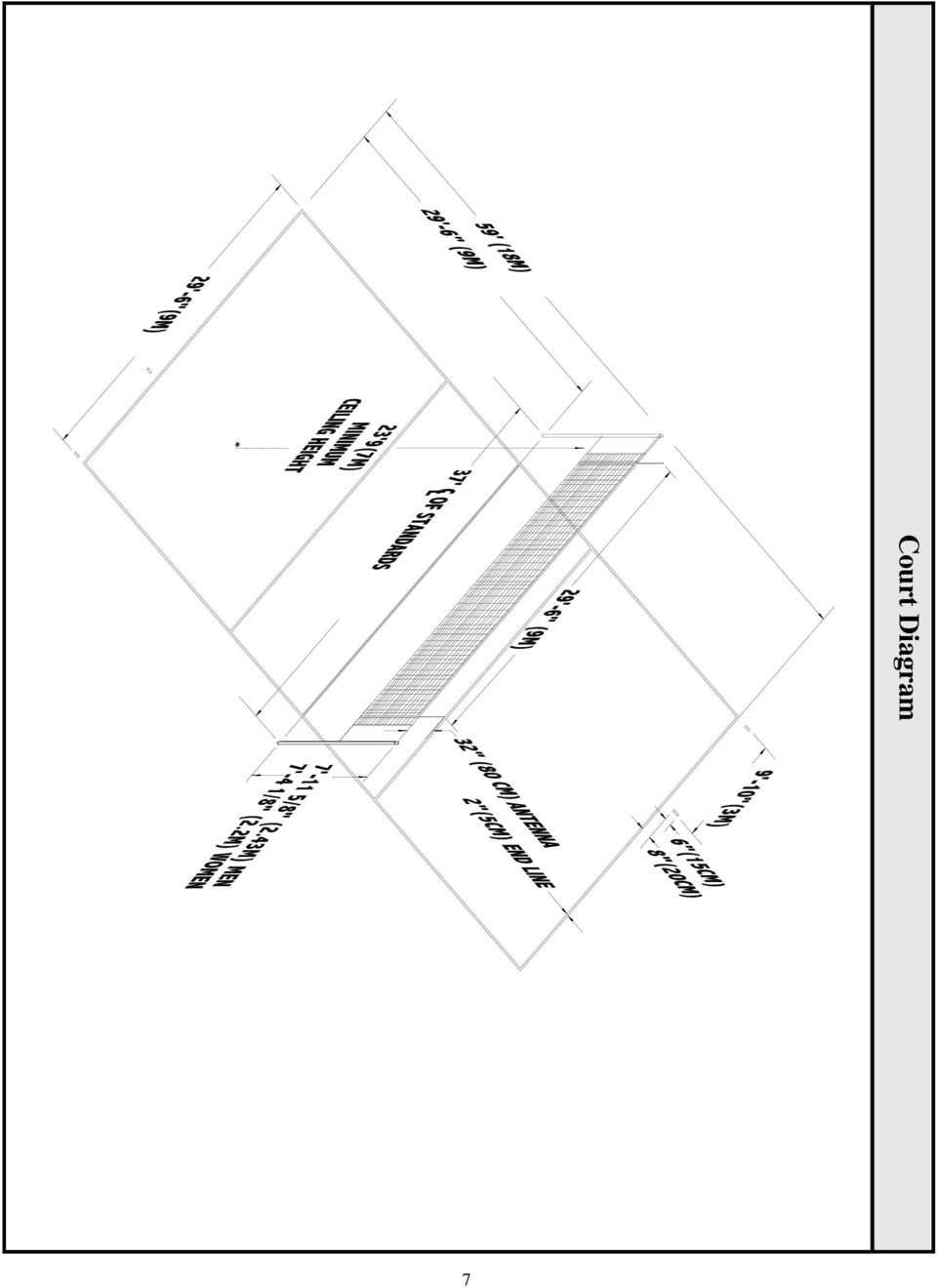
TABLE OF CONTENTS. I. TROUBLESHOOTING... 2 - Section 1.01: Common Problems/Solutions... 2
 BAL Accu-Slide System I. Table of Contents TABLE OF CONTENTS I. TROUBLESHOOTING... 2 - Section 1.01: Common Problems/Solutions... 2 II. GETTING STARTED... 5 - Section 2.01: Tools You Will Need... 5 - Section
INSTALLATION INSTRUCTIONS
 INSTALLATION INSTRUCTIONS PARTS REQUIRED Single QuickStand Parts A (1) QuickStand Unit B (1) Base Plate C (1) Platform D (1) Palm Support E (1) VESA Plate F (6) M8 x 18 mm Flat Head Machine Screws G (4)
UNPACKING AND ASSEMBLY
 UNPACKING AND ASSEMBLY Assembly Instructions Step 1. Open the two boxes and remove all the parts. Lay out the parts as shown below and read through the assembly instructions before beginning assembly.
4 in 1 Strength Station
 Revision 0 September 2010 4 in 1 Strength Station Owner s Manual Record Serial Number Here Platinum by Tunturi www.tunturi.com Date www.tunturi.com of Purchase 4 in 1 Strength Station Owner s Manual Instructions
GENUINE PARTS INSTALLATION INSTRUCTIONS
 GENUINE PARTS INSTALLATION INSTRUCTIONS DESCRIPTION: Illuminated Kick Plate APPLICATION: Rogue (2011) PART NUMBER: 999G6 GX010 KIT CONTENTS: Item A B C G H QTY 1 1 1 D 1 E 1 F 3 15 6 Description Kick Plate,
NBA Arena Portable System
 REQUIRED TOOLS AND MATERIALS: Two (2) Capable Adults Tape Measure Wood Board 6 x 6 (scrap) N53 W24700 South Corporate Circle Sussex, WI 53089 U.S.A. NBA Arena Portable System Sawhorse or Support Table
Navico-Northstar 2kW JRC Radar Package, Scanner Cable Removal and Replacement
 Navico-Northstar 2kW JRC Radar Package, Scanner Cable Removal and Replacement This work instruction describes the methods and means for which to remove and reinstall optional scanner cable configurations
READ CAREFULLY - FAILURE TO FOLLOW INSTRUCTIONS AND SAFETY RULES MAY RESULT IN SERIOUS INJURY
 Owner s Manual LSP16H LS3001 LS3002H LS3003 LSP21H LS3101 LS3102H LS3103 LSP24H LS3201 LS3102H LS3103 LSP28H LS3301 LS3302H LS3303 mainframe bundle H-unit bundle accessory box mainframe bundle H-unit bundle
Elo Touch Solutions Wall-mounting Kit for the 5501L IDS Touchmonitors
 Installation Manual Elo Touch Solutions Wall-mounting Kit for the 5501L IDS Touchmonitors SW602206 Rev B Table of Contents Chapter 1: Safety Warning... 3 Chapter 2: Kit Contents... 4 Included in Kit...
BUILT-IN DISHWASHER INSTALLATION INSTRUCTIONS
 BUILT-IN DISHWASHER INSTALLATION INSTRUCTIONS PLEASE READ COMPLETE INSTRUCTIONS BEFORE YOU BEGIN LEAVE INSTALLATION INSTRUCTIONS AND USER'S GUIDE WITH OWNER ALL ELECTRIC WIRING AND PLUMBING MUST BE DONE
STEADYfast Stabilizer Installation Notes Fifth Wheel and Travel Trailers 11/23/13
 STEADYfast Stabilizer Installation Notes Fifth Wheel and Travel Trailers 11/23/13 (See Supplemental Instructions for trailers with heavy duty round footplates and/or Power Leveling Systems) PHONE SUPPORT
TITAN Fuel Tanks. INSTALLATION INSTRUCTIONS G e n e r a t i o n V
 TITAN pt. no.: 02 0000 0143 Important: Please read these instructions carefully and completely before starting the installation. TITAN Fuel Tanks INSTALLATION INSTRUCTIONS G e n e r a t i o n V Extended
Product Notice. Safety Notice: Sales Hold
 Product Notice Ariens Company 655 W. Ryan St. Brillion, WI 54110 www.ariens.com Product Family: Ariens and Gravely 36 Power Brushes Subject: Sales Hold Inspect and Repair Dealer Action: SALES HOLD Do not
In-Ground Basketball System Owners Manual
 In-Ground Basketball System Owners Manual Customer Service Center N53 W4700 South Corporate Circle Sussex, WI 53089 U.S.A. Write Model Number From Box Here: WARNING! 3 Capable Adults REQUIRED TOOLS AND
INSTRUCTION. Industrial Sewing Machines. No. 010012. First published : June 1997 Second edition : March 2001
 INSTRUCTION Industrial Sewing Machines First published : June 1997 Second edition : March 2001 No. 010012 INTRODUCTION Thank you for your purchasing Kansai Special's DLR Series. Read and study this instruction
20000068 WIRELESS REMOTE ASSEMBLY, 24VDC, 1 TRANS,1 REC
 20000068 WIRELESS REMOTE ASSEMBLY, 24VDC, 1 TRANS,1 REC Fitment to MP-25 620 CR 4841, Haslet, TX 76052 Ph 817.439.1108 Fax 817.636.5675 www.machine-technologies.com Kit contents 1 Transmitter 2 button,
M2 Antenna Systems, Inc. Model No: KT34M2
 M2 Antenna Systems, Inc. Model No: KT34M2 10m f, MHz G, dbi F/B, db 28.0 7.3 18 28.2 7.3 23 28.4 7.4 25 28.6 7.5 24 29.2 7.6 20 15m f, MHz G, dbi F/B, db 21.0 6.9 19 21.1 6.9 22 21.2 7.0 24 21.3 7.0 24
Rollator Cane and Brake Replacement SAFETY SUMMARY (CONTINUED)
") Rollator Cane and Replacement Assembly, Installation and Operating Instructions SAVE THESE INSTRUCTIONS NOTE: Check ALL parts for shipping damage. If shipping damage is noted, DO NOT use. Contact Carrier/Dealer
Rollator Cane and Replacement Assembly, Installation and Operating Instructions SAVE THESE INSTRUCTIONS NOTE: Check ALL parts for shipping damage. If shipping damage is noted, DO NOT use. Contact Carrier/Dealer
SERVICE MANUAL. Corpus 3G. Seat system for electric wheelchair
 SERVICE MANUAL US Corpus 3G Seat system for electric wheelchair How to contact Permobil Head Office of the Permobil group Produced and published by Permobil AB, Sweden Version 4, 2014-07 Item No.: 205260-US-0
These Installation Instructions are valid for antennas in the following version:
 Installation Instructions 4 ft CompactLine Antennas (with E-Mount 250 km/h) SB, SBX NMT 560-05(e) These Installation Instructions are valid for antennas in the following version: Reflector Ø 1.2 m (4 ft)
1.8 CRANKSHAFT OIL SEALS
 SERIES 60 SERVICE MANUAL 1.8 CRANKSHAFT OIL SEALS An oil seal is fitted between each end of the crankshaft and the bores of the flywheel housing and gear case cover to retain the lubricating oil in the
Reachout Lock Replacement for Andersen 2-Panel and 4-Panel 400 Series Frenchwood Gliding, 200 Series Narroline, and Perma-Shield Gliding Patio Doors
 for Andersen 2-Panel and 4-Panel 400 Series Frenchwood Gliding, 200 Series Narroline, and Perma-Shield Gliding Patio Doors Thank you for choosing Andersen. For questions call 1-888-888-7020. For more information
Cable Drum Installation
 20 Cable Drum Installation COUNTERBALANCE None Shake the TorqueMaster spring tube gently to extend the winding shafts out about 5" on each side. For single spring applications, there will be no left hand
GPS AutoSteer System Installation Manual
 GPS AutoSteer System Installation Manual Supported Vehicles John Deere Sprayers 4720 4630 4730 4830 AutoTrac Ready PN: 602-0227-01-A LEGAL DISCLAIMER Note: Read and follow ALL instructions in this manual
Important: Please read these instructions carefully and completely before starting the installation. TITAN Fuel Tanks
 TITAN pt. no.: 03 0000 0120 Important: Please read these instructions carefully and completely before starting the installation. TITAN Fuel Tanks INSTALLATION INSTRUCTIONS G e n e r a t i o n V Extended
AM/FM ANTENNA RELOCATION KIT
 -J0 REV. 008-09-0 AM/FM ANTENNA RELOCATION KIT GENERAL Kit Number 766-09 Models This kit is used to relocate a fender-mounted AM/FM antenna to a Detachable Tour-Pak on specific model motorcycles. For model
Please Do Not Return This Product to the Store!
 MODEL NO. B400W GS60 BASKETBALL SYSTEM O W N E R ' S M A N U A L 1. Read this manual carefully before starting assembly. Read each step completely before beginning each step.. Some smaller parts may be
Micro Cart User's Guide
 Micro Cart User's Guide To take full advantage of the ergonomic features of your new Sun Mountain Micro Cart, please read the following information. SUN MOUNTAIN 1 Your Micro Cart has several innovative
758 Heavy-duty Ratchet Guy Wire Cutter
 INSTRUCTION MANUAL 758 Heavy-duty Ratchet Guy Wire Cutter Read and understand all of the instructions and safety information in this manual before operating or servicing this tool. Register this product
DB 18 & DB 18E Options
 DB 8 & DB 8E Options Assembly Manual Boom Truss Element Truss 6m Passive Inventory check DB 8 & DB 8 E Boom Truss Kit 7-004-0 QTY Part # Description 6 60-0045 /6 wire clips 4 60-0048 /6 Thimble 4 60-0044
Installation instruction do88 Intercooler for Volvo S40 / V50 / C30
 Installation instruction do88 Intercooler for Volvo S40 / V50 / C30 This instruction shows how to replace the OEM intercooler with our performance intercooler. 2. 3. 1. 4. 5. Part number: ICM-170 6. At
How to re-string & re-cable the Genesis Compound bow. Step by step, picture by picture Right hand models ONLY
 How to re-string & re-cable the Genesis Compound bow. Step by step, picture by picture Right hand models ONLY Introduction and Terminology Inspect all bows prior to use. Once a string or cable has become
Traditional Sonar and DSI Sonar Installation
 Traditional Sonar and DSI Sonar Installation This document covers the installation of the transducer and display unit installation, which includes connecting the unit to power and installing the unit on
Owner s Manual & Safety Instructions
 Owner s Manual & Safety Instructions Save This Manual Keep this manual for the safety warnings and precautions, assembly, operating, inspection, maintenance and cleaning procedures. Write the product s
ACTIVE & USER S GUIDE 483 N. FRONTAGE RD. NIPOMO, CA 93444 PHONE 805.929.3545
 M1 ACTIVE INSTALLATION MANUAL & USER S GUIDE 483 N. FRONTAGE RD. NIPOMO, CA 93444 PHONE 805.929.3545 1. P A C K A G E C O N T E N T S One (1) M1 Active pickup with battery installed One (1) pre-wired strapjack
Guidelines for Earthquake Bracing Residential Water Heaters
 Guidelines for Earthquake Bracing Residential Water Heaters Department of General Services Division of the State Architect In accordance with the Health and Safety Code Section 19215, the Division of the
Parts Required: Remove the Falcon Wiper Motor:
 INTERMITTENT WINDSHIELD WIPERS + 2 SPEEDS By Dick Harrington If you frequently drive your Falcon or Comet, sooner or later you will get caught in the rain. The first item of defense for good vision is
M113 VEHICLE FAMILY RUBBER TRACK INSTALLATION INSTRUCTIONS SOUCY TRACK SYSTEM 04-M113-1ENS (SPLIT IDLER) Litho d in Canada 1 04-M113-1ENS
 Litho d in Canada 1 04-M113-1ENS") M113 VEHICLE FAMILY RUBBER TRACK INSTALLATION INSTRUCTIONS (SPLIT IDLER) 1 # TABLE OF CONTENTS List of parts and tools................................................3 Installation of complete kit...................................................5
M113 VEHICLE FAMILY RUBBER TRACK INSTALLATION INSTRUCTIONS (SPLIT IDLER) 1 # TABLE OF CONTENTS List of parts and tools................................................3 Installation of complete kit...................................................5
SCION tc 2005-2008 COIL OVER SUSPENSION Preparation
 SCION tc 2005-2008 COIL OVER SUSPENSION Preparation Part Number: PTR11-21070 NOTE: Part number of this accessory may not be the same as the part number shown. Kit Contents: Item # Quantity Reqd. Description
OWNER S MANUAL Table Tennis Table Patent Pending
 OWNER S MANUAL Table Tennis Table Patent Pending Be sure to write your model number and serial number here for future reference. You can find these numbers printed on the bottom of the table. MODEL # T8179
DETACHABLE WINDSHIELD AND DOCKING HARDWARE KIT
 -J00 REV. 00-- DETACHABLE WINDSHIELD AND DOCKING HARDWARE KIT GENERAL Kit Number -A, 0-, -, 0-, -, - 0, -0 Models These kits fit and later FXST, FXSTB, FXSTC, and and later FXDWG Harley-Davidson model
BILLET HEADLAMP WITH SHORT/TALL MOUNTS
 -J099 REV. 00-0- BILLET HEADLAMP WITH SHORT/TALL MOUNTS GENERAL Kit Number 9-0, 9-0 Models Kit 9-0 is a -/ inch headlamp and kit 9-0 is a -/ inch headlamp. Both kits will fit the models listed in Table.
Written By: Walter Galan
 ipad 2 GSM Rear Camera Replacement Replace the rear camera in your ipad 2 GSM. Written By: Walter Galan INTRODUCTION Use this guide to replace a broken rear camera. TOOLS: ifixit Opening Picks set of 6
Mounting Tripod Kit Installation Manual
 Mounting Tripod Kit Installation Manual For use with Davis s wireless and cabled Vantage Pro2 weather stations, the Mounting Tripod simplifies installation. The tripod supports the Integrated Sensor Suite
UPLIFT Height Adjustable Standing Desk (T-Frame) DIRECTIONS FOR ASSEMBLY AND USE - - ALSO - - Watch our assembly video
 DIRECTIONS FOR ASSEMBLY AND USE - - ALSO - - Watch our assembly video") UPLIFT Height Adjustable Standing Desk (T-Frame) DIRECTIONS FOR ASSEMBLY AND USE - - ALSO - - Watch our assembly video http://bit.ly/9ywwh! CAUTION MAKE SURE NO OBSTACLES ARE IN THE DESK S PATH AND ALL
UPLIFT Height Adjustable Standing Desk (T-Frame) DIRECTIONS FOR ASSEMBLY AND USE - - ALSO - - Watch our assembly video http://bit.ly/9ywwh! CAUTION MAKE SURE NO OBSTACLES ARE IN THE DESK S PATH AND ALL
Assembly and Usage Instructions
 Assembly and Usage Instructions A Product 5885 West Van Horn Tavern Road Columbia, MO 65203 www.caldwellshooting.com Instruction #1001667 Limited Warranty Every Caldwell product is warrantied to be free
FRONT BUMPER INSTALLATION INSTRUCTIONS 2007-2011 DODGE / MERCEDES SPRINTER
 Aluminess Products Inc 9402 Wheatlands Ct. #A Santee, CA 92071 619-449-9930 FRONT BUMPER INSTALLATION INSTRUCTIONS 2007-2011 DODGE / MERCEDES SPRINTER Please read before beginning Stainless steel hardware
AstroSystems Digital Setting Circles for Zhumell, GSO, Apertura and Astro-Tech
 AstroSystems Digital Setting Circles for Zhumell, GSO, Apertura and Astro-Tech Components 1 Sky Commander Digital Setting Circle Computer 2 Encoders 10,000 step 1 Sky Commander Digital Setting Circle Manual
Slide the new steering column shaft through the steering column from the driver compartment.
 Slide the new steering column shaft through the steering column from the driver compartment. Push the column shaft through the steering column until the machined end is out past the column lower bushing.
WARNING! DO NOT ATTEMPT TO INSTALL THIS KIT IN A POWERED CONVEYOR.
 Model: Document Number: 64058111 Kit Number: 64058112 Revision: 02 Description: Release Date: 04/08 Introduction This kit allows a PS90 scale to be integrated into a standard gravity conveyor. The kit
Operator s Manual EVENTER 20 / 25 Series Lifts
 Operator s Manual EVENTER 20 / 25 Series Lifts May 2013! Before operating this lift, read and understand this Operator s Manual. Become familiar with the potential hazards of this unit. Call SUMNER should
I BEAM TRACK INSTALLATION
 PDQ 0/700 FESTOON SYSTEM INSTALLATION AND MAINTENANCE INSTRUCTIONS INTRODUCTION The PDQ Festoon System was designed to run on one of three sizes of I-beams: S x., S8 x 8. and S x.. System trolleys must
Andersen Electric Window Opener for Andersen Awning and Roof Windows
 W A Electric Window Opener Electric Window Opener for Awning and Roof Windows Congratulations! You have just purchased one of the many fine products. For ease of installation and continued enjoyment of
AM/FM ANTENNA KIT (TOUR-PAK MOUNT)
") -J077 REV. 008-0-0 AM/FM ANTENNA KIT (TOUR-PAK MOUNT) GENERAL Kit Number 7-98A Models For model fitment information, see the P&A Retail Catalog or the Parts and Accessories section of www.harley-davidson.com
-J077 REV. 008-0-0 AM/FM ANTENNA KIT (TOUR-PAK MOUNT) GENERAL Kit Number 7-98A Models For model fitment information, see the P&A Retail Catalog or the Parts and Accessories section of www.harley-davidson.com
HT-0095 Mini PV Receptacles 22-32 AWG Crimping Hand Tool. Tool P/N HT-0095
 HT-0095 Mini PV Receptacles 22-32 AWG Crimping Hand Tool Tool P/N HT-0095 FCI MANUAL P/N 415988-001 Issued: Date (03/12/99) Page 1 of 18 HT-0095 Issued: Date (03/12/99) Page 2 of 18 Introduction Table
Fiberstars Lighted Laminar Flow Fountain Installation Manual
 Fiberstars Lighted Laminar Flow Fountain Installation Manual 79-15037-00 REV Xx http://www.fiberstars.com Page 1 of 8 SAVE THESE DIRECTIONS! These directions are provided to ensure the proper installation
S&G Model 2937 Group 1 Combination Lock
 Installation and Combination Changing Instructions S&G Model 2937 Group 1 Combination Lock NOTE: READ COMPLETE INSTRUCTIONS BEFORE INSTALLATION These instructions should be followed when installing the
MGB Chrome Bumper Conversion
 MGB Chrome Bumper Conversion Installation Instructions For 1974 1/2-1980 MGB This kit requires cutting, welding, and painting. Professional installation recommended. Note: Every MGB body is slightly different
PARTS NEEDED FOR CONVERTING FROM LP TO NG
 1 6 7 8 3 5 4 10 9 2 PARTS NEEDED FOR CONVERTING FROM LP TO NG Number Description 1 30" NG Manifold 2 NG side burner valve 3 NG Regulator 4 Rear I/R NG orifice 4 Rear I/R NG orifice 5 Side burner NG orifice
INSTALLATION MANUAL. Installation Instructions
 INSTALLATION MANUAL Power-Pole Signature Series Shallow Water Anchor Installation Instructions CAUTION: Read this instruction manual carefully. Become familiar with the controls and know how to operate
R O A D M A S T E R, I N C.
 R O A D M A S T E R, I N C. ROADMASTER, Inc. 6110 NE 127th Ave. Vancouver, WA 98682 8 7 1 6 15 28 1 2 "± 1 2 " MOUNTING BRACKET KIT 3 2 10 14 4 5 9 360-896-0407 fax 360-735-9300 www.roadmasterinc.com Item
TRANS-05, Torque Tube Removal, Rebuilding, and Installation
 TRANS-05, Torque Tube Removal, Rebuilding, and Installation Tools Metric Wrench Set Metric Socket Set Jack Stands (6 minimum) Floor Jack 8mm Cheesehead socket (also referred to as 12 point internal socket
Little British Car Co.
 Little British Car Co. 29311 Aranel, Farmington Hills, MI 48334-2815, USA Tel: 248 489 0022 or 800 637 9640 Fax: 248 489 9665 On the web at: www.lbcarco.com E-mail: [email protected] MGB Tube Rear Shock
Guidelines for Earthquake Bracing of Residential Water Heaters
 Guidelines for Earthquake Bracing of Residential Water Heaters Department of General Services Division of the State Architect 1102 Q Street, Suite 5100 Sacramento, CA 95814 Phone: (916) 324-7099 Fax: (916)
Post Mount Light Installation*
 Post Mount Light Installation* *For the general installation of most Post Mount Spotlights, many vehicles may need slight modifications to these instructions. You will need the following tools: High torque
INSTALLATION INSTRUCTIONS FOR 2006-2009 VW MK5
 CI100018 INSTALLATION INSTRUCTIONS FOR 2006-2009 VW MK5 Rabbit, Jetta 2.5L These instructions are applicable to vehicles equipped with either manual or automatic transmissions Thank you for choosing to
EXPLORE 4-Leg Teaming Table with Screen Share Assembly Instructions
 EXPLORE 4-Leg Teaming Table with Screen Share Monitor Display Requirements: your flat panel display must confirm to the following requirements. y With the stand removed, the monitor must not exceed 40
SCION FR-S 2013 - PERFORMANCE AIR INTAKE Preparation 2.0L F-4
 Preparation 2.0L F-4 Part Number: PTR03-18130 Please see Page 12 for important Care and Maintenance information! Kit Contents Item # Qty. Service Part # Description 1 1 PTR03-18130-AC TRD Air Box Base
Installation Guide Hoops (IHS) Cable
 Cable") Installation Guide Hoops (IHS) Cable Thank you for selecting a DuctSox System. This guide will be helpful for the installation of a Hoops (IHS) Cable System. Sections of fabric will be labeled, assembled,
Installation Guide Hoops (IHS) Cable Thank you for selecting a DuctSox System. This guide will be helpful for the installation of a Hoops (IHS) Cable System. Sections of fabric will be labeled, assembled,
HOME GYM. Model. Retain This Manual for Reference OWNER'S MANUAL. www.hyper-extension.com
 NOTE: Please read all instructions carefully before using this product Table of Contents Safety Notice www.hyper-extension.com HOME GYM 50036 Hardware Identifier Assembly Instruction Parts List Warranty
PLASTIMO JIB REEFING SYSTEMS S-SERIES 406-S 608-S 810-S
 PLASTIMO JIB REEFING SYSTEMS S-SERIES 406-S 608-S 810-S GB ASSEMBLY INSTRUCTIONS FOR S-SERIES 406-S 608-S 810-S I N D E X Technical specifications of 406-S, 608-S, 810-S 3 Description of specific parts
Installation Instructions: (Part # SB76880) XRC Armor Front Fender Kit
 XRC Armor Front Fender Kit") WARNING: Check with Local and State laws before installing this accessory! NOTE: Carefully read entire instructions thoroughly before attempting to install this part. Parts Included: Qty Parts Included:
WARNING: Check with Local and State laws before installing this accessory! NOTE: Carefully read entire instructions thoroughly before attempting to install this part. Parts Included: Qty Parts Included:
3. Loosen 3 x grub screws in the Dec end cap and unscrew the cap and counterweight shaft. NEQ6 Belt Modification Kit.
 NEQ6 Belt Modification Kit. Thank you for your purchase. Please read these instructions fully before fitting. Your package should contain 2 off 47 & 2 off 12 tooth aluminium pulleys 2 off belts 6mm wide
Transducer Installation
 Transducer Installation This document covers the installation of all 83/200kHz, 50/200kHz and Downscan transducers using transom and shoot-thru hull installation methods, where applicable. This manual
LG G5 Chassis Brace Gen 5 Camaro THE MOST POWERFUL HEADERS ON THE PLANET Brought to you by LG Motorsports 972-429-1963
 LG G5 Chassis Brace Gen 5 Camaro THE MOST POWERFUL HEADERS ON THE PLANET Brought to you by LG Motorsports 972-429-1963 Thank you for purchasing LG Motorsports products for your Gen 5 Camaro. Parts Inventory:
Written By: Walter Galan
 ipad 2 GSM LCD Replacement Replace the LCD in your ipad 2 GSM. Written By: Walter Galan INTRODUCTION Use this guide to replace a broken LCD. TOOLS: iopener (1) Phillips #00 Screwdriver (1) Plastic Opening
Quick Start Guide See Inside for Use and Safety Information
 3 rd Generation Personal 3D Printer Quick Start Guide See Inside for Use and Safety Information The USB Mass Storage Device Contains the User Guide and Quick Start Guide in other Languages Congratulations
Please Do Not Return This Product To The Store!
 O W N E R ' S MODEL NO. M A N U A L B0F B0W CV60 BASKETBALL SYSTEM. Read this manual carefully before starting assembly. Read each step completely before beginning each step.. Some smaller parts may be
Coaxial Cable Installation Accessories
 Installation Instructions Bulletin 37608 Coaxial Cable Installation Accessories Hoisting Grips for Coaxial Cable and Elliptical Waveguide READ ALL WARNINGS AND INSTRUCTIONS BEFORE INSTALLATION Antenna
COOPER S PULLEY UPGRADE KIT INSTALLATION INSTRUCTIONS PART NUMBER NME5011
 COOPER S PULLEY UPGRADE KIT INSTALLATION INSTRUCTIONS PART NUMBER NME5011 Below are instructions for the Mini Mania Pulley Upgrade Kit, Part Number NME5011. Please take all necessary precautions for working
BODY-12, Door Handle - Removal, Installation, and Adjustment
 Introduction BODY-12, Door Handle - Removal, Installation, and Adjustment There are many different procedures floating around describing how to replace the door handles on a 944 and every one of them will
ScreenLogic Wireless Connection Kit. Installation Guide. pool/spa control system
 pool/spa control system ScreenLogic Wireless Connection Kit Installation Guide P/N 520663 - Rev B 8 Technical Support Contact Technical Support at: Sanford, North Carolina (8 A.M. to 5 P.M.) Phone: (800)
Step 1. Item 6. Item 1
 Voltage Regulators QD3/T350 Motor Replacement Kit Kit Number 57A63675100B Service Information S225-50-35 Contents General..................................... 1 Parts Supplied...............................
Weatherproofing Kit for Connectors and Antennas
 Weatherproofing Kit for Connectors and Antennas Butyl rubber tape The kit can be used for one or more connections depending on the configuration and cable type as follows: / (9-mm) plastic tape (-mm) plastic
RayClic Connection System Installation Instructions
 RayClic Connection System Installation Instructions Description RayClic-S Splice Kit RayClic-T Tee and End Seal Kit RayClic-X Cross and End Seal Kit These kits are for use with Raychem IceStop, XL-Trace
Time needed: ~3h for lid replacement only. Add 1h for operation harness in lid and ~2h more for installing drive unit and cable harness in trunk.
 DIY for replacing trunk lid and/or retrofitting electrical operation of trunk lid. This document is meant to be a support and give advice on the procedure but I will take no responsibility for any damage
OWNER S MANUAL. FOOTWORKS tm Faucet Controller. Foot Operated Faucet Control Valves for Commercial Sinks
 OWNER S MANUAL for FOOTWORKS tm Faucet Controller Foot Operated Faucet Control Valves for Commercial Sinks - 1 - Introduction Congratulations on your purchase of a FOOTWORKS tm Faucet Controller, an engineered
Mini multi-purpose sewing machine
 TROUBLESHOOTING Problem Problem cause Amendment No power or the machine runs slowly Batteries are installed incorrectly Batteries are low Reinstall the batteries making sure they are the correct way around
Indoor/Outdoor Color Camera with Built-in 2.4 GHz Wireless Transmitter, plus X10 controlled power supply, and Video Receiver.
 Indoor/Outdoor Color Camera with Built-in 2.4 GHz Wireless Transmitter, plus X10 controlled power supply, and Video Receiver. OWNER'S MANUAL VR36A XC18A XM13A MODEL VK69A (INCLUDES XC18A CAMERA, XM13A
2006 HEADSHOK Service Video #1
 LEFTY SPEED DLR DAMPING CARTRIDGE This document explains how to properly remove, disassemble, inspect, reassemble and reinstall the Lefty Speed DLR2 damping cartridge. It is a document to be used in conjunction
1000-LB. TRAILER JACK OWNER S MANUAL
 1000-LB. TRAILER JACK OWNER S MANUAL WARNING: Read carefully and understand all INSTRUCTIONS before operating. Failure to follow the safety rules and other basic safety precautions may result in serious
SIMPLEX UNICAN LOCKS CHANGING THE CODE / COMBINATION 900 Series 1000 Series L1000 Series LP1000 Series EE1000 Series 2000 Series 2015 Series
 SIMPLEX UNICAN LOCKS CHANGING THE CODE / COMBINATION 900 Series 1000 Series L1000 Series LP1000 Series EE1000 Series 2000 Series 2015 Series 2400/2500 Series 3000 Series 3100 Series Simplex 5000 Series
How to remove, replace and tighten accessory belts for a second generation (NB, 1999-2005 ) Mazda Miata MX-5
 Mazda Miata MX-5") How to remove, replace and tighten accessory belts for a second generation (NB, 1999-2005 ) Mazda Miata MX-5 If your Miata is squealing loudly either when you engage the air conditioner, turn on the car,
How to remove, replace and tighten accessory belts for a second generation (NB, 1999-2005 ) Mazda Miata MX-5 If your Miata is squealing loudly either when you engage the air conditioner, turn on the car,
Triple Threat 3-in-1 Game Table 3 IN 1 GAME TABLE
 NG0M Triple Threat 3-in- Game Table 3 IN GAME TABLE Thank 3 in Y Game Table Thank you for your purchase of our product. We work around the clock and around the globe to ensure that our products maintain
18974 (736) Singer No. 20-2. SINGER No. 20-2 ELECTRIC SEWING MACHINE INSTRUCTION MANUAL
 Singer No. 20-2. SINGER No. 20-2 ELECTRIC SEWING MACHINE INSTRUCTION MANUAL") SINGER No. 20-2 ELECTRIC SEWING MACHINE INSTRUCTION MANUAL Next Page Main Parts Accessories To start the Motor To Stop the Motor To Change the Speed Needles and Thread Relative Sizes of Needle and Thread
SINGER No. 20-2 ELECTRIC SEWING MACHINE INSTRUCTION MANUAL Next Page Main Parts Accessories To start the Motor To Stop the Motor To Change the Speed Needles and Thread Relative Sizes of Needle and Thread
PORTABLE PA SYSTEM #1 LAST UPDATED: FEBRUARY 2011
 PORTABLE PA SYSTEM # LAST UPDATED: FEBRUARY 20 The portable PA system has been created to offer student groups an easy to use solution for self-operated sound needs. The system has the capability for:
Table of Contents WARNING SYMBOLS AND DEFINITIONS
 Table of Contents SAFETY INSTALLATION OPERATION MAINTENANCE Safety... 2 Specifications... 4 Installation... 5 Operation... 8 WARNING SYMBOLS AND DEFINITIONS Maintenance... 9 Parts List and Assembly Diagram...
RayClic Connection System Installation Instructions
 F M -W RayClic Connection System Installation Instructions RayClic WARNING: Shock Hazard 718K Pipe Heating Cable with HWAT, IceStop, also Listed De-icing and and XL-Trace heating Snow Melting Equipment
EZ-48-3AB-125-35 Weather Station Mounting Tripod and Mast
 EZ-48-3AB-125-35 Weather Station Mounting Tripod and Mast EZ-125-35M 35 Mast Extension (Optional) EZ-125-SK Stake Kit (Optional) EZ-46-3 Tar Pad Kit (Optional) EZ-GWA Guy Wire Kit (Optional) Ambient Weather
SLACK PERFORMANCE KARTS
 SLACK PERFORMANCE KARTS SET UP GUIDE Thank you for purchasing a 2013 Slack Axiom Chassis. Performance Mfg. strives to provide you with the very best chassis and components on the market today. Your satisfaction