Thermal Resistance, Power Dissipation and Current Rating for Ceramic and Porcelain Multilayer Capacitors
|
|
|
- Maud Howard
- 9 years ago
- Views:
Transcription
1 Thermal Resistance, Power Dissipation and Current Rating for Ceramic and Porcelain Multilayer Capacitors by F. M. Schaubauer and R. Blumkin American Technical Ceramics Reprinted from RF Design Magazine, May/June and July/August, 1981

2 INTRODUCTION The information in this article makes it possible for a circuit designer to calculate the temperature rise of any multilayer capacitor*. The method used for calculation of the temperature rise of a capacitor is quite similar to the techniques that are universally used for transistors. The theoretical determination of the temperature rise of a capacitor due to AC current flowing through it is a difficult task. Equipment designers, when faced with the problem, require parameters that are generally not available from the capacitor manufacturer, such as ESR (Equivalent Series Resistance), and Θ (Thermal Resistance), etc., of the capacitor. If the ESR and current are known, the power dissipation and thus, the heat generated in the capacitor can be calculated. From this, plus the thermal resistance of the capacitor and its external connections to a heat sink, it becomes possible to determine the temperature rise above ambient of the capacitor. Current distribution is not uniform throughout a monolithic capacitor, since the outermost plates (electrodes) carry less current than the inner electrodes. This is shown in Figure 1 for an 8 electrode capacitor. From the figure, it can be seen that there are 7 capacitor section s (Since for N electrodes there (N-1) capacitor sections). If the total current into the capacitor is Ι, the current for each section is Ι / 7. For an outermost electrode, Ι / 7 is actually the current carried by the electrode. For all other electrodes, the current is 2 ( Ι / 7 ) since the electrodes carry the current for two sections. Furthermore, the current is not the same at each point on the electrode. For electrode 8, the current is Ι /7 at the left or termination end and zero at the right or open end. The current distribution is approximately as shown in Figure 1. As a result of this current distribution, the heat generated is not uniform within the capacitor. For an actual multilayer capacitor, there are connection resistances between the electrodes and the terminations, which cause heat generation. This effect depends upon the quality of manufacture of the capacitor. Some manufactures have fairly high connection resistances, whereas others have connection resistances that are undetectable. This article assumes a capacitor manufactured with no defects, i.e. zero connection resistances, and it also assumes that the temperature difference across the thickness of the dielectric between the electrodes is negligible, i.e. less than 1 C. Figure 1. The validity of the assumptions has been checked experimentally by measurements of ESR and temperature rise vs. RF current for various capacitor values at a frequency of 30 MHz. CAPACITOR RF CURRENT RATINGS There are two criteria for maximum current rating. The first criterion is due to the rated working voltage of the capacitor and is discussed below. The RF current corresponding to this voltage is: where, Ι p = Vpeak V DC X c Ιp = Peak RF current V peak = Rated Working voltage of the capacitor V DC = DC Voltage across the capacitor X c = Reactance of the capacitor at frequency of operation *Manufactured by American Technical Ceramics Corp. (1) 2
, and Θ (Thermal")
3 The RF current must not exceed the value from Equation 1. The second criterion is due to the temperature rise caused by power dissipation, (discussed in succeeding paragraphs). In most applications, multilayer capacitors are soldered into the circuit or fastened into place by use of a conductive epoxy. Since the maximum temperature of the solder normally used on the terminations of the capacitor is 190 C; 125 C was chosen as the maximum for one series of capacitors.* This ensures the user that the temperature will not exceed the softening temperature of the epoxy or solder. This temperature then determines the maximum power dissipation and in turn, the maximum current, if the capacitor ESR is known. Figure 2. WORKING VOLTAGE RATING The criterion for the maximum voltage rating depends upon the voltage breakdown characteristics of the capacitor. The voltage breakdown rating is normally some fraction of the actual internal breakdown voltage. For one series of porcelain dielectric capacitors,** the breakdown voltage exceeds 1000 volts/mil of dielectric thickness and is virtually independent of temperature. Other dielectrics, such as barium titaniate and many NPO s have much lower breakdown voltages/mil. In some situations, the surface breakdown or flash-over voltage rather than the actual internal breakdown voltage is the determining factor. In these cases, the flash-over determines the rated working voltage. The factors affecting flash-over voltage include surface length of path, surface contamination and environmental conditions. CURRENT RATING DUE TO POWER DISSIPATION Before launching into a thermal analysis of the multilayer capacitor, it is advisable to review some basic thermal principles: HEAT TRANSFER The equivalent of Ohm s Law for heat transfer is: (See Figure 2.) where, A = Cross section plane perpendicular to heat (cm 2 ) P d = Power dissipated (watts) at area A T 2 = Temperature ( C) of cross section area A (perpendicular to heat flow) T 1 = Temperature ( C) at a cross section area at a distance L from area A L = Length of path (cm) between areas Θ = Thermal resistance of path across length L ( C/W) Pd = (T2 T1) (Watts) (2) Θ where, Pd is analogous to electrical current, (T 2 T 1 ) is analogous to electrical voltage difference and Θ is analogous to electrical resistance. THERMAL RESISTANCE The thermal resistance for a given material and dimensions can be calculated: Θ = L ( C/W) (3) 4.186KA where, K = Thermal conductivity coefficient of the material [gm cal/( C)(sec)(cm)] L = length of path (cm) A = Area perpendicular to path (cm 2 ) Note: When the thermal conductivity is given in watts/( C)(cm), multiply by.2389 to obtain gm cal/( C)(sec)(cm). *ATC 100 series **ATC Porcelain dielectric capacitors. 3

4 Figure 3. To provide a useful thermal model for calculating the power dissipation of a multilayer capacitor, the following constraints are applied: a) The thermal resistance of the terminations are negligible. This is accomplished by selection of the proper termination material, control of it s thickness, uniformity of termination deposition and tight process control. b) Heat is removed by conduction mode only, via the terminations of the capacitor to external leads or transmission lines, etc. Radiation and convection are disregarded. This constraint provides an additional safety factor in current ratings. Figure 4. c) The thermal conductivity is constant over the temperature range of 25 C to 125 C. The thermal circuit for a multilayer capacitor is complicated because there are many parallel thermal paths. Since the current varies over the length of the capacitor, the power dissipation is not concentrated at any one point in the capacitor, but is distributed throughout the length of the capacitor. To simplify this situation the equivalent thermal circuit is derived which substitutes a single lumped power dissipation source (heat generator) at the central plane of the capacitor and a lumped thermal resistance from this central plane to each of the capacitor terminations. Figure 3 illustrates the derivation of this thermal equivalent circuit for a two electrode capacitor. A strip dx is selected a distance x from termination 1. HEAT GENERATION (CENTERAL) PLANE TERMINATION 1 T 1 The power dissipation in the electrodes in this strip is calculated from i 2 R x d x, where i is the current in one electrode at plane x and R x is the resistance per unit length of the electrode. Similarly the power dissipation in the dielectric in this strip is calculated from the dissipation factor and the current. The dissipation factor of the dielectric is constant as a function of x. The total power dissiption in the strip dx is P x and is the sum of the two above power dissipations. The thermal resistance Θ 1x and Θ 2x from the strip to the terminations consist of parallel electrode and dielectric paths and are calculated from the form: d m dl ms T in ms d dl m T 2 TERMINATION 2 Θ d = Thermal resistance of dielectric from Heat Generation Plane to a termination ( C/W) Θm = Thermal resistance of parallel combination of all electrodes from Heat Generation Plane to the connected termination for length = L + l ( C/W) 2 Θms = Thermal resistance of parallel combination of all short electrodes from Heat Generation Plane to unconnected end of electrodes for a length = L + l ( C/W) 2 Θ dl = Thermal resistance of parallel combination of dielectric in series with short electrodes for a length = l ( C/W) T in = Temperature of Heat Generation Plane ( C) T 1 = Temperature of termination 1 ( C) T 2 = Temperature of termination 2 ( C) 4
 Heat is removed by conduction mode only, via the terminations of the capacitor to external leads or transmission lines, etc. Radiation and convection are disregarded.")
5 Figure 5. where, Θ 1 = Θ 2 =2Θ cap = 1 ( 1 ) + ( 1 ) + ( 1 ) Θ d Θ m Θ ms + Θ dl (4) Θ cap = Θ1 Θ2 Θ1 + Θ2 (5) Θ cap = Thermal resistance of capacitor from Heat Generation Plane to both terminations ( C/W) x Θ 1x = or Θ 2x = L + l x 4.186KA 4.186KA If now the terminations 1 and 2 are connected together thermally but not electrically, i.e., the temperature of termination 1 is the same as the temperature of termination 2, then the temperature rise at plane x of the capacitor can be calculated from the expression: T X = P Θ X 1X Θ 2X Θ 1X + Θ 2X where: T X = Temperature rise above T 1 or T 2 ( C) Θ 1X = f 1 (x) = Thermal resistance from plane x to termination 1 ( C/W) Θ 2X = f 2 (x) (L + l - x) = Thermal resistance from plane x to termination 2 ( C/W) P x = f 3 (R x,x,dx) = Power dissipated in metal electrodes and dielectric in width dx located at plane x If T X is integrated, an expression is obtained in a form as follows: T = f ( P d Θ 2) where: Θ = Thermal resistance from central plane to termination 1 and termination 2 ( C) P d = Total power dissipated in capacitor (watts) and thus, T=Temperature rise of central plane above termination ( C). This permits the establishment of the equivalent circuit with all the power dissipation in the central plane and thermal resistances from that plane to each of the terminations. The validity of this result is also apparent from the symmetry of the structure of the capacitor on either side of the central plane. This symmetry is also true for the capacitor s power dissipation and thermal resistances. Figure 4 is the thermal equivalent circuit for the two electrode capacitor in Figure 3. From Figure 4, one can see that there are two equal thermal paths from the central plane to each of the terminations. For each path there are three thermal resistances in parallel. One is metal, the second is dielectric and the third is metal in series with a small length (l) of dielectric. 5

6 of the electrodes (wh) and the other is through the area of the dielectric (WH 2wh). If there are N elec trodes, these become Nwh and (WH Nwh). If termination 1 is thermally connected, but not necessarily electrically connected to termination 2, T 1 becomes equal to T 2. This is equivalent to folding Figure 4 at the Heat Generation Plane and connecting termination 1 to termination 2. The thermal resistance of the capacitor is thus developed as shown in Figure 5. Using the equivalent circuit of Figure 5 and Equations 3, 4 and 5 the thermal resistance of ATC 100A 1.0 pf and 100 pf capacitors and ATC 100B 1.0 pf, 100 pf and 1000 pf capacitors can be calculated. The results are shown in Table 1. POWER RATING As previously stated, the allowable power dissipation can be determined by the knowledge of the thermal resistance Θ cap, the equivalent series resistance ESR of the capacitor, the maximum allowable internal temperature and the maximum temperature that solder or epoxy on the termination can tolerate without destruction. The simplified equivalent thermal circuit, when the capacitor terminations are connected to an infinite heat sink, is shown in Figure 6. The thermal equation for the circuit in Figure 6 is given by: Θ cap (P d ) = (t in T 1 ) (6) and is plotted in Figure 7. If the vertical scale name is changed from power dissipation Pd to power dissipation allowed Pda, this curve is really a maximum power rating curve for the capacitor, where the allowed internal temperature Tin is equal to T 1max = 125 C. For example, if the heat sink and therefore, the terminations are set E L E C T R O D ES D IE L E C T R I C CAP Θ cap Calculated from Electrode and Dielectric Dimensions and Thermal Conductivity SERIES 100A 100B ELECTRODES Cap Value (pf) N = Number of Electrodes L (cm) l (cm) A m (cm 2 ) N A m (cm 2 ) K m gm cal/(sec)( C)(cm) Θ m ( C/W) Θ ms ( C/W) Table 1. DIELECTRIC L + l (cm) A cap (cm 2 ) A d K d 0.03 gm cal/(sec)( C)(cm) Θ d ( C/W) Θ dl ( C/W) CAPACITOR Θ cap ( C/W) Figure 6. where, subscript d = dielectric subscript m = metal electrode Equations used in calculation are from equations 3, 4 and 5: Θ m = 0.5 (L + l) Θ d = 0.5 (L + l) Θ ms = 0.5 (L - l) 4.186K m ( NA m ) 4.186K d A d 4.186K m ( NA m ) 2 2 Θ d = l Θ cap = K d ( NAm ) ( 1 )+( 1 )+( 1 ) 2 Θm Θd Θms + Θd l Am = wh Acap = WH Ad = WH whn NOTE: Θcap PLAYS THE SAME ROLE FOR CAPACITORS AS Θjc PLAYS FOR TRANSISTORS P d = Power dissipated in capacitor (watts) T A = Ambient temperature ( C) = INFINITE HEAT SINK (a mass at a temperature that cannot be changed, regardless of the amount of heat pumped into it) 6

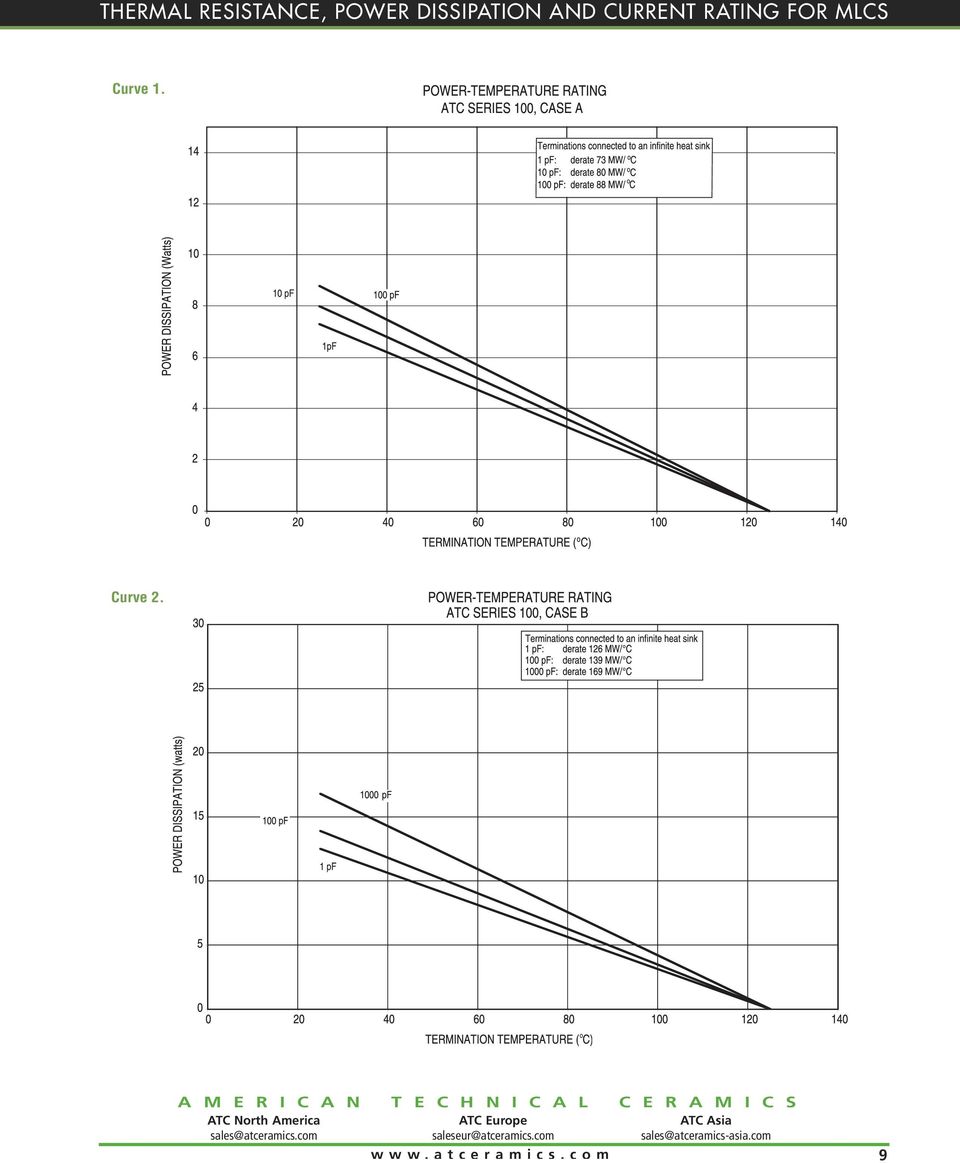
7 Figure 7. where, at T A = T 1 = 25 C; P d max = ( 1 ) T in Θ cap and at P d = 0; T 1max = 125 C slope = Pd = 1 T1 Θcap where, P da = Power dissipation allowed for an internal temperature of T 1max to 50 C, then the internal temperature will be 125 C for a P da of 7.2 watts. This is the particular condition shown by the dotted lines in Figure 7. Similarly, one can determine the power rating of the capacitor for any given heat sink temperature of termination temperature. It should be stressed that this equivalent circuit and curve is for the specific condition where terminations are connected to an infinite heat sink. Values of P da for actual capacitors are plotted in power temperature rating Curves 1 and 2. Curve 6 provides power dissipation and thermal resistance for both 100A and 100B, for capacity values between 1.0 pf and 1000 pf. The allowable power dissipation for the capacitors in Table 1 with an infinite heat sink at 25 C connected to the termination is given in Table 2. The thermal situation taking into account external thermal resistance is shown in Figure 8. Assuming that T 1 = T 2, the thermal circuit becomes Figure 9. The thermal circuit is described by: (8) P d Θ cap + P d Θ x = T in T A Since Tin is a maximum of 125 C and both Θ cap and Θ x are known, the circuit designer can solve for the maximum Figure 8. Figure 9. 2 cap.. EXTERNAL T 1 T X 1 HEAT GENERATION PLANE T 1 2 cap T 2 X 2 X 2 CAPACITOR THERMAL PATHS (MICROSTRIP, P.C. BOARD, CONDUCTOR, ETC. HEAT SINK Θ x1 = External thermal resistance, from termination 1 to heat sink ( C/W) Θ x2 = External thermal resistance, from termination 2 to heat sink ( C/W) where, Θ x = Θ x1 Θ x2 Θ x1 + Θ x2 (7) 7

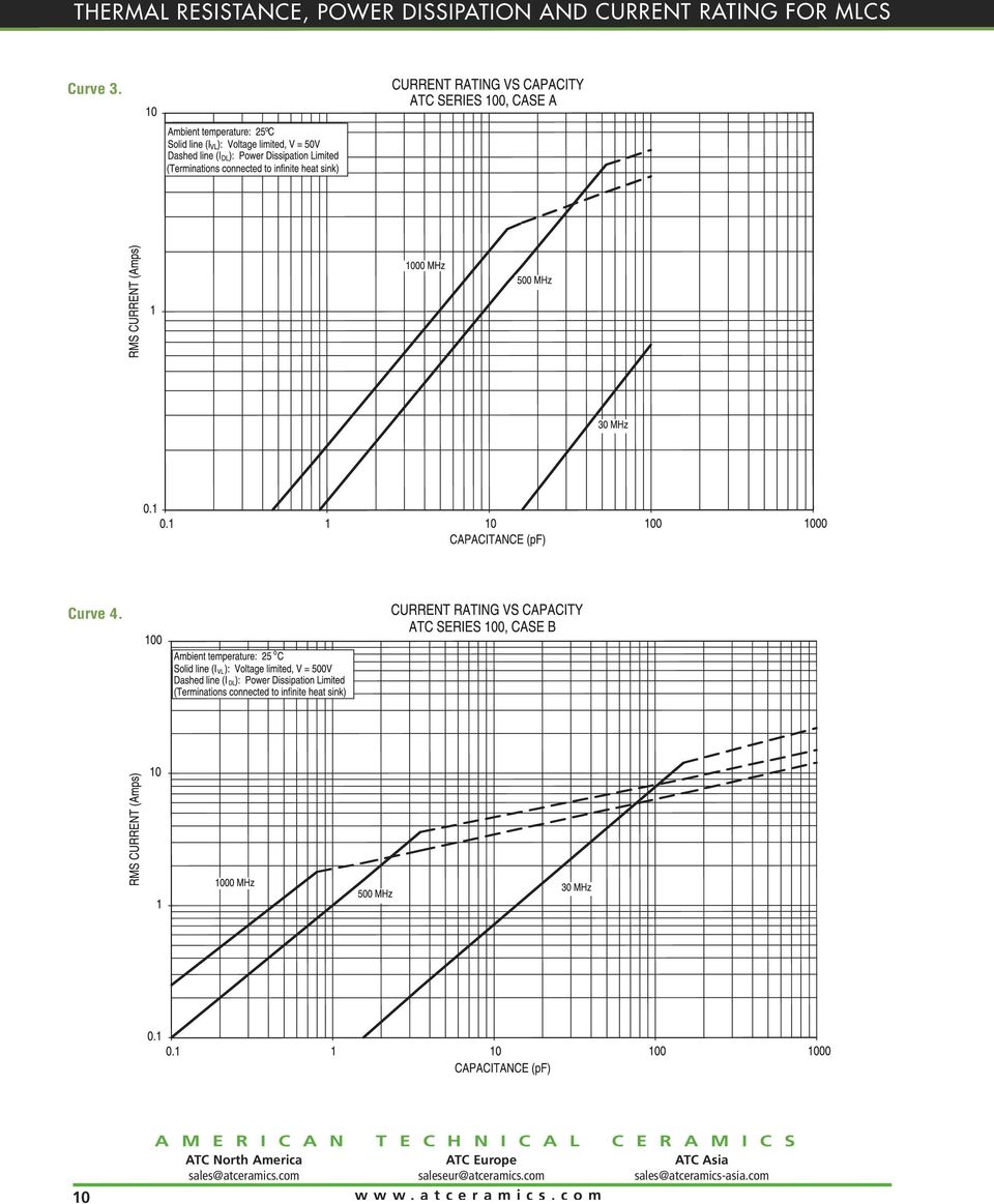
8 Table 2. Infinite Heat 25 C connected to terminations Series 100A 100B Cap value (pf) Θ cap ( C/W) Max Power Diss. (watts) at 25 C allowable Pda either algebraically or graphically.to solve gaphically, use Figure 7 and superimpose: P d = 1 (T 1 - T A ) (9) Θ x This is shown in Figure 10. Starting at T 1 = T A, plot a line whose slope is 1 /Θx; the intersection of the two lines gives the allowed power dissipation and the actual termination temperature for this thermal circuit. The internal temperature (T in ) is 125 C. CURRENT RATINGS Knowing the allowed power dissipation (P da ) in the capacitor, for a given external thermal path, and knowing ESR at the frequency of interest, the dissipation limited current can then be calculated: I DL = P da ESR (10) ESR values can be obtained from ATC performance curves on page 12. I DL is valid as long as the maximum rated voltage of the capacitor is not exceeded. The voltage limited current due to the maximum rated voltage is calculated from Equation 11. I VL = E rated = Erated (2πfC) X c (11) A plot of maximum allowable current vs. capacitance from equations (10) and (11) results in a family of curves as shown in Figure 11. From Figure 11, it is clear that when I VL becomes smaller than I DL, I VL becomes the rated current. See current rating Curves 3, 4 and 5 for 100A and 100B capacitors. CONCLUSION Information and methods for arriving at RF current ratings of multilayer monolithic ceramic capacitors have been presented. It has been shown that the general shape of the current rating curves can be established. Expressions for the effect of various capacitor parameters (such as Equivalent Series Resistance, RF Voltage Rating and Thermal Resistance), on the current ratings have been developed. This data was developed theoretically and then verified experimentally. Examples of how to use this information to arrive at current ratings for specific thermal conditions have been included. Figure 10. Figure 11. 8
 is 125 C.")
9 Curve 1. Curve 2. 9
10 Curve 3. Curve 4. 10
11 Curve 5. Curve 6. 11

12 Curve 7. Curve 8. Curve 9. Curve Q VS CAPACITANCE ATC SERIES 100, CASE B MHz Q MHz MHz (Typical) CAPACITANCE (1.0 pf to 51 pf) Sales of ATC products are subject to the terms and conditions contained in American Technical Ceramics Corp. Terms and Conditions of Sale (ATC document # Rev. B 12/05). Copies of these terms and conditions will be provided upon request. They may also be viewed on ATC's website at /productfinder/default.asp. Click on the link for Terms and Conditions of Sale. ATC has made every effort to have this information as accurate as possible. However, no responsibility is assumed by ATC for its use, nor for any infringements of rights of third parties which may result from its use. ATC reserves the right to revise the content or modify its product line without prior notice American Technical Ceramics Corp. All Rights Reserved. ATC Rev. D; 9/05 12

P O W E R C A P A C I T O R A S S E M B L I E S
 AMERICAN TECHNICAL CERAMICS P O W E R C A P A C I T O R A S S E M B L I E S ISO 9001 REGISTERED COMPANY Overview About ATC Power Assemblies ATC standard & custom Power Assemblies are fabricated from PARALLEL
Current and Temperature Ratings
 Document 361-1 Current and Temperature Ratings Introduction This application note describes: How to interpret Coilcraft inductor current and temperature ratings Our current ratings measurement method and
ATC 600S Series Ultra-Low ESR, High Q, NPO RF & Microwave Capacitors
 AC 600S Series Ultra-Low ESR, High Q, NPO RF & Microwave Capacitors Features: Lowest ESR in Class Highest Working Voltage in class 250V Standard EIA Size: 0603 Laser Marking (Optional) RoHS Compliant High
DATA SHEET SURFACE-MOUNT CERAMIC MULTILAYER CAPACITORS General Purpose & High Capacitance Class 2, X7R
 DATA SHEET SURFACE-MOUNT CERAMIC MULTILAYER CAPACITORS General Purpose & High Capacitance Class 2, 6.3 V TO 50 V 100 pf to 22 µf RoHS compliant & Halogen Free Product Specification October 13, 11 V.8 Product
Measurement of Capacitance
 Measurement of Capacitance Pre-Lab Questions Page Name: Class: Roster Number: Instructor:. A capacitor is used to store. 2. What is the SI unit for capacitance? 3. A capacitor basically consists of two
Types MC and MCN Multilayer RF Capacitors
 High-Frequency, High-Power, High-Voltage Chips with Nonmagnetic Option Rugged flexibility and compatibility with FR4 boards make Type MC and MCN capacitors ideal for use where other multilayer caps aren
DATA SHEET THICK FILM CHIP RESISTORS Introduction
 DATA SHEET THICK FILM CHIP RESISTORS Introduction Product Specification Product specification 2 Chip Resistor Surface Mount Data in data sheets is presented - whenever possible -according to a 'format',
Module 1 : Conduction. Lecture 5 : 1D conduction example problems. 2D conduction
 Module 1 : Conduction Lecture 5 : 1D conduction example problems. 2D conduction Objectives In this class: An example of optimization for insulation thickness is solved. The 1D conduction is considered
ATC 800 B Series NPO Ceramic, High RF Power Ultra-Low ESR Multilayer Capacitors
 800 Series NPO Ceramic, High RF Power Ultra-ow ESR Multilayer Capacitors Case Size (" x ") Rugged, reliable NPO dielectric Case optimized for highest self resonant frequency s 800 Series offers superb
Low Voltage, Resistor Programmable Thermostatic Switch AD22105
 a Low Voltage, Resistor Programmable Thermostatic Switch AD22105 FEATURES User-Programmable Temperature Setpoint 2.0 C Setpoint Accuracy 4.0 C Preset Hysteresis Wide Supply Range (+2.7 V dc to +7.0 V dc)
MADP-000504-10720T. Non Magnetic MELF PIN Diode
 MADP-54-172T Features High Power Handling Low Loss / Low Distortion Leadless Low Inductance MELF Package Non-Magnetic Surface Mountable RoHS Compliant MSL 1 Package Style 172 Dot Denotes Cathode Description
WW12X, WW08X, WW06X, WW04X ±1%, ±5% Thick Film Low ohm chip resistors
 WW12X, WW08X, WW06X, WW04X ±1%, ±5% Thick Film Low ohm chip resistors Size 1206, 0805, 0603, 0402 *Contents in this sheet are subject to change without prior notice. Page 1 of 8 ASC_WWxxX_V12 Nov.- 2011
Surface Mount Multilayer Ceramic Chip Capacitor Solutions for High Voltage Applications
 Surface Mount Multilayer Ceramic Chip Capacitor Solutions for High Voltage Applications ELECTRICAL SPECIFICATIONS X7R GENERAL SPECIFICATION Note Electrical characteristics at +25 C unless otherwise specified
DISCRETE SEMICONDUCTORS DATA SHEET. BLF244 VHF power MOS transistor
 DISCRETE SEMICONDUCTORS DATA SHEET September 1992 FEATURES High power gain Low noise figure Easy power control Good thermal stability Withstands full load mismatch Gold metallization ensures excellent
AC and Pulse Film Foil Capacitors KP Radial Potted Type
 AC and Pulse Film Foil Capacitors KP Radial Potted Type 0.5 L max. W max. Marking H max. FEATURES 5 mm lead pitch, supplied loose in box taped in ammopack or reel Material categorization: for definitions
DC Film Capacitors MKT Radial Potted Type
 DC Film Capacitors MKT Radial Potted Type MKT80 FEATURES AEC-Q00 qualified (rev. D) for PCM. mm (for larger available components on request) High temperature capabilities, up to 0 C Capacitance up to 60
ICS514 LOCO PLL CLOCK GENERATOR. Description. Features. Block Diagram DATASHEET
 DATASHEET ICS514 Description The ICS514 LOCO TM is the most cost effective way to generate a high-quality, high-frequency clock output from a 14.31818 MHz crystal or clock input. The name LOCO stands for
Axial and Radial Leaded Multilayer Ceramic Capacitors for Automotive Applications Class 1 and Class 2, 50 V DC, 100 V DC and 200 V DC
 Axial and Radial Leaded Multilayer Ceramic Capacitors for Automotive Applications Class 1 and Class 2, 5 V DC, 1 V DC and 2 V DC DESIGNING For more than 2 years Vitramon has supported the automotive industry
Avoiding AC Capacitor Failures in Large UPS Systems
 Avoiding AC Capacitor Failures in Large UPS Systems White Paper #60 Revision 0 Executive Summary Most AC power capacitor failures experienced in large UPS systems are avoidable. Capacitor failures can
SECTION 13. Multipliers. Outline of Multiplier Design Process:
 SECTION 13 Multipliers VMI manufactures many high voltage multipliers, most of which are custom designed for specific requirements. The following information provides general information and basic guidance
ELECTRIC FIELD LINES AND EQUIPOTENTIAL SURFACES
 ELECTRIC FIELD LINES AND EQUIPOTENTIAL SURFACES The purpose of this lab session is to experimentally investigate the relation between electric field lines of force and equipotential surfaces in two dimensions.
Surface Mount Multilayer Ceramic Chip Capacitors for Automotive Applications
 Surface Mount Multilayer Ceramic Chip Capacitors for Automotive Applications FEATURES AEC-Q200 qualified with PPAP available Available in 0402 to 1812 body size Three dielectric materials AgPd termination
DC Film Capacitors MKT Radial Potted Type
 DC Film Capacitors MKT Radial Potted Type FEATURES 15 mm to 27.5 mm lead pitch. Supplied loose in box and taped on reel Material categorization: for definitions of compliance please see www.vishay.com/doc?99912
BIASING OF CONSTANT CURRENT MMIC AMPLIFIERS (e.g., ERA SERIES) (AN-60-010)
 (AN-60-010)") BIASING OF CONSTANT CURRENT MMIC AMPLIFIERS (e.g., ERA SERIES) (AN-60-010) Introduction The Mini-Circuits family of microwave monolithic integrated circuit (MMIC) Darlington amplifiers offers the RF designer
BIASING OF CONSTANT CURRENT MMIC AMPLIFIERS (e.g., ERA SERIES) (AN-60-010) Introduction The Mini-Circuits family of microwave monolithic integrated circuit (MMIC) Darlington amplifiers offers the RF designer
High Accuracy, Ultralow IQ, 1.5 A, anycap Low Dropout Regulator ADP3339
 Data Sheet High Accuracy, Ultralow IQ,.5 A, anycap Low Dropout Regulator FEATURES FUNCTIONAL BLOCK DIAGRAM High accuracy over line and load: ±.9% at 5 C, ±.5% over temperature Ultralow dropout voltage:
PowerAmp Design. PowerAmp Design PAD135 COMPACT HIGH VOLATGE OP AMP
 PowerAmp Design COMPACT HIGH VOLTAGE OP AMP Rev G KEY FEATURES LOW COST SMALL SIZE 40mm SQUARE HIGH VOLTAGE 200 VOLTS HIGH OUTPUT CURRENT 10A PEAK 40 WATT DISSIPATION CAPABILITY 200V/µS SLEW RATE APPLICATIONS
Introduction to the Smith Chart for the MSA Sam Wetterlin 10/12/09 Z +
 Introduction to the Smith Chart for the MSA Sam Wetterlin 10/12/09 Quick Review of Reflection Coefficient The Smith chart is a method of graphing reflection coefficients and impedance, and is often useful
RLC Resonant Circuits
 C esonant Circuits Andrew McHutchon April 20, 203 Capacitors and Inductors There is a lot of inconsistency when it comes to dealing with reactances of complex components. The format followed in this document
LDS8720. 184 WLED Matrix Driver with Boost Converter FEATURES APPLICATION DESCRIPTION TYPICAL APPLICATION CIRCUIT
 184 WLED Matrix Driver with Boost Converter FEATURES High efficiency boost converter with the input voltage range from 2.7 to 5.5 V No external Schottky Required (Internal synchronous rectifier) 250 mv
Since any real component also has loss due to the resistive component, the average power dissipated is 2 2R
 Quality factor, Q Reactive components such as capacitors and inductors are often described with a figure of merit called Q. While it can be defined in many ways, it s most fundamental description is: Q
Edmund Li. Where is defined as the mutual inductance between and and has the SI units of Henries (H).
.") INDUCTANCE MUTUAL INDUCTANCE If we consider two neighbouring closed loops and with bounding surfaces respectively then a current through will create a magnetic field which will link with as the flux passes
INDUCTANCE MUTUAL INDUCTANCE If we consider two neighbouring closed loops and with bounding surfaces respectively then a current through will create a magnetic field which will link with as the flux passes
LM2704 Micropower Step-up DC/DC Converter with 550mA Peak Current Limit
 Micropower Step-up DC/DC Converter with 550mA Peak Current Limit General Description The LM2704 is a micropower step-up DC/DC in a small 5-lead SOT-23 package. A current limited, fixed off-time control
Application Note, Rev.1.0, September 2008 TLE8366. Application Information. Automotive Power
 Application Note, Rev.1.0, September 2008 TLE8366 Automotive Power Table of Contents 1 Abstract...3 2 Introduction...3 3 Dimensioning the Output and Input Filter...4 3.1 Theory...4 3.2 Output Filter Capacitor(s)
Electromagnetism Laws and Equations
 Electromagnetism Laws and Equations Andrew McHutchon Michaelmas 203 Contents Electrostatics. Electric E- and D-fields............................................. Electrostatic Force............................................2
CLA Series: Silicon Limiter Diode Bondable Chips
 DATA SHEET CLA Series: Silicon Limiter Diode Bondable Chips Applications LNA receiver protection Commercial and defense radar Features Established Skyworks limiter diode process High-power, mid-range,
SC Series: MIS Chip Capacitors
 DATA SHEET SC Series: MIS Chip Capacitors Applications Systems requiring DC blocking or RF bypassing Fixed capacitance tuning element in filters, oscillators, and matching networks Features Readily available
AS2815. 1.5A Low Dropout Voltage Regulator Adjustable & Fixed Output, Fast Response
 1.5A Low Dropout oltage Regulator Adjustable & Fixed Output, Fast Response FEATURES Adjustable Output Down To 1.2 Fixed Output oltages 1.5, 2.5, 3.3, 5.0 Output Current of 1.5A Low Dropout oltage 1.1 Typ.
An equivalent circuit of a loop antenna.
 3.2.1. Circuit Modeling: Loop Impedance A loop antenna can be represented by a lumped circuit when its dimension is small with respect to a wavelength. In this representation, the circuit parameters (generally
LM3940 1A Low Dropout Regulator for 5V to 3.3V Conversion
 1A Low Dropout Regulator for 5V to 3.3V Conversion General Description The LM3940 is a 1A low dropout regulator designed to provide 3.3V from a 5V supply. The LM3940 is ideally suited for systems which
Using NTC Temperature Sensors Integrated into Power Modules
 Using NTC Temperature Sensors Integrated into Power Modules Pierre-Laurent Doumergue R&D Engineer Advanced Power Technology Europe Chemin de Magret 33700 Mérignac, France Introduction Most APTE (Advanced
Measurement of Inductor Q with the MSA Sam Wetterlin 3/31/11. Equation 1 Determining Resonant Q from Inductor Q and Capacitor Q
 Measurement of Inductor with the MSA Sam Wetterlin 3/31/11 The of an inductor, which is its reactance divided by its internal series resistance, is used as an indication of how well it will perform at
CA723, CA723C. Voltage Regulators Adjustable from 2V to 37V at Output Currents Up to 150mA without External Pass Transistors. Features.
 CA73, CA73C Data Sheet April 1999 File Number 788. Voltage Regulators Adjustable from V to 37V at Output Currents Up to 1mA without External Pass Transistors The CA73 and CA73C are silicon monolithic integrated
www.jameco.com 1-800-831-4242
 Distributed by: www.jameco.com 1-800-831-4242 The content and copyrights of the attached material are the property of its owner. LF411 Low Offset, Low Drift JFET Input Operational Amplifier General Description
Everline Module Application Note: Round LED Module Thermal Management
 Everline Module Application Note: Round LED Module Thermal Management PURPOSE: Use of proper thermal management is a critical element of Light Emitting Diode (LED) system design. The LED temperature directly
EDEXCEL NATIONAL CERTIFICATE/DIPLOMA UNIT 5 - ELECTRICAL AND ELECTRONIC PRINCIPLES NQF LEVEL 3 OUTCOME 4 - ALTERNATING CURRENT
 EDEXCEL NATIONAL CERTIFICATE/DIPLOMA UNIT 5 - ELECTRICAL AND ELECTRONIC PRINCIPLES NQF LEVEL 3 OUTCOME 4 - ALTERNATING CURRENT 4 Understand single-phase alternating current (ac) theory Single phase AC
Digital Energy ITI. Instrument Transformer Basic Technical Information and Application
 g Digital Energy ITI Instrument Transformer Basic Technical Information and Application Table of Contents DEFINITIONS AND FUNCTIONS CONSTRUCTION FEATURES MAGNETIC CIRCUITS RATING AND RATIO CURRENT TRANSFORMER
Polymer Termination. Mechanical Cracking 2. The reason for polymer termination. What is Polymer Termination? 3
 Polymer Termination An alternative termination material specifically designed to absorb greater levels of mechanical stress thereby reducing capacitor failures associated with mechanical cracking Mechanical
High Accuracy, Ultralow IQ, 1 A, anycap Low Dropout Regulator ADP3338
 High Accuracy, Ultralow IQ, 1 A, anycap Low Dropout Regulator ADP3338 FEATURES High accuracy over line and load: ±.8% @ 25 C, ±1.4% over temperature Ultralow dropout voltage: 19 mv (typ) @ 1 A Requires
Features. Symbol JEDEC TO-220AB
 Data Sheet June 1999 File Number 2253.2 3A, 5V,.4 Ohm, N-Channel Power MOSFET This is an N-Channel enhancement mode silicon gate power field effect transistor designed for applications such as switching
EXTENDING THE LIFE OF POWER FACTOR CAPACITORS
 by John Houdek, President, Allied Industrial Marketing, Inc., and Cesar Chavez, Engineering Manager, ARTECHE / Inelap Abstract: The addition of power factor improvement capacitors to individual motors
STLM20. Ultra-low current 2.4 V precision analog temperature sensor. Features. Applications
 Ultra-low current 2.4 V precision analog temperature sensor Features Precision analog voltage output temperature sensor ±1.5 C maximum temperature accuracy at 25 C (±0.5 C typical) Ultra-low quiescent
Basic Electronics Prof. Dr. Chitralekha Mahanta Department of Electronics and Communication Engineering Indian Institute of Technology, Guwahati
 Basic Electronics Prof. Dr. Chitralekha Mahanta Department of Electronics and Communication Engineering Indian Institute of Technology, Guwahati Module: 2 Bipolar Junction Transistors Lecture-2 Transistor
2N6056. NPN Darlington Silicon Power Transistor DARLINGTON 8 AMPERE SILICON POWER TRANSISTOR 80 VOLTS, 100 WATTS
 NPN Darlington Silicon Power Transistor The NPN Darlington silicon power transistor is designed for general purpose amplifier and low frequency switching applications. High DC Current Gain h FE = 3000
Sophomore Physics Laboratory (PH005/105)
") CALIFORNIA INSTITUTE OF TECHNOLOGY PHYSICS MATHEMATICS AND ASTRONOMY DIVISION Sophomore Physics Laboratory (PH5/15) Analog Electronics Active Filters Copyright c Virgínio de Oliveira Sannibale, 23 (Revision
CALIFORNIA INSTITUTE OF TECHNOLOGY PHYSICS MATHEMATICS AND ASTRONOMY DIVISION Sophomore Physics Laboratory (PH5/15) Analog Electronics Active Filters Copyright c Virgínio de Oliveira Sannibale, 23 (Revision
28 Volt Input - 40 Watt
 Features Powers 28 volt dc-dc converters during power dropout Input voltage 12 to 40 volts Operating temperature -55 to +125 C Reduces hold-up capacitance by 80% Inhibit function Synchronization function
Capacitor Self-Resonance
 Capacitor Self-Resonance By: Dr. Mike Blewett University of Surrey United Kingdom Objective This Experiment will demonstrate some of the limitations of capacitors when used in Radio Frequency circuits.
Metallized Polypropylene Film Capacitors DC-Link Capacitor
 Metallized Polypropylene Film Capacitors DC-Link Capacitor FEATURES Slim line, low building height Very long useful life time: Up to 100 000 h at U NDC and 70 C High ripple current capability, low ESR,
Understanding Power Impedance Supply for Optimum Decoupling
 Introduction Noise in power supplies is not only caused by the power supply itself, but also the load s interaction with the power supply (i.e. dynamic loads, switching, etc.). To lower load induced noise,
Application Guide Film Capacitors
 Capacitance Change vs. Temperature Insulation Resistance vs. Temperature Polyester Typical Characteristics at 1 khz % Capacitance Change % Capacitance Change Polypropylene Typical Characteristics at 1
NUD4011. Low Current LED Driver
 NUD0 Low LED Driver This device is designed to replace discrete solutions for driving LEDs in AC/DC high voltage applications (up to 00 V). An external resistor allows the circuit designer to set the drive
SELECTION GUIDE. Nominal Input
 www.murata-ps.com NKE Series FEATURES RoHS Compliant Sub-Miniature SIP & DIP Styles 3kVDC Isolation UL Recognised Wide Temperature performance at full 1 Watt load, 40 C to 85 C Increased Power Density
LDO03C/LDO06C/LDO10C
 NEW LDO03C/LDO06C/LDO10C A p p l i c a t i o n N o t e 1 8 6 1. Introduction 2 2. Models Features 2 3. General Description Electrical Description 2 Physical Construction 2 4. Features and Functions Wide
Series AMLDL-Z Up to 1000mA LED Driver
 FEATURES: Click on Series name for product info on aimtec.com Series Up to ma LED Driver Models Single output Model Input Voltage (V) Step Down DC/DC LED driver Operating Temperature range 4ºC to 85ºC
Series and Parallel Circuits
 Series and Parallel Circuits Components in a circuit can be connected in series or parallel. A series arrangement of components is where they are inline with each other, i.e. connected end-to-end. A parallel
Toroids. Toroids. Design Considerations
 Ferrite toroids provide an often convenient and very effective shape for many wide band, pulse and power transformers and inductors. The continuous magnetic path yields the highest effective permeability
HA-5104/883. Low Noise, High Performance, Quad Operational Amplifier. Features. Description. Applications. Ordering Information. Pinout.
 HA5104/883 April 2002 Features This Circuit is Processed in Accordance to MILSTD 883 and is Fully Conformant Under the Provisions of Paragraph 1.2.1. Low Input Noise Voltage Density at 1kHz. 6nV/ Hz (Max)
Advanced Monolithic Systems
 Advanced Monolithic Systems FEATURES Three Terminal Adjustable or Fixed oltages* 1.5, 1.8, 2.5, 2.85, 3.3 and 5. Output Current of 1A Operates Down to 1 Dropout Line Regulation:.2% Max. Load Regulation:.4%
AP1509. 150KHz, 2A PWM BUCK DC/DC CONVERTER. Description. Pin Assignments V IN. Applications. Features. (Top View) GND GND. Output AP1509 GND GND
 GND GND. Output AP1509 GND GND") Description Pin Assignments The series are monolithic IC designed for a stepdown DC/DC converter, and own the ability of driving a 2A load without additional transistor. It saves board space. The external
Description Pin Assignments The series are monolithic IC designed for a stepdown DC/DC converter, and own the ability of driving a 2A load without additional transistor. It saves board space. The external
HIGH VOLTAGE ELECTROSTATIC PENDULUM
 HIGH VOLTAGE ELECTROSTATIC PENDULUM Raju Baddi National Center for Radio Astrophysics, TIFR, Ganeshkhind P.O Bag 3, Pune University Campus, PUNE 411007, Maharashtra, INDIA; [email protected] ABSTRACT
3EZ6.2D5 Series. 3 Watt DO-41 Surmetic 30 Zener Voltage Regulators
 EZ6.D Series Watt DO- Surmetic Zener Voltage Regulators This is a complete series of Watt Zener diodes with limits and excellent operating characteristics that reflect the superior capabilities of silicon-oxide
Application Note AN:005. FPA Printed Circuit Board Layout Guidelines. Introduction Contents. The Importance of Board Layout
 FPA Printed Circuit Board Layout Guidelines By Paul Yeaman Principal Product Line Engineer V I Chip Strategic Accounts Introduction Contents Page Introduction 1 The Importance of 1 Board Layout Low DC
CMOS Switched-Capacitor Voltage Converters ADM660/ADM8660
 CMOS Switched-Capacitor Voltage Converters ADM66/ADM866 FEATURES ADM66: Inverts or Doubles Input Supply Voltage ADM866: Inverts Input Supply Voltage ma Output Current Shutdown Function (ADM866) 2.2 F or
THERMAL DESIGN AND TEST REQUIREMENTS FOR OUTSIDE PLANT CABLE TELECOMMUNICATIONS EQUIPMENT Al Marshall, P.E. Philips Broadband Networks
 THERMAL DESIGN AND TEST REQUIREMENTS FOR OUTSIDE PLANT CABLE TELECOMMUNICATIONS EQUIPMENT Al Marshall, P.E. Philips Broadband Networks Abstract Shrinking thermal margins, driven by sophisticated but thermally
Eatman Associates 2014 Rockwall TX 800-388-4036 rev. October 1, 2014. Striplines and Microstrips (PCB Transmission Lines)
") Eatman Associates 2014 Rockwall TX 800-388-4036 rev. October 1, 2014 Striplines and Microstrips (PCB Transmission Lines) Disclaimer: This presentation is merely a compilation of information from public
Eatman Associates 2014 Rockwall TX 800-388-4036 rev. October 1, 2014 Striplines and Microstrips (PCB Transmission Lines) Disclaimer: This presentation is merely a compilation of information from public
Thermal Management of Electronic Devices used in Automotive Safety A DoE approach
 Thermal Management of Electronic Devices used in Automotive Safety A DoE approach Vinod Kumar, Vinay Somashekhar and Srivathsa Jagalur Autoliv India Private Limited, Bangalore, India Abstract: Electronic
1 Form A Solid State Relay
 Form A Solid State Relay VOAT, VOAABTR FEATURES 9 S S DC S' 3 S' High speed SSR - t on /t off < 8 μs Maximum R ON. Isolation test voltage 3 V RMS Load voltage V Load current A DC configuration DIP- package
Rail-to-Rail, High Output Current Amplifier AD8397
 Rail-to-Rail, High Output Current Amplifier AD8397 FEATURES Dual operational amplifier Voltage feedback Wide supply range from 3 V to 24 V Rail-to-rail output Output swing to within.5 V of supply rails
PDS5100H. Product Summary. Features and Benefits. Mechanical Data. Description and Applications. Ordering Information (Note 5) Marking Information
 Marking Information") Green 5A HIGH VOLTAGE SCHOTTKY BARRIER RECTIFIER POWERDI 5 Product Summary I F V R V F MAX (V) I R MAX (ma) (V) (A) @ +25 C @ +25 C 1 5..71.35 Description and Applications This Schottky Barrier Rectifier
Green 5A HIGH VOLTAGE SCHOTTKY BARRIER RECTIFIER POWERDI 5 Product Summary I F V R V F MAX (V) I R MAX (ma) (V) (A) @ +25 C @ +25 C 1 5..71.35 Description and Applications This Schottky Barrier Rectifier
Mylar polyester film. Electrical Properties. Product Information. Dielectric Strength. Electrode Size. Film Thickness
 Product Information Mylar polyester film Electrical Properties Mylar offers unique design capabilities to the electrical industry due to the excellent balance of its electrical properties with its chemical,
Experiment #5, Series and Parallel Circuits, Kirchhoff s Laws
 Physics 182 Summer 2013 Experiment #5 1 Experiment #5, Series and Parallel Circuits, Kirchhoff s Laws 1 Purpose Our purpose is to explore and validate Kirchhoff s laws as a way to better understanding
4 SENSORS. Example. A force of 1 N is exerted on a PZT5A disc of diameter 10 mm and thickness 1 mm. The resulting mechanical stress is:
 4 SENSORS The modern technical world demands the availability of sensors to measure and convert a variety of physical quantities into electrical signals. These signals can then be fed into data processing
Experiment #3, Ohm s Law
 Experiment #3, Ohm s Law 1 Purpose Physics 182 - Summer 2013 - Experiment #3 1 To investigate the -oltage, -, characteristics of a carbon resistor at room temperature and at liquid nitrogen temperature,
AP1506. 150KHz, 3A PWM BUCK DC/DC CONVERTER. Pin Assignments. Description. Features. Applications. ( Top View ) 5 SD 4 FB 3 Gnd 2 Output 1 V IN
 5 SD 4 FB 3 Gnd 2 Output 1 V IN") Description Pin Assignments The series are monolithic IC designed for a stepdown DC/DC converter, and own the ability of driving a 3A load without external transistor. Due to reducing the number of external
Description Pin Assignments The series are monolithic IC designed for a stepdown DC/DC converter, and own the ability of driving a 3A load without external transistor. Due to reducing the number of external
Connectivity in a Wireless World. Cables Connectors 2014. A Special Supplement to
 Connectivity in a Wireless World Cables Connectors 204 A Special Supplement to Signal Launch Methods for RF/Microwave PCBs John Coonrod Rogers Corp., Chandler, AZ COAX CABLE MICROSTRIP TRANSMISSION LINE
Impedance Matching. Using transformers Using matching networks
 Impedance Matching The plasma industry uses process power over a wide range of frequencies: from DC to several gigahertz. A variety of methods are used to couple the process power into the plasma load,
ICS650-01 SYSTEM PERIPHERAL CLOCK SOURCE. Description. Features. Block Diagram DATASHEET
 DATASHEET ICS650-01 Description The ICS650-01 is a low-cost, low-jitter, high-performance clock synthesizer for system peripheral applications. Using analog/digital Phase-Locked Loop (PLL) techniques,
Part Marking Instructions Chip Resistors
 Chip Resistors Part Marking Instructions Part Marking Instructions Chip Resistors 1% Marking The nominal resistance is marked on the surface of the overcoating with the use of 4 digit markings. 0201 and
BSP52T1 MEDIUM POWER NPN SILICON SURFACE MOUNT DARLINGTON TRANSISTOR
 Preferred Device This NPN small signal darlington transistor is designed for use in switching applications, such as print hammer, relay, solenoid and lamp drivers. The device is housed in the SOT-223 package,
LM118/LM218/LM318 Operational Amplifiers
 LM118/LM218/LM318 Operational Amplifiers General Description The LM118 series are precision high speed operational amplifiers designed for applications requiring wide bandwidth and high slew rate. They
VJ 6040 Mobile Digital TV UHF Antenna Evaluation Board
 VISHAY VITRAMON Multilayer Chip Capacitors Application Note GENERAL is a multilayer ceramic chip antenna designed for receiving mobile digital TV transmissions in the UHF band. The target application for
Pulse Withstanding Thick Film Chip Resistor-SMDP Series. official distributor of
 Product: Pulse Withstanding Thick Film Chip Resistor-SMDP Series Size: /// official distributor of Pulse Withstanding Thick Film Chip Resistor-SMDP Series 1. Scope -This specification applies to ~ sizes
LUXEON LEDs. Circuit Design and Layout Practices to Minimize Electrical Stress. Introduction. Scope LED PORTFOLIO
 LED PORTFOLIO LUXEON LEDs Circuit Design and Layout Practices to Minimize Electrical Stress Introduction LED circuits operating in the real world can be subjected to various abnormal electrical overstress
Welcome to this presentation on LED System Design, part of OSRAM Opto Semiconductors LED 101 series.
 Welcome to this presentation on LED System Design, part of OSRAM Opto Semiconductors LED 101 series. 1 To discuss the design challenges of LED systems we look at the individual system components. A basic
unit : mm With heat sink (see Pd Ta characteristics)
") Ordering number: EN1321E Monolithic Linear IC LA4261 3.5 W 2-Channel AF Power Amplifier for Home Stereos and Music Centers Features. Minimum number of external parts required (No input capacitor, bootstrap
Ordering number: EN1321E Monolithic Linear IC LA4261 3.5 W 2-Channel AF Power Amplifier for Home Stereos and Music Centers Features. Minimum number of external parts required (No input capacitor, bootstrap
A Practical Guide to Dielectric Testing
 Chroma Systems Solutions, Inc. A Practical Guide to Dielectric Testing 19032 Series Electrical Safety Analyzer & 19050 Series Hipot Tester AC/DC/IR/SCAN Keywords: Dielectric tests, insulation resistance
Vdc. Vdc. Adc. W W/ C T J, T stg 65 to + 200 C
 2N6284 (NPN); 2N6286, Preferred Device Darlington Complementary Silicon Power Transistors These packages are designed for general purpose amplifier and low frequency switching applications. Features High
LM1084 5A Low Dropout Positive Regulators
 5A Low Dropout Positive Regulators General Description The LM1084 is a series of low dropout voltage positive regulators with a maximum dropout of 1.5 at 5A of load current. It has the same pin-out as
P D 215 1.25 Operating Junction Temperature T J 200 C Storage Temperature Range T stg 65 to +150 C
 SEMICONDUCTOR TECHNICAL DATA Order this document by /D The RF Line The is designed for output stages in band IV and V TV transmitter amplifiers. It incorporates high value emitter ballast resistors, gold
Diode Circuits. Operating in the Reverse Breakdown region. (Zener Diode)
") Diode Circuits Operating in the Reverse Breakdown region. (Zener Diode) In may applications, operation in the reverse breakdown region is highly desirable. The reverse breakdown voltage is relatively insensitive
Diode Circuits Operating in the Reverse Breakdown region. (Zener Diode) In may applications, operation in the reverse breakdown region is highly desirable. The reverse breakdown voltage is relatively insensitive