BACK PRESSURE MONITOR Operator Display with Exhaust Temperature KIT
|
|
|
- Joy Townsend
- 9 years ago
- Views:
Transcription
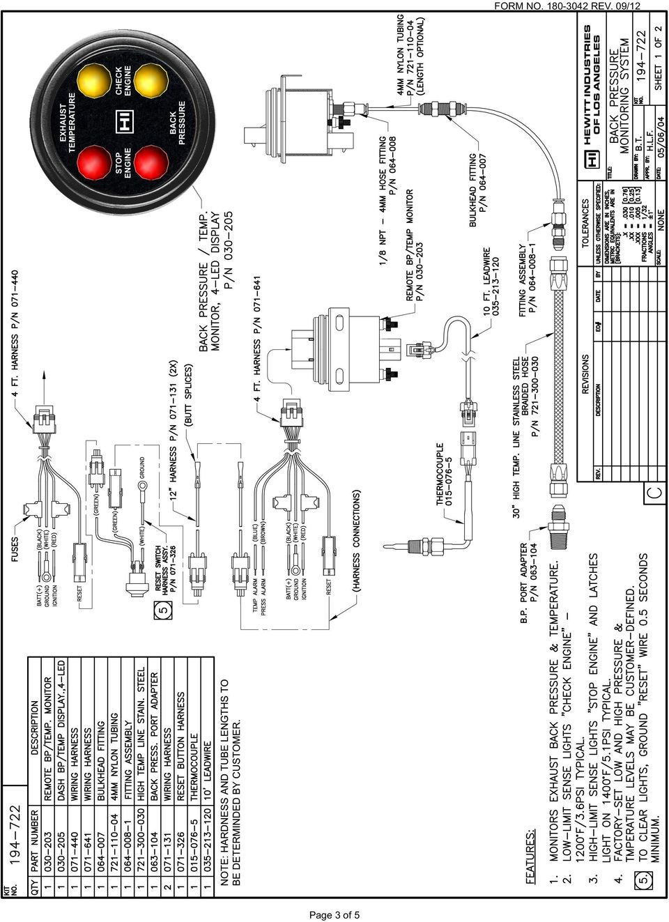
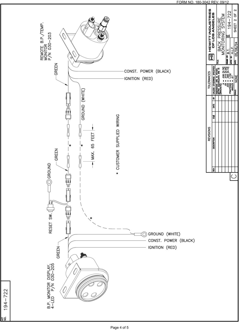
1 HEWITT INDUSTRIES 5492 BOLSA AVE. HUNTINGTON BEACH, CA PH. (714) FAX. (714) WEBSITE: BACK PRESSURE MONITOR Operator Display with Exhaust Temperature KIT Device Operation and Installation Back Pressure Monitor Kit (P/N ) is a microprocessor based controller that monitors exhaust system back pressure and indicates excessive pressure. Two lights indicate the presence of initial high back pressure level (Yellow - Service Engine) and extreme high back pressure level (Red - Stop Engine). Two additional lights indicate excessive exhaust temperature, a Yellow - Service Engine and a Red - stop Engine. The lights remain lit once the pressure levels are reached and will appear after the event indefinitely until reset by maintenance personnel. The P/N Remote Transducer Module employs an internal pressure transducer to measure exhaust pressure. The exhaust pipe is tapped ahead of the particulate filter or catalytic converter. Exhaust passes through a stainless steel hose and then through Tygon tubing to reach the P/N module unit. Exhaust temperature is sensed using a thermocouple. The P/N Remote Transducer module is connected to the P/N Dashboard Display module. The display contains the four (4) alarm LED s. The initial high back pressure level light (Yellow) is typically triggered at a pressure of 3.6 PSI (determined by application, factory and field adjustable for REV 1.4 and up). This light indicates that servicing of the vehicle is required. The pressure level is filtered for fifteen (15) seconds to ignore spikes in pressure that occur in normal engine use. The initial high exhaust temperature (Yellow) is triggered at 1200ºF. This setting is also filed adjustable. When the pressure and temperature falls below the low limit, the Yellow light will continue to be lit. The extreme high back pressure level light (Red) is triggered at a pressure of 5.1 PSI (determined by application, factory and field adjustable for Rev 1.4 and up). This light indicates a potentially damaging pressure level has been reached. The pressure level is filtered for fifteen (15) seconds to ignore spikes in pressure that occur in normal engine use. The extreme high exhaust temperature (Red) is triggered at 1400ºF. Upon detection of high temperature or high pressure level for fifteen (15) seconds, the Display will begin to flash the Red extreme pressure light and will continue to flash as long as pressure remains continuously above the high pressure limit. When the pressure falls below the high limit, the Red light will cease to flash but will remain lit. Resetting the lights for maintenance is accomplished by pressing the reset switch for a minimum of one (1) second. The lights will be extinguished at that time and the unit is ready for normal operation. If the reset switch were held on for five (5) seconds, then the module would enter the self-test mode and flash the lights on the module. A self-test feature is exercised when the ignition is turned on, causing the two lights to flash for approximately three (3) seconds to indicate proper operation of the module. After the self-test concludes the module may leave either or both lights illuminated to indicate a past over-pressure event. The lights can only be reset by maintenance personnel while the ignition is on. If ignition is turned off, the module retains memory of the overpressure event(s) as long as the vehicle battery is connected. Page 1 of 5
 and extreme high back pressure level (Red - Stop Engine).")
2 BACK PRESSURE MONITOR Operator Display with Exhaust Temperature KIT The Remote Sender also provides two (2) open-collector (grounding) outputs suitable to drive external automotive relays (12 volt P/N , 24 volt P/N ) or as inputs to the vehicle ECU. One output will engage and latch on when the high pressure limit is exceeded for thirty (30) seconds continuously. The second output engages and latches on similarly for the high temperature limit. The relay output functions are independent of the display functions. The P/N Remote Transducer module communicates with the Dashboard Display or Dashboard Throttle Control through the Link / Reset wire that connects the two (2) units together. The communication is constant unless the wire is interrupted or grounded. Grounding the Link / Reset wire is accomplished by the reset switch to clear the alarm lights. If the display module detects an open or shorted Link / Reset wire, then the self-test mode is initiated, causing the alarm lights to flash. Detection of an open wire occurs in approximately one (1) second. Detection of a short occurs in approximately five (5) seconds. Operation Summary 1. Ignition on self-test feature causes both Red and Yellow lights to flash for three (3) seconds. 2. As long as over-pressure conditions are not sensed, the lights go off to indicate normal engine operation. 3. When the lower pressure level is reached due to initial excess back pressure, the Yellow light will be illuminated to signal engine service is required. 4. When the upper pressure level is reached due to extreme excess back pressure, the Red light will begin to flash and if Throttle Control is employed, the throttle level will begin to derate slowly (approximately 1% - 3% per second). 5. As long as extreme pressure condition remains, the Red light will continue to flash. 6. The Yellow light will always be lit whenever the Red light is flashing or lit because both over-pressure limits will have been reached. 7. Over-pressure spikes during normal engine operation (i.e. initial burst in RPM upon acceleration) are ignored for fifteen (15) seconds. 8. The Red and Yellow lights remain lit after the over-pressure condition is reached and as long as ignition is on until reset by maintenance personnel. 9. When ignition is turned off, the lights will go off. 10. When ignition is turned on again, the lights will flash for self-test and then will display the previous over-pressure condition if it occurred. Page 2 of 5
 units together.")
3 Page 3 of 5
4 Page 4 of 5
5 Example: Low or High Over-Pressure Condition OVER-PRESSURE SENSED 15 SECONDS DELAY ALARM LIGHT FLASHING ALARM LIGHT LIT TROUBLESHOOTING CHART SYMPTOM POSSIBLE CAUSE CORRECTIVE ACTION After self-test, YELLOW light stays lit Normal operation, indicates that Service exhaust system and are permanently cleared by RESET switch lower over-pressure limit was exceeded After self-test, RED and YELLOW lights stay lit and are permanently cleared by RESET switch Ignition off, RED or YELLOW light illuminated Turn on ignition, RED and/or YELLOW lights do not flash for 3 seconds Turn on ignition, after self-test (3 seconds), RED light stays on but YELLOW light is off After self-test, RED or YELLOW lights stay on, but are not cleared by RESET switch when pressed After self-test, RED light stays on, is cleared by RESET switch, but then goes on again without engine running After self-test, YELLOW light stays on, is cleared by RESET switch, but then goes on again without engine running Ignition on, neither RED nor YELLOW lights lit, but engine RPM is extremely limited and not increased when throttle pedal is pressed Ignition on, neither RED nor YELLOW lights lit, engine RPM is limited, but increases when throttle pedal is pressed Ignition on, after self-test flashing for 3 seconds, both lights continue to flash indefinitely Ignition on, after self-test flashing is completed, and additional delay of five seconds with lights out, then both lights begin to flash for three seconds. Cycle repeats every five seconds. Normal operation, indicates that low and high over-pressure limits were exceeded Defective high-pressure switch Open high-pressure switch Open low-pressure switch Defective throttle pedal cable or defective module Reset/link wire is open Reset/link wire is shorted to ground Service exhaust system Disconnect module from throttle pedal, bypass module by directly connecting throttle pedal wire. If symptoms persist then module is not source of problem. Verify connection of LINK/RESET wire (green) between the modules. Verify power and ground at the P/N Remote Transducer module. Verify ignition signal at P/N module. Verify connection of LINK/RESET wire (green) between the modules. Disconnect from module and verify wire is not shorted to ground with ohmmeter. Verify reset switch is not shorted. Page 5 of 5
, RED light stays on but YELLOW light is off After self-test, RED or YELLOW lights stay on, but are not cleared by RESET switch when pressed After self-test, RED light stays on,")
PUSH BUTTON START INSTALLATION MANUAL
 PUSH BUTTON START INSTALLATION MANUAL ALTHOUGH THIS PRODUCT HAS BEEN THOROUGHLY TESTED KPIERSON TECHNOLOGIES ASSUMES NO RESPONSIBILITY FOR ANY DAMAGE THAT MAY RESULT BY THE INSTALLATION OF THIS PRODUCT.
ILISC515-A Shift Interlock (Manual Lift Door) 2015 Ford Transit, 3.7L and 3.5L
 2015 Ford Transit, 3.7L and 3.5L") An ISO 9001:2008 Registered Company ILISC515-A Shift Interlock (Manual Lift Door) 2015 Ford Transit, 3.7L and 3.5L Introduction The ILISC515-A is a microprocessor driven system for controlling wheelchair
An ISO 9001:2008 Registered Company ILISC515-A Shift Interlock (Manual Lift Door) 2015 Ford Transit, 3.7L and 3.5L Introduction The ILISC515-A is a microprocessor driven system for controlling wheelchair
INSTRUMENT PANEL. 1995 Volvo 850 DESCRIPTION & OPERATION. 1995-96 ACCESSORIES & EQUIPMENT Volvo Instrument Panels
 INSTRUMENT PANEL 1995 Volvo 850 1995-96 ACCESSORIES & EQUIPMENT Volvo Instrument Panels 850 WARNING: When working around steering column and before performing repairs, disconnect and shield battery ground
Troubleshooting Guide, Freedom and Fleet Power Inverter/Chargers
 Technical Note Freedom/Fleet Power 512-0084-01-01 Rev 1 Troubleshooting Guide, Freedom and Fleet Power Inverter/Chargers Overview This document is a guide for troubleshooting inverters, battery chargers,
BLOCK OCCUPANCY DETECTOR WITH SEMAPHORE OPERATION BOD1/DAP4-BR
 BLOCK OCCUPANCY DETECTOR WITH SEMAPHORE OPERATION BOD1/DAP4-BR This Block Occupancy Detector recognises the current drawn by moving trains within a block, and can operate a number of built-in programs
Electronic Power Control
 Service. Self-Study Programme 210 Electronic Power Control Design and Function With the Electronic Power Control system, the throttle valve is actuated only by an electric motor. This eliminates the need
VEHICLE SECURITY SYSTEM G25/G20
 VEHICLE SECURITY SYSTEM G25/G20 Limited Lifetime Warranty This vehicle security system is warranted to the original purchaser, to be free from defects in material and workmanship. The manufacturer will
OWNER'S MANUAL Installation, Operation, and Maintenance Information
 OWNER'S MANUAL Installation, Operation, and Maintenance Information Back Pressure Monitor (BPM) for Diesel Particulate Filter Mufflers Manual No. P480922 Rev 1 This manual is property of the owner. Leave
Thermo Top - Troubleshooting Tree
 Thermo Top - Troubleshooting Tree 07-15-2002 CAUTION Troubleshooting requires comprehensive knowledge about the structure and theory of operation of the Thermo Top heater. Troubleshooting and repairs may
SELECTION, APPLICATION AND MAINTENANCE
 DIESEL PROTECTION SYSTEMS Automatic Diesel Engine Shut Down System for Safe Area Applications SELECTION, APPLICATION AND MAINTENANCE Series 300 Series 310 SYSTEM DESCRIPTION Suitable for attended engine
ANTI-THEFT SYSTEM. 1995 Volvo 850 DESCRIPTION & OPERATION BASIC ALARM. 1995-96 ACCESSORIES & EQUIPMENT Volvo Anti-Theft Systems
 ANTI-THEFT SYSTEM 1995 Volvo 850 1995-96 ACCESSORIES & EQUIPMENT Volvo Anti-Theft Systems 850 DESCRIPTION & OPERATION WARNING: Deactivate air bag system before performing any service operation. For 1995
WARRANTY AND DISCLAIMER
 2036 Fillmore Street Davenport, Ia. 52804 563-324-1046 www.racedigitaldelay.com MEGA 350/450 WARRANTY AND DISCLAIMER DIGITAL DELAY INC. WARRANTS THE PRODUCTS IT MANUFACTURES AGAINST DEFECTS IN MATERIALS
Mini Effect Gizmo. User s Manual. RJM Music Technology, Inc.
 Mini Effect Gizmo User s Manual RJM Music Technology, Inc. Mini Effect Gizmo User s Manual Version 1.3 September 26, 2013 RJM Music Technology, Inc. 2525 Pioneer Ave #1 Vista, CA 92081 E-mail: [email protected]
Meritor WABCO Pneumatic Antilock Braking System (ABS) 42.22
 42.22") (ABS) 2.22 Troubleshooting WARNING Before testing a vehicle equipped with Automatic Traction Control (ATC) on a dynamometer, the ATC system must be disabled. See Subject 160 for instructions. Activation
(ABS) 2.22 Troubleshooting WARNING Before testing a vehicle equipped with Automatic Traction Control (ATC) on a dynamometer, the ATC system must be disabled. See Subject 160 for instructions. Activation
Impact Uni-Vent 750 Portable Ventilator
 Impact Uni-Vent 750 Portable Ventilator Description - Indications- Contraindications- Side Effects- Special Considerations- The Uni-Vent 750 Portable Ventilator is a portable electronically controlled,
Introduction to Electronic Signals
 Introduction to Electronic Signals Oscilloscope An oscilloscope displays voltage changes over time. Use an oscilloscope to view analog and digital signals when required during circuit diagnosis. Fig. 6-01
Impact Uni-Vent 754 Portable Ventilator
 Impact Uni-Vent 754 Portable Ventilator Description - Indications- Contraindications- Side Effects- Special Considerations- The Uni-Vent 754 Portable Ventilator is a portable electronically controlled,
APAds Air Conditioning Protection and Control System. Technical Help Frequently Asked Questions
 APAds Air Conditioning Protection and Control System www.indexsensors.com Technical Help Frequently Asked Questions Subject Areas Covered: A. WHAT APAds DOES / HOW IT WORKS B. READING BLINK CODES C. MISCELLANEOUS
Installation instructions for VW Golf VII & Skoda Octavia III all models 2013 > Signals on CAN: Brake - Clutch - VSS
 EL-PAS -Cruise II Installation instructions for VW Golf VII & Skoda Octavia III all models 2013 > Signals on CAN: Brake - Clutch - VSS e-cruise www.lpdk.com LP Lindgaard Pedersen A/S Page 1 / 5 Before
Automotive Sensor Simulator. Automotive sensor simulator. Operating manual. AutoSim
 Automotive sensor simulator Operating manual AutoSim Contents Introduction.. page 3 Technical specifications.... page 4 Typical application of AutoSim simulator..... page 4 Device appearance... page 5
Signature and ISX CM870 Electronics
 Signature and ISX CM870 Electronics Cummins West Training Center System Description General Information The Signature and ISX CM870 engine control system is an electronically operated fuel control system
INSTALLATION GUIDE OWNER S GUIDE
 INSTALLATION GUIDE OWNER S GUIDE TALKING ALARM MODEL 3001 CONTENTS System Features... 1 Technical Assistance... 1 Wiring Instructions... 2 Installation Instructions... 3 Operating Instructions... 4-5 Technical
Workshop Repair Manual
 Workshop Repair Manual N.T. 2863A All types Basic manual: M.R. 302 - M.R. 307 - M.R. 311 - M.R. 312 M.R. 291 - M.R. 293 77 11 196 407 OCTOBER 1997 Edition Anglaise "The repair methods given by the manufacturer
FA-300 Series. LCD Fire Alarm Control Panel. User Guide. LT-954 Rev. 0.1 February 2013. FA-300 SERIES Fire Alarm Control Panel
 ABC DEF GHI JKL MNO PQR STU YZ WXY FA-300 Series LCD Fire Alarm Control Panel Advanced Life Safety Solutions System Normal 10:36AM WED 2003-10-01 SYSTEM RESET A.C. ON ALARM SUPV TRBL CPU FAIL SIGNAL SILENCE
HPC Radiator Fan Control Module with Sensor PN: 102001
 Revised 25.07.15 www.hpcontrols.ca HPC Radiator Fan Control odule with Sensor PN: 102001 The HPC Radiator Fan Controller provides automatic control over one or more electric radiator fan(s). The module
REC FIM LOCKPICK INSTALLATION OPTIONS
 REC FIM LOCKPICK INSTALLATION OPTIONS TM PLUG INTO RADIO PLUG WHITE CONNECTOR INTO RADIO PLUG AND PLAY RADIO CONNECTORS UNPLUG ORIGINAL RADIO GRAY CONNECTOR THEN PLUG IN HERE AFTERMARKET FRONT CAMERA VIDEO
MODEL 5010 DUAL CHANNEL SMOKE/FIRE DETECTION MODULE
 DESCRIPTION MODEL 5010 DUAL CHANNEL SMOKE/FIRE DETECTION MODULE DESCRIPTION The SST Model 5010 Two Channel Smoke/Fire Detection Module provides two independent detection input channels for the NOVA-5000
Car Alarm Series 2 B 2 Buttons
 Car Alarm Series 2 B 2 Buttons G22 SE (External - Shock Sensor) Version 3 Software 67 Plus www.geniuscaralarm.com 21 CAR ALARM GENIUS Series 2B 2 Buttons - G22 Se (External Shock Sensor) Module controlled
INSTALLATION GUIDE. www.security.soundstream.com FCC ID NOTICE
 AL.1 AUTO SECURITY SYSTEM INSTALLATION GUIDE www.security.soundstream.com FCC ID NOTICE This device complies with Part 15 of the FCC rules. Operation is subject to the following conditions: 1. This device
ODYSSEY. Security System Owner s Manual. Kit No. 08E51-SHJ-100 08E55-SHJ-100. 2004 American Honda Motor Co., Inc. - All Rights Reserved.
 Kit No. 08E5-SHJ-00 08E55-SHJ-00 Security System Owner s Manual ODYSSEY 004 American Honda Motor Co., Inc. - All Rights Reserved. Contents Introduction... 3 Emergency Disarming During the Panic Alarm Activation...
FAN-PWM-V3. Instructions
 FAN-PWM-V3 Instructions HOLDER AMP BOOKLET YELLOW RING CONNECTORS (2) INSTRUCTION INSTRUCTION BOOKLETBOOKLET ITEMS INCLUDED IN KIT INSTRUCTION ITEMS INCLUDED IN KIT ITEMS INCLUDED IN KIT INSTRUCTION BOOKLET
BOSCH D-JETRONIC Volkswagen: Type 3 & 4
 BOSCH D-JETRONIC Volkswagen: Type 3 & 4 MANIFOLD PRESSURE CONTROL SYSTEM (MPC) DESCRIPTION The Bosch D-Jetronic electronic fuel injection system is composed of 3 major subsystems: the air intake system,
G-100/200 Operation & Installation
 G-100/200 Operation & Installation 2 Contents 7 Installation 15 Getting Started 16 GPS Mode Setup 18 Wheel Sensor Mode Setup 20 Fuel Calibration 23 Basic Operation 24 Telemetery Screen 27 Entering a Distance
NISSAN FIGARO FAULT CODES AND DIAGNOSTICS
 NISSAN FIGARO FAULT CODES AND DIAGNOSTICS The Nissan Figaro uses an engine management system with the acronym ECCS you ll see it in large letters on the plenum box when you open the bonnet. It stands for
ABS Flash Code (Blink Code) Instructions
 Instructions") ABS Flash Code (Blink Code) Instructions Innovative Products of America Incorporated Tinker Street, Woodsttock, NY 8 Local: 8-6-00 Toll Free: 888-86-8 Fax: 8-6-600 www.ipatools.com [email protected] ABS
ABS Flash Code (Blink Code) Instructions Innovative Products of America Incorporated Tinker Street, Woodsttock, NY 8 Local: 8-6-00 Toll Free: 888-86-8 Fax: 8-6-600 www.ipatools.com [email protected] ABS
CONTENTS 4. HOW TO UNSET THE PANEL...7
 Pi-8 USER MANUAL CONTENTS 1. THE KEYPAD AND ITS OPERATION...3 1.1 DESCRIPTION OF THE KEYPAD LEDS... 3 1.1.1 READY LED (RED)...3 1.1.2 TAMPER LED (RED)...3 1.1.3 POWER LED (GREEN)...3 1.1.4 CIRCUIT LEDs
A/C-HEATER SYSTEM - AUTOMATIC
 A/C-HEATER SYSTEM - AUTOMATIC 1995 Volvo 850 1995-96 Auto. A/C-Heater Systems Volvo 850 * PLEASE READ THIS FIRST * WARNING: To avoid injury from accidental air bag deployment, read and carefully follow
FUEL-16, Troubleshooting Fuel Supply Problems
 FUEL-16, Troubleshooting Fuel Supply Problems Introduction This procedure is used to troubleshooting fuel supply problems including failure of the fuel pump to start during engine cranking. Fuel Pump Not
USER MANUAL OPERATION AND USE OF CAR WITH. Diego G3 / NEVO SEQUENTIAL GAS INJECTION SYSTEM
 USER MANUAL OPERATION AND USE OF CAR WITH Diego G3 / NEVO SEQUENTIAL GAS INJECTION SYSTEM Page 2 z 7 Table of contents 1. STARTING THE ENGINE... 3 2. CONTROL PANEL... 3 2.1 Indication of the current level
1R / 4-BUTTON SERIES
 Button 1 1R / 4-BUTTON SERIES VEHICLE SECURITY SYSTEM Standard Features: Two 4-Button Remote Transmitters Status indicator (LED) Valet / override switch Multi-tone siren Dual stage impact detector Remote
Electrical Systems - IQAN Digital Control System. IQAN Control System Components... 5.1.3
 Section 5.1 Electrical Systems - IQAN Digital Control System IQAN Control System Components........................... 5.1.3 IQAN Operational Description: At Machine Startup.....................................
K9 Heat Alarm Owners Manual HA-1520
 K9 Heat Alarm Owners Manual HA-1520 Your K9 Heat Alarm is a state of the art product designed and developed by ACEK9.COM a division of Radiotronics, Inc. It is a unique blend of positive features taken
Button 1 Button 2. Button 3 Button 4. Programmed Remote Transmitter. Button Function Condition
 WWW.STELLAR.COM ST9000 SECURITY SYSTEM Button Function Condition 1 a. Arm and lock doors b. Car finder with sound c. Temporary stop alarm from sounding d. Remote lock doors 1 for 2 sec. Panic Anytime a.
CDS TROUBLESHOOTING SECTION I. VACUUM. 1.0. Weak vacuum at wand. Gauge reads normal (10hg to 14hg)
") CDS TROUBLESHOOTING SECTION I. VACUUM 1.0. Weak vacuum at wand. Gauge reads normal (10hg to 14hg) 1.1. Clogged hoses or wand tube. Disconnect hoses and carefully check for an obstruction. 1.2. Excessive
CDS TROUBLESHOOTING SECTION I. VACUUM 1.0. Weak vacuum at wand. Gauge reads normal (10hg to 14hg) 1.1. Clogged hoses or wand tube. Disconnect hoses and carefully check for an obstruction. 1.2. Excessive
RECOMMENDED TOOLS PERSONAL & VEHICLE PROTECTION SAFETY GLASSES
 PART NUMBER: 250-9612 GENERAL APPLICABILITY THIS CRUISE WAS TESTED AND VERIFIED ON: FORD FOCUS SE & S MODELS (AT/MT) FORD TRANSIT ALL MODELS RECOMMENDED TOOLS PERSONAL & VEHICLE PROTECTION SAFETY GLASSES
Service Manual Trucks
 Service Manual Trucks Group 36 Vehicle Electronic Control Unit (MID 144), Diagnostic Trouble Code (DTC), Guide From build date 1.2007 PV776-88951780 Foreword The descriptions and service procedures contained
Mini Amp Gizmo. User s Manual. RJM Music Technology, Inc.
 Mini Amp Gizmo User s Manual RJM Music Technology, Inc. Mini Amp Gizmo User s Manual Version 1.1 March 15, 2012 RJM Music Technology, Inc. 2525 Pioneer Ave #1 Vista, CA 92081 E-mail: [email protected]
PRO PLM Installation Instructions
 PRO PLM Installation Instructions PROFESSIONAL INSTALLATION STRONGLY RECOMMENDED Installation Precautions: Roll down window to avoid locking keys in vehicle during installation Avoid mounting components
i ChatterBox! Motorcycle Security
 i Before you Start the Installation * Please read this manual to become familiar with the requirements necessary to complete the installation. * Use a high quality multi-meter to test all wires before
IPX AUTOMATIC IP NETWORK LOSS BACKUP A/B SWITCH INSTRUCTION BOOK IB6444-02
 IPX AUTOMATIC IP NETWORK LOSS BACKUP A/B SWITCH INSTRUCTION BOOK IB6444-02 TABLE OF CONTENTS DESCRIPTION 2 MOUNTING INSTRUCTIONS 2 HOW TO CABLE THE IPX 2/3 POWER SUPPLY INSTALLATION 3 OPERATION 3 CARE
Diagnostic Trouble Code (DTC) Charts
 Charts") Diagnostic Trouble Code (DTC) Charts Note: Before proceeding to the Pinpoint Test, refer to the Diagnostic Trouble Code (DTC) Descriptions for additional information to assist in diagnosis. 6.0L Diesel
Diagnostic Trouble Code (DTC) Charts Note: Before proceeding to the Pinpoint Test, refer to the Diagnostic Trouble Code (DTC) Descriptions for additional information to assist in diagnosis. 6.0L Diesel
PL-1, Pocket Logger 11-0135B
 PL-1, Pocket Logger 1 PL-1... 2 2 Wiring... 3 2.1.1 Single Innovate Device Relay Wiring Instructions... 3 3 Mounting... 4 4 Connecting the PL-1 to the MTS serial chain... 4 5 Recording... 5 6 LogWorks...
MTX-D Ethanol Content and Fuel Temperature Gauge User Manual
 MTX-D Ethanol Content and Fuel Temperature Gauge User Manual P/N 3912 kit does not include flex fuel sensor. The ECF-1 is compatible with GM P/Ns 13577429 and 13577379 1. Installation... 2 1.1 Gauge Mounting...
AEROMOTIVE Part # 16302 INSTALLATION INSTRUCTIONS
 AEROMOTIVE Part # 16302 INSTALLATION INSTRUCTIONS CAUTION: Installation of this product requires detailed knowledge of automotive systems and repair procedures. We recommend that this installation be carried
Using your LED Plus keypad
 Using your LED Plus keypad System 238 System 2316 System 238i System 2316i Part Number 5-051-372-00 Rev B Thank you for purchasing this C&K alarm system Your system is one of the most powerful and advanced
Istruzioni per regolatore elettronico dell iniezione
 Istruzioni per regolatore elettronico dell iniezione Thank you for choosing the Free Spirits Fuel Injection Module. The module is only usable for the following models: Street Triple 2008-2011 Speed Triple
Digital I/O: OUTPUT: Basic, Count, Count+, Smart+
 Digital I/O: OUTPUT: Basic, Count, Count+, Smart+ The digital I/O option port in the 4-Series provides us with 4 optically isolated inputs and 4 optically isolated outputs. All power is supplied externally.
User Manual for CH-PFC76810
 AA Portable Power Corp www.batteryspace.com, Email: [email protected] User Manual for CH-PFC76810 1. Overview The CH-PFC76810 charger is suitable for charging lithium ion battery packs such as those
TROUBLESHOOTING ABS DIAGNOSTIC CODES L20293, Rev. 1/13
 TROUBLESHOOTING ABS DIAGNOSTIC CODES L20293, Rev. 1/13 Additional information regarding complete ABS Systems can be found in the Haldex Service Manual L30041. This manual can be found on the Haldex website
WIRING HARNESS FOR AS635P4. BLUE PLUG RED, BLUE, BLACK, WHITE - Plug in dual stage sensor harness
 WIRING HARNESS FOR AS635P4 ANTENNA NOT USED 5 PIN WHITE PLUG 2 PIN WHITE PLUG GREEN - PARKING BRAKE INPUT (-) BLUE - NOT USED 3 PIN BLUE PLUG RED, BLUE, BLACK, WHITE - Plug in dual stage sensor harness
INSTALLATION MANUAL 3RP / 5RP 4-BUTTON SERIES VEHICLE SECURITY SYSTEMS
 3RP / 5RP 4-BUTTON SERIES VEHICLE SECURITY SYSTEMS INSTALLATION MANUAL Before you begin the installation Read the INSTRUCTIONS! Always use a multi-meter when verifying vehicle wiring. Before mounting the
How To Control A Car Alarm On A Car With A Remote Control System
 MODEL CA100 REMOTE CONTROL AUTO ALARM SYSTEM INSTALLATION & OPERATION INSTRUCTIONS WIRING DIAGRAM Black Antenna Wire 6 Pin 6 Pin Mini Connector Valet Switch Blue LED Indicator Blue Wire: (-) 200mA Unlock
Air conditioning, electrical testing
 just a test. Air conditioning, electrical testing 01-253 Wire and component test using VAG1598 A test box Special tools and equipment VAG 1598 A test box and VAG 1598/11 adapter cable and VAG 1598/12 VAG1526
P R O D U C T S P E C I F I C A T I O N MSA Ultima X Series Sensor/Transmitter Specification
 P R O D U C T S P E C I F I C A T I O N MSA Ultima X Series Sensor/Transmitter Specification 1.0 This specification details the attributes and operating characteristics of the MSA Ultima X Series sensors/transmitters.
T Sentry 4 Multi-Point Digital Alarm Instruction Manual
 T Sentry 4 Multi-Point Digital Alarm Instruction Manual Introduction The T Sentry4 (TS4) is a microprocessor-based temperature monitoring and alarm device with user programmable high-low alarm setpoints
DCX300 - DCX400 - DCX600
 Ph: 541-476-3565 Fax: 541-476-3566 DCX300 - DCX400 - DCX SEPARATELY EXCITED DC MOTOR CONROLLERS Alltrax motor controllers are designed to work with various golf cars from different manufacturers. Use the
REMOTE START SECURITY SYSTEM OWNERS MANUAL
 REMOTE START SECURITY SYSTEM OWNERS MANUAL Standard Features The System has the following standard features: 5-button remote transmitter Status indicator (LED) Valet/Service mode switch Remote Start capabilities
Y-Not. User s Manual. RJM Music Technology, Inc.
 Y-Not User s Manual RJM Music Technology, Inc. Y-Not User s Manual Version 2.0 July 14, 2014 RJM Music Technology, Inc. 2525 Pioneer Ave #1 Vista, CA 92081 E-mail: [email protected] Web: www.rjmmusic.com
GEARBOX MONITOR MODEL NR. 1.1203 USER MANUAL
 GEARBOX MONITOR MODEL NR. 1.1203 USER MANUAL USER SAFETY Before starting to drive with a mounted gearbox monitor you need to make sure that: the monitor does not limit field of vision of the driver; monitor
Installation and Operation Back-UPS 1250, 1300, 1500
 Installation and Operation Back-UPS 1250, 1300, 1500 Inventory bu001a Safety and General Information This unit is intended for indoor use only. Do not operate this unit in direct sunlight, in contact with
1 Technical Description Lokal-200PC
 1 Technical Description Lokal-200PC 1.1 Overview laptop with in-built accummulator USB connection correlator box internal power supply laptop (if the device has been supplied by F.A.S.T.) BNC aerial connection
Security and Remote Start Installation Guide for models: CA 6150 CA 6550
 PROFESSIONAL SERIES Security and Remote Start Installation Guide for models: CA 6150 CA 6550 2009 Audiovox Electronics Corporation. All rights reserved. 1 Table of Contents Before You Begin... 4 Wire Connection
SERVICE MANUAL FOR 12 VDC WALL THERMOSTAT AIR CONDITIONING SYSTEMS ROOF TOP UNITS ONLY
 RV Products Division SERVICE MANUAL FOR 12 VDC WALL THERMOSTAT AIR CONDITIONING SYSTEMS ROOF TOP UNITS ONLY Airxcel, Inc. RV Products Division P.O. Box 4020 Wichita, KS 67204 1976A376 (1-11) TABLE OF CONTENTS
System Diagnosis. Proper vehicle diagnosis requires a plan before you start
 System Diagnosis Proper vehicle diagnosis requires a plan before you start Following a set procedure to base your troubleshooting on will help you find the root cause of a problem and prevent unnecessary
TECHNICAL SERVICE DEPARTMENT Technical Service Bulletin 1-800-432-8373. Tankless Electric (RTE) Troubleshooting
 Troubleshooting") Sequence of Operations 1 Power supply and field wiring block 2 Energy Cut Off (ECO) 3 Water flow plunger and cold inlet 4 Magnetic flow switch 5 Water temperature thermistor 6 Control panel and circuit
Sequence of Operations 1 Power supply and field wiring block 2 Energy Cut Off (ECO) 3 Water flow plunger and cold inlet 4 Magnetic flow switch 5 Water temperature thermistor 6 Control panel and circuit
9452/9453 Installation and User Guide
 9452/9453 Installation and User Guide Compatible Equipment 9425 Remote Keypad 9040 Internal Sounder 660 Speech Communicator 8440 4-Channel Minicom 496330 Issue 1 1 of 10 9452/3 Introduction The 9452 and
ABS/VDC WHEEL SPEED SENSOR DIAGNOSIS
 Classification: Reference: Date: BR10-007a NTB10-102a September 25, 2012 ABS/VDC WHEEL SPEED SENSOR DIAGNOSIS This bulletin has been amended to revise the Applied Vehicles and Service Information. Please
Contents Installing the ucal Software on your PC/Laptop ucal Programmer Version Connecting the ucal Programmer to your PC/Laptop
 Contents Installing the ucal Software on your PC/Laptop 1 ucal Programmer Version 1 Connecting the ucal Programmer to your PC/Laptop 1 Optional USB Adapter Kit (for ucal) 1 Installing the USB Driver for
Reference Guide and Step-by-Step Installation Manual. Table of Contents
 Part #674 Revision Date: 6.7.07 Reference Guide and Step-by-Step Installation Manual Some adjustable features listed on the following pages are NOT applicable for all applications. The year, make, and
MAKE OF AUTOMOBILE: NUMBER : 076/0800901 DATE : 2008-12-08 Copyright Prins Autogassystemen B.V. 2008 VERSION NR : 2008-10-24 B
 MAKE OF AUTOMOBILE: HONDA TYPE: CIVIC PISTON DISPLACEMENT: 1800 NUMBER OF VALVES: 16 ENGINE NUMBER: R18A TYPE VSI INJECTOR ( COLOR ) ORANGE MODEL YEAR: 2008 ENGINE SET NUMBER 348/0250200.07 NUMBER : 076/0800901
INSTALLATION INSTRUCTIONS BOOST CONTROLLER. Pro Control Input (Optional) Tach. Signal. Speed. Gray. Signal. Green Blue. Orange.
 Tach. Signal. Speed. Gray. Signal. Green Blue. Orange.") 2650-1706-00 INSTALLATION INSTRUCTIONS BOOST CONTROLLER WARNING! The installation of the Auto Meter Boost Controller is recommended only for experienced technicians. This product may damage your engine
2650-1706-00 INSTALLATION INSTRUCTIONS BOOST CONTROLLER WARNING! The installation of the Auto Meter Boost Controller is recommended only for experienced technicians. This product may damage your engine
Troubleshooting and Diagnostics
 Troubleshooting and Diagnostics The troubleshooting and diagnostics guide provides instructions to assist in tracking down the source of many basic controller installation problems. If there is a problem
TYPE 65UV5-1004 CEX Integrated Flame Scanner with Internal Flame Relay and Analog Output
 133-683 JUNE 28, 2006 TYPE 65UV5-1004 CEX Integrated Flame Scanner with Internal Flame Relay and Analog Output DESCRIPTION APPLICATION The Fireye 65UV5-1004 flame scanner is a microprocessor based flame
INSTALLATION INSTRUCTIONS
 INSTALLATION INSTRUCTIONS Electric Vacuum Pump Kit 28146 Thank you for choosing STAINLESS STEEL BRAKES CORPORATION for your braking needs. Pleases take the time to read and carefully follow these instructions
INSTRUCTIONS FOR MAGNUM DS TRIP UNIT TESTING USING TEST KIT SYLES 140D481G02R, 140D481G02RR, 140D481G03 AND 140D481G04
 I.L. 32-693 A INSTRUCTIONS FOR MAGNUM DS TRIP UNIT TESTING USING TEST KIT SYLES 140D481G02R, 140D481G02RR, 140D481G03 AND 140D481G04 DANGER DO NOT ATTEMPT TO INSTALL OR PERFORM MAINTE- NANCE ON EQUIPMENT
HP 5 Microprocessor Control for Mammoth Water Source Heat Pumps
 HP 5 Microprocessor Control for Mammoth Water Source Heat Pumps Operation and Maintenance Manual Model: 71028004 Applies to: Single Circuit Water-to-Water Twin Circuit Units Without DDC Controls MAMM WHSP
ADDING and/or DELETING PIN NUMBERS (Plus other simple programming commands) in My DK-16 or DK-26 DIGITAL KEYPAD
 in My DK-16 or DK-26 DIGITAL KEYPAD") ADDING and/or DELETING PIN NUMBERS (Plus other simple programming commands) in My DK-16 or DK-26 DIGITAL KEYPAD A recurring call that we get here at Securitron Technical Support is from end users of our
ADDING and/or DELETING PIN NUMBERS (Plus other simple programming commands) in My DK-16 or DK-26 DIGITAL KEYPAD A recurring call that we get here at Securitron Technical Support is from end users of our
R22. K Control. Indoor Unit. Nomenclature. Compatibility PL H 3 G K H B. Unit style Heat Pump Horse Power
 R22. K Control. Indoor Unit. Nomenclature. PL H 3 G K H B Compatibility Unit style Heat Pump Horse Power Control Boost Heaters R22. K Control. Outdoor Unit. Nomenclature. PU H 3 Y K A Compatibility Outdoor
www.sebury.com.cn Digital Keypad Use s Manual
 K3 K4 www.sebury.com.cn Digital Keypad Use s Manual Contents Introduction Introduction Specifications Intramural Interface Circuit 3 Mounting 3 Wiring 5 Power UP 7 Engineer Programming Mode 7 The K3/K4
DESCRIPTION. DTC P0351 Ignition Coil "A" Primary / Secondary Circuit. DTC P0352 Ignition Coil "B" Primary / Secondary Circuit
 1 of 10 6/4/2012 10:38 PM Last Modified: 3-27-2012 6.4 C From: 201203 Model Year: 2013 Model: FR-S Doc ID: RM000000XH40PUX Title: FA20 ENGINE CONTROL: SFI SYSTEM: P0351-P0354: Ignition Coil "A" Primary
535T Window Automation System
 535T Window Automation System Installation Guide NOTE: This product is intended for installation by a professional installer only! Any attempt to install this product by any person other than a trained
INSTRUCTIONS FOR THE INSTALLATION AND OPERATION OF ACTIVATOR II
 INSTRUCTIONS FOR THE INSTALLATION AND OPERATION OF ACTIVATOR II ELECTRONIC TRAILER BRAKE CONTROL 5500 FOR 2, 4, 6 & 8 BRAKE SYSTEMS IMPORTANT: READ AND FOLLOW THESE INSTRUCTIONS CAREFULLY. KEEP THESE INSTRUCTIONS
instabus KNX / EIB System System E F G H
 Product name: Uninterruptible power supply (USV) 640 ma Design: REG (rail-mounted device) Article-no.: 1079 00 ETS search path: Gira Giersiepen / system components / power supply / power supply 640mA DRA
REAR-VIEW CAMERA INTEGRATION FOR SELECT CHEVROLET, CADILLAC & GMC VEHICLES 2013-UP
 CADILLAC 2014-2015 ATS 2013-2015 CTS 2013-2015 SRX CHEVROLET 2014-2015 Corvette 2015-2015 Colorado 2014-2015 Silverado 2015-2015 Tahoe GMC 2014-2015 Sierra 2015-2015 Suburban 2015-2015 Terrain APPLICATION
INSTALLATION & SERVICE MANUAL. Display Panel
 INSTALLATION & SERVICE MANUAL Display Panel The PowerLine EMS TM is a specialized power distribution and energy management system intended to be used in recreational vehicles. The Control Module is housed
Chapter 10 Troubleshooting
 Chapter 10 Troubleshooting This chapter explains how you can troubleshoot a specific problem, such as abnormal LED activity or no system power, when you power up the router. Topic Page Diagnosing Problems
Walbro 255lph Inline Fuel Pump Install Procedure
 Walbro 255lph Inline Fuel Pump Install Procedure Note: Instructions are based on a single in tank pump with under car OEM VW filter. Total install time for a qualified technician is approximately 2 hrs.
Non-Isolated Analog Voltage/Current Output module IC695ALG704 provides four configurable voltage or current output channels. Isolated +24 VDC Power
 July 2010 PACSystems* RX3i Non-Isolated Analog Output Module with HART Communications, IC695ALG728 Non-Isolated Analog Output Modules, IC695ALG704, IC695ALG708 MODULE OK FIELD STATUS TB IC695ALG708 Q1
TECHNICAL SERVICE DEPARTMENT Technical Service Bulletin 1-800-432-8373. 2 Inch PowerVent LED Indicator Explanations & Troubleshooting Table
 New Robertshaw control valve was introduced in May 2008 as a replacement part. See last page for troubleshooting this replacement part. All voltage inputs are 120V. All electrical connectors are Molex
ATL Fuel Level Sender Probes
 T E C H N I C A L S P E C I F I C A T I O N The ATL EL-AD-151 (Resistance Output) and EL-AD-152 (Voltage Output) Fuel Level Senders are highly advanced sensors for continuously measuring the contents of