P2/P3 Series Piston Pumps Variable Displacement zp09. Catalog HY CD/US
|
|
|
- Alice Mason
- 9 years ago
- Views:
Transcription
1 P2/P3 Series Piston Pumps Variable Displacement zp9 Catalog HY CD/US A3

2 Series P2/P3 A4
3 General Information General Information Series P2/P3 P2 Series The newly developed variable displacement piston pumps from Parker Hannifin, designated P2, are intended for mobile applications, featuring a very compact design, low noise level and low pressure ripple. The pumps are very stable and respond quickly to system demands in many different types of mobile machinery, and are designed for cost effective installation within the limited space available on modern mobile machines. The P2 series is available in four frame sizes from 6 to 145 cm³/rev and features control options that are suitable for most mobile vehicle applications. The P3 offers a built-in impeller to suit applications requiring higher self-priming speeds or when the vehicle is operating in high altitudes. The P3 pump line is available in three frame sizes from 75 to 145 cm³/rev and features control options that are suitable for most mobile applications. Both of these pumps offer benefits like: Compact and easy to install Less noise to insulate P3 Series High self-priming speeds Gauge ports are standard A5

4 Ordering Information Series P2/P3 Series P2 P3 Pump Displacement Shaft Percent Shaft Mounting Pressure Series Rotation of Max Options Flange Setting Displacement Standard Supercharged Code Displacement P2 P3 6 6 cm³/rev (3.7 in³/rev) X cm³/rev (4.58 in³/rev) X X cm³/rev (6.41 in³/rev) X X cm³/rev (8.85 in³/rev) X X Code Rotation 1 R CW L CCW 1 As viewed from shaft end Code Percent of Max Displacement 1% stroke, standard factory setting XX Range is 7-99 (7%-99%) Shaft Options Code B1 SAE B Spline 1 X B2 SAE BB Spline X C1 SAE C Spline X X X X C2 SAE CC Spline 2 X X C3 SAE C Spline 2 X X X C5 SAE C Key X X X X C6 SAE CC Key 2 X X X D1 SAE D Spline X X D3 SAE D Key X 1 6 non thru drive only 2 75 thru drive version only Mounting Flange Code B SAE B 2-bolt C SAE C SAE C SAE C SAE C 4-bolt 2/4-bolt 2/4-bolt 2-bolt D SAE D 4-bolt P2/P3 Torque Control Options TA, TB, TC, TD Ordering Guide Maximum TA/TB Adjustment Range TC/TD Adjustment Range Rated Torque 2%-6% of Max Torque 5%-9% of Max Torque Nm Lb. In. Nm Lb. In Nm Lb. In P2/P P2/P P2/P P2/P A6 Code XX Pressure Setting Factory max setting, in Bar times 1 (1-32 bar range) For example 32 = 32 Bar Pressure Compensator Setting The input torque limit is factory set at a percentage of the maximum rated input torque. The percentage needs to be specified in Torque Control Setting (%) box of the ordering code. For example, for a P2/P375-TC pump with an input torque limit setting required of 3Nm, divide 3 into 424, which equals 71%, so 71 is specified in Torque Control Setting (%) box.

5 Ordering Information Series P2/P3 Differential Seal Torque Control Thru Port Multiple Paint Controls Pressure Type Setting (%) Drive Location Pump Option Setting Option Code Multiple Pump Option 1 Single pump 2 5 Front pump of multiple pump combination 3 5 Middle pump of multiple pump combination 4 5 Rear pump of multiple pump combination 5 Multiple pump assemblies must be ordered on the same purchase order and must be comprised of Parker piston pumps only Code Port Location A Side flanges - UNC B Side flanges - ISO6149 (metric) G 4 Rear flanges - UNC H 4 Rear flanges - ISO6149 (metric) 4 P26 and P275 only Code S1 T1 A1 B1 B2 C1 C2 C3 C4 D3 Thru Drive No thru drive Thru drive with cover, no coupling SAE A - 2 bolt, A spline SAE B - 2 bolt, B spline SAE B - 2 bolt, BB spline SAE C - 2 bolt, C spline SAE C - 2 bolt, CC spline (145 only) SAE C - 4 bolt, C spline SAE C - 4 bolt, CC spline (145 only) SAE D - 4 bolt, D spline (145 only) Code Torque Control Setting in % Standard setting for non-torque control pumps Code XX 3 2 to 9% of max. rated torque P 3 See chart on previous page for information and examples. U Code Seal Type N Nitrile, single shaft seal D Nitrile, double shaft seal - wet flange V Fluorocarbon, single shaft seal T Fluorocarbon, double shaft seal - wet flange Code Differential Pressure Setting 2 Recommended Initial Factory Setting Use with PA Control Only XX Pressure Setting in Bar - Range 1-35 Code Controls PA Standard Max Pressure Control (Pmax) 1-32 Bar ( PSI) RA Remote/Pmax 1-32 Bar ( PSI) LA Load sensing (2 spool)/pmax without bleed orifice LB Load sensing (2 spool)/pmax with bleed orifice TA 3 Torque/LS/Pmax without bleed orifice (2 spool) - torque range 2-6% of max rated torque TB 3 Torque/LS/Pmax with bleed orifice (2 spool) - torque range 2-6% of max rated torque TC 3 Torque/LS/Pmax without bleed orifice (2 spool) - torque range 5-9% of max rated torque TD 3 Torque/LS/Pmax with bleed orifice (2 spool) - torque range 5-9% of max rated torque 3 See previous page for information and examples. Paint Option Parker Black No paint A7

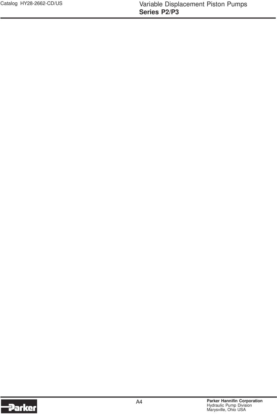
6 Technical Information Series P2/P3 Technical Data P2 Series P3 Series Frame size P26 P275 P215 P2145 P375 P315 P3145 Max displacement cm³/rev [cu in/rev] Self-priming speed at 1 bar/14.5 psi abs. inlet pressure [rpm] Max continuous pressure bar [psi] Peak pressure bar [psi] Minimum Inlet Pressure bar abs at max speed [in Hg vacuum] Maximum Inlet Pressure bar [psi] Maximum Case Drain Pressure bar continuous psi Noise level at full flow, 18 rpm, and 25 bar (36 psi) [dba] Weight with load sense control kg [lbs] Mass moment of inertia kg m (about axis of shaft) A8
![inlet pressure [rpm] 28 25 23 22 3 26 25 Max continuous pressure bar 32 32 32 32 32 32 32 [psi] 46 46 46 46 46 46 46 Peak pressure bar 37 37 37 37 37 37 37 [psi] 5365 5365 5365 5365 5365 5365 5365](/docs-images/46/21240011/images/page_6.jpg "Minimum Inlet Pressure bar abs.8.8.8.8.8.8.8 at max speed [in Hg vacuum] 5.8 5.8 5.8 5.8 5.8 5.8 5.8 Maximum Inlet Pressure bar 1 1 1 1 1.5 1.5 1.5 [psi] 145 145 145 145 22.7 22.")
7 Technical Information Series P2/P3 P2/P3 Typical Control Characteristics Typical Response Times Input Speed: 15 RPM Fluid: Mineral Oil ISO VG 4º C Pressure Condition Stand by to 25 bar to 5 bar to Stand by 3 bar to 25 bar stand by stand by to 3 bar stand by Flow Condition TA (ms) TR (ms) TR (ms) TA (ms) TR (ms) Size -1% 1%- 1%- -1% 1%- P P P P P P P Differential Setting vs Standby Pressure Standby Pressure (bar) P26 All Others This chart shows the difference between differential pressure setting and stand by pressure. The P26 utilizes a different control from the rest of the product family. All others refers to all other pump sizes P2 and P3 75 thru Differential Setting (bar) A9

8 Technical Information Series P2/P3 Control Option PA Pressure Compensator Control The pressure compensator control is used to limit the maximum system pressure. The control acts such that full pump displacement is achieved unless the system valve restricts the output flow or the load pressure reaches the maximum setting of the control. If pump flow is restricted by the system valve, the pump will provide only the flow demanded, but at the maximum pressure setting of the compensator control. If the outlet flow is completely blocked, the pump will destroke to zero displacement and maintain the pressure at the setting of the compensator spring. Q P Control drain port (connect to tank) T OUT OUT IN IN P2 Control Schematic P3 Control Schematic A1

9 Technical Information Series P2/P3 Control Option RA Remote Pressure Compensator Control This control allows the pump pressure compensator setting to be adjusted from a remote relief valve. The control acts such that full pump displacement is achieved unless the system valve restricts the output flow or the load pressure reaches the maximum setting of the control. If pump flow is restricted by the system valve, the pump will provide only the flow demanded, but at the maximum pressure setting of the compensator control. If the outlet flow is completely blocked, the pump will destroke to zero displacement and maintain the pressure at the setting of the remote relief valve. Q P X Port (connect load sense line here) X Port (connect remote sense line here) X T OUT OUT IN IN P2 Control Schematic P3 Control Schematic A11

10 Technical Information Series P2/P3 Control Options LA and LB Load sensing controls with maximum pressure cut off These controls feature load sensing and maximum pressure compensation. Load sense controls are used to match pump flow and pressure to system demands, thus minimizing losses due to wasted horsepower. The pump automatically adjusts for changes in drive speed and load pressures to match the pump output flow to the load requirement. Since the pump load sense control will maintain a constant pressure drop across the main system throttling valve, the flow rate will remain constant, independent of changes in load pressure and pump shaft speed. Q P X Port (connect load sense line here) Control drain port (connect to tank) X Port (connect load sense line here) X T Bleed orifice for "LB" control (plugged on "LA" control) Bleed orifice ("LB" control only) OUT OUT IN P2 Control Schematic IN P3 Control Schematic A12

11 Technical Information Series P2/P3 Control Options TA, TB, TC and TD Torque limiting control with load sensing and maximum pressure limiter Q These controls provide the benefits of the load sensing and pressure limiting controls, plus the ability to limit the input torque the pump will draw. These controls are beneficial when the power available from the prime mover for the hydraulics is limited or the application power demand has both high flow / low pressure and low flow / high pressure duty cycles. P X Port (connect load sense line here) Bleed orifice for "TB" & "TD" (plugged on "TA" & "TC") Control drain port (connect to tank) X port (connect load sense line here) X T Bleed orifice for "TB"& "TD" control (plugged on "TA" & "TC"control) OUT OUT IN IN P2 Control Schematic P3 Control Schematic * See following pages for typical control characteristics A13

12 Performance Data Series P2/P3 Ripple Chamber Pressure 2 BAR (29 PSI) 3 (435) Ripple BAR (psi) 2 (29) 1 (145) Without Ripple Chamber With Ripple Chamber Speed (RPM) The chart above refers to the Ripple Chamber technology that has been engineered into the P2 and P3 series pumps. The ripple chamber reduces pressure pulsation ripple at the outlet of the pump. This technology reduces the ripple by 4 6%. This leads to a significant reduction in overall system noise without additional components or cost. The ripple chamber is standard on all P2 and P3 series side ported pumps. A14

13 Performance Data Series P2 P2 Series Typical Torque Control Characteristics Fluid: Mineral oil ISO VG 4 C Inlet pressure: 1. Bar (14.5 PSI) (Absolute) measured at inlet port. 133 (35) P26 2-6% Torque 18 RPM 133 (35) P26 5-9% Torque 18 RPM 113 (3) 113 (3) 95 (25) 95 (25) Flow l/min (GPM) 76 (2) 57 (15) 38 (1) 2% 3% 6% 5% 4% Flow l/min (GPM) 76 (2) 57 (15) 38 (1) 8% 7% 6% 5% 14 (5) 14 (5) 7 (1) 14 (2) 21 (3) 275 (4) 345 (5) 7 (1) 14 (2) 21 (3) 275 (4) 345 (5) 151 (4) P % Torque 18 RPM 151 (4) P % Torque 18 RPM 133 (35) 133 (35) Flow l/min (GPM) 113 (3) 95 (25) 76 (2) 57 (15) 38 (1) 14 (5) 7 (1) 14 (2) 21 (3) 275 (4) 6% 5% 4% 3% 2% 345 (5) Flow l/min (GPM) 113 (3) 95 (25) 76 (2) 57 (15) 38 (1) 14 (5) 7 (1) 14 (2) 21 (3) 275 (4) 8% 7% 6% 5% 345 (5) A15
 95 (25) 76 (2) 57 (15) 38 (1) 14 (5) 7 (1) 14 (2) 21 (3) 275 (4) 6% 5% 4% 3% 2% 345 (5) Flow l/min (GPM) 113 (3) 95 (25) 76 (2) 57 (15) 38 (1) 14 (5) 7 (1) 14 (2) 21 (3) 275 (4) 8% 7%")
14 Performance Data Series P2 P2 Series Typical Torque Control Characteristics Fluid: Mineral oil ISO VG 4 C Inlet pressure: 1. Bar (14.5 PSI) (Absolute) measured at inlet port. 227 (6) P % Torque 18 RPM 227 (6) P % Torque 18 RPM 189 (5) 189 (5) 151 (4) 151 (4) Flow l/min (GPM) 113 (3) 76 (2) 6% 5% Flow l/min (GPM) 113 (3) 76 (2) 8% 7% 6% 5% 38 (1) 2% 3% 4% 38 (1) 7 (1) 14 (2) 21 (3) 275 (4) 345 (5) 7 (1) 14 (2) 21 (3) 275 (4) 345 (5) 33 (8) P % Torque 18 RPM 33 (8) P % Torque 18 RPM 265 (7) 265 (7) 227 (6) 227 (6) Flow l/min (GPM) 189 (5) 151 (4) 113 (3) 76 (2) 38 (1) 2% 6% 5% 4% 3% Flow l/min (GPM) 189 (5) 151 (4) 113 (3) 76 (2) 38 (1) 8% 7% 6% 5% 7 (1) 14 (2) 21 (3) 275 (4) 345 (5) 7 (1) 14 (2) 21 (3) 275 (4) 345 (5) A16 n
 189 (5) 151 (4) 113 (3) 76 (2) 38 (1) 2% 6% 5% 4% 3% Flow l/min (GPM) 189 (5) 151 (4) 113 (3) 76 (2) 38 (1) 8% 7% 6% 5% 7 (1) 14 (2) 21 (3) 275 (4) 345 (5) 7 (1) 14 (2) 21 (3) 275 (4)")
15 Performance Data Series P2 P2 Series Typical Noise Characteristics at Max Displacement (These are anechoic sound pressure readings.) Fluid: Mineral oil ISO VG 4 C Inlet pressure: 1. Bar (14.5 PSI) (Absolute) measured at inlet port. P2-6 Noise Characteristics P2-75 Noise Characteristics Noise d(b)a RPM Noise d(b)a RPM 7 15 RPM 7 15 RPM 65 7 (1) 14 (2) 21 (3) 275 (4) 32 (46) 65 7 (1) 14 (2) 21 (3) 275 (4) 32 (46) 9 P2-15 Noise Characteristics 9 P2-145 Noise Characteristics RPM 85 Noise (dba) RPM Noise d(b)a RPM 15 RPM (1) 14 (2) 21 (3) 275 (4) 32 (46) 7 (1) 14 (2) 21 (3) 275 (4) 32 (46) A17
 65 7 (1) 14 (2) 21 (3) 275 (4) 32 (46) 9 P2-15 Noise Characteristics 9 P2-145 Noise Characteristics 85 23 RPM 85 Noise (dba) 8 75 15 RPM Noise d(b)a 8 75 22")
16 Performance Data Series P2 P2 Series Typical Drive Power at Full Displacement Fluid: Mineral oil ISO VG 4 C Inlet pressure: 1. Bar (14.5 PSI) (Absolute) measured at inlet port. P26 Input Power - Full Stroke P275 Input Power - Full Stroke 1 (134) 9 (121) 8 (17) 28 RPM 25 RPM 12 (161) 1 (134) 25 RPM kw (HP) 7 (94) 6 (8) 5 (67) 4 (54) 3 (4) 2 (27) 1 (13) 18 RPM 15 RPM 12 RPM 1 RPM 6 RPM kw (HP) 8 (17) 6 (8) 4 (54) 2 (27) 18 RPM 15 RPM 12 RPM 1 RPM 6 RPM 5 1 (145) 15 (2175) 2 (29) 25 3 (435) 35 (575) 5 1 (145) 15 2 (2175) (29) 25 3 (435) 35 (575) P215 Input Power - Full Stroke P2145 Input Power - Full Stroke 16 (215) 2 (268) kw (HP) 14 (188) 12 (161) 1 (134) 8 (17) 6 (8) 4 (54) 2 (27) 23 RPM 18 RPM 15 RPM 12 RPM 1 RPM 6 RPM kw (HP) 18 (241) 16 (215) 14 (188) 12 (161) 1 (134) 8 (17) 6 (8) 4 (54) 2 (27) 22 RPM 18 RPM 15 RPM 12 RPM 1 RPM 6 RPM 5 1 (145) 15 (2175) 2 (29) 25 3 (435) 35 (575) 5 1 (145) 15 (2175) 2 (29) 25 3 (435) 35 (575) A18
 2 (268) kw (HP) 14 (188) 12 (161) 1 (134) 8 (17) 6 (8) 4 (54) 2 (27) 23 RPM 18 RPM 15 RPM 12 RPM 1 RPM 6 RPM kw (HP) 18 (241) 16 (215) 14 (188) 12")
17 Performance Data Series P2 P2 Series Typical Compensated Power Fluid: Mineral oil ISO VG 4 C Inlet pressure: 1. Bar (14.5 PSI) (Absolute) measured at inlet port. P26 Input Power - Zero Stroke P275 Input Power - Zero Stroke 14 (19) 28 rpm 16 (21) 12 (17) 25 rpm 14 (19) 25 rpm 1 (13) 12 (17) kw (HP) 8 (11) 6 (8) 4 (5) 18 rpm 15 rpm 12 rpm 1 rpm 6 rpm kw (HP) 1 (13) 8 (11) 6 (8) 4 (5) 18 rpm 15 rpm 12 rpm 1 rpm 6 rpm 2 (3) 2 (3) 5 1 (145) 15 (2175) 2 (29) 25 3 (435) 35 (575) 5 1 (145) 15 (2175) 2 (29) 25 3 (435) 35 (575) P215 Input Power - Zero Stroke P2145 Input Power - Zero Stroke 16 (21) 14 (19) 12 (17) 23 rpm 18 rpm 25 (36) 2 (27) 22 rpm kw (HP) 1 (13) 8 (11) 6 (8) 4 (5) 2 (3) 15 rpm 12 rpm 1 rpm 6 rpm kw (HP) 15 (2) 1 (13) 5 (7) 18 rpm 15 rpm 12 rpm 1 rpm 6 rpm 5 1 (145) 15 (2175) 2 (29) 25 3 (435) 35 (575) 5 (725 1 (145) 15 (2175) 2 (29) 25 3 (435) 35 (575) A19
 14 (19) 12 (17) 23 rpm 18 rpm 25 (36) 2 (27) 22 rpm kw (HP) 1 (13) 8 (11) 6 (8) 4 (5) 2 (3) 15 rpm 12 rpm 1 rpm 6 rpm kw (HP) 15 (2) 1 (13) 5 (7) 18 rpm 15 rpm 12")
18 Performance Data Series P2 P2 Series Typical Efficiency at Full 18 RPM Fluid: Mineral oil ISO VG 4 C Inlet pressure: 1. Bar (14.5 PSI) (Absolute) measured at inlet port. P26 Efficiency at 18 RPM P275 Efficiency at 18 RPM 1 Volumetric 1 Volumetric 9 Overall 9 Overall Efficiency (%) 8 7 Efficiency (%) (145) 15 (2175) 2 (29) 25 3 (435) 35 (575) (145) 15 (2175) 2 (29) 25 3 (435) 35 (575) P215 Efficiency at 18 RPM P2145 Efficiency at 18 RPM 1 1 Volumetric Volumetric 9 Overall 9 Overall Efficiency (%) 8 7 Efficiency (%) (145) 15 (2175) 2 (29) 25 3 (435) 35 (575) (145) 15 (2175) 2 (29) 25 3 (435) 35 (575) A2
 25 3 (435) 35 (575) 5 5 1 (145) 15 (2175) 2 (29) 25 3 (435) 35 (575) P215 Efficiency at 18 RPM P2145 Efficiency at 18 RPM 1 1 Volumetric Volumetric 9 Overall 9")
19 Performance Data Series P2 P2 Series Typical Flow vs. Pressure Fluid: Mineral oil ISO VG 4 C Inlet pressure: 1. Bar (14.5 PSI) (Absolute) measured at inlet port. P26 Outlet Flow - Full Stroke P275 Outlet Flow - Full Stroke Flow L/min (GPM) 18 (48) 16 (42) 14 (37) 12 (32) 1 (26) 8 (21) 6 (16) 4 (11) 2 (5) 28 rpm 25 rpm 18 rpm 15 rpm 12 rpm 1 rpm 6 rpm Flow L/min (GPM) 2 (53) 18 (48) 16 (42) 14 (37) 12 (32) 1 (26) 8 (21) 6 (16) 4 (11) 2 (5) 25 rpm 18 rpm 15 rpm 12 rpm 1 rpm 6 rpm 5 1 (145) 15 (2175) 2 (29) 25 3 (435) 35 (575) 5 1 (145) 15 (2175) 2 (29) 25 3 (435) 35 (575) P215 Outlet Flow - Full Stroke P2145 Outlet Flow - Full Stroke 3 (79) 35 (92) Flow L/min (GPM) 25 (66) 2 (53) 15 (4) 1 (26) 23 rpm 18 rpm 15 rpm 12 rpm 1 rpm 6 rpm Flow L/min (GPM) 3 (79) 25 (66) 2 (53) 15 (4) 1 (26) 22 rpm 18 rpm 15 rpm 12 rpm 1 rpm 6 rpm 5 (13) 5 (13) 5 1 (145) 15 (2175) 2 (29) 25 3 (435) 35 (575) 5 1 (145) 15 (2175) 2 (29) 25 3 (435) 35 (575) A21
 35 (575) P215 Outlet Flow - Full Stroke P2145 Outlet Flow - Full Stroke 3 (79) 35 (92) Flow L/min (GPM) 25 (66) 2 (53) 15 (4) 1 (26) 23 rpm 18 rpm 15 rpm 12 rpm 1 rpm 6 rpm Flow L/min")
20 Performance Data Series P2 P2 Series Typical Compensated Case Drain Flow Fluid: Mineral oil ISO VG 4 C Inlet pressure: 1. Bar (14.5 PSI) (Absolute) measured at inlet port. 5. (1.3) 4.5 (1.2) 4. (1.) 3.5 (.92) 3. (.79) 2.5 (.66) 2. (.53) 1.5 (.4) 1. (.26).5 (.13) 5 Flow L/min (GPM) P26 Drain Flow at Zero Stroke 1 (145) 15 (2175) 2 (29) rpm 6 rpm 3 (435) 35 (575) Flow L/min (GPM) 14 (3.7) 12 (3.2) 1 (2.6) 8 (2.1) 6 (1.6) 4 (1.) 2 (.53) 5 P275 Drain Flow at Zero Stroke 1 (145) 15 (2175) 2 (29) 25 3 (435) 25 rpm 6 rpm 35 (575) Flow L/min (GPM) 9 (2.4) 8 (2.1) 7 (1.8) 6 (1.6) 5 (1.3) 4 (1.) 3 (.79) 2 (.53) 1 (.26) 5 P215 Drain Flow at Zero Stroke 1 (145) 15 (2175) 2 (29) 25 3 (435) 23 rpm 6 rpm 35 (575) Flow L/min (GPM) 2 (5.3) 18 (4.8) 16 (4.2) 14 (3.7) 12 (3.2) 1 (2.6) 8 (2.1) 6 (1.6) 4 (1.) 2 (.53) 5 P2145 Drain Flow at Zero Stroke 1 (145) 15 (2175) 2 (29) 25 3 (435) 22 rpm 6 rpm 35 (575) A22
 4 (1.) 3 (.79) 2 (.53) 1 (.26) 5 P215 Drain Flow at Zero Stroke 1 (145) 15 (2175) 2 (29) 25 3 (435) 23 rpm 6 rpm 35 (575) Flow L/min (GPM) 2 (5.3) 18 (4.8) 16 (4.2) 14 (3.7) 12 (3.2) 1 (2.6) 8 (2.")
21 Performance Data Series P2 P2 Series Typical Inlet Characteristics vs. Speed at various percentage displacements Fluid: Mineral oil ISO VG 4 C Inlet pressure: 1. Bar (14.5 PSI) measured at inlet port. P26 Inlet Characteristics P275 Inlet Characteristics % 85% % 85% 1% Shaft Speed (RPM) % Shaft Speed (RPM) Sea Level Sea Level (-6) (-4) (-2) (2) (4) Elevation M(ft.) 122 (4) (-4) (-2) () (2) (4) (6) 244 (8) (-2) () (2) (4) (6) (8) 366 (12) () (2) (4) (6) (8) (1) Inlet 15 Sea Level Sea Level (-6) (-4) (-2) (2) (4) Elevation M(ft.) 122 (4) (-4) (-2) () (2) (4) (6) 244 (8) (-2) () (2) (4) (6) (8) 366 (12) () (2) (4) (6) (8) (1) Inlet P215 Inlet Characteristics P2145 Inlet Characteristics 3 7% % 275 7% Shaft Speed (RPM) % Shaft Speed (RPM) % 1% Sea Level Sea Level (-6) (-4) (-2) (2) (4) Elevation M(ft.) 122 (4) (-4) (-2) () (2) (4) (6) 244 (8) (-2) () (2) (4) (6) (8) 366 (12) () (2) (4) (6) (8) (1) Inlet 15 Sea Level Sea Level (-6) (-4) (-2) (2) (4) Elevation M(ft.) 122 (4) (-4) (-2) () (2) (4) (6) 244 (8) (-2) () (2) (4) (6) (8) 366 (12) () (2) (4) (6) (8) (1) Inlet For operation at these speeds, please consult factory for approval. A23
22 Dimensional Data Series P2 Pump Installation - P2-6 Mounting Flange (side port) Inlet Gauge Port Port Options Drain Port Outlet Gauge Port Signal Port SAE-1 Straight Thread SAE-4 Straight Thread A O-ring Port O-ring Port Side - UNC 7/8-14 UN Thread 7/16-2 UN Thread ISO 6149 Straight Thread ISO 6149 Straight Thread B O-ring Port O-ring Port Side - Metric M22 x 1.5 Thread M12 x 1.5 Thread SAE B 2-BOLT MOUNTING FLANGE - DIAGONAL MOUNT 7 (2.76) Drain Port Max Vol Adj 4.1 CC/Turn Sensitivity 3 CC Min 9.5 (.37) 5 2 Places 81 (3.19) 11.6/11.55 (4./3.998) (5.75) B.C. 15 (.59) SAE C 4-BOLT MOUNTING FLANGE (4.51) 235 (9.25) 12.5 (.492) Outlet Gauge Port o/ 127./ (5./4.998) 5 (1.97) (4.51) CCW Pump will have inlet and outlet gauge ports reversed. 15 (.59) 223 (8.78) Inlet Gauge Port A24
23 Dimensional Data Series P2 Pump Installation - P2-6 Side Port Inlet Gauge Port Port Options Drain Port Inlet Port Outlet Port Outlet Gauge Port Signal Port SAE-12 Straight Thread SAE-4 Straight Thread A O-ring Port 1/2-13 UN 7/16-14 UN O-ring Port Side - UNC 1-1/16-12 Thread 7/16-2 UN Thread ISO 6149 Straight Thread ISO 6149 Straight Thread B O-ring Port M12 x 1.75 M12 x 1.75 O-ring Port Side - Metric M27 x 2 Thread M12 x 1.5 Thread TOP VIEW Outlet Port 1" 4 Bolt Flange High Pressure Series (Code 62) Thread Size See Chart 235 (9.25) Lifting Hook (3/8-16 Thread) 66 (2.59) 141 (5.55) 73 (2.87) 49 (1.93) REAR VIEW 66 (2.6) 45 (1.77) 92 (3.62) 144 (5.67) 124 (4.88) 96 (3.78) 76 (3.) Diff Pressure Adj 1.7BAR (155PSI) Per Turn Sensitivity Pressure Comp Adj 52BAR (758PSI) Per Turn Sensitivity Signal Port see Chart 81 (3.19) 252 (9.92) 184 (7.24) SIDE VIEW 78 (3.7) 29 (1.14) "Weep Hole" Wet Flange Both Sides Seal Option D & T (4.49) 73 (2.87) Ripple Chamber Plug DO NOT REMOVE 81 (3.19) 114 (4.49) 9 (3.54) 51 (2.) 73 (2.87) 76 (3.3) 52 (2.5) 73 (2.87) 85 (3.45) Rotation Arrow Ripple Chamber Plug DO NOT REMOVE Optional Drain Port See Chart BOTTOM VIEW 71 (2.8) 19 (4.29) 126 (4.96) 163 (6.41) Thread Size See Chart Inlet Port 2" 4 Bolt Flange Standard Pressure Series (Code 61) A (8.82) 264 (1.39)
24 Dimensional Data Series P2 Pump Installation - P2-6 Mounting Flange (rear port) SAE B 2-BOLT MOUNTING FLANGE - DIAGONAL MOUNT 7 (2.76) Drain Port Max Vol Adj 4.1 CC/Turn Sensitivity 3 CC Min 9.5 (.37) 5 2 Places 81 (3.19) 11.6/11.55 (4./3.998) (5.75) B.C. 15 (.59) SAE C 4-BOLT MOUNTING FLANGE (4.51) 12.5 (.492) 7 (2.76) Max Vol Adj 4.1 CC/Turn Sensitivity 3 CC Min (4.51) 127 (5.) Inlet gauge port. See table page (.59) CCW Pump will have inlet and outlet gauge ports reversed. Does not include Ripple Chamber. A26
25 Dimensional Data Series P2 Pump Installation - P2-6 Rear Port Inlet Gauge Port Port Options Drain Port Inlet Port Outlet Port Outlet Gauge Port Signal Port SAE-12 Straight Thread SAE-4 Straight Thread G O-ring Port 1/2-13 UN 7/16-14 UN O-ring Port Rear - UNC 1-1/16-12 Thread 7/16-2 UN Thread ISO 6149 Straight Thread ISO 6149 Straight Thread H O-ring Port M12 x 1.75 M12 x 1.75 O-ring Port Rear - Metric M27 x 2 Thread M12 x 1.5 Thread TOP VIEW Lifting Hook (3/8-16 UN-2B Thread) 66 (2.6) 141 (5.55) 14 (4.9) 49 (1.93) REAR VIEW 92 (3.62) 66 (2.6) 45 (1.77) 144 (5.67) 124 (4.88) 96 (3.78) 76 (3.) Signal Port 252 (9.92) 184 (7.24) SIDE VIEW 11 (3.98) 78 (3.7) 29 (1.14) "Weep Hole" Both Sides Seal Option D & V Inlet Port 2" 4 Bolt Flange Standard Press Series (Code 61) Outlet Port 1" 4 Bolt Flange High Press Series (Code 62) Thread Size See Table 14 (4.9) 9 (3.54) 114 (4.89) Thread Size See Table 39 (1.53) 79.3 (3.12) 5 (1.97) 79.3 (3.12) Outlet Optional Gauge Drain Port Port See table (6.41) 211 (2.31) (4.76) 71 (2.8) 19 (4.29) BOTTOM VIEW 1. Pump shown is a clockwise rotation P2-6 series axial piston pump with load sense and maximum pressure. 2. CCW rotation pump will have inlet and outlet ports reversed. 241 (9.49) A27
26 Dimensional Data Series P2 Pump Installation - P2-6 Thru-Shaft Option Thru-Shaft A B C D E F F G G Pump Option UNC Metric UNC Metric Weight / SAE-A Spline A N/A 9 Tooth 3/8-16 UNC-2B THD M1 x 1.5 THD N/A N/A 36.2 kg (1.4) (3.252/ (4.19) 16/32 Pitch (8 lbs) 3.25) / SAE-B Spline B N/A 13 Tooth 1/2-13 UNC-2B THD M12 x 1.75 THD N/A N/A 38.9 kg (11.7) (4.2/ (5.75) 16/32 Pitch (86 lbs) 4.) / SAE-BB Spline B N/A 15 Tooth 1/2-13 UNC-2B THD M12 x 1.75 THD N/A N/A 38.9 kg (11.7) (4.2/ (5.75) 16/32 Pitch (86 lbs) 4.) / SAE-C Spline C1 C Tooth 5/8-11 UNC-2B THD M16 x 2 THD 1/2-13 UNC-2B THD M12 x 1.75 THD 4.2 kg (11.8) (5.2/ (7.125) (4.58) 12/24 Pitch (89 lbs) 5.) A1 CONFIGURATION B1 & B2 CONFIGURATION E E F C B B F C C1 & C3 CONFIGURATION A 264 (1.39) F G E D C B E D Max Thru-Drive Torque is 336 Nm (298 lb in) A28
27 Dimensional Data Series P2 Pump Installation - P2-75 Mounting Flange Inlet Gauge Port Port Options Drain Port Outlet Gauge Port SAE-12 Straight Thread SAE-4 Straight Thread A O-ring Port O-ring Port Side - UNC 1-1/16-12 UN Thread 7/16-2 UN Thread ISO 6149 Straight Thread ISO 6149 Straight Thread B O-ring Port O-ring Port Side - Metric M27 x 2 Thread M12 x 1.5 Thread FLANGE MOUNTING DIMENSIONS - SIDE PORTED PUMP (1.96) (1.41) Drain Port Max Vol Adj 4.9 CC/Turn Sensitivity SAE C 2 Bolt Mounting Holes 2 Places (.692) Diameter 76 (3.) Outlet Gauge Port 194 (7.63) 127. (5.) (4.99) 32.4 (1.28) 62 (2.44) 62 (2.44) 146 (5.75) SAE C 4 Bolt Mounting Holes (.565) Diameter (1.17) Inlet Gauge Port FLANGE MOUNTING DIMENSIONS - REAR PORTED PUMP SAE C 2 Bolt Mounting Holes 2 Places (.692) Diameter 76 (3.) 6.5 (2.38) (1.96) Drain Port Max Vol Adj 4.9 CC/Turn Sensitivity 52 CC Min 194 (7.64) (4.51) 127. (5.) (4.99) 81 (3.19) 123 (4.84) Inlet Gauge Port CCW Pump will have inlet and outlet gauge ports reversed. 146 (5.75) (4.51) SAE C 4 Bolt Mounting Holes (.565) Diameter 88.2 (3.47) (9.78) 27.5 (1.65) A29
28 Dimensional Data Series P2 Pump Installation - P2-75 Side Port TOP VIEW "A" 7/16-14 UNC "B" M12X (1.43) Outlet Port 1" High Press Series 4 Bolt Flange (Code 62) 67.5 (2.66) REAR VIEW 21 (7.91) Signal Port "A" SAE-4 Straight Thread O-Ring Port 7/16-2 UNC "B" ISO 6149 Straight Thread O-Ring Port, M12 x (5.71) 55 (2.17) 112 (4.41) 84.5 (3.33) 52 (2.5) 77.5 (3.5) 13 (5.12) 99 (.39) 154 (6.6) Diff Press Adj 9.1 Bar (131psi) Per Turn Sensitivity Press Comp Adj 63.5 Bar (921 psi) Per Turn Sensitivity 81 (3.19) SIDE VIEW 12.5 (4.4) 6.5 (2.38) Weep hole for D & T 123 (4.84) 81 (3.19) 95 (3.19) 51 (2.) 81 (3.19) 51 (2.) 9.5 (3.56) Dimensions Will Be Reversed On A CCW Pump Rotation Arrow Ripple Chamber Plug DO NOT REMOVE Alternate Drain Port BOTTOM VIEW 88.2 (3.47) (4.98) Inlet Port 2" Standard Press Series 4 Bolt Flange (Code 61) "A" 1/2-13 UNC "B" M12X1.75 CCW Pump will have inlet and outlet gauge ports reversed. 254 (1.) (11.52) A3
29 Dimensional Data Series P2 Pump Installation - P2-75 Rear Port Inlet Gauge Port Port Options Drain Port Inlet Port Outlet Port Outlet Gauge Port Signal Port SAE-12 Straight Thread SAE-4 Straight Thread G O-ring Port 1/2-13 UN 7/16-14 UN O-ring Port Rear - UNC 1-1/16-12 Thread 7/16-2 UN Thread ISO 6149 Straight Thread ISO 6149 Straight Thread H O-ring Port M12 x 1.75 M12 x 1.75 O-ring Port Rear - Metric M27 x 2 Thread M12 x 1.5 Thread TOP VIEW 67.5 (2.66) 84.5 (3.33) REAR VIEW Signal Port 21 (7.91) 55 (2.17) 39 (1.54) 84.5 (3.33) 52 (2.4) 112 (4.41) Diff Press Adj 9.1 BAR (132 PSI) Per Turn Sensitivity 4mm Hex SIDE VIEW 12.5 (4.4) Press Comp Adj 63.5 BAR (921PSI)/ Turn Sensitivity 4mm Hex 145 (5.71) Outlet Port 1" High Press Series 4 Bolt Flange (Code 62) Inlet Gauge Port 51 (2.) 81.8 (3.22) Inlet Port 2" Standard Press Series 4 Bolt Flange (Code 61) 51 (2.) 81.8 (3.22) (9.78) BOTTOM VIEW Optional Drain Port 1. Pump shown is a clockwise rotation P2-75 series axial piston pump with load sense and maximum pressure. 2. CCW rotation pump will have inlet and outlet ports reversed (1.65) A31
30 Dimensional Data Series P2 Pump Installation - P2-75 Thru-Shaft Option Thru-Shaft A B C D E F F G G Pump Option UNC Metric UNC Metric Weight / SAE-A Spline A N/A 9 Tooth 3/8-16 UNC-2B THD M1 x 1.5 THD N/A N/A 44 kg (1.4) (3.252/ (4.19) 16/32 Pitch (97 lbs) 3.25) / SAE-B Spline B N/A 13 Tooth 1/2-13 UNC-2B THD M12 x 1.75 THD N/A N/A 46.5 kg (11.7) (4.2/ (5.75) 16/32 Pitch (12.5 lbs) 4.) / SAE-BB Spline B N/A 15 Tooth 1/2-13 UNC-2B THD M12 x 1.75 THD N/A N/A 46.5 kg (11.7) (4.2/ (5.75) 16/32 Pitch (12.5 lbs) 4.) / SAE-C Spline C1 C Tooth 5/8-11 UNC-2B THD M16 x 2 THD 1/2-13 UNC-2B THD M12 x 1.75 THD 48 kg (11.8) (5.2/ (7.125) (4.58) 12/24 Pitch (15.9 lbs) 5.) A1 CONFIGURATION B1 & B2 CONFIGURATION F C F B B (4.19) C1 & C3 CONFIGURATION F C D E B 88 (3.46) D Ref A Max Thru-Drive Torque is 336 Nm (2973 lb in) Pumps will be assembled with flange adapters as shown. Options B1, B2, C1 and C3 can be rotated 9º. A32
31 Dimensional Data Series P2 Pump Installation - P2-15 Mounting Flange Inlet Gauge Port Port Options Drain Port Outlet Gauge Port SAE-12 Straight Thread SAE-4 Straight Thread A O-ring Port O-ring Port Side - UNC 1-1/16-12 UN-2B 7/16-2 UN Thread ISO 6149 Straight Thread ISO 6149 Straight Thread B O-ring Port O-ring Port Side - Metric M27 x 2 Thread M12 x 1.5 Thread 3 Drain Port SAE C 2-Bolt Mounting Holes 2 Places 95 (3.74) Max Vol Adj 5.65CC/Turn Sensitivity Min Disp 7CC/Rev Outlet Gauge Port 194 (7.64) SAE C 4-Bolt Mounting Flange 13 (4.6) 97 (3.82) (4.51) 181 (7.125) 12 (4.2) Inlet Gauge Port (4.5) 277 (1.91) 146 (5.75) CCW Pump will have inlet and outlet gauge ports reversed. A33
32 Dimensional Data Series P2 Pump Installation - P2-15 Side Port Inlet Gauge Port Port Options Drain Port Inlet Port Outlet Port Outlet Gauge Port Signal Port SAE-12 Straight Thread SAE-4 Straight Thread A O-ring Port 1/2-13 UN 1/2-13 UN O-ring Port Side - UNC 1-1/16-12 UN-2B 7/16-2 UN Thread ISO 6149 Straight Thread ISO 6149 Straight Thread B O-ring Port M12 x 1.75 M12 x 1.75 O-ring Port Side - Metric M27 x 2 Thread M12 x 1.5 Thread Outlet Port 1-1/4 Inch High Press Series 4 Bolt Flange (Code 62) 292 (11.5) TOP VIEW 12.5 (.49) 68 (2.69) REAR VIEW 55 (2.17) 112 (4.41) 85 (3.25) 52 (2.5) 175 (6.89) 151 (5.94) 12 (4.72) 98 (3.86) Diff Pressure Adj 9.1 BAR (131PSI) /Turn Sensitivity Pressure Comp Adjustment 63.5 BAR (921PSI)/ Turn Sensitivity 97 (3.82) Signal Port 294 (11.57) 216 (8.5) SIDE VIEW 118 (4.65) Weep Hole D&T Option (5.91) Rotation Arrow 12 (4.2) 115 (4.53) 15 (5.91) 57 (2.24) 1 (3.94) 57 (2.24) 111 (4.37) Ripple Chamber Plug DO NOT REMOVE Optional Drain 148 (5.83) BOTTOM VIEW Dimensons will be reversed on a counterclockwise pump. Inlet Port 2-1/2 Inch High Press Series 4 Bolt Flange (Code 61) A (1.91) 323 (12.72)
33 Dimensional Data Series P2 Pump Installation - P2-15 Thru-Shaft Option Thru-Shaft A B C D E F F G G Pump Option UNC Metric UNC Metric Weight Ø / SAE-A Spline A N/A 9 Tooth 1/2-13 UNC-2B THD M1 x 1.5 THD N/A N/A 61 (12.72) (3.252/ (4.19) 16/32 Pitch (134) 3.25) Ø / SAE-B Spline B N/A 13 Tooth 1/2-13 UNC-2B THD M12 x 1.75 THD N/A N/A 64 (14.2) (4.2/ (5.75) 16/32 Pitch (14) 4.1) Ø / SAE-BB Spline B N/A 15 Tooth 1/2-13 UNC-2B THD M12 x 1.75 THD N/A N/A 64 (14.2) (4.2/ (5.75) 16/32 Pitch (14) 4.1) Ø / SAE-C Spline C Tooth 1/2-13 UNC-2B THD M12 x 1.75 THD 5/8-11 UNC-2B THD M16 x 2 THD 65 (14.9) (5.3/ (7.13) /24 Pitch (143) 5.1) Ø / SAE-C Spline C Tooth 1/2-13 UNC-2B THD M12 x 1.75 THD 5/8-11 UNC-2B THD M16 x 2 THD 65 (14.9) (5.3/ (7.13) /24 Pitch (143) 5.1) * All shaft Couplings 3 Degrees Involute Spline Flat Root Side Fit *** Maximum Thru Drive Capability is Limited to 587Nm (5195 lb in) A1 CONFIGURATION B1 & B2 CONFIGURATION E E E F C B B C C1 & C3 CONFIGURATION A 323 (12.72) G F E D C B D A35
34 Dimensional Data Series P2 Pump Installation - P2-145 Mounting Flange Inlet Gauge Port Port Options Drain Port Outlet Gauge Port SAE-12 Straight Thread SAE-4 Straight Thread A O-ring Port O-ring Port Side - UNC 1-1/16-12 UN Thread 7/16-2 UN Thread ISO 6149 Straight Thread ISO 6149 Straight Thread B O-ring Port O-ring Port Side - Metric M27 x 1.75 Thread M12 x 1.5 Thread SAE D 4-BOLT MOUNTING FLANGE 299 (11.77) Outlet Gauge 12.7 (.5) ø 152.4/ (6./5.998) 82 (3.23) (6.36) 9 (3.54) 2 (.79) Inlet Gauge (6.36) 289 (11.38) SAE C 2-BOLT MOUNTING FLANGE 92 (3.62) DRAIN PORT Max Volume Adj 7.8 CC/Turn Sensitivity 1 CC Min 112 (4.41) 12.7 (.5) 127./ (5./4.998) 15 (.59) CCW Pump will have inlet and outlet gauge ports reversed (7.125) A36
35 Dimensional Data Series P2 Pump Installation - P2-145 Side Port Inlet Gauge Port Port Options Drain Port Inlet Port Outlet Port Outlet Gauge Port Signal Port SAE-12 Straight Thread SAE-4 Straight Thread A O-ring Port 1/2-13 UN 1/2-13 UN O-ring Port Side - UNC 1-1/16-12 UN-2B 7/16-2 UN Thread ISO 6149 Straight Thread ISO 6149 Straight Thread B O-ring Port M12 x 1.75 M12 x 1.75 O-ring Port Side - Metric M27 x 2 Thread M12 x 1.5 Thread Thread: See Table 299 (11.77) 13 (5.12) TOP VIEW Lifting Hook 3/8-16 UN-2B Outlet Port 1-1/4 Inch High Press Series 4 Bolt Flange (Code 62) 7 (2.76) 58 (2.28) REAR VIEW 114 (4.49) 87 (3.43) 54 (2.13) 186 (7.32) 162 (6.38) Diff Pressure Adjustment 9.1 BAR(132PSI)/ Turn Sensitivity Pressure Comp Adjustment 63.5 BAR (921PSI)/ Turn Sensitivity Signal Port 32/292.5 (11.89/11.52) Optional Diff Press Test Port (-4 SAE) 22 (8.66) 64 (2.52) SIDE VIEW 121 (4.76) 98 (3.86) 181 (7.13) 19 (4.29) 131 (5.16) 12 (4.2) 142 (84.33) 164 (6.46) Ripple Chamber Plug DO NOT REMOVE 11 (4.33) Weep Hole Both Sides Seal Option D & T Rotation Arrow 57 (2.24) 1 (3.94) 17 (4.21) 59 (2.32) 1 (3.94) 118 (4.65) Dimensons will be reversed on a counterclockwise pump. Optional Drain Port 284 (11.18) 27 (8.15) 82 (3.23) 127 (5.) BOTTOM VIEW Thread - See Table 118 (4.65) Inlet Port 2-1/2 Inch Std Press Series 4 Bolt Flange (Code 61) 17 (4.21) 33 (13.) A37
36 Dimensional Data Series P2 Pump Installation - P2-145 Thru-Shaft Option Thru-Shaft A B C D E F F G G Pump Option UNC Metric UNC Metric Weight Ø / SAE-A Spline A N/A 9 Tooth 3/8-16 UNC-2B THD M1 x 1.5 THD N/A N/A 79.8 (13.) (3.252/ (4.19) 16/32 Pitch (176) 3.25) Ø / SAE-B Spline B N/A 13 Tooth 1/2-13 UNC-2B THD M12 x 1.75 THD N/A N/A 82.6 (14.27) (4.2/ (5.75) 16/32 Pitch (182) 4.1) Ø / SAE-BB Spline B N/A 15 Tooth 1/2-13 UNC-2B THD M12 x 1.75 THD N/A N/A 82.6 (14.27) (4.2/ (5.75) 16/32 Pitch (182) 4.1) Ø / SAE-C Spline C Tooth 5/8-11 UNC-2B THD M16 x 2 THD 1/2-13 UNC-2B THD M12 x 1.75 THD 83.9 (14.35) (5.3/ (7.13) N/A 12/24 Pitch (185) 5.1) Ø / SAE-C Spline C Tooth 5/8-11 UNC-2B THD M16 x 2 THD 1/2-13 UNC-2B THD M12 x 1.75 THD 83.9 (14.35) (5.3/ (7.13) N/A 12/24 Pitch (185) 5.1) Ø / SAE-C Spline C Tooth 5/8-11 UNC-2B THD M16 x 2 THD 1/2-13 UNC-2B THD M12 x 1.75 THD 83.9 (14.35) (5.3/ (7.13) /24 Pitch (185) 5.1) Ø / SAE-CC Spline C Tooth 5/8-11 UNC-2B THD M16 x 2 THD 1/2-13 UNC-2B THD M12 x 1.75 THD 83.9 (14.35) (5.3/ (7.13) /24 Pitch (185) 5.1) Ø / SAE-D Spline D N/A 13 Tooth N/A N/A 3/4-1 UNC-2B THD M16 x 2 THD 88. (14.76) (6.3/ /16 Pitch (194) 6.1) *** Maximum Thru Drive Capability is Limited to 1217Nm (1777 lb in) A (12.97) E A38
37 Dimensional Data Series P2 Pump Installation - P2-145 Thru-Shaft Option A1 CONFIGURATION B1 & B2 CONFIGURATION E F B B F C E C C1, C2, C3 & C4 CONFIGURATION D3 CONFIGURATION F G G B E D C D B E D D A39
38 Dimensional Data Series P2 Pump Installation- P2 Shaft Options 41.2 (1.62) 46 (1.81) 55.6 (2.19) "B1" Shaft Option SAE "B" Spline 13 Tooth 16/32 Pitch 3 Involute Spline Maximum Input Torque: 29 Nm (1852 lb in) "B2" Shaft Option SAE "B-B" Spline 15 Tooth 16/32 Pitch 3 Involute Spline Maximum Input Torque: 337 Nm (2987 lb in) "C1" Shaft Option SAE "C" Spline 14 Tooth 12/24 Pitch 3 Involute Spline Maximum Input Torque: 641 Nm (5677 lb in) 55.6 (2.19) 62. (2.44) 75.6 (2.98) "C3" Shaft Option SAE "C" Spline No Undercut 14 Tooth 12/24 Pitch 3 Involute Maximum Input Torque: 769 Nm (6812 lb in) 55.6 (2.19) 7.94 (.3125) Square Key 35.3/35.1 (1.39/1.38) 31.75/31.7 "C5" Shaft Option (1.25/1.24) SAE "C" Keyed Maximum Input Torque: 641 Nm (5677 lb in) "C2" Shaft Option SAE "CC" Spline 17 Tooth 12/24 Pitch 3 Involute Maximum Input Torque: 1217 Nm (1777 lb in) 62. (2.44) (.375) Square Key 42.3 (1.66) 38.1 (1.5) "C6" Shaft Option SAE "CC" Keyed Maximum Input Torque: 1217 Nm (1777 lb in) "D1" Shaft Option SAE D 13 Tooth 8/16 Pitch 3 Involute Spline Maximum Input Torque: 171 Nm (1557 lb in) 75.6 (2.98) (.4375) Square Key 49.4 (1.94) 44.4 (1.75) "D3" Shaft Option SAE D Keyed Maximum Input Torque: 171 Nm (1557 lb in) C Torque Control Options "TA","TB","TC & "TD" 2 Nm (177 lb in) Per Turn Approximate Sensitivity B A P2 6 P275 P215 P2145 A (6.42) (6.73) (7.48) (7.95) B (1.33) (2.72) (2.72) (2.72) C (6.34) (6.6) (6.89) (7.32) A4
39 Performance Data Series P3 P3 Series Typical Torque Control Characteristics Fluid: Mineral oil ISO VG 4 C Inlet pressure: 1. Bar (14.5 PSI) (Absolute) measured at inlet port. 151 (4) P % Torque 18 RPM 151 (4) P % Torque 18 RPM 133 (35) 133 (35) Flow l/min (GPM) 113 (3) 95 (25) 76 (2) 57 (15) 38 (1) 14 (5) 7 (1) 14 (2) 21 (3) Pressure (PSI) 275 (4) 6% 5% 4% 3% 2% 345 (5) Flow l/min (GPM) 113 (3) 95 (25) 76 (2) 57 (15) 38 (1) 14 (5) 7 (1) 14 (2) 21 (3) Pressure (PSI) 275 (4) 8% 7% 6% 5% 345 (5) 227 (6) P % Torque 18 RPM 227 (6) P % Torque 18 RPM 189 (5) 189 (5) Flow l/min (GPM) 151 (4) 113 (3) 76 (2) 38 (1) 6% 5% 2% 3% 4% Flow l/min (GPM) 151 (4) 113 (3) 76 (2) 38 (1) 8% 7% 6% 5% 7 (1) 14 (2) 21 (3) Pressure (PSI) 275 (4) 345 (5) 7 (1) 14 (2) 21 (3) Pressure (PSI) 275 (4) 345 (5) A42
40 Performance Data Series P3 P3 Series Typical Torque Control Characteristics Fluid: Mineral oil ISO VG 4 C Inlet pressure: 1. Bar (14.5 PSI) (Absolute) measured at inlet port. 33 (8) P % Torque 18 RPM 33 (8) P % Torque 18 RPM 265 (7) 265 (7) 227 (6) 227 (6) Flow l/min (GPM) 189 (5) 151 (4) 113 (3) 76 (2) 6% 5% 4% Flow l/min (GPM) 189 (5) 151 (4) 113 (3) 76 (2) 8% 7% 6% 5% 38 (1) 2% 3% 38 (1) 7 (1) 14 (2) 21 (3) 275 (4) 345 (5) 7 (1) 14 (2) 21 (3) 275 (4) 345 (5) Pressure (PSI) Pressure (PSI) A43
41 Performance Data Series P3 P3 Series Typical Noise Characteristics at Max Displacement (These are anechoic sound pressure readings.) Fluid: Mineral oil ISO VG 4 C Inlet pressure: 1. Bar (14.5 PSI) (Absolute) measured at inlet port. P375 Noise Characteristics at Max Displacement 9 P3145 Noise Characteristics at Max Displacement RPM 25 RPM Noise d(b)a 8 75 Noise d(b)a RPM 15 RPM (1) 14 (2) 21 (3) 275 (4) 32 (46) 7 (1) 14 (2) 21 (3) 276 (4) 32 (46) Pressure Bar (PSI) Pressure Bar (PSI) P315 Noise Characteristics at Max Displacement RPM Noise d(b)a RPM (1) 14 (2) 21 (3) 275 (4) 32 (46) Pressure Bar (PSI) A44
42 Performance Data Series P3 P3 Series Typical Drive Power at Full Displacement Fluid: Mineral oil ISO VG 4 C Inlet pressure: 1. Bar (14.5 PSI) (Absolute) measured at inlet port. P375 Input Power - Full Stroke P315 Input Power - Full Stroke 14 (188) 3 RPM 18 (241) kw (HP) 12 (161) 1 (134) 8 (17) 6 (8) 25 RPM 18 RPM 15 RPM 12 RPM kw (HP) 16 (215) 14 (188) 12 (161) 1 (134) 8 (17) 26 RPM 18 RPM 15 RPM 12 RPM 4 (54) 2 (27) 1 RPM 6 RPM 6 (8) 4 (54) 2 (27) 1 RPM 6 RPM 5 1 (145) 15 (2175) 2 (29) 25 3 (435) 35 (575) 5 1 (145) 15 (2175) 2 (29) 25 3 (435) 35 (575) P3145 Input Power - Full Stroke 25 (335) 2 (268) 25 RPM kw (HP) 15 (21) 1 (134) 18 RPM 15 RPM 12 RPM 1 RPM 5 (67) 6 RPM 5 1 (145) 15 (2175) 2 (29) 25 3 (435) 35 (575) A45
43 Performance Data Series P3 P3 Series Typical Compensated Power Fluid: Mineral oil ISO VG 4 C Inlet pressure: 1. Bar (14.5 PSI) (Absolute) measured at inlet port. P375 Input Power - Zero Stroke P315 Input Power - Zero Stroke 2 (27) 3 rpm 25 (36) 26 rpm 18 (24) kw (HP) 16 (21) 14 (19) 12 (17) 1 (13) 8 (11) 25 rpm 18 rpm 15 rpm 12 rpm 1 rpm 6 rpm kw (HP) 2 (27) 15 (2) 1 (13) 18 rpm 15 rpm 12 rpm 1 rpm 6 rpm 6 (8) 4 (5) 5 (7) 2 (3) 5 1 (145) 15 2 (2175) (29) 25 3 (435) 35 (575) 5 1 (145) 15 (2175) 2 (29) 25 3 (435) 35 (575) P3145 Input Power - Zero Stroke 35 (47) 25 rpm 3 (4) 25 (36) kw (HP) 2 (27) 15 (2) 1 (13) 18 rpm 15 rpm 12 rpm 1 rpm 6 rpm 5 (7) 5 1 (145) 15 (2175) 2 (29) 25 3 (435) 35 (575) A46
44 Performance Data Series P3 P3 Series Typical Efficiency at Full 18 RPM Fluid: Mineral oil ISO VG 4 C Inlet pressure: 1. Bar (14.5 PSI) (Absolute) measured at inlet port. P375 Efficiency at 18 RPM P315 Efficiency at 18 RPM 1 Volumetric 1 Volumetric Overall Overall 9 9 Efficiency (%) 8 7 Efficiency (%) (145) 15 (2175) 2 (29) 25 3 (435) 35 (525) (145) 15 (2175) 2 (29) 25 3 (435) 35 (525) P3145 Efficiency at 18 RPM 1 Volumetric 9 Overall Efficiency (%) (145) 15 (2175) 2 (29) 25 3 (435) 35 (525) A47
45 Performance Data Series P3 P3 Series Typical Flow vs. Pressure Fluid: Mineral oil ISO VG 4 C Inlet pressure: 1. Bar (14.5 PSI) (Absolute) measured at inlet port. P375 Outlet Flow - Full Stroke P315 Outlet Flow - Full Stroke 25 (66) 3 (79) Flow L/min (GPM) 2 (53) 15 (4) 1 (26) 3 rpm 25 rpm 18 rpm 15 rpm 12 rpm 1 rpm Flow L/min (GPM) 25 (66) 2 (53) 15 (4) 1 (26) 26 rpm 18 rpm 15 rpm 12 rpm 1 rpm 5 (13) 6 rpm 5 (13) 6 rpm 5 1 (145) 15 2 (2175) (29) 25 3 (435) 35 (525) 5 1 (145) 15 (2175) 2 (29) 25 3 (435) 35 (575) P3145 Outlet Flow - Full Stroke 4 (16) Flow L/min (GPM) 35 (92) 3 (79) 25 (66) 2 (53) 15 (4) 1 (26) 25 rpm 18 rpm 15 rpm 12 rpm 1 rpm 6 rpm 5 (13) 5 slope-l 1 (145) 15 2 (2175) (29) 25 slope-h 3 (435) 35 (575) A48
46 Performance Data Series P3 P3 Series Typical Compensated Control Drain Flow Fluid: Mineral oil ISO VG 4 C Inlet pressure: 1. Bar (14.5 PSI) (Absolute) measured at inlet port. P375 Control Drain Flow at Zero Stroke P315 Control Drain Flow at Zero Stroke Flow L/min (GPM) 1 (2.6) 9 (2.4) 8 (2.1) 7 (1.8) 6 (1.6) 5 (1.3) 4 (1.) 6 rpm 3 rpm Flow L/min (GPM) 14 (3.7) 12 (3.2) 1 (2.6) 8 (2.1) 6 (1.6) 6 rpm 26 rpm 3 (.79) 2 (.53) 1 (.26) 4 (1.) 2 (.53) 5 1 (145) 15 2 (2175) (29) 25 3 (435) 35 (575) 5 1 (145) 15 2 (2175) (29) 25 3 (435) 35 (575) P3145 Control Drain Flow at Zero Stroke 14 (3.7) 12 (3.2) 6 rpm 25 rpm Flow L/min (GPM) 1 (2.6) 8 (2.1) 6 (1.6) 4 (1.) 2 (.53) 5 1 (145) 15 2 (2175) (29) 25 3 (435) 35 (575) A49
47 Performance Data Series P3 P3 Series Typical Inlet Characteristics vs. Speed at Various Percentage Displacements Fluid: Mineral oil ISO VG 4 C Inlet pressure: 1. Bar (14.5 PSI) (Absolute) measured at inlet port. P375 Inlet Characteristics P315 Inlet Characteristics Shaft Speed (RPM) % 85% 1% Shaft Speed (RPM) % 85% 1% Sea Level Sea Level (-6) (-4) (-2) (2) (4) Elevation M(ft.) 122 (4) (-4) (-2) () (2) (4) (6) 244 (8) (-2) () (2) (4) (6) (8) 366 (12) () (2) (4) (6) (8) (1) Inlet 15 Sea Level Sea Level (-6) (-4) (-2) (2) (4) Elevation M(ft.) 122 (4) (-4) (-2) () (2) (4) (6) 244 (8) (-2) () (2) (4) (6) (8) 366 (12) () (2) (4) (6) (8) (1) Inlet P3145 Inlet Characteristics The charts on this page are used to determine the acceptable inlet pressure conditions at various shaft speeds and pump displacements. The data is also converted for inlet pressure levels at various elevations. To read the chart, from the vertical axis, select the shaft speed and go across to the appropriate displacement curve, then move down to the minimum acceptable inlet pressure for those conditions, at the desired elevation. Shaft Speed (RPM) % 85% 1% For example, for the P375, at 3 RPM, and 1% displacement (75 cc/r), the minimum acceptable inlet pressure at sea level is psig. For these same speed displacement conditions, at 4 feet, the minimum acceptable inlet pressure is 2 psig. If the maximum pump displacement is adjusted down to 6 cc/r, read across from 3 RPM to the 8% displacement curve, and at 4 ft., the minimum acceptable inlet pressure is.3 psig Sea Level Sea Level (-6) (-4) (-2) (2) (4) Elevation M(ft.) 122 (4) (-4) (-2) () (2) (4) (6) 244 (8) (-2) () (2) (4) (6) (8) 366 (12) () (2) (4) (6) (8) (1) Inlet For operation at these speeds, please consult factory for approval. A5
48 Dimensional Data Series P3 Pump Installation - P3-75 Mounting Flange Port Options A Side - UNC B Side - Metric Airbleed Port Vent Port SAE-4 Straight Thread O-ring Port 7/8-2 UN Thread ISO 6149 Straight Thread O-ring Port M12 x 1.5 Thread SAE C 2-BOLT AND 4-BOLT MOUNTING FLANGE 276 (1.87) Max Displacement Limiter Sensitivity: 4.9 CC/Rev Per Turn Alternate Vent Port (1/4 Inch Port) 76 (3.) 81 (3.19) 194 (7.64) 127. (5.) (4.99) 123 (4.84) Bolt Pattern For SAE C 4 Bolt Mounting 146 (5.75) Bolt Pattern For SAE C 2 Bolt Mounting Rotated 3 From Vertical 245 (9.65) Alternate Location #2 For Airbleed Valve A51
49 Dimensional Data Series P3 Pump Installation - P3-75 Side Port Inlet Gauge Port Port Options Inlet Port Outlet Port Outlet Gauge Port Airbleed Port Signal Port SAE-4 Straight Thread A 1/2-13 UNC 7/16-14 UNC O-ring Port Side - UNC 7/16-2 UN Thread ISO 6149 Straight Thread B M12 x 1.75 M12 x 1.75 O-ring Port Side - Metric M12 x 1.5 Thread Air Bleed Port TOP VIEW 245 (9.65) 1 (.39) 68 (2.68) 71 (2.8) 145 (5.71) REAR VIEW 112 (4.41) 85 (3.35) 52 (2.5) 13 (5.12) (3.9) (3.7) 154 (6.6) Diff Pressure Adjustment 9.1 BAR (131 PSI)/ Turn Sensitivity Pressure Comp Adjustment 63.5 BAR (921 PSI)/ Turn Sensitivity Signal Port SIDE VIEW 278 (1.94) 158 (6.22) 21 (7.91) Control Drain 12 (4.2) 12 (4.72) 82 (3.23) 95 (3.74) 51 (2.) 87 (3.43) 51 (2.) 87 (3.43) Rotation Arrow (Will Be Reversed On Counterclockwise Pump) Outlet Gauge Port Inlet Gauge Port or Vent/Fill BOTTOM VIEW 127 (5.) 276 (1.87) 24 (9.45) 127 (5.) Oulet Port 1 Inch High Press Series 4 Bolt Flange (Code 62) Inlet Port 2 Inch Std Press Series 4 Bolt Flange (Code 61) A52
50 Dimensional Data Series P3 Pump Installation - P3-75 Thru-Shaft Option Thru-Shaft A B C D E F F Option A & G B & G Ø / SAE-A Spline A N/A 9 Tooth 3/8-16 UNC-2B THD M1 x 1.5 THD (11.51) (3.252/ (4.19) 16/32 Pitch 3.25) Ø / SAE-B Spline B N/A 13 Tooth 1/2-13 UNC-2B THD M12 x 1.75 THD (12.81) (4.2/ (5.75) 16/32 Pitch 4.1) Ø / SAE-BB Spline B N/A 15 Tooth 1/2-13 UNC-2B THD M12 x 1.75 THD (12.81) (4.2/ (5.75) 16/32 Pitch 4.1) Ø / SAE-C Spline C Tooth 5/8-11 UNC-2B THD M16 x 2 THD (12.89) (5.3/ (7.13) /24 Pitch 5.1) Ø / SAE-C Spline C Tooth 1/2-13 UNC-2B THD M12 x 1.75 THD (12.89) (5.3/ (7.13) /24 Pitch 5.1) * All shaft Couplings 3 Degrees Involute Spline Flat Root Side Fit A1 CONFIGURATION B1 & B2 CONFIGURATION F C B F B (4.19) C1 & C3 CONFIGURATION C D B D A Max Thru-Drive Torque is 429 Nm (38 lb in) A53
51 Dimensional Data Series P3 Pump Installation - P3-15 Mounting Flange Port Options A Side - UNC B Side - Metric Airbleed Port Vent Port SAE-4 Straight Thread O-ring Port 7/16-2 UN Thread ISO 6149 Straight Thread O-ring Port M12 x 1.5 Thread Max Volume Adjustment 5.65 CC/Turn Sensitivity Min Displacement 7 CC/Rev 95 (7.68) SAE-C 2-Bolt Mounting Holes 2 Places 13 (4.5) 12.5 (.49) Inlet Gauge Port/Vent Fill 194 (7.64) (4.51) 127 (5.) Mounting Flange SAE-C 4-Bolt (4.51) 146 (5.75) A54
52 Dimensional Data Pump Installation - P3-15 Side Port Series P3 TOP VIEW Air Bleed Port 273 (1.75) Inlet Gauge Port Outlet Gauge Port Port Options Inlet Port Outlet Port Airbleed Port Control Drain Signal Port SAE-4 Straight Thread A 1/2-13 UNC 1/2-13 UNC O-ring Port Side - UNC 7/16-2 UN Thread ISO 6149 Straight Thread B M12 x 1.75 M12 x 1.75 O-ring Port Side - Metric M12 x 1.5 Thread 182 (7.17) REAR VIEW 55 (2.17) 112 (4.41) 85 (3.35) 52 (2.5) 175 (6.89) 151 (5.94) 12 (4.72) 98 (3.86) 67.5 (2.66) Diff Pressure Adjustment 9.1 BAR (131 PSI)/ Turn Sensitivity Pressure Comp Adjustment 63.5 BAR (921 PSI)/ Turn Sensitivity Outlet Gauge Port 14 (4.9) Signal Port SIDE VIEW Control Drain 297 (11.69) 216 (8.5) 173 (6.81) Optional Diff Pressure Test Port 1/4 Inch Port 117 (4.61) 71 (2.8) Weep Hole (5.87) 93 (3.66) 18 (4.25) 147 (5.79) 115 (4.53) Rotation Arrow 57 (2.24) 15 (4.13) 57 (2.24) 15 (4.13) Inlet Gauge/Vent Fill 265 (1.43) 148 (5.83) Outlet Port 1-1/4 Inch High Press Series 4 Bolt Flange (Code 62) BOTTOM VIEW Inlet Port 2-1/2 Inch Std Press Series 4 Bolt Flange (Code 61) 265 (1.43) 31 (12.2) 148 (5.83) A55
53 Dimensional Data Series P3 Pump Installation - P3-15 Thru-Shaft Option Thru-Shaft A B C D E F F G G Option UNC Metric UNC Metric Ø / SAE-A Spline A N/A 9 Tooth 3/8-16 UNC-2B THD M1 x 1.5 THD N/A N/A (11.51) (3.252/ (4.19) 16/32 Pitch 3.25) Ø / SAE-B Spline B N/A 13 Tooth 1/2-13 UNC-2B THD M12 x 1.75 THD N/A N/A (12.81) (4.2/ (5.75) 16/32 Pitch 4.1) Ø / SAE-BB Spline B N/A 15 Tooth 1/2-13 UNC-2B THD M12 x 1.75 THD N/A N/A (12.81) (4.2/ (5.75) 16/32 Pitch 4.1) Ø / SAE-C Spline C Tooth 1/2-13 UNC-2B THD M12 x 1.75 THD 5/8-11 UNC-2B THD M16 x 2 THD (12.89) (5.3/ (7.13) /24 Pitch 5.1) Ø / SAE-C Spline C Tooth 1/2-13 UNC-2B THD M12 x 1.75 THD 5/8-11 UNC-2B THD M16 x 2 THD (12.89) (5.3/ (7.13) /24 Pitch 5.1) * All shaft Couplings 3 Degrees Involute Spline Flat Root Side Fit *** Maximum Thru Drive Capability is Limited to 587Nm (5195 lb in) A1 CONFIGURATION B1 & B2 CONFIGURATION F E F E C B B C C1 & C3 CONFIGURATION A G E D C B D A56
54 Dimensional Data Series P3 Pump Installation - P3-145 Mounting Flange Port Options A Side - UNC B Side - Metric Airbleed Port Vent Port SAE-4 Straight Thread O-ring Port 7/16-2 UN Thread ISO 6149 Straight Thread O-ring Port M12 x 1.5 Thread SAE C 2-BOLT MOUNTING FLANGE Inlet Gauge or Vent/Fill Port Max Vol A 7.8 CC/Turn Sensitivity Min Displacement: 1 CCDJ 12.7(.5) 12.2(.48) 112 (4.41) 127. (5.) (4.998) 15 (.59) Optional Location For Airbleed Valve 181 (7.125) SAE D 4-BOLT MOUNTING FLANGE Inlet Gauge Port or Vent/Fill Port 92 (3.62) Max Volume Adjustment 7.8 CC/Turn Sensitivity Min Displacement 1 CC 112 (4.41) (6.36) (6.) (5.998) 34 (1.34) 12.7 (.5) 2 (.79) (6.36) 281 (11.6) Optional Location For Airbleed Valve A57
55 Dimensional Data Series P3 Pump Installation - P3-145 Side Port Inlet Gauge Port Outlet Gauge Port Port Options Inlet Port Outlet Port Airbleed Port Control Drain Signal Port SAE-4 Straight Thread A 1/2-13 UNC 1/2-13 UNC O-ring Port Side - UNC 7/16-2 UN Thread ISO 6149 Straight Thread B M12 x 1.75 M12 x 1.75 O-ring Port Side - Metric M12 x 1.5 Thread Air Bleed 13 (.51) 7 73 (2.76) (2.87) TOP VIEW 281 (11.6) 181 (7.125) 12 (4.72) REAR VIEW 58 (2.28) 87 (3.43) 54 (2.13) 114 (4.49) 186 (7.32) 162 (6.38) 131 (5.16) 19 (4.29) Diff Press Adj 9.1 BAR (132 PSI)/ Turn Sensitivity Press Comp Adj 63.5 BAR(921 PSI)/ Turn Sensitivity Outlet Gauge Port Optional Air Bleed Signal Port Control Drain 22 (8.66) SIDE VIEW 177 (6.97) Option Diff Pressure Test Port -4 SAE Port 121 (4.76) 83 (3.27) 64 (2.52) Weep Hole Both Sides Seal Option "D" Rotation Arrow 94 (3.7) 19 (4.29) 125 (4.92) 161 (6.34) 57 (2.24) 1 (3.94) 114 (4.49) Inlet Gauge Port 281 (11.6) 27 (1.63) BOTTOM VIEW Thread - See Table 82 (3.23) 127 (5.) 28 (8.19) Outlet Port 1-1/4 Inch High Press Series 4 Bolt Flange (Code 62) 17 (4.21) 17 (4.21) 27 (1.63) 317 (12.48) 127 (5.) Inlet Port 2-1/2 Inch Std Press Series 4 Bolt Flange (Code 61) A58
56 Dimensional Data Series P3 Pump Installation - P3-145 Thru-Shaft Option Thru-Shaft A B C D E F F G G Pump Option UNC Metric UNC Metric Weight Ø / SAE-A Spline A N/A 9 Tooth 3/8-16 UNC-2B THD M1 x 1.5 THD N/A N/A 75.7 (13.) (3.252/ (4.19) 16/32 Pitch (167) 3.25) Ø / SAE-B Spline B N/A 13 Tooth 1/2-13 UNC-2B THD M12 x 1.75 THD N/A N/A 78.5 (14.27) (4.2/ (5.75) 16/32 Pitch (173) 4.1) Ø / SAE-BB Spline B N/A 15 Tooth 1/2-13 UNC-2B THD M12 x 1.75 THD N/A N/A 78.5 (14.27) (4.2/ (5.75) 16/32 Pitch (173) 4.1) Ø / SAE-C Spline C Tooth 5/8-11 UNC-2B THD M16 x 2 THD 1/2-13 UNC-2B THD M12 x 1.75 THD 8. (14.35) (5.3/ (7.13) N/A 12/24 Pitch (176) 5.1) Ø / SAE-C Spline C Tooth 5/8-11 UNC-2B THD M16 x 2 THD 1/2-13 UNC-2B THD M12 x 1.75 THD 8. (14.35) (5.3/ (7.13) N/A 12/24 Pitch (176) 5.1) Ø / SAE-C Spline C Tooth 5/8-11 UNC-2B THD M16 x 2 THD 1/2-13 UNC-2B THD M12 x 1.75 THD 8. (14.35) (5.3/ (7.13) /24 Pitch (176) 5.1) Ø / SAE-CC Spline C Tooth 5/8-11 UNC-2B THD M16 x 2 THD 1/2-13 UNC-2B THD M12 x 1.75 THD 8. (14.35) (5.3/ (7.13) /24 Pitch (176) 5.1) Ø / SAE-D Spline D N/A 13 Tooth N/A N/A 3/4-1 UNC-2B THD M16 x 2 THD 83.9 (14.76) (6.3/ /16 Pitch (185) 6.1) *** Maximum Thru Drive Capability is Limited to 1217Nm (1777 lb in) A 33 (12.99) E ***NOTE*** Maximum Thru-Drive Torque Capability is Limited to 1217 Nm (1777 lb in) A59
57 Dimensional Data Series P3 Pump Installation - P3-145 Thru-Shaft Option A1 CONFIGURATION B1 & B2 CONFIGURATION F B E B F C C E C C1, C2, C3 & C4 CONFIGURATION D3 CONFIGURATION F G G B E D C D E B D D A6
58 Dimensional Data Series P3 Pump Installation- P3 Shaft Options 55.6 (2.19) "C1" Shaft Option SAE "C" Spline 14 Tooth 12/24 Pitch 3 Involute Spline Maximum Input Torque: 641 Nm (5677 lb in) "C3" Shaft Option SAE "C" Spline No Undercut 14 Tooth 12/24 Pitch 3 Involute Maximum Input Torque: 769 Nm (6812 lb in) 62. (2.44) 75.6 (2.98) "C2" Shaft Option SAE "CC" Spline 17 Tooth 12/24 Pitch 3 Involute Maximum Input Torque: 1217 Nm(1777 lb in) 55.6 (2.19) 7.94 (.3125) Square Key 35.3/35.1 (1.39/1.38) "D1" Shaft Option SAE D 13 Tooth 8/16 Pitch 3 Involute Spline Maximum Input Torque: 171 Nm (1557 lb in) 62. (2.44) (.375) Square Key 42.3 (1.66) 75.6 (2.98) (.4375) Square Key 49.4 (1.94) 31.75/31.7 "C5" Shaft Option (1.25/1.24) SAE "C" Keyed Maximum Input Torque: 641 Nm (5677 lb in) 38.1 (1.5) "C6" Shaft Option SAE "CC" Keyed Maximum Input Torque: 1217 Nm (1777 lb in) 44.4 (1.75) "D3" Shaft Option SAE D Keyed Maximum Input Torque: 171 Nm (1557 lb in) TA TB TC TD 2 Nm (177 lb in) of Torque Per Turn B A P375 P315 P3145 A (6.73) (7.48) (7.95) B (2.72) (2.72) (2.72) A61
59 Operating and Installation Series P2/P3 Recommended Operating and Installation Instructions Filtration For maximum pump and system component life, a fluid contamination level of 19/16/13 per ISO 446:1999 is recommended. A maximum fluid contamination level of 21/18/14 per ISO 446:1999 will result in a reduced pump and component life. Temperature Range Fluid Normal working fluid temperature in tank ºC - 7ºC (+32 F to +158 F) Maximum operating case drain temperature + 9ºC (+194 F) Cold start temperature -4ºC (-4 F) Premium hydraulic fluid with a normal operating viscosity range between 15-4 cst. Maximum viscosity is 1 cst for short periods. Minimum viscosity is 1 cst for short periods. Oil should have maximum antiwear properties, rust, and oxidation inhibitors. Installation Instructions 1. When mounting the pump on a system where the fluid level is above the pump inlet (L-shaped or overhead reservoir) the pump case must be full of fluid before starting. This can be accomplished by loosening an inlet gauge port plug or opening the inlet line and allowing gravity to pre-fill the inlet line and case. When mounting the pump on a system where the fluid level is below the pump inlet (JIC reservoir) the following start-up procedure is recommended. Put approximately 16 ounces of fluid in the pump case to lubricate parts during priming. Remove plug (7/16-2 SAE-4) from air bleed drain port and connect an unrestricted line to tank below minimum fluid level. Start motor and run until pump primes or a maximum of 3 seconds. If pump does not prime in 3 seconds, stop motor (shaft rotating) and repeat until pump primes. 2. Do not apply side loads to the pump drive shaft. If side loading is necessary contact your Parker representative. 3. Pump and motor shaft alignment must be within.25 millimeters (.1 inches) TIR using standard floating coupling (no end loading). 4. The P2/P3 series of pumps are uni-directional and must be driven in the direction indicated by the arrow on the back of the rear cover. 5. Check all inlet connections to be sure they are airtight. An air leak in the inlet line can cause the pump case to drain down and lose prime during succeeding start-ups. 6. The pressure compensator is factory set and can be lowered for start-up. Clockwise rotation increases the compensator setting and counter clockwise rotation decrease the compensator setting. Pump compensator should be set with the system deadheaded. 7. The differential pressure adjustment and torque control adjustment are factory set - readjustment is not recommended, contact your Parker representative. P2/P3 Installation Differences The P3 series pumps are equipped with a control drain, as opposed to a case drain on the P2 series. Please follow the following instructions for the P3 series. 1. The T port in the compensator manifold is the control drain and must be connected directly to tank below minimum fluid level. This line should not be combined with other drain or tank lines as back pressure surges could occur causing compensator instability. Back pressure on the control drain will result in an increase in maximum pressure setting. 2. An airbleed is standard on P3 series pumps. When required remove airbleed plug (7/16-2 SAE-4) and connect directly to tank below minimum oil level. The airbleed comes in a standard position from the factory but may be relocated for installation requirements. If this is necessary, remove the appropriate plug (1 1/16-12 SAE-12) and install airbleed. The plug must be reinstalled in the port vacated by the airbleed. Both the airbleed and the plug must be torqued to 92 ft-lbs. Not torquing properly can cause o-ring failure. Please follow the following instructions for the P2 series. 1. The case drain line must be connected directly to the tank below fluid level as far away from the inlet line as possible. The case drain line should not be combined with any other drain, return, or suction line as back pressure surges could occur and adversely affect pump performance. 62
Series PVP Variable Volume Piston Pumps
 Series PVP Variable Volume Piston Pumps Catalog HY28-2662-CD/US Revised June, 212 hpm12-1.p65, lw, jk 1 Notes Series PVP hpm12-1.p65, lw, jk 2 Introduction Series PVP Series Sizes 6-14 Phased Out For Reference
Variable Displacement Pump AA10VSO
 Variable Displacement Pump AA10VSO Series 31, Industrial Model, for Open Circuits Axial piston, swashplate design Brueninghaus Hydromatik Sizes 28...140 Nominal pressure 4000 psi Peak pressure 5100 psi
Hydraulic Pump/Motor Division Hydraulic Pump/Motor Division
 Parker Piston Pumps Otsego Core Competency... Piston Pumps PAVC Series : 4 displacements from 33-100 cc/r, 207 Bar, 3000 RPM PVP Series : 9 displacements from 16-140 cc/r, 250 Bar, 3000 RPM PV Plus : 12
Series PAVC Variable Displacement Piston Pumps zp01. Catalog HY28-2662-CD/US
 Series PAVC Variable Displacement Piston Pumps zp1 Catalog HY28-2662-CD/US 1 Introduction Series PAVC Quick Reference Data Chart Pump Model Displacement CM 3 /REV (IN 3 /REV) Pump Delivery *Approx. Noise
PVH131/141 Variable Displacement Piston Pump - 11 Design
 Service Data Vickers Piston Pumps PVH131/141 Variable Displacement Piston Pump - 11 Design Revised 05/01/97 M-2209-S Maximum Adjustable Stop S Option 913341 Locknut Torque 25-50 N.m. (18-37 lb. ft.) Torque
Table of Contents. M Series Variable Displacement Piston Pumps
 Table of Contents M Series Variable Displacement Piston Pumps Introduction.... 3 Hydraulic System Design Calculations.... 4 Model Code Selection.... 5 Model Code Options.... 6 Specifications and Performance...
Q Series Piston Pumps Variable Displacement, Quiet Series for Industrial Applications
 Q Series Piston Pumps Variable Displacement, Quiet Series for Industrial Applications Technical Catalog PVQ10 PVQ13 PVQ20 PVQ25 PVQ32 PVQ40 PVQ45 Table of Contents Introduction......................................................................................................
Hydraulic Motor/Pump. Series F11/F12 Fixed Displacement. parker.com/pmde
 Hydraulic Motor/Pump Series F11/F12 Fixed Displacement parker.com/pmde Series F11/F12 Torque (M) M = D x p x η hm 63 [Nm] Conversion factors 1 kg... 2.20 lb 1 N... 0.225 lbf 1 Nm... 0.738 lbf ft 1 bar...14.5
Vickers PVM Piston Pumps
 Vickers PVM Piston Pumps 18-141cc 3 (1.1-8.6in 3 ) M-Series Industrial Variable Displacement M-Series Mobile Variable Displacement Table of Contents M Series Variable Displacement Piston Pumps Principles
220 Series Piston Pump Typical Applications Features and Benefits
 Introduction 220 Series Piston Pump Eaton s new 220 Series piston pump signifies a step change in the generation of hydraulic power. Utilizing the latest developments in hydraulic pump technology, the
Series TMM Axial Piston Motor. Technical Information
 Series TMM Axial Piston Motor Technical Information General Description GENERAL DESCRIPTION These motors are designed primarily to be combined with other products in closed circuit systems to transfer
SCP 012-130 ISO. Other advantages: SCP 012-130 ISO is a series of piston pumps with a fixed displacement for mobile and stationary hydraulics.
 SCP 012-130 ISO is a series of piston pumps with a fixed displacement for mobile and stationary hydraulics. SCP 012-130 ISO covers the entire displacement range 12-130 cmᶟ rev. at a maximum pressure of
FIXED DISPLACEMENT HYDRAULIC VANE PUMPS BQ SERIES
 BQ FIXED DISPLACEMENT HYDRAULIC VANE PUMPS BQ SERIES Versatility, power, compactness and low running costs are the main characteristics of B&C vane pumps. All the components subject to wear are contained
HYDRAULIC MOTORS HYDRAULIC SYSTEMS DIVISION. Outstanding Hydraulic Products, Service and Expertise, Worldwide
 HYDRAULIC MOTORS HYDRAULIC SYSTEMS DIVISION Outstanding Hydraulic Products, Service and Expertise, Worldwide Introduction to Haldex Hydraulic Motor Capability Haldex offers one of the widest selections
PVM Piston Pumps Service Manual
 PVM Piston Pumps Service Manual PVM018/020 PVM045/050 PVM057/063 PVM074/081 PVM098/106 PVM131/141 Table of Contents Service Parts Pump Description... 3 Basic pump Pump Operation Controls Types Part Identification...
PUMP AND MOTOR DIVISION
 INSTALLATION MANUAL SERIES P2 and P3 MOBILE PISTON PUMP 1 Check model code / compare with your paper work Nameplate of the pump Ordering / Sales Acknowledgement 2 Check rotation of the pump Clockwise rotation
PVQ 40-B2/M2 * *** - ** * * - 10 C** *** *** * - 10/11/12/20 PVQ 45-B2/M2 * *** - ** * * - 10 C**
 Service Data Vickers Piston Pumps Low Noise Industrial Piston Pump PVQ 40-B2/M2 * *** - ** * * - 10 C** *** *** * - 10/11/12/20 PVQ 45-B2/M2 * *** - ** * * - 10 C** *** *** * - 10/11/12/20 C, CM Compensator
FIXED DISPLACEMENT HYDRAULIC VANE PUMPS BQ SERIES
 BQ FIXED DISPLACEMENT HYDRAULIC VANE PUMPS BQ SERIES Versatility, power, compactness and low running costs are the main characteristics of B&C vane pumps. All the components subject to wear are contained
FIXED DISPLACEMENT HYDRAULIC VANE PUMPS BQ SERIES
 BQ FIXED DISPLACEMENT HYDRAULIC VANE PUMPS BQ SERIES Versatility, power, compactness and low running costs are the main characteristics of B&C vane pumps. All the components subject to wear are contained
VARIABLE DISPLACEMENT AXIAL PISTON PUMPS. For truck applications
 VARIABLE DISPLACEMENT AXIAL PISTON PUMPS For truck applications TVP FEATURES Variable displacement axial piston pumps swash plate design ideally suited for open circuit truck applications. The compact
Vickers. Piston Pumps
 Vickers Piston Pumps xial Piston Pumps Fixed and Variable Displacement PF, PF, PF PV /6, PV /, PV /9, PV and PV 9 to SE PV /6, PV /, PV /9 to DIN/ISO 39, Part G-379 Contents asic characteristicts..........................................................................................3
Dual Path Mobile Pump
 Dual Path Mobile Pump Technical Manual 350 Series 350 Series Mobile Pump Introduction Single Assembly* Dual Path Assembly The 350 Series mobile pump is an advanced, closed circuit, servo controlled, axial
Vane Pump & Motor Design Guide
 Vickers Service Guide Vane Pump & Motor Design Guide For Mobile Equipment Revised 8/98 353 Introduction Over the past twenty years, the application of hydraulics in agricultural, construction and materials
Fixed displacement vane pumps
 Fixed displacement vane pumps RE 1335/1.5 Replaces: 11.2 1/22 Types PVV and PVQ Nominal sizes 18 to 193 Series 1X Maximum operating pressure 21 bar Maximum displacement 18 to 193 cm 3 Doppelpumpe_d_ Double
A10VSO Nominal size 18 see RD 92712 A10VSO Nominal size 28...140 see RD 92711
 A10VO Nominal size 18 see RD 92712 A10VO Nominal size 28...140 see RD 92711 The variable displacement axial piston pump A10VO in swashplate design was designed for hydrostatic drives in open circuits.
Vickers Vane Pumps Single and Double Vane Pumps. Model Series V10, V20, V2010, and V2020 for Industrial Equipment
 Vickers Vane Pumps Single and Double Vane Pumps Model Series V10, V20, V2010, and V2020 for Industrial Equipment The Power of One Eaton HANSEN GROMELLE There s a certain energy at Eaton. It s the power
Extremely compact in size to allow direct flange-mounting on vehicle engine or gearbox PTOs.
 TXV - Presentation pumps with Load Sensing control variable displacement piston pumps ADVANTAGES pumps are variable displacement with pressure-flow control called Load Sensing. They self-regulate to give
Rexroth Hydraulic Pump A10VO Series User Manual
 Rexroth Hydraulic Pump A10VO Series User Manual Rexroth Hydraulic pump A10VO Series User Manual Revised 5/1/2009 Page 1 of 12 Functional Purpose This pump is preferred over a fixed displacement (gear)
Truck Hydraulics. Series GPA, GP1, F1, F2, T1, VP1, Fixed and Variable Displacement Pumps, Motors and Accessories
 Series GPA, GP1, F1, F2, T1, VP1, Fixed and Variable Displacement Pumps, Motors and Accessories Pumps and Motors Conversion factors 1 kg... 2,20 lb 1 N... 0,225 lbf 1 Nm... 0,738 lbf ft 1 bar...14,5 psi
FP12 FERRA SERIES HEAVY DUTY GEAR PUMP
 FP12 FERR SERIES HEVY DUTY GER PUMP Concentric B Innovation in Hydraulics DESIGNED FOR HEVY DUTY The FERR F12 pump is a rugged two-piece pump available with displacements from 16 to 41 cc/rev and pressures
Table of Contents. Overview 1. Pump Disassembly 2. Control Disassembly / Reassembly 7. Pump Reassembly 13. Adjustment Procedures DR Control 19
 Table of Contents Overview 1 Pump Disassembly 2 Control Disassembly / Reassembly 7 Pump Reassembly 13 Adjustment Procedures DR Control 19 Adjustment Procedures DRG Control 20 Adjustment Procedures DFR
USA Headquarters. Dynex/Rivett Inc. 770 Capitol Drive Pewaukee, WI 53072 U.S.A. Tel: 262-691-2222 FAX: 262-691-0312 E-mail: sales@dynexhydraulics.
 SPECIFICATIONS PF1000 Series Fixed Displacement Pumps Also refer to "Checkball Pump Installation and Operating Recommendations" Bulletin PSI.CB (dynexpumpinstallation.pdf) CONTACT INFORMATION USA Headquarters
HYDRAULIC MOTORS Concentric AB
 HYDRAULIC MOTORS Concentric A Innovation in Hydraulics Introduction to Concentric Hydraulic Motor Capability Concentric offers one of the widest selections of gear pumps and hydraulic motors in the industry.
Vickers Vane Pumps V Series - Low Noise Vane Pumps. High Performance Intravane Pumps For Industrial Applications
 Vickers Vane Pumps V Series - Low Noise Vane Pumps High Performance Intravane Pumps For Industrial Applications The Power of One Eaton HANSEN GROMELLE There s a certain energy at Eaton. It s the power
*Rated to 207 Bar/3000 PSI with Aluminum Body. Catalog HY15-3501/US SERIES CAVITY DESCRIPTION FLOW PRESSURE PAGE NO.
 Bodies & Contents SERIES CAVITY DESCRIPTION FLOW PRESSURE PAGE NO. /GPM BAR/PSI STANDARD CHECKS D1A6... 2U... Valve Insert, Ball Type...145/38... 42/6... 5 D1B125... 2C... Valve Insert, Ball Type... 5/132...
Truck Hydraulics. Series GPA, GP1, F1, F2, T1, VP1, Fixed and Variable Displacement Pumps, Motors and Accessories. parker.com/pmde
 Series GPA, GP1, F1, F2, T1, VP1, Fixed and Variable Displacement Pumps, Motors and Accessories parker.com/pmde Pumps and Motors Conversion factors 1 kg... 2.20 lb 1 N... 0.225 lbf 1 Nm... 0.738 lbf ft
Flow Control Valves. Note: Also see R04C3 on page DC1. Denotes New Winner s Circle Product Line. Catalog HY15-3502/US
 Catalog HY15-352/US Contents Control SERIES CAVITY DESCRIPTION FLOW PRESSURE PAGE NO. LPM/GPM BAR/PSI NEED VALVES J2A2... C8-2... Needle Valve, Cartridge Type...45/12... 42/6... 5-6 NVH81... C8-2... Needle
VHO/VQ Single, Double & Triple Vane Pumps
 VHO/VQ Single, Double & Triple Vane Pumps Series Available: 20, 25, 30, 35, 45, 50 For Mobile and Industrial Use Cartridge Kits Available for All Sizes Same Day Shipments www.fluidynefp.com Our People
Oildyne. 165 Series Hydraulic Power Units. Pressures to 241 bar (3500 psi) Flows to 5.4 lpm (1.4 gpm)
 Flows to 5.4 lpm (1.4 gpm)") Oildyne Hydraulic Power Units Pressures to 241 bar (3500 psi) Flows to 5.4 lpm (1.4 gpm) 11 Power Unit Features We are pleased to introduce our new power units. The power units let you put more power where
Oildyne Hydraulic Power Units Pressures to 241 bar (3500 psi) Flows to 5.4 lpm (1.4 gpm) 11 Power Unit Features We are pleased to introduce our new power units. The power units let you put more power where
H1 Axial Piston Pump, Size 078, Single Technical Information Dimensions
 Input Shafts Option G1, ISO 3019-1, outer dia 32 mm-4 (SAE C, 14 teeth) 31.5 ±1 [1.240 ±0.039] MOUNTING FLANGE SURFACE FLANGE 127-4 PER ISO 3019-1 SPLINE DATA NUMBER OF TEETH : 14 PITCH FRACTION : 12/24
Mobile Hydraulic Pumps T6*M. Denison Vane Technology, fixed displacement
 Mobile Hydraulic Pumps T6*M Denison Vane Technology, fixed displacement Contents GENERAL Series T6 Mobile, Denison Vane Pumps Features...3 Instructions...3 Minimum & maximum speeds...4 Pressure ratings...4
Vickers. Check Valves. Check Valves. Inline, right angle, manifold mounted, and pilot operated designs. Released 9/93
 Vickers Check Valves Check Valves Inline, right angle, manifold mounted, and pilot operated designs Released 9/93 645 Introduction Vickers inline, right-angle, and manifold mounted check valves are direct
Vickers Vane Pump & Motor Design Guide For Mobile Equipment
 Vickers Vane Pump & Motor Design Guide For Mobile Equipment The Power of One Eaton HANSEN GROMELLE There s a certain energy at Eaton. It s the power of integrating the competencies of some of the world
"A" Series Variable Displacement Piston Pumps Single Pump, "OBE" Type Electro-Hydraulic Proportional Pressure & Flow Control Type
 Single Pump, "OBE" Type Electro-Hydraulic Proportional & Flow Type Input Signal for Safety valve Input Signal for Flow Amplifier Proportional Solenoid Sensor Valve Piston (S Input Voltage L) Performance
Brueninghaus Hydromatik. Variable Displacement Pump A11VO RE 92 500/07.00. for open circuits
 RE 92 500/07.00 Replaces: 03.97 Variable isplacement Pump A11VO for open circuits izes 40 260 eries 1 Nominal pressure 350 bar Peak pressure 400 bar A11VO Index Features 1 Ordering Code / tandard Program
Radial piston pumps type R and RG
 Radial piston pumps type R and RG Operating pressure p max = 700 bar Delivery flow Q max = 91.2 lpm (at 1450 rpm) Geometric displacement V g max = 64.2 cm 3 /rev. 1. General Motor pumps and hydraulic power
2011 DC Electropumps Bull. Rotation Ø 15 6,45 3,5 5,7
 Ø 5 ±. DC Electropumps Bull,5 Rotation,5 5,7 Email: [email protected] Fax B... Electro pumps Bull series MODEL CODE EPB,5 DC /S5 K, V** Electro Pump Bull series Gear pump displacement (cc/rev (see tables
MONO BLOCK DIRECTIONAL CONTROL VALVE TS1120TSLB
 MONO BLOCK DIRECTIONAL CONTROL VALVE TS112TSLB TS TS212TSTSJB P T TS312TSDTSTKJ TS112TSJB FEATURES: O RG PORTS to eliminate leakage. POWER BEYOND CAPABILITY to fit your multi valve circuits. BUILT ANTI-DROP
ROTARY GEAR FLOW DIVIDERS
 ROTARY GEAR FLOW DIVIDERS Concentric AB Innovation + Technology = Sustainability GC and D Series Rotary Gear Flow Dividers Intensifier - Combiner (European and U.S. Versions) Field-proven Concentric Hydraulic
Index 11.1. Page. Pumping Systems...11.2-11.4 Intensifiers...11.5 Gas Boosters...11.6-11.7 High Pressure Generators...11.8-11.9
 Pumping Systems, Intensifiers, Gas Boosters and High Pressure Generators High Pressure Equipment Company produces a number of components and systems for general industrial, elevated pressure applications.
Truck Hydraulics. F1 F2 T1 VP1 PTO info Accessories. Fixed and Variable Displacement Pumps, Motors and Accessories. Catalogue HY17-8200/UK March 2004
 Fixed and Variable Displacement Pumps, Motors and Accessories Catalogue HY17-8200/UK March 2004 F1 F2 T1 VP1 PTO info Accessories Conversion factors 1 kg 2.20 lb 1 N 0.225 lbf 1 Nm 0.738 lbf ft 1 bar 14.5
Delta Power Company 4484 Boeing Drive - Rockford, IL 61109
 INDEX Description Page Delta Power Rotary Flow Divider, Positive Displacement (Application Data) 36 P Series, Equal Flow Two Sections 39 P Series, Equal Flow Multi-Sections 40 PM Series, Equal Flow Multi-Sections
Pressure Relief. Pressure Control Valve R(C)G(O)-03, 06 and 10; R(C)T(O)-03, 06 and 10 VICKERS. Basic Characteristics. Sectional Illustrations
G(O)-03, 06 and 10; R(C)T(O)-03, 06 and 10 VICKERS. Basic Characteristics. Sectional Illustrations") VICKERS Pressure Relief Pressure Control Valve R(C)G(O)-03, 06 and 10; R(C)T(O)-03, 06 and 10 Sectional Illustrations RCG-** Model Shown RCT-** Model Shown Basic Characteristics Type...................
VICKERS Pressure Relief Pressure Control Valve R(C)G(O)-03, 06 and 10; R(C)T(O)-03, 06 and 10 Sectional Illustrations RCG-** Model Shown RCT-** Model Shown Basic Characteristics Type...................
OEM-EP Pressure Controllers
 Pressure Controllers Typical Applications Carrier Gas Pressure Control Air over Liquid Control Mass Spectrometer Process Gas Supply Pressure Control Miniature ler The Miniature ler converts a variable
W900 SERIES HYDRAULIC PUMP
 W900 SERIES HYDRAULIC PUMP HYDRAULIC SYSTEMS DIVISION Outstanding Hydraulic Products, Service and Expertise, Worldwide W900 Hydraulic Gear Pump. PRESSURE (P1) 276 BAR (4000 PSI) (P2) 300 BAR (4400 PSI).
High Torque Vane Motors MV015, MV037, MV057, MV125
 High Torque Vane Motors MV015, MV037, MV057, MV125 2 Unique vane crossing vane design provides maximum versatility This motor is created around the patented vane crossing vane design, a leading-edge concept
CENTRIFUGAL PUMP OVERVIEW Presented by Matt Prosoli Of Pumps Plus Inc.
 CENTRIFUGAL PUMP OVERVIEW Presented by Matt Prosoli Of Pumps Plus Inc. 1 Centrifugal Pump- Definition Centrifugal Pump can be defined as a mechanical device used to transfer liquid of various types. As
Internal gear pump PGF Series 2X and 3X
 Internal gear pump GF eries 2X and 3X RE 23 Edition: 4.24 Replaces: 5.2 Fixed displacement Frame sizes, 2 and 3 izes.7 to 4 Maximum pressure 25 bar Displacement.7 to 4 cm 3 H758 Features ow operating noise
15/40/80CN Series Medium Pressure Filters
 1/4/8CN Series Medium Pressure Filters Max 32 l/min - 7 bar Global Filtration Technology 1/4/8CN Series TYPICAL APPLICATIONS Compressor Lube Oil Off-line Filter Loops Machine Tools (Automotive Standard)
Unit 24: Applications of Pneumatics and Hydraulics
 Unit 24: Applications of Pneumatics and Hydraulics Unit code: J/601/1496 QCF level: 4 Credit value: 15 OUTCOME 2 TUTORIAL 3 HYDRAULIC AND PNEUMATIC MOTORS The material needed for outcome 2 is very extensive
Hydraulic Flow Control Valves
 Webtec Products Limited Hydraulic Flow Control Valves Quality Hydraulic Components from the Webtec Range CONTENTS DESCRIPTION PAGE No. ILFC Series Fixed Flow Pressure Compensated Control Valve 1 VFC Series
 PRODUCT CARD GEAR PUMPS AND MOTORS ORS GROUP 1 E0.14.0503.02.01 TM GEAR PUMPS AND MOTORS GROUP 1 INDEX Page 1 - GENERAL INDEX Page 2 - Features - Quick guide Page 3 - Features - General - Working conditions
 PRODUCT CARD GEAR PUMPS AND MOTORS ORS GROUP 3 E0.17.0703.02.01 TM GEAR PUMPS AND MOTORS INDEX Page 1 - GENERAL INDEX Page 2 - Features - Quick guide Page 3 - Features - General - Working conditions -
Steering unit. Table of contents. Features RE 11872/05.06. Type LAGL. Frame sizes 500 to 1000 Component series 1X Maximum flow 80 l/min
 Steering unit RE 11872/05.06 /10 Type LAGL Frame sizes 500 to 1000 Component series 1X Maximum flow 80 l/min H7375 Table of contents Contents Page Features 1 Ordering code 2 Function, section 3 Device
*Rated to 207 Bar/3000 PSI with Aluminum Body. Denotes New Winner s Circle Product Line. Catalog HY15-3502/US
 Bodies & Contents SERIES CAVITY DESCRIPTION FLOW PRESSURE PAGE NO. LPM/GPM BAR/PSI STANDARD CHECKS D1A6... 2U... Valve Insert, Ball Type...145/38... 42/6... 5 D1B125... 2C... Valve Insert, Ball Type...
LINDGREN-PITMAN, INC. Super Spool III Installation Instructions
 LINDGREN-PITMAN, INC. Super Spool III Installation Instructions LINDGREN-PITMAN, INC. 2615 N.E. 5th Avenue * Pompano Beach, Florida 33064 * U.S.A. (954)943-4243 * (954)943-7877 Fax E-mail: [email protected]
Flow Control (and Check) Valves FG FCG -01/02/03/06/10. Specifications / Model Number Designation / Others. Min. Metred Flow Capacity
 Valves FG FCG -01/02/03/06/10. Specifications / Model Number Designation / Others. Min. Metred Flow Capacity") low Control (and Check) Valves -//3/6/ Mounting Specifications / Model Number esignation / Others Specifications Max. Metred low Capacity () Min. Metred low Capacity () Max. Operating Pressure () Approx.
low Control (and Check) Valves -//3/6/ Mounting Specifications / Model Number esignation / Others Specifications Max. Metred low Capacity () Min. Metred low Capacity () Max. Operating Pressure () Approx.
Tool Turrets and Tool Discs
 Our other products Automatic Tool Changer Chucking Cylinders Tool Discs Indexing Tables Tool Turrets and Tool Discs Pragati Automation Pvt. Ltd. 1, IV Phase, 11th Cross, Peenya Industrial Area Bangalore
Check Valves Valve locator
 Check Valves Valve locator Functional Symbol Flow Typical Model Cavity Rating Pressure Page Check valve, direct L/min (USgpm) bar (psi) FPR/4 Inline () 5 (5) - FPR/8 Inline (8) 5 (5) - FPR/ Inline 45 ()
Mercedes 722.3 722.4
 96 Mercedes 7. 7. 5 6 7 8 - Clutch K - Brake Band B - Disc Brake B - Wide Planet Pinion 5 - One-Way Clutch F 6 - Clutch K 7 - Brake Band B 8 - Narrow Planet Pinion Int. Band Fwd. Band Rev. Clutch Direct
2-Way heavy duty flow control, with pressure compensated, solenoid and load sensing controlled priority flow
 2-Way heavy duty flow control, with pressure compensated, solenoid and load sensing controlled priority flow RE 18309-64/04.10 1/6 Replaces: RE 00171/02.07 A-VRFC2C-VEI-VS-LS 0M.28.03.80 - Y - Z Description
Energy Recovery Device isave 21-40
 Data sheet Energy Recovery Device isave 21-40 Lenntech [email protected] Tel. +31-152-610-900 www.lenntech.com Fax. +31-152-616-289 Table of Contents 1. General information....3 2. Benefits...3 3. Technical
Pressure Relief. Pressure Relief Valves. Vickers
 Vickers Pressure Relief Pressure Relief Valves Remote Controls, Relief and Sequence Valves, and Single and Multiple Pressure Solenoid and Air Operated Relief Valves 511./EN/1297/A Introduction Remote Controls
Unit 24: Applications of Pneumatics and Hydraulics
 Unit 24: Applications of Pneumatics and Hydraulics Unit code: J/601/1496 QCF level: 4 Credit value: 15 OUTCOME 2 TUTORIAL 1 HYDRAULIC PUMPS The material needed for outcome 2 is very extensive so there
KDG3V-5/7/8, 10 Series
 Vickers roportional Valves KDG3V-5/7/8, 1 Series Single-Stage with Hydraulic ilot Operation High Flow roportional Directional Control Valves asic Characteristics Max. pressure.......... up to 35 bar (5
Eaton PVH Variable Displacement Piston Pumps Vickers Product Line
 Eaton PVH Variable Displacement Piston Pumps Vickers Product Line Table of Contents H Series Variable Displacement Piston Pumps Introduction............................................................................................3
Design and Modeling of Fluid Power Systems ME 597/ABE 591 Lecture 5
 Systems ME 597/ABE 591 Lecture 5 Dr. Monika Ivantysynova MAHA Professor Fluid Power Systems MAHA Fluid Power Research Center Purdue University Displacement Machines Study different design principles and
P7100 PUMP INSTALLATION INSTRUCTIONS Diesel Care & Performance Inc
 P7100 PUMP INSTALLATION INSTRUCTIONS Diesel Care & Performance Inc Installation Timing Pin Location CAUTION: Before installing the injection pump, be sure that number 1 cylinder is at the Top Dead Center
Catalog HY15-3501/US SERIES CAVITY DESCRIPTION FLOW PRESSURE PAGE NO. LPM/GPM BAR/PSI
 Bodies & Contents SERIES CAVITY DESCRIPTION FLOW PRESSURE PAGE NO. LPM/GPM BAR/PSI KSWA3... SW-3... Ball sert Type...9./2.... 42/6... 3 K2A... 3Z... Poppet sert Type...38/1... 3/... 4 CS41B... C4-3...
COUNTERBALANCE VALVES
 COUNTERBALANCE VALVES Introduction They are modulating valves which allow free flow into the actuator and then block the reverse flow until they feel a pilot pressure inversely proportional to the load
Equivalents & Conversion Factors 406 Capacity Formulas for Steam Loads 407 Formulas for Control Valve Sizing 408-409
 Engineering Data Table of Contents Page No. I II Formulas, Conversions & Guidelines Equivalents & Conversion Factors 406 Capacity Formulas for Steam Loads 407 Formulas for Control Sizing 408-409 Steam
Variable Displacement Pump A7VO
 rueninghaus Hydromatik Variable Pump 7VO eries 6, for open circuits axial tapered piston, bent axis design izes 55...60 Nominal Pressure 50 bar Peak Pressure 400 bar E 92202/07.95 E 92202/07.95 replaces
Axial Piston Variable Pump KVA
 Electric Drives and Controls Hydraulics Linear Motion and Assembly echnologies Pneumatics ervice Axial Piston Variable Pump KVA E 92250/02.07 /16 eplaces: 04.06 echnical data sheet eries 6 izes 55... 107
Safety for Hydraulics Leak free double check valve, pilot operated, series DERV Cartridge type, two stage
 Safety for Hydraulics Leak free double check valve, pilot operated, series Cartridge type, two stage 8 1 1 General description spring closed, pilot operated, cartridge type poppet valve it holds the load
PRESSURE REDUCING CONTROL VALVE
 Schematics Throttles to reduce high upstream pressure to constant lower downstream pressure Low Flow By-Pass controls at low flows 4 PRESSURE REDUCING CONTROL VALVE with LOW FLOW BY-PASS FEATURE Main Line
ACCUMULATOR INSTALLATION
 7001-7 ACCUMULATOR INSTALLATION BRAKE ACCUMULATORS I 308L93 Rae 7-59710 Issued 6-93 Printed in U.S.A 7001-8 Removal ACCUMULATOR VALVE 1. Park the machine on a level surface and lower the. loader bucket
Char-Lynn Hydraulic Motor. Repair Information. 10 000 Series. October, 1997
 Char-Lynn Hydraulic Motor October, 1997 Repair Information Geroler Motor Two Speed 001 27 Retainer inside bore of valve plate bearingless motors only 4 15 16 3 6 35 Parts Drawing 25 2 2 1 19 17 36 40 47
Highly flexible couplings
 Construction and operation 8.03.00 Instructions for installation 8.03.00 Types of stress 8.04.00 Diagrams for static deformation of the coupling ring 8.05.00 Coupling size 8.07.00 Examples of combinations
Hydraulic Control Solutions
 Hydraulic Control Solutions Vexve s Hydrox hydraulic control solutions are suitable for even the most challenging installation sites and conditions. Specifically designed for district heating and district
Axial Piston Fixed Displacement Motor A2FM
 Electric Drives and Controls Hydraulics Linear Motion and ssembly Technologies Pneumatics Service xial Piston Fixed Displacement Motor 2FM RE 91 001/07.05 1/36 Replaces: 11.04 Technical data sheet Series
Variable Displacement Pump A10VSO for open circuits
 RE 92 711/09.00 RE 92 711/09.00 replaces: 03.00 Variable Displacement Pump A10VO for open circuits izes 28...140 eries 31 Nominal Pressure 280 bar Peak pressure 350 bar Axial Piston washplate Design A10VO...DR
High Pressure Gear Motors KM 1
 High Pressure Gear Motors KM 1 2 KRACHT GmbH Gewerbestr. 2 58791 Werdohl, Germany fon +49()23 92/935- fax +49()23 92/935 29 mail [email protected] web www.kracht.eu Construction 1 5 8 9 1 2 6 4 7 3 1 Housing
Pump ED 101. Positive Displacement Pumps. Part I Reciprocating Pumps
 Pump ED 101 Positive Displacement Pumps Part I Reciprocating Pumps Joe Evans, Ph.D http://www.pumped101.com There are many pump designs that fall into the positive displacement category but, for the most
Example. Fluid Power. Circuits
 Example Fluid Power Circuits To Enhance Symbol Reading Skills To Work On Circuit Reading Skills With Answers HI LO Pump Circuit 18 A1 B1 17 16 15 13 Set 14 2,000 PSI PG2 Set 500 PSI 12 11 7 8 10 PG1 9
Centrifugal Fans and Pumps are sized to meet the maximum
 Fans and Pumps are sized to meet the maximum flow rate required by the system. System conditions frequently require reducing the flow rate. Throttling and bypass devices dampers and valves are installed
OUT. The SF2 series suction filter are designed for reservoir side-wall applications. This completely new design of filter allows the filter
 D e s c r i p t i o n 250 The SF2 series suction filter are designed for reservoir side-wall applications. This completely new design of filter allows the filter within the filter preventing oil loss from
E4E PILOT OPERATED DIRECTIONAL CONTROL VALVE WITH ELECTRIC PROPORTIONAL CONTROL SERIES 51
 83 300/100 ED E4E PILOT OPERATED DIRECTIONAL CONTROL VALVE WITH ELECTRIC PROPORTIONAL CONTROL SUBPLATE MOUNTING CETOP P05 p max 250 bar Q max (see specification table) MOUNTING INTERFACE OPERATING PRINCIPLE
HMC Series Dual Displacement Staffa Motor
 HMC Series Dual Displacement Staffa Motor Description The range of dual displacement motors extends from the HMC030 in 492cc/rev. to the HMC325 in 5326cc/rev. There are seven frame sizes as shown in the
1.Booklet. Hydraulic Motors. General Purpose MotorsR Series
 .Booklet 1.Booklet Hydraulic Motors out 2 out 1.Booklet R Geroler Element... 11 Displacements... [15] ** 75 [20] * Speed... Up to 10 RPM Pressure Bar [PSI]... 125 [1800] Cont. 165 [2400] Inter. Torque
IF IT FLOWS THE BOWIE PUMP CAN PUMP IT
 IF IT FLOWS THE BOWIE PUMP CAN PUMP IT Bowie Industries, Inc. Bowie, TX 76230 USA Page 1 Bowie Pumps Manual General Pump Information..Page 2 300 Series Pumps.. Page 5 400 Series Pumps.Page 11 500 Series