Tipping Bucket Rain Gauge Models 6011-A 6011-B
|
|
|
- Lorraine Alexander
- 9 years ago
- Views:
Transcription
1 Tipping Bucket Rain Gauge Models 6011-A 6011-B User s Manual 1165 National Drive Sacramento, CA

2 Table of Contents General Information... 1 Introduction... 1 Installation General... 2 Siting... 2 Standard Installation... 2 AWOS Installation... 2 AWOS Pad Installation... 2 AWOS Tower Installation... 2 Connection... 3 Theory of Operation... 4 Operation... 4 Calibration... 5 Calibration Requirements... 5 Calibration... 5 Adjustment... 5 Field Checks... 6 Maintenance... 8 General... 8 AWOS Periodic Maintenance... 8 Tools and Equipment Required... 8 Monthly Maintenance... 8 Quarterly Maintenance... 8 Annual Maintenance... 8 Warranty... 9 Specifications Drawings iii

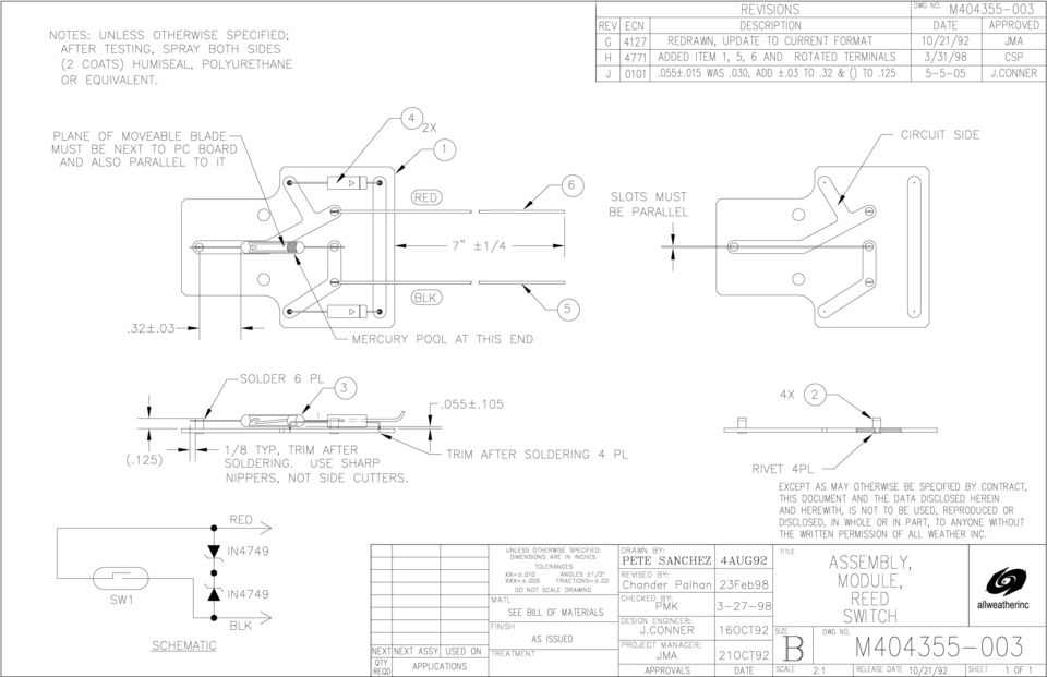
3 1 General Information 1.1 Introduction The Tipping Bucket Rain Gauge is a precision sensor used to measure rainfall volume and/or rate. Rain enters the gauge through a machined orifice and fills one of two buckets located inside the gauge. Each tip of the bucket represents 0.01 inches (0.25 mm) of rainfall with the Model 6011-A, while Model 6011-B accommodates 0.1 mm of rainfall per tip. As the bucket tips, a reed switch makes a momentary closure, registering the tip. Corrosion-resistant materials are used in construction of this instrument, and all external openings are protected from insects and foreign material by mesh screens. 1

4 2 Installation 2.1 General This instrument is thoroughly tested and fully calibrated at the factory and is ready for installation. 2.2 Siting Two prime considerations must be evaluated when locating an installation site for this rain gauge. The gauge must be mounted level and the gauge must be adequately protected from high winds. Errors of more than 5% can occur if not protected from the wind, due to rainfall blowing over the lip of the orifice. Consider the height of surrounding obstacles. Install the rain gauge at a distance away from the obstacles two to four times the obstacle s height. Although the obstacle makes an ideal wind shield, it may block the normal rainfall path into the gauge or rainfall may blow off the obstacle and into the gauge. 2.3 Standard Installation The rain gauge is normally mounted to a poured concrete pad with embedded mounting bolts. To mount the rain gauge to a pad: Pour a 2 ft. x 2 ft. level concrete foundation about 4 inches deep. Embed three 1/4" or 3/8" diameter bolts so that they protrude outward from the foundation, spaced to fit the three feet on the gauge. If strong winds are common at the site, the model 6410 Wind Screen is recommended. Mount the wind screen as described in its accompanying manual. Remove the collection funnel and check the bubble level on the base assembly before bolting the gauge to the foundation or tower mount. If the bubble is not centered, add washers between the base and the base assembly s feet in such a way that the bubble is centered exactly when the bolts are tightened. This is of critical importance to the accuracy of the gauge. Connect the input of the recording device to the two binding posts that terminate the reed switch. Replace the collection funnel and secure the two side screws. 2.4 AWOS Installation Rain gauges used at AWOS installations can be mounted to a pad or to the sensor tower AWOS Pad Installation To mount the sensor to a pad, construct the pad using a Ready-Form tube, rebar, and foundation bolts as shown in Figure 2-1, then proceed as follows: Remove the collection funnel and check the bubble level on the base assembly before bolting the gauge to the foundation or tower mount. If the bubble is not centered, add washers between the base and the base assembly s feet in such a way that the bubble is centered exactly when the bolts are tightened. This is of critical importance to the accuracy of the gauge. Connect the input of the recording device to the two binding posts that terminate the reed switch. Replace the collection funnel and secure the two side screws. 2

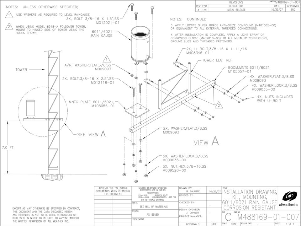
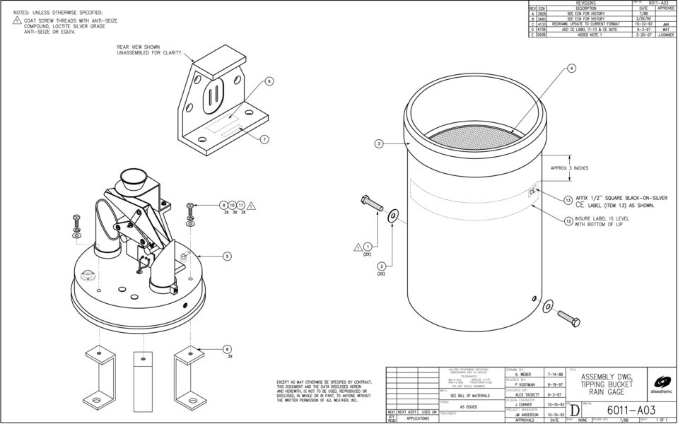
5 MODEL 6011 TIPPING BUCKET RAIN GAUGE (Figure 2-1) AWOS rain gauge pad construction AWOS Tower Installation 2.5 Connection Using the M tower mounting kit, the sensor mounts to a horizontal boom attached to the tower approximately 7' above the ground. To mount the rain gauge to a tower, refer to Drawing No. M at the back of this manual, then proceed as follows: Remove the collection funnel and check the bubble level on the base assembly before bolting the gauge to the foundation or tower mount. If the bubble is not Connect a two-conductor cable between the two terminal posts on the gauge and the event accumulating device. Be sure to remove any packing material and the bucket retaining clips from the instrument. centered, add washers between the base and the base assembly s feet in such a way that the bubble is centered exactly when the bolts are tightened. This is of critical importance to the accuracy of the gauge. Connect the input of the recording device to the two binding posts that terminate the reed switch. Replace the collection funnel and secure the two side screws. Verify correct calibration before reinstalling the outer housing. 3

6 3 Theory of Operation 3.1 Operation The rain gauge s eight inch diameter orifice was chosen as a compromise between two conflicting elements the increased accuracy of a large sampling area, and the practical benefits of a small tipping bucket mechanism. Precipitation is collected by the large funnel at the gauge orifice, which helps prevent evaporation inside the instrument. The collected precipitation is then channeled to the small funnel inside the instrument and directed to one of two tipping buckets. When one bucket fills, its weight tips the next bucket into position and the first empties. At the same time, a 100 millisecond momentary contact closure increments an event accumulating device. The measured water is drained out the bottom of the instrument. A tank can be designed, if needed, to catch the water draining out of the instrument for further evaluation. In AWOS systems, the rain gauge is used to correct visibility measurements when precipitation is present. When precipitation is falling, visibility measurements register a value less than the actual visibility. The degree to which the visibility value is affected depends on the intensity of the precipitation. To correct for this, the AWOS interprets the rain gauge data and corrects the visibility value with one of several correction factors corresponding to the intensity of the precipitation. 4

7 4 Calibration 4.1 Calibration Requirements This instrument was calibrated before leaving the factory and should not require any further calibration unless maintenance is performed on the instrument. For Model 6011-A, milliliters of water is equivalent to 0.01" of rainfall and milliliters of water is equivalent to 0.25 mm of rainfall. For Model 6011-B, milliliters of water equals 0.1 mm of rainfall. 4.2 Calibration To calibrate the tipping bucket rain gauge, follow the steps below: Remove the two screws at the base of the gauge and remove the outer cover. Be sure the gauge remains level. Use the built-in bull s eye level as an indicator. Devise a water source with a uniform flow rate of approximately 400 milliliters per hour. Direct this flow onto the wall of the small funnel. Set up a counting device, such as an event recorder or solenoid counter, to count the number of tips of the bucket assembly, or count the tips yourself. After the gauge has tipped several times and the buckets are wet, collect the water in two containers (one beneath each drain tube). Carefully insert the collection containers between tips and allow at least 10 tips of each bucket (20 counts on the recorder). Remove the containers between tips after an even number of tips. Measure the amount of water in each container by weight or volume. Divide each quantity by the number of tips of each bucket. The value should be within 0.5% of the value listed in Figure Adjustment Adjustments may be made to the stops located under the buckets. Raising the stop of the bucket will reduce the catch for that bucket; conversely, lowering the stop will increase the catch. NOTE: The stop for a bucket is located under the opposite bucket. Make adjustments in small steps (1/4 turn per test). Repeat the calibration procedure until the gauge is within specifications. The above procedure is for a rate of 0.5" per hour. The gauge may be calibrated at any selected rate. After calibration, note the date and place of calibration and reinstall the outer cover and three screws. Be sure the cover is lined up correctly. If the gauge has been removed from a field location for calibration, be sure to level it properly following installation. 5

8 MODEL 6011 TIPPING BUCKET RAIN GAUGE 4.4 Field Checks To check for calibration in the field, make sure the buckets are empty and add the amount of water specified in Figure 4.1. If the buckets tip too soon or do not tip at all, the instrument requires a laboratory calibration as previously described. A standard 10 milliliters pipette or a Model Calibrator can be used as a field test device. For maximum sensitivity, remove both the outer cover and the small funnel. Direct the water toward the center of the bucket partition when the buckets are at midpoint. The errors introduced by surface wetting and droplet formation at the funnel tip are eliminated using this method of calibration. For Model 6011-A:.01 in. of rain = cc per tip.25 mm of rain = cc per tip For Models 6011-B:.1 mm of rain = cc per tip Use the following equation to calculate cc per tip: cc per tip = pr 2 x depth of rain per tip Example: For.01 in. of rain per tip cc per tip = pr 2 x 0.01 in. where r = in. cc per tip = in. 2 x.01 in. cc per tip = in in. 3 = cc (1 in. = 2.54 cm) (Figure 4-1) Calculating water volume per bucket tip. 6

9 MODEL 6011 TIPPING BUCKET RAIN GAUGE The Model Precipitation Gauge Calibrator simplifies field checks of tipping bucket rain gauges by regulating the flow of water into the gauge during calibration. The calibrator consists of a plastic water bottle, a stand for holding the bottle and directing the flow into the funnel, and an orifice. During calibration, a measured amount of water equal to 100 tips of the bucket assembly is directed into the gauge at a constant rate of 2 inches per hour. A laboratory balance should be used to measure the water. If the counter attached to the gauge records more or less than 100 tips, recalibration of the gauge should be considered. This calibration method provides the greatest accuracy and repeatability since measurement is based on an average over 100 tips. The rugged nature of the calibrator also makes it more practical than fragile pipettes or graduated cylinders for field use. (Figure 4-2) Model Rain Gauge Calibrator 7

10 5 Maintenance 5.1 General Normal maintenance is limited to cleaning debris out of the orifice. When the sensor is installed as part of an AWOS system, special maintenance procedures are required. Refer to the following section for details. 5.2 AWOS Periodic Maintenance Periodic maintenance of AWOS sensors is divided into three categories: monthly maintenance, quarterly maintenance, and annual maintenance. The listed maintenance routines are performed according to that schedule Tools and Equipment Required Monthly Maintenance The following tools and equipment are required for performing periodic AWOS maintenance: 1/4" wrench Remove the screen from the funnel of the rain gauge and gently tap the screen to free any dirt or debris. Replace the screen Quarterly Maintenance Quarterly maintenance of the Model 6011 is identical to the monthly maintenance procedure: Remove the screen from the funnel of the rain gauge and gently tap the screen to free any dirt or debris. Replace the screen Annual Maintenance During annual maintenance, perform the following procedures in addition to those outlined for monthly and quarterly maintenance. 1 The output of the rain gauge is a switch closure, each closure being equivalent to a known volume of collected rainfall (0.01"). The funnel, screen, and buckets shall be cleared of debris before this procedure as described in the monthly tasks. 2 Remove the outer cover by removing two 1/4" bolts. Check for sensor level using the bubble level provided on the base. Adjust if necessary. 3 Inspect the interior of the gage for physical lightning damage. 4 Note the precipitation quantity on the DCP's LCD display. Toggle the bucket assembly one cycle (2 tips). Again read the precipitation quantity on the LCD display. It must be 2 counts greater than before. 5 Replace the outer cover, bolts, and screen. 8

11 6 Warranty 6.1 Standard Warranty Unless specified otherwise, All Weather Inc. (the Company) warrants its products to be free from defects in material and workmanship under normal use and service for one year from date of shipment, subject to the following conditions: a. The obligation of the Company under this warranty is limited to repairing or replacing items or parts which have been returned to the Company and which upon examination are disclosed, to the Company s satisfaction, to have been defective in material or workmanship at time of manufacture. b. The claimant shall pay the cost of shipping any part or instrument to the Company. If the Company determines the part to be defective in material or workmanship, the Company shall prepay the cost of shipping the repaired instrument to the claimant. Under no circumstances will the Company reimburse claimant for cost incurred in removing and/or reinstalling replacement parts. c. This warranty shall not apply to any Company products which have been subjected to misuse, negligence, or accident. d. This warranty and the Company's obligation thereunder is in lieu of all other warranties, express or implied, including warranties of merchantability and fitness for a particular purpose, consequential damages, and all other obligations or liabilities. No other person or organization is authorized to give any other warranty or to assume any additional obligation on the Company's behalf, unless made in writing and signed by an authorized officer of the Company. 6.2 AWOS Warranty This equipment has been manufactured and will perform in accordance with requirements of FAA Advisory Circular 150/ B. Any defect in design, materials, or workmanship which may occur during proper and normal use during a period of 1 year from date of installation or a maximum of 2 years from shipment will be corrected by repair or replacement by All Weather Inc. 9

12 7 Specifications Type Tipping Bucket Sensitivity 6011-A 0.01" (0.25 mm) 6011-B.1 mm Resolution 6011-A 0.01" (0.25 mm) 6011-B.1 mm Orifice opening 8" dia. (20 cm) Calibrated accuracy ±0.5% at 0.5"/hr. Repeatability ±3% Insect protection Mesh screens Capacity Unlimited Output 100 ms switch closure Switch type Form A reed Size 8" dia. x 18" H (203 mm dia. x 457 mm H) Weight/Shipping 8 1bs./15 lbs. (3.6 kg/6.8 kg) 10
 Weight/Shipping 8 1bs./15 lbs. (3.6 kg/6.")
13 8 Drawings 8.1 Contents The following pages include reference drawings to aid in maintenance and use of this instrument. 11

14
15
16

17

18

19

20
21 All Weather Inc National Drive Sacramento, CA Fax: Phone: Toll Free: A-001 Rev. L ECO 1454 March, 2008
Global Water Instrumentation, Inc.
 Global Water Instrumentation, Inc. 11390 Amalgam Way Gold River, CA 95670 T: 800-876-1172 Int l: (916) 638-3429, F: (916) 638-3270 6 Tipping Bucket: RG200 02/05/10 01-343 - 1 - Congratulations on your
Data-Logging Rain Gauge PRODUCT MANUAL
 Data-Logging Rain Gauge PRODUCT MANUAL Item # 3554WD1 Thank you for purchasing a Spectrum Datalogging Rain Gauge. With proper installation and care, it will give you years of accurate and reliable measurements.
USER MANUAL. Rain Collector. with Mountable Base. Product numbers 7857 and 7857M
 USER MANUAL Rain Collector with Mountable Base Product numbers 7857 and 7857M R Davis Instruments, 3465 Diablo Avenue, Hayward, CA 94545-2778 U.S.A. 510-732-9229 www.davisnet.com Rain Collector (#7857
674 Rain Gauge. Installation and Operation Guide
 Installation and Operation Guide Part #60-3283-011 Copyright 1992, 2004. All rights reserved, Teledyne Isco, Inc. Revision J, April 18, 2011 Foreword This instruction manual is designed to help you gain
Retractable Screen. Replacement Screen Instructions
 Retractable Screen Patent Pending Replacement Screen Instructions For RTS, RET, & RTM Products ATTENTION! Retractable screens are not intended to provide security or provide for the retention of objects,
product manual 08.09 H-4210A PORTABLE STATIC CONE PENETROMETER
 08.09 product manual H-4210A PORTABLE STATIC CONE PENETROMETER PORTABLE STATIC CONE PENETROMETER GENERAL INFORMATION The H-4210A Static Cone Penetrometer is an unparalleled device for measuring soil consistency.
Installation Instructions
 7.3L & 6.0L 5/8 FUEL TANK PICKUP KIT Fits 94-07 7.3L & 6.0L Powerstroke Diesel Trucks & Excursions Installation Instructions These instructions are intended simply to be a guide for the installation of
Unpacking, Installation, and Customization
 Unpacking, Installation, and Customization NetShelter WX Enclosure AR100 AR100HD Contents Unpacking... 1 How to Unpack the Enclosure............................... 1 Please Recycle..........................................
Global Water Instrumentation, Inc.
 Global Water Instrumentation, Inc. 11390 Amalgam Way Gold River, CA 95670 T: 800-876-1172 Int l: (916) 638-3429, F: (916) 638-3270 Solar Panels 2 Watt Solar Panel: SP101 5 Watt Solar Panel: SP102 01-752
Architect/Contractor Information Package
 Architect/Contractor Information Package 3M SelfCheck System C-Series C1 Model 877 This package provides architects and contractors with the information necessary for the successful installation of the
Installation and Operating Instructions Installation Instructions for SS EPE-316L Series
 INSTR3010 0406 Installation and Operating Instructions Installation Instructions for SS EPE-316L Series Congratulations on your purchase of this Aqua-Pure high flow, single housing filtration system. This
MODEL G300 BRAKE BLEEDER
 MODEL G300 BRAKE BLEEDER Installation, Operation & Repair Parts Information Branick Industries, Inc. 4245 Main Avenue P.O. Box 1937 Fargo, North Dakota 58103 REV060616 P/N: 81-0035G 1 THIS PAGE INTENTIONALLY
Toroidal Conductivity Sensor
 Instruction Sheet PN 51A-/rev.C June 2012 Toroidal Conductivity Sensor For additional information, please visit our website at www.emersonprocess.com/rosemountanalytical.com SPECIFICATIONS Wetted Materials:
Triple Threat 3-in-1 Game Table 3 IN 1 GAME TABLE
 NG0M Triple Threat 3-in- Game Table 3 IN GAME TABLE Thank 3 in Y Game Table Thank you for your purchase of our product. We work around the clock and around the globe to ensure that our products maintain
Mounting Tripod Kit Installation Manual
 Mounting Tripod Kit Installation Manual For use with Davis s wireless and cabled Vantage Pro2 weather stations, the Mounting Tripod simplifies installation. The tripod supports the Integrated Sensor Suite
MEDIUM FLAT PANEL DISPLAY STATIC MOUNT MSR Series
 INSTALLATION INSTRUCTIONS MEDIUM FLAT PANEL DISPLAY STATIC MOUNT The static mount accommodates medium flat panel displays weighing up to 125 lbs (57 kgs). The teardrop holes in the mount allow for quick
WINEGARD MOTORIZED SENSAR ANTENNA Models MA1055W & MA1055G MADE IN U.S.A. U.S. Patents D500,496 and 7,358,909 INSTALLATION MANUAL
 WINEGARD MOTORIZED SENSAR ANTENNA Models MA1055W & MA1055G MADE IN U.S.A. U.S. Patents D500,496 and 7,358,909 INSTALLATION MANUAL CAUTION: This system is not for use with antenna in raised position while
cbperformance.com Please read this entire brochure prior to installing your CB Performance Products MAGNASPARK II distributor.
 - Easy -wire installation with no external spark box necessary, but can be used with one. - Precision CNC machining and hand assembled construction. This is a premium product. - Accurate super hot spark
DICKSON PW4 DICKSON. Pressure Chart Recorders. Applications & Specifications. Product. Getting Started, Charts & Accessories.
 PW4 Pressure Chart Recorders Contents: Applications and Useful Features Operating Instructions / Getting Started Calibrations Troubleshooting Warranty / Factory Service & Applications The PW4 Weather Resistant
ATS Overhead Table Shelf System INSTRUCTION MANUAL
 ATS Overhead Table Shelf System INSTRUCTION MANUAL ATS Overhead Table Shelf System Instruction Manual Warranty Newport Corporation warrants this product to be free of defects in material and workmanship
Installation and Operation Manual. Digital Remote Meter for Monitoring System Performance. Version: RM-1
 REMOTE METER TM Installation and Operation Manual. Digital Remote Meter for Monitoring System Performance. Version: RM-1 1098 Washington Crossing Road Washington Crossing, PA 18977 USA www.morningstarcorp.com
Part I - Installation
 400 Series Pressure and Differential Pressure Switches Types: H400, H402, H403, H400K, H402K, J400, J402, J403, J400K, J402K UNITED ELECTRIC CONTROLS Installation and Maintenance Instructions Please read
Installation Instructions: (Part # SB76880) XRC Armor Front Fender Kit
 XRC Armor Front Fender Kit") WARNING: Check with Local and State laws before installing this accessory! NOTE: Carefully read entire instructions thoroughly before attempting to install this part. Parts Included: Qty Parts Included:
WARNING: Check with Local and State laws before installing this accessory! NOTE: Carefully read entire instructions thoroughly before attempting to install this part. Parts Included: Qty Parts Included:
A70-R Rainfall Transmitter Instruction Manual Document # 1142H
 A70-R Rainfall Transmitter Instruction Manual Document # 1142H 1 Figure 1 Ramp Mode Output Signal Figure 2 Rain Detector Mode Output Signal 20 20 Loop Current ma 16 12 8 16 Loop 12 Current ma 8 4 Total
ETL listed for installations within 5 ft. (1.5M) of outer edge of water www.srsmith.com 79-15152-00 Rev E2 9.14 Page 1 of 10
 of outer edge of water www.srsmith.com 79-15152-00 Rev E2 9.14 Page 1 of 10") Color Light Streams Large Laminar Installation Manual (CLSLL) Input Power: Total Power: 12V AC 5W 4008814 ETL listed for installations within 5 ft. (1.5M) of outer edge of water 79-15152-00 Rev E2 9.14
Color Light Streams Large Laminar Installation Manual (CLSLL) Input Power: Total Power: 12V AC 5W 4008814 ETL listed for installations within 5 ft. (1.5M) of outer edge of water 79-15152-00 Rev E2 9.14
AUTOMATIC SWINGING DOOR
 A Member of AAADM American Association of Automatic Door Manufacturers AUTOMATIC SWINGING DOOR OWNER'S MANUAL Distributed by: Contents Section Page Caution 2 To Our Customers 2 Service Availability 2 Compliance
Table of Contents WARNING SYMBOLS AND DEFINITIONS
 Table of Contents SAFETY INSTALLATION OPERATION MAINTENANCE Safety... 2 Specifications... 4 Installation... 5 Operation... 8 WARNING SYMBOLS AND DEFINITIONS Maintenance... 9 Parts List and Assembly Diagram...
Global Water Instrumentation, Inc.
 Global Water Instrumentation, Inc. 11390 Amalgam Way Gold River, CA 95670 T: 800-876-1172 Int l: (916) 638-3429, F: (916) 638-3270 Water Level Sensor: WL400 00-997 11/30/09-1 - Congratulations on your
Structural Holding System
 Structural Holding System Users Manual November 2013 by Vehicle Service Group. All rights reserved. CO8812.1 502071 Rev. - 11/21/2013 CHIEF'S LIMITED ONE-YEAR WARRANTY & LIABILITY Chief Automotive Technologies
LIFT N RACK PRO OPERATING & INSTALLATION GUIDE 5500 Lb. LIFT CAPACITY
 LIFT N RACK PRO OPERATING & INSTALLATION GUIDE 5500 Lb. LIFT CAPACITY IMPORTANT: READ THIS MANUAL BEFORE IN-STALLING, OPERATING OR MAINTAINING YOUR LIFT. Chassis Liner Company Sales Office Toll Free: 800-242-2448
TWIN EAGLES ALL WEATHER ELECTRIC RADIANT HEATER
 TWIN EAGLES, INC. Defining the Art of Outdoor Cooking TWIN EAGLES ALL WEATHER ELECTRIC RADIANT HEATER OWNER S MANUAL MODEL TEEH-1512 TEEH-2524 TEEH-3524 NEED ASSISTANCE? PLEASE CALL: (562) 802-3488 This
Articulating TV Wall Mount for 19" to 70" Flat Panel TVs
 THIS INSTRUCTION BOOKLET CONTINS IMPORTNT SETY INORMTION. PLESE RED ND KEEP OR UTURE REERENCE. Lot Number: Date: rticulating TV Wall Mount for 19" to 7" lat Panel TVs Model No: DCD1319 Option 1 Option
Wanda Technology Inc. Side Post Aluminum Umbrella OWNER S MANUAL
 Wanda Technology Inc. Side Post Aluminum Umbrella Portofino II Series OWNER S MANUAL US Patents: 6,439,249 ; 6,692,135 ; 6,598,990 ; 6,966,667 6,945,263 ; 6,923,194 ; 6,830,058 ; 6,565,060 6,511,033 ;
TABLE OF CONTENTS 11.0 WARRANTY
 11.0 WARRANTY OI-1009.205L TABLE OF CONTENTS ELECTROMATIC Equipment Co., Inc. (ELECTROMATIC) warrants to the original purchaser that this product is of merchantable quality and confirms in kind and quality
1000 Series Data Loggers PRODUCT MANUAL
 1000 Series Data Loggers PRODUCT MANUAL Model s 1650, 1525, 1450, 1425, 1400, 1250, 1225, 1200 CONTENTS General Overview 3 Model Specifications 4 External Sensors 5 Installation and Placement 6 Digital
GreenWay Solar LED Path and Trail Lighting System. Installation and Owner s Manual
 GreenWay Solar LED Path and Trail Lighting System Installation and Owner s Manual Important Notes and Warnings This installation and instruction manual provides installation, operation, and maintenance
Auto-belay Cable Replacement Process
 Auto-belay Cable Replacement Process Version 2.00 WARNING: The air pressure in the auto-belay system is what causes the cable to be retracted when releasing the cable or climbing the wall with the cable
Owner s Manual & Safety Instructions
 Owner s Manual & Safety Instructions Save This Manual Keep this manual for the safety warnings and precautions, assembly, operating, inspection, maintenance and cleaning procedures. Write the product s
FLEX by 3M Light Module System
 FLEX by M Light Module System Application FLEX by M (the Product ) is a modular lighting system for dry, interior use (the Application ). The Product allows easy creation of long, D lighting paths along
DUST COLLECTOR 70 GALLON, 2 HP
 DUST COLLECTOR 70 GALLON, 2 HP Model 45378 ASSEMBLY AND OPERATING INSTRUCTIONS 3491 Mission Oaks Blvd., Camarillo, CA 93011 Visit our Web site at http://www.harborfreight.com Copyright 2001 by Harbor Freight
123 Industrial Loop Road Paynesville, MN 56362 Phone: 1-800-864-1649 www.master-mfg.com MASTER MANUFACTURING MASTER GARDNER
 123 Industrial Loop Road Paynesville, MN 56362 Phone: 1-800-864-1649 www.master-mfg.com MASTER MANUFACTURING MASTER GARDNER Part Number PCD E3 009B MM Rev 1 Nov. 2010 INTRODUCTION The purpose of this manual
Propane Conversion Kit PROPANE CONVERSION KIT INSTALLATION MANUAL
 Propane Conversion Kit Supersedes: 145.25-IOM2 (708) Form 145.25-IOM2 (908) PROPANE CONVERSION KIT INSTALLATION MANUAL "LPKIT " - PROPANE CONVERSION KIT Kits are available for field conversion from natural
Owner s Manual & Safety Instructions
 Owner s Manual & Safety Instructions Save This Manual Keep this manual for the safety warnings and precautions, assembly, operating, inspection, maintenance and cleaning procedures. Write the product s
TITAN Fuel Tanks. INSTALLATION INSTRUCTIONS G e n e r a t i o n V
 TITAN pt. no.: 02 0000 0143 Important: Please read these instructions carefully and completely before starting the installation. TITAN Fuel Tanks INSTALLATION INSTRUCTIONS G e n e r a t i o n V Extended
RGC-IR Remote Gas Calibrator for IR400
 Remote Gas Calibrator for IR400 The information and technical data disclosed in this document may be used and disseminated only for the purposes and to the extent specifically authorized in writing by
Operation and Installation Manual
 Operation and Installation Manual RCM-10 Remote Control Monitor and RSM-10 Remote Status Monitor for the CNA-100 & CNA-200 Automations Revision 1.1 9/98 WARRANTY INFORMATION The RCM-10 Remote Control
INSTALLATION AND OPERATION MANUAL
 INSTALLATION AND OPERATION MANUAL USB 2.0 Cat-5 ANTENNA www.libertysafe.com (800) 247-5625 2014 Liberty Safe & Security Products, Inc. PN 11015-001 POWER OUTLET KIT PARTS HUB A COVER PLATE & COVER PLATE
DTM04 TANK MONITOR DTM08 TANK MONITOR Dtm12 TANK MONITOR. Installation and Operation Manual
 DTM04 TANK MONITOR DTM08 TANK MONITOR Dtm12 TANK MONITOR Installation and Operation Manual 1 ENGLISH Safety Instructions 2 Features 2-3 Specifications 3 Installation 4-5 Wiring Diagrams 6-7 Warranty 8
RI-215A Operator s Manual. Part Number: 71-0045RK Revision 0 Released: 10/3/05
 RI-215A Operator s Manual Part Number: 71-0045RK Revision 0 Released: 10/3/05 Warranty RKI Instruments, Inc., warrants gas alarm equipment sold by us to be free from defects in materials and workmanship,
Sealant. 30" Model No. 35020. D: 17-7/8" TO 18-3/8" (454 to 466mm) W: 29-3/4" TO 30-1/4" (756 to 768mm) Under Countertop Installation
 W: 29-3/4 TO 30-1/4 (756 to 768mm) Under Countertop Installation") INSTALLATION INSTRUCTIONS CARE AND MAINTENANCE London Kitchen Sinks 24" Sink model number 35030 30" Sink model number 35020 36" Sink model number 35040 Thank you for selecting Porcher. To ensure this product
INSTALLATION INSTRUCTIONS CARE AND MAINTENANCE London Kitchen Sinks 24" Sink model number 35030 30" Sink model number 35020 36" Sink model number 35040 Thank you for selecting Porcher. To ensure this product
ECM-D70T / ECM-D70T1.5
 Elliptical Ceiling Dual Mount for 37 to 50 Flat Panels INSTALLATION INSTRUCTIONS CREATING POSITIVE CUSTOMER EXPERIENCES 9531-041-001-01 Contents ECM-D70T / ECM-D70T1.5 Installation Tools... 3 Parts List...
Installation Instructions
 PUSH Installation Instructions A DA C O M PLIA NT shown with optional Bradley 90-75 faucet Front-Mounted Barrier Free Rectangular Bowl Stainless Steel Lav Table of Contents Pre-Installation Information...........2
In-Ground Basketball System Owners Manual
 In-Ground Basketball System Owners Manual Customer Service Center N53 W4700 South Corporate Circle Sussex, WI 53089 U.S.A. Write Model Number From Box Here: WARNING! 3 Capable Adults REQUIRED TOOLS AND
ANTENNA SYSTEMS. 1.8m Offset TxRx Antenna INSTALLATION & ASSEMBLY INSTRUCTIONS
 ANTENNA SYSTEMS 1.8m Offset TxRx Antenna INSTALLATION & ASSEMBLY INSTRUCTIONS LIMITED TWELVE (12) MONTH WARRANTY This PATRIOT ANTENNA equipment is warranted to be free from defects in material and workmanship
Flat Bottom Long Ram Hydraulic Jack
 Flat Bottom Long Ram Hydraulic Jack 3 Ton 8 Ton 36468 36469 ASSEMBLY & OPERATING INSTRUCTIONS 349 Mission Oaks Blvd., Camarillo, CA 930 Visit our Web site at http://www.harborfreight.com TO PREVENT SERIOUS
Bottom Loading Water Dispenser
 Bottom Loading Water Dispenser Model # 601000 TO REDUCE THE RISK OF INJURY AND PROPERTY DAMAGE, USER MUST READ THIS MANUAL BEFORE ASSEMBLING, INSTALLING & OPERATING DISPENSER. SAVE THIS MANUAL FOR FUTURE
KEEP FOR FUTURE REFERENCE MRTALP VERTICAL LIFT BAR READ ALL INSTRUCTIONS AND WARNINGS BEFORE USING THIS PRODUCT
 KEEP FOR FUTURE REFERENCE INSTRUCTIONS P.O. Box 368 908 West Main Laurel, MT USA 59044 phone 800-548-7341 phone 406-628-8231 fax 406-628-8354 International Version MODEL NUMBER: LB10VLB MRTALP VERTICAL
SE-100-1, SE-200-1, SE-500-1, and SE-1000-1 AIR CHAMP PRODUCTS. User Manual SE BRAKE MODELS: (i) MTY (81) 83 54 10 18 ventas@industrialmagza.
 MTY (81) 83 54 10 18 ventas@industrialmagza.") AIR CHAMP PRODUCTS User Manual SE BRAKE MODELS: SE-00-, SE-200-, SE-500-, and SE-000- (i) FORM NO. L-20084-E-040 In accordance with Nexen s established policy of constant product improvement, the specifications
AIR CHAMP PRODUCTS User Manual SE BRAKE MODELS: SE-00-, SE-200-, SE-500-, and SE-000- (i) FORM NO. L-20084-E-040 In accordance with Nexen s established policy of constant product improvement, the specifications
RZ Guardrail System Installation Manual
 TM RZ Guardrail System Installation Manual RZ Guardrail System Compliance is based on OSHA standards: (Standards - 29 CFR) 1910.23 (e) and (Standards - 29 CFR) 1926.502 (b) Failure to read, understand
LCD5500Z / PKP-LCD v3.x Installation Instructions
 LCD5500Z / PKP-LCD v3.x Installation Instructions TM Introduction The LCD5500Z / PKP-LCD keypad displays system status using an LCD screen. The keypad can be used on PowerSeries security systems with up
SCREAMIN' EAGLE "HEAVY BREATHER" PERFORMANCE AIR CLEANER KIT
 REV. 05-04- SCREAMIN' EAGLE "HEAVY BREATHER" PERFORMANCE AIR CLEANER KIT GENERAL Kit Numbers 95-08B, 9006-09B, 876-0A Models For model fitment information, see the P&A Retail Catalog or the Parts and Accessories
Micron-Master EL Series Fogger
 Micron-Master EL Series Fogger Instruction Manual Please read and keep these instructions For Models: EL2 Wall Mount EL3 Wall Mount EL4 Wall Mount EL2 Cart Mount EL3 Cart Mount EL4 Cart Mount EL3 Generator
Part Name/Description Part Number Quantity. Power Cable 4000950-5 1
 Note: Indented items indicate parts included in an assembly listed above Part Name/Description Part Number Quantity Power Cable 4000950-5 1 Raven Harness Adapter Kit 4100525 1 Installation Instructions
Owner s Manual Read and keep this manual. Patents World Wide
 Owner s Manual Read and keep this manual. Patents World Wide S & S Industries, Inc., Sarasota, FL, USA www.trail-gator.com Copyright 2008 All Rights Reserved The following manual is provided to assist
Important: Please read these instructions carefully and completely before starting the installation. TITAN Fuel Tanks
 TITAN pt. no.: 03 0000 0120 Important: Please read these instructions carefully and completely before starting the installation. TITAN Fuel Tanks INSTALLATION INSTRUCTIONS G e n e r a t i o n V Extended
Fiberstars Lighted Laminar Flow Fountain Installation Manual
 Fiberstars Lighted Laminar Flow Fountain Installation Manual 79-15037-00 REV Xx http://www.fiberstars.com Page 1 of 8 SAVE THESE DIRECTIONS! These directions are provided to ensure the proper installation
PATHWAY Classic Series with Handrails Portable Wheelchair Ramp INSTRUCTIONS FOR USE 6428 REV A 05-21-09
 PATHWAY Classic Series with Handrails Portable Wheelchair Ramp INSTRUCTIONS FOR USE. INSTRUCTIONS 1) FOR EZ-ACCESS PATHWAY RAMP WITH HANDRAILS 850 pound weight capacity. Available in 4, 6, 8 & 10 lengths.
Rebuild Instructions for 70001 and 70010 Transmission
 Rebuild Instructions for 70001 and 70010 Transmission Brinn, Incorporated 1615 Tech Drive Bay City, MI 48706 Telephone 989.686.8920 Fax 989.686.6520 www.brinninc.com Notice Read all instructions before
UNIVERSAL LUMBAR INSTALLATION INSTRUCTIONS
 UNIVERSAL LUMBAR INSTALLATION INSTRUCTIONS CONTENTS Parts List... 2 Parts Diagram... 2 Helpful Hints... 3 Installation... 4 Operation and Troubleshooting Guide... 6 Warranty Information... 8 Form #3132,
Installation Instructions 4508 4508S
 SYMPHONY Spread Lavatory Faucet with Speed Connect Drain Congratulations on purchasing your American Standard faucet with Speed Connect drain, a feature found only on American Standard faucets. Speed Connect
Elo Touch Solutions Wall-mounting Kit for the 5501L IDS Touchmonitors
 Installation Manual Elo Touch Solutions Wall-mounting Kit for the 5501L IDS Touchmonitors SW602206 Rev B Table of Contents Chapter 1: Safety Warning... 3 Chapter 2: Kit Contents... 4 Included in Kit...
AUTOMATIC SWINGING DOOR
 AAADM American Association of Automatic Door Manufacturers AUTOMATIC SWINGING DOOR OWNER'S MANUAL Distributed by: Section Contents Page Caution 2 To Our Customers 3 Service Availability 3 Compliance with
STAGE SETTER-8. User Instructions. Elation Professional
 STAGE SETTER-8 User Instructions Elation Professional A Division of the American DJ Group of Companies 4295 Charter Street Los Angeles, CA 90058 USA Tel: 323-582-2650 Fax: 323-582-2610 Web: www.elationlighting.com
Instruction Manual HI 96800 Refractometer for Refractive Index and Brix Measurements
 Instruction Manual HI 96800 Refractometer for Refractive Index and Brix Measurements www.hannainst.com 1 Dear Customer, Thank you for choosing a Hanna Instruments product. Please read this instruction
Installation Instructions:
 Portable Guardrail System Model Numbers: 7900060, 7900061, 7900062, 7900063 Installation Instructions: Portable Guardrail System This instruction is intended to meet the Manufacturer s Instructions requirement
Precision Miniature Load Cell. Models 8431, 8432 with Overload Protection
 w Technical Product Information Precision Miniature Load Cell with Overload Protection 1. Introduction The load cells in the model 8431 and 8432 series are primarily designed for the measurement of force
Digital Fingerprint safe
 Digital Fingerprint safe Model 96846 Operation Instructions Diagrams within this manual may not be drawn proportionally. Due to continuing improvements, actual product may differ slightly from the product
MSD Pro-Billet Ready-to-Run Chevrolet V8 Distributor, PN 8360 Chevrolet 348, 409 Distributor, PN 8393
 MSD Pro-Billet Ready-to-Run Chevrolet V8 Distributor, PN 8360 Chevrolet 348, 409 Distributor, PN 8393 ONLINE PRODUCT REGISTRATION: Register your MSD product online and you ll be entered in our monthly
Oceanscience Cable Chimp II Cableway ROV System User Guide and Warranty
 Oceanscience Cable Chimp II Cableway ROV System User Guide and Warranty Page 1 Table of Contents Introduction Page 3 Overview Page 3 Setup and Operation Page 5 Remote Control Page 6 Power Management Page
Foodservice Equipment Specialists P.O. Box 880 Saco, ME. / U.S.A. 04072 877-854-8006 * FAX (207) 283-8080
 283-8080") Foodservice Equipment Specialists P.O. Box 880 Saco, ME. / U.S.A. 04072 877-854-8006 * FAX (207) 283-8080 FOR SERVICE ASSISTANCE U.S. AND CANADA CALL: 1-877-854-8006 24 HOURS/DAY 7 DAYS/WEEK TABLE OF CONTENTS
Foodservice Equipment Specialists P.O. Box 880 Saco, ME. / U.S.A. 04072 877-854-8006 * FAX (207) 283-8080 FOR SERVICE ASSISTANCE U.S. AND CANADA CALL: 1-877-854-8006 24 HOURS/DAY 7 DAYS/WEEK TABLE OF CONTENTS
REDI-LINE ELECTRIC GENERATORS USER'S GUIDE. Rugged, Reliable, DC to AC Power Conversion
 REDI-LINE ELECTRIC GENERATORS USER'S GUIDE Rugged, Reliable, DC to AC Power Conversion REDI-LINE ELECTRIC GENERATOR MODEL INPUT ACTUAL OUTPUT ACTUAL OUTPUT WATTS SERIAL NO. PACIFIC SCIENTIFIC MOTOR PRODUCTS
White Industries Rear Hub Instructions
 White Industries Rear Hub Instructions Tool required: 2mm allen/hex wrench, 19mm socket, 20mm socket, and mallet. 1. Loosen the set screws located in the adjusting collar by using a 2mm allen wrench inserted
Wind Direction Smart Sensor (S-WDA-M003)
") (S-WDA-M003) The Wind Direction smart sensor is designed to work with HOBO Stations. The smart sensor has a plug-in modular connector that allows it to be added easily to a HOBO Station. All sensor parameters
(S-WDA-M003) The Wind Direction smart sensor is designed to work with HOBO Stations. The smart sensor has a plug-in modular connector that allows it to be added easily to a HOBO Station. All sensor parameters
Auxiliary Rams USERS MANUAL
 Auxiliary Rams 2007 Chief Automotive Technologies, Inc. Chief s Limited One-Year Warranty & Liability CHIEF'S LIMITED ONE-YEAR WARRANTY & LIABILITY Chief Automotive Technologies, Inc. warrants for one
Installation Instructions
 520 Installation Instructions Thank you very much for purchasing PIAA product. Please read this entire manual before installation and use of this product. For Installers Please give this Installation Manual
C554 Series ADJUSTABLE HEIGHT. Version 3
 C554 Series ADJUSTABLE HEIGHT GOAL SYSTEM Version 3 Thank you and congratulations for purchasing a Ryval Hoops Goal - the finest basketball goal system on the market today! You will discover that Ryval
Wireless Indoor/ Outdoor Thermometer
 Wireless Indoor/ Outdoor Thermometer Owner s Manual Please read before using this equipment. ˆ Contents FCC Information... 3 FCC Declaration of Conformity... 5 Preparation... 5 Installing Batteries...
WS-9005TWC 915MHz WIRELESS RAIN GAUGE INSTRUCTION MANUAL
 WS-9005TWC 915MHz WIRELESS RAIN GAUGE INSTRUCTION MANUAL CONTENTS 03 introduction 03 features 04 setting up 06 function keys 06 operations 07 mounting 08 maintenance 09 specifications 09 liability disclaimer
ALUMINUM UNIVERSAL VAN / CAP RACK INSTRUCTIONS ROOF MOUNT APPLICATION P/N ULRHDGV-1 / ULRHDGC-1
 ALUMINUM UNIVERSAL VAN / CAP RACK INSTRUCTIONS ROOF MOUNT APPLICATION P/N ULRHDGV-1 / ULRHDGC-1 Package Contents: (8) Load Secure Posts (2) Cross Bars (4) Curved Arms (4) G Mount Hinges (4) G Mount Rubber
PNEUMATIC PLANISHING HAMMER
 PNEUMATIC PLANISHING HAMMER 94847 ASSEMBLY AND OPERATING INSTRUCTIONS Due to continuing improvements, actual product may differ slightly from the product described herein. Distributed Exclusively by Harbor
Failure to comply with the following cautions and warnings could cause equipment damage and personal injury.
 1.0 IMPORTANT RECEIVING INSTRUCTIONS Visually inspect all components for shipping damage. Shipping Damage is not covered by warranty. If shipping damage is found, notify carrier at once. The carrier is
Operators Manual SOIL COMPACTION TESTER
 Operators Manual SOIL COMPACTION TESTER ENGLISH DOCU-M0116 03-10 Introduction THANK YOU for purchasing the Soil Compaction Tester. READ THIS MANUAL carefully to learn how to operate and service your Soil
Periodic Verification System Model 775PVS
 Periodic Verification System Model 775PVS Instruction Manual Contents 1 Description... 1 775PVS System... 1 Model 775 Fieldmeter... 2 Model 775C Charger... 2 Model 775P Plate Assembly... 3 2 Operation...
Dog Kennel WORLDWIDE. 1-800-955-2879 E-mail: [email protected]
 Dog Kennel WORLDWIDE 1-800-955-2879 E-mail: [email protected] IMPORTANT NOTICE! PLEASE READ INSTRUCTIONS COMPLETELY PRIOR TO ASSEMBLING YOUR LUCKY DOG EASY SHIP CHAMPION DOG KENNEL. Watch for helpful
Euro Cart. Compact Equipment Cart Made in the USA. Operation Manual Version 1.0 Copyright 2013 Professional Sound Corporation Printed in the U.S.A.
 Euro Cart Compact Equipment Cart Made in the USA Operation Manual Version 1.0 Copyright 2013 Professional Sound Corporation Printed in the U.S.A. Thank you for purchasing the Professional Sound Corporation
VDO ELECTRONIC SPEEDOMETER HALL EFFECT SENDER INSTALLATION INSTRUCTIONS AND WIRING DIAGRAM TYPE A SPEEDOMETER 4-WIRE SYSTEM 5(' %52:1 <(//2: :+,7(
 VDO ELECTRONIC SPEEDOMETER HALL EFFECT SENDER INSTALLATION INSTRUCTIONS AND WIRING DIAGRAM 7UDQVPLVVLRQ TYPE A SPEEDOMETER 4-WIRE SYSTEM Y 6:,7&+(' $&&(6625< %52:1
REPAIR AND MAINTENANCE MANUAL
 REPAIR AND MAINTENANCE MANUAL Professional Pest Control Application Equipment Prime Line Sprayers B&G Equipment Company 135 Region South Drive, Jackson, GA 30233 800.544.8811 Phone 678.688.5601 Fax 678.688.5633
PARTICLE GENERATOR MODEL 8026
 PARTICLE GENERATOR MODEL 8026 OPERATION AND SERVICE MANUAL P/N 1980319, REVISION M MARCH 2016 Copyright TSI Incorporated / Revision M / 2000 2016 / All rights reserved. Address TSI Incorporated / 500
DUSTTRAK AEROSOL MONITOR SOLAR POWER KIT MODEL 854060
 DUSTTRAK AEROSOL MONITOR SOLAR POWER KIT MODEL 854060 (FOR DUSTTRAK II AND DRX AEROSOL MONITOR MODELS 8540 AND 8543) OPERATION AND MAINTENANCE MANUAL P/N 6008416, REVISION A MAY 2015 Copyright TSI Incorporated