Technique and Safety of. by Pierluigi Castellone, Electronics Engineer Brain Products General Manager
|
|
|
- Gertrude Harrington
- 9 years ago
- Views:
Transcription
1 Technique and Safety of performing EEG/fMRI measurements by Pierluigi Castellone, Electronics Engineer Brain Products General Manager

2 Contents of the presentation Why recording simultaneous EEG and fmri? Challenges in recording EEG in the MRI: Safety issues Challenges in recording EEG in the MRI: Technical issues Brain Products solutions and recommendations Four steps to successful EEG/fMRI measurement

3 Why recording EEG? The activation of neurons produces an electrical signal which can be detected by using electrodes placed on the scalp. Being an electrical signal, any change in the neural activation is detected very quickly. The EEG has time resolution in the order of milliseconds but bad spatial resolution (inverse problem not solvable).

4 Why recording fmri? Stimulation of the brain causes a local increase in blood flow. To the increase of oxygen in the activated areas does not correspond an increase of the used oxygen. This results in a net increase of oxygen in the area activated. We can recognize two phases related to the brain activation: (1) Deoxygenated blood (Paramagnetic distortions in the MRI signal) increases due to areas activated. T2 and T1 are shorter. (2) Oxygenated blood (Diamagnetic no distortions in the MRI signal) flows in the activated areas. T2 and T1 are longer. By scanning the brain over time repeatedly, it s possible to detect the BOLD (Blood Oxygenation Level Dependent) signal.
 Oxygenated blood (Diamagnetic no distortions in the MRI signal) flows in the activated areas. T2 and T1 are longer.")
5 Why recording fmri? The fmri can detect local brain activations with an extremely fine spatial resolution (order of millimetres). Nevertheless it has bad temporal resolution (1 sec in the best case).
.")
6 Why recording simultaneously EEG and fmri? Oz [µv] [ms]

7 Why recording simultaneously EEG and fmri? In every cognitive experiment, the EEG/fMRI co-registration offers the unique chance to record the brain activity originated by a specific stimulation under the SAME experimental conditions! The validity of data acquired for the EEG and fmri domains in separate sessions is not only dependent on aspects related to the experimental paradigm, but also depends on differences in the measurement environment. The restricted space available in the scanner bore, the position of the experiment subject during the simultaneous recording (supine rather than sitting upright) and the loud noise caused by the MRI gradient system are all factors altering the experimental effects.

8 Why recording simultaneous EEG and fmri? In every cognitive experiment, the EEG/fMRI co-registration offers the unique chance to record the brain activity originated by a specific stimulation under the SAME experimental conditions! To reduce the costs related to the experiments To reduce the working time

9 Challenges in recording EEG in the fmri: Safety Issues

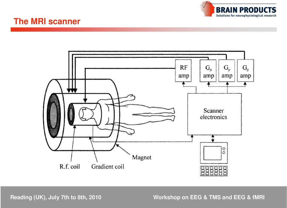
10 The MRI scanner
11 The MRI scanner EPI sequence design

12 Challenges in recording EEG in the MRI: Safety issues (1) Static magnetic field (2) Gradients (3) Radio frequency pulses The strength of the magnetic field of a scanner is measured in units of Tesla. Today, a normal magnet would be a 1.5 or 3T scanner, where 3T means that the magnetic field is roughly x stronger than the earth s natural magnetic field of.00005t! This static magnetic field is ALWAYS on!

13 Challenges in recording EEG in the MRI: Safety issues Complete patient monitoring system wedged in the opening of a 1.5 T MR scanner system It is normally not possible to remove such an object since simple human power and force is insufficient for removal. In most of the cases the scanner has to be quenched, completely shutting off the power and the Helium cooling system. The cost of this is approximately $!

14 Challenges in recording EEG in the MRI: Safety issues Acoustic noise: During MR imaging, the slowly-varying gradient fields are continuously turned on and off at variable rates and cause a loud noise (mechanical resonance). Ear plugs and passive noise reduction are needed. Neural activation: The gradients being switched are so strong that they can lead to peripheral nerve stimulation and peripheral muscle contraction.

15 Challenges in recording EEG in the MRI: Safety issues According to the Faraday s Law, the RF field used in MR imaging induces currents into an electrically conductive object. The induced current also changes its direction continuously. The RF energy emitted during slice acquisition is coupled onto the electrode leads and dissipated at the points of highest thermal resistance, which is typically the contact point between the electrode pin and the scalp across the conductive gel. The RF energy is dissipated also on the first stage of the amplifier.

16 Challenges in recording EEG in the MRI: Safety issues

17 Brain Products solutions and recommendations BrainAmp MR systems are the only commercially available solutions designed to work directly INSIDE the MRI bore: There is no ferrite in the amplifier The system is powered by MRI-compatible batteries The first stage of the amplifier filters out high frequencies potentially very dangerous for the hardware Most of the more sensitive electronics circuitry needed to operate the system are in the control room (USB interface)

18 Brain Products solutions and recommendations The electrical connections from the cap to the amplifier s input stage are shorter and thereby the influence of the MRI gradient switching system on the acquired data is minimized. Furthermore, shorter cables massively reduce the likelihood to spoil the data acquisition with artifacts induced by cable motion and other types of noise in the MRI environment.

19 Brain Products solutions and recommendations The BrainCap MR transmits the electrophysiological signals from the subject s head through a short distance of about 50 cm right into the BrainAmp MR/MR plus which is also placed directly in the scanner. BrainCap MR BrainAmp MR BrainVision professional Recorder Stimulation

20 Brain Products solutions and recommendations BrainCap MR features (1): In the combined EEG/fMRI acquisition the electrodes should never touch the skin. Our electrodes are pin type sensors which are placed inside a plastic holder mounted on the cap. Gel will be filled into the holder to reduce skin conductance and to establish a contact between the sensor and the subject's skin. Every electrode contains safety resistors between the sensor and the connection wire. Connection between the components is performed by gluing, not soldering. Additional safety resistors are placed inside the cap connector, acting like an additional RF-filter. Wires are located at the outside of the cap to ensure isolation between skin and wire according to the FDA patient safety regulations.

21 Brain Products solutions and recommendations BrainCap MR features (2): High temperature isolating tubes wrapped around the ECG electrode cable avoid creating contact between skin and wire. Drop-down electrodes contain higher resistors than normal electrodes to compensate the technical characteristics of longer wires. All wires are fixed onto the cap to avoid loops. Wire length from electrode to the amplifier s input is fixed to a maximum of 1.5m not to match the Larmor frequency. Wire outlets for the cable tree at central positions avoid creating loops due to cable routing.
22 Brain Products solutions and recommendations Picture from Veera Merilainen s thesis Helsinki University of Technology MRI sequence: The picture shows temperature changes induced by three different MR sequences in a frontopolar EEG electrode on a sheep s head. MR scanning was performed for 900 seconds with each sequence.
23 Brain Products solutions and recommendations Strict restriction to low SAR sequences GE-Localizer GE-Structural sequences (MP-RAGE) GE-EPI Whenever the subject wears a EEG cap: No Spin-Echo No Turbo-Spin-Echo No Spiral-EPI Avoid Body-Coil Tx!! Use whenever available head coil TxRx
24 What not to do
25 Otherwise
26 Challenges in recording EEG in the fmri: Technical Issues
27 Challenges in recording EEG in the MRI: Technical issues When an object with the susceptibility* different from that of surrounding tissues is placed in a homogeneous magnetic field, it distorts the field and causes local inhomogeneties. *In physics and electrical engineering, the magnetic susceptibility is the degree of magnetization of a material
28 Challenges in recording EEG in the MRI: Technical issues Two clear artifacts are visible in the EEG during the combined experiment: (1) Gradient artifact (2) Pulse artifact
29 Challenges in recording EEG in the MRI: Technical issues The gradient artefact is caused by the variation over time in the strength and polarity of the electromagnetic field used in MR imaging. Fp1 Fp2 F3 F4 C3 C4 P3 P4 O1 O2 F7 F8 T7 T8 P7 P8 Iz Cz Pz FC1 FC2 CP1 CP2 FC5 FC6 CP5 CP6 TP9 TP10 Eog Ecg 100 µv S 2 S 1 S 2 S 2 S 1 S 3 S 1 S 2 S 3 S 1 S 3
30 Challenges in recording EEG in the MRI: Technical issues If the position of the conductor changes relatively to the magnetic field (motion artifact, ballistocardiogram artifact) Fp1 Fp2 F3 F4 C3 C4 P3 P4 O1 O2 F7 F8 T7 T8 P7 P8 Fz Cz Pz Oz FC1 FC2 CP1 CP2 FC5 FC6 CP5 CP6 TP9 TP10 EOG ECG Scan Start Scan Start Scan Start Scan Start
31 Challenges in recording EEG in the MRI: Technical issues Four steps to successful EEG/fMRI measurement (1) Safe Subject Preparation (2) Trigger Setup / Synchronization (3) Proper Measurement Settings (4) Correct Data Preparation
32 Challenges in recording EEG in the MRI: Technical issues (1) Safe subject preparation Informed consent must be obtained from all subjects! It must be established that the subject does not have any implants that are ferrous or magnetizable. The subject must be free from claustrophobia. The subject has to fully understand the procedure and also any potential causes of harm such as the ambient noise, gradient induced peripheral effects and the difficulty of fast exiting.
33 Challenges in recording EEG in the MRI: Technical issues (2) Trigger Setup Scanner artifacts are technical in nature, meaning that they are always the same from acquisition to acquisition. In order to correct the EEG data for these artifacts we must find the onset of each of these episodes very exactly. This can either be done in software by detecting features or values or it can be done with the help of the scanner system, which can normally issue a trigger at the exact time point of slice or volume acquisition. On BrainAmp MR systems, the normal stimulation system trigger cable is complemented with a BNC trigger input that is internally connected to Bit 15, thus giving a trigger of type Response and with the code R128 for every pulse the scanner sends. Most scanners are set up to send such a pulse with every slice or with every volume onset by default.
34 Challenges in recording EEG in the MRI: Technical issues (2) Synchronization Most scanners provide the service technicians with a diagnostic output that is phase synchronous with the gradient clock itself. This mechanism allows for easy synchronization between the scanner gradient system and the BrainAmp sample clock. The scanner has to provide a signal that is an integer multiple of 5000 Hz, such as 20 khz, 1 MHz, 20 MHz,
35 Challenges in recording EEG in the MRI: Technical issues
36 Challenges in recording EEG in the MRI: Technical issues (3) Proper Measurement Settings The sample rate has to be set to The amplifier bandwidth should be adjusted according to the characteristics of the system used [DC or Hz]. The vertical resolution should be set at 0.5 µv/lsb. Only if it is known that the system has weak and low gradients 0.1µV/LSB should be used.
Functional neuroimaging. Imaging brain function in real time (not just the structure of the brain).
.") Functional neuroimaging Imaging brain function in real time (not just the structure of the brain). The brain is bloody & electric Blood increase in neuronal activity increase in metabolic demand for glucose
Functional neuroimaging Imaging brain function in real time (not just the structure of the brain). The brain is bloody & electric Blood increase in neuronal activity increase in metabolic demand for glucose
FDA Guidelines for Magnetic Resonance Equipment Safety
 FDA Guidelines for Magnetic Resonance Equipment Safety Loren A. Zaremba, Ph.D. Center for Devices and Radiological Health Food and Drug Administration Outline I. Introduction II. Static Magnetic Field
E. K. A. ADVANCED PHYSICS LABORATORY PHYSICS 3081, 4051 NUCLEAR MAGNETIC RESONANCE
 E. K. A. ADVANCED PHYSICS LABORATORY PHYSICS 3081, 4051 NUCLEAR MAGNETIC RESONANCE References for Nuclear Magnetic Resonance 1. Slichter, Principles of Magnetic Resonance, Harper and Row, 1963. chapter
MRI SAFETY JEOPARDY (Technologist Edition) Questions
 Questions") MRI SAFETY JEOPARDY (Technologist Edition) Questions For MRI Safety Week, 2009 Provided, Inc. www.mednovus.com PowerPoint MRI Safety Quiz available for free download from http://mrimetaldetector.com/media/proving_grounds/mri_safety_week.html
MRI SAFETY JEOPARDY (Technologist Edition) Questions For MRI Safety Week, 2009 Provided, Inc. www.mednovus.com PowerPoint MRI Safety Quiz available for free download from http://mrimetaldetector.com/media/proving_grounds/mri_safety_week.html
runl I IUI%I/\L Magnetic Resonance Imaging
 runl I IUI%I/\L Magnetic Resonance Imaging SECOND EDITION Scott A. HuetteS Brain Imaging and Analysis Center, Duke University Allen W. Song Brain Imaging and Analysis Center, Duke University Gregory McCarthy
Physiological Basis of the BOLD Signal. Kerstin Preuschoff Social and Neural systems Lab University of Zurich
 Physiological Basis of the BOLD Signal Kerstin Preuschoff Social and Neural systems Lab University of Zurich Source: Arthurs & Boniface, 2002 From Stimulus to Bold Overview Physics of BOLD signal - Magnetic
Toshiba Excelart Vantage 1.5T MRI Tech Specs (Technical Specifications)
") Toshiba Excelart Vantage 1.5T MRI Tech Specs (Technical Specifications) Excelart Vantage Magnet Configuration: Ultra-short-bore Strength (or W x H): 1.5 T Homogeneity, ppm V-RMS: Dimensions of maximum
Toshiba Excelart Vantage 1.5T MRI Tech Specs (Technical Specifications) Excelart Vantage Magnet Configuration: Ultra-short-bore Strength (or W x H): 1.5 T Homogeneity, ppm V-RMS: Dimensions of maximum
Adding Heart to Your Technology
 RMCM-01 Heart Rate Receiver Component Product code #: 39025074 KEY FEATURES High Filtering Unit Designed to work well on constant noise fields SMD component: To be installed as a standard component to
PRODUCT SHEET OUT1 SPECIFICATIONS
 OUT SERIES Headphones OUT2 BNC Output Adapter OUT1 High Fidelity Headphones OUT1A Ultra-Wide Frequency Response Headphones OUT3 see Stimulators OUT100 Monaural Headphone 40HP Monaural Headphones OUT101
Current Probes. User Manual
 Current Probes User Manual ETS-Lindgren L.P. reserves the right to make changes to any product described herein in order to improve function, design, or for any other reason. Nothing contained herein shall
Building a Simulink model for real-time analysis V1.15.00. Copyright g.tec medical engineering GmbH
 g.tec medical engineering GmbH Sierningstrasse 14, A-4521 Schiedlberg Austria - Europe Tel.: (43)-7251-22240-0 Fax: (43)-7251-22240-39 [email protected], http://www.gtec.at Building a Simulink model for real-time
Benefits and Potential Dangers of Using USB for Test & Measurement Applications. Benefits of Using USB for Test and Measurement
 Benefits and Potential Dangers of Using USB for Test & Measurement Applications What is USB? USB (Universal Serial Bus) is a standard that was developed by a group of manufacturers (including Intel, Microsoft,
Advanced MRI methods in diagnostics of spinal cord pathology
 Advanced MRI methods in diagnostics of spinal cord pathology Stanisław Kwieciński Department of Magnetic Resonance MR IMAGING LAB MRI /MRS IN BIOMEDICAL RESEARCH ON HUMANS AND ANIMAL MODELS IN VIVO Equipment:
REVEAL LINQ LNQ11. Insertable Cardiac Monitor MRI procedural information. MRI Technical Manual
 REVEAL LINQ LNQ11 Insertable Cardiac Monitor MRI procedural information MRI Technical Manual Caution: Federal law (USA) restricts this device to sale by or on the order of a physician. The following list
Technical Note Series
 Technical Note Series SKIN CONDUCTANCE SENSOR (SA9309M) S TN0 0 0 8-0 0 S k i n C o n d u c t a n c e S e n s o r Page 2 IMPORTANT OPERATION INFORMATION WARNING Type BF Equipment Internally powered equipment
14.5GHZ 2.2KW CW GENERATOR. GKP 22KP 14.5GHz WR62 3x400V
 14.5GHZ 2.2KW CW GENERATOR GKP 22KP 14.5GHz WR62 3x400V UTILIZATION OF GKP 22KP GENERATOR With its characteristics of power stability whatever the load, very fast response time at a pulse, low ripple,
Obtaining Knowledge. Lecture 7 Methods of Scientific Observation and Analysis in Behavioral Psychology and Neuropsychology.
 Lecture 7 Methods of Scientific Observation and Analysis in Behavioral Psychology and Neuropsychology 1.Obtaining Knowledge 1. Correlation 2. Causation 2.Hypothesis Generation & Measures 3.Looking into
Output Ripple and Noise Measurement Methods for Ericsson Power Modules
 Output Ripple and Noise Measurement Methods for Ericsson Power Modules Design Note 022 Ericsson Power Modules Ripple and Noise Abstract There is no industry-wide standard for measuring output ripple and
User and installation manual
 User and installation manual aquaero 5 The information contained in this manual is subject to change without prior notice. All rights reserved. Current as of April 2011 ENGLISH: PAGE 1 DEUTSCH: SEITE 13
MODEL 2202IQ (1991-MSRP $549.00)
") F O R T H E L O V E O F M U S I C F O R T H E L O V E O F M U S I C MODEL 2202IQ (1991-MSRP $549.00) OWNER'S MANUAL AND INSTALLATION GUIDE INTRODUCTION Congratulations on your decision to purchase a LINEAR
F O R T H E L O V E O F M U S I C F O R T H E L O V E O F M U S I C MODEL 2202IQ (1991-MSRP $549.00) OWNER'S MANUAL AND INSTALLATION GUIDE INTRODUCTION Congratulations on your decision to purchase a LINEAR
GE Medical Systems Training in Partnership. Module 8: IQ: Acquisition Time
 Module 8: IQ: Acquisition Time IQ : Acquisition Time Objectives...Describe types of data acquisition modes....compute acquisition times for 2D and 3D scans. 2D Acquisitions The 2D mode acquires and reconstructs
Investigation of Magnetic Resonance Imaging Effects when Using Bone Conduction Implants
 Investigation of Magnetic Resonance Imaging Effects when Using Bone Conduction Implants Master of Science Thesis in Biomedical Engineering, MPBME Karl-Johan Fredén Jansson Department of Signals and Systems
ImageReady MRI Full Body Guidelines for Precision Montage MRI Spinal Cord Stimulator System
 ImageReady MRI Full Body Guidelines for Precision Montage MRI Spinal Cord Stimulator System CAUTION: Federal law restricts this device to sale, distribution and use by or on the order of a physician. 91035972-01
MYTHBUSTING Takes on Shielded Cabling
 MYTHBUSTING Takes on Shielded Cabling Herb Congdon Brian Davis Objectives Take on myths of shielded cabling and use modern-day science to show what's real and what's fiction - through trial and error actually
Application Note Receiving HF Signals with a USRP Device Ettus Research
 Application Note Receiving HF Signals with a USRP Device Ettus Research Introduction The electromagnetic (EM) spectrum between 3 and 30 MHz is commonly referred to as the HF band. Due to the propagation
Asסס they cross a check point by detecting tags or label that resonate with: -- Radio Frequency field in RF systems
 ELECTRONIC ARTICLE SURVEILLANCE Overview EAS: Shrinkage accounts for any loss of inventory due to shoplifting, employee theft, administrative error or vendor fraud. Sources of retail shrinkage are: shoplifting
Line Reactors and AC Drives
 Line Reactors and AC Drives Rockwell Automation Mequon Wisconsin Quite often, line and load reactors are installed on AC drives without a solid understanding of why or what the positive and negative consequences
MRC High Resolution. MR-compatible digital HD video camera. User manual
 MRC High Resolution MR-compatible digital HD video camera User manual page 1 of 12 Contents 1. Intended use...2 2. System components...3 3. Video camera and lens...4 4. Interface...4 5. Installation...5
INTEGRATED CIRCUITS DATA SHEET. TDA7000 FM radio circuit. Product specification File under Integrated Circuits, IC01
 INTEGRATED CIRCUITS DATA SHEET File under Integrated Circuits, IC01 May 1992 GENERAL DESCRIPTION The is a monolithic integrated circuit for mono FM portable radios, where a minimum on peripheral components
Nuclear Magnetic Resonance
 Nuclear Magnetic Resonance Practical Course M I. Physikalisches Institut Universität zu Köln May 15, 2014 Abstract Nuclear magnetic resonance (NMR) techniques are widely used in physics, chemistry, and
Amplifier for Small Magnetic and Electric Wideband Receiving Antennas (model AAA-1B)
") Amplifier for Small Magnetic and Electric Wideband Receiving Antennas (model AAA-1B) 1. Description and Specifications Contents 1.1 Description 1.2 1.2 Specifications 1.3 1.3 Tested parameters in production
Amplifier for Small Magnetic and Electric Wideband Receiving Antennas (model AAA-1B) 1. Description and Specifications Contents 1.1 Description 1.2 1.2 Specifications 1.3 1.3 Tested parameters in production
Whale 3. User Manual and Installation Guide. DC Servo drive. Contents. 1. Safety, policy and warranty. 1.1. Safety notes. 1.2. Policy. 1.3. Warranty.
 Whale 3 DC Servo drive User Manual and Installation Guide Contents 1. Safety, policy and warranty. 1.1. Safety notes. 1.2. Policy. 1.3. Warranty. 2. Electric specifications. 2.1.Operation ranges. 3. Connections
Pulsed Power Engineering Diagnostics
 Pulsed Power Engineering Diagnostics January 12-16, 2009 Craig Burkhart, PhD Power Conversion Department SLAC National Accelerator Laboratory Diagnostic Techniques and Considerations in Pulsed Power Systems
CFMRI Physiological Monitoring System. Operator s Manual
 CFMRI Physiological Monitoring System Operator s Manual This manual provides a quick guidance to using the physiological monitoring system during an MRI session. It is not intended as a substitute for
OPERATING MANUAL. Table of contents. 2 Phase Stepping Motor Driver 2M542. Rev. A. Introduction page 2. Specifications page 2 Timing chart page 3
 2 Phase Stepping Motor Driver 2M542 OPEATING MANUAL Table of contents Introduction page 2 Specifications page 2 Timing chart page 3 Setting page 4 Current set page 4 educe current function page 4 Micro
GE 3.0T NPW,TRF,FAST,F R NPW,TRF,FAST,F R
 GE 3.0T 3.0T WRIST Invivo 8CH Wrist Coil Sequence Ax T2 Cor PD Cor PDFS Cor T1 Cor PD (Small FOV) FOV (mm) 80 80 80 80 40 Matrix 384x224 384x256 320x256 384x320 320x192 Phase Direction RL RL RL RL RL #
Numerical Modelling of E-M Occupational Exposures associated with MRI
 Numerical Modelling of E-M Occupational Exposures associated with MRI Jeff Hand and Yan Li Imaging Sciences Dept, Imperial College London, Hammersmith Hospital Campus Physical Agents Directive (EMFs) 2004/40/EC
QUICK START GUIDE FOR DEMONSTRATION CIRCUIT 956 24-BIT DIFFERENTIAL ADC WITH I2C LTC2485 DESCRIPTION
 LTC2485 DESCRIPTION Demonstration circuit 956 features the LTC2485, a 24-Bit high performance Σ analog-to-digital converter (ADC). The LTC2485 features 2ppm linearity, 0.5µV offset, and 600nV RMS noise.
Daker DK 1, 2, 3 kva. Manuel d installation Installation manual. Part. LE05334AC-07/13-01 GF
 Daker DK 1, 2, 3 kva Manuel d installation Installation manual Part. LE05334AC-07/13-01 GF Daker DK 1, 2, 3 kva Index 1 Introduction 24 2 Conditions of use 24 3 LCD Panel 25 4 Installation 28 5 UPS communicator
RF Power Amplifier PA10W Owner s Manual SpinCore Technologies, Inc. http://www.spincore.com
 RF Power Amplifier PA10W Owner s Manual SpinCore Technologies, Inc. http://www.spincore.com Congratulations and thank you for choosing a design from SpinCore Technologies, Inc. We appreciate your business!
MoTeC USA GPS. Part # M GPS BL Available in 10 Hz or 20 Hz. USER MANUAL Version 1.4
 MoTeC USA GPS Part # M GPS BL Available in 10 Hz or 20 Hz. USER MANUAL Version 1.4 MoTeC USA GPS Copyright Motec Systems USA 2008 The information in this document is subject to change without notice. While
CHAPTER 6 INSTRUMENTATION AND MEASUREMENTS 6.1 MEASUREMENTS
 CHAPTER 6 INSTRUMENTATION AND MEASUREMENTS 6.1 MEASUREMENTS Atmospheric electricity is a field that is very easy to get into because it does not require a large capital investment for measuring equipment.
MH - Gesellschaft für Hardware/Software mbh
 E.d.a.s.VX Data acquisition on board road and track vehicles The E.d.a.s.VX System is designed for portable applications running on 12 Volts DC, and is capable of measuring at selectable rates up to 30,000,000
INTRODUCTION TO COMMUNICATION SYSTEMS AND TRANSMISSION MEDIA
 COMM.ENG INTRODUCTION TO COMMUNICATION SYSTEMS AND TRANSMISSION MEDIA 9/6/2014 LECTURES 1 Objectives To give a background on Communication system components and channels (media) A distinction between analogue
Interference in the ECG and its elimination
 Interference in the ECG and its elimination General points The signal voltages in ECG recording are known to be very small and are in the millivolt range, i.e. they have amplitudes of only a few thousands
Timing Errors and Jitter
 Timing Errors and Jitter Background Mike Story In a sampled (digital) system, samples have to be accurate in level and time. The digital system uses the two bits of information the signal was this big
NEW. EVEN MORE data acquisition and test stand automation
 NEW EVEN MORE data acquisition and test stand automation the new class of data The plug&play complete package User benefits Expert Series is the latest generation of data acquisition Complete hardware
Chapter 6 PLL and Clock Generator
 Chapter 6 PLL and Clock Generator The DSP56300 core features a Phase Locked Loop (PLL) clock generator in its central processing module. The PLL allows the processor to operate at a high internal clock
Measuring Temperature withthermistors a Tutorial David Potter
 NATIONAL INSTRUMENTS The Software is the Instrument Application Note 065 Measuring Temperature withthermistors a Tutorial David Potter Introduction Thermistors are thermally sensitive resistors used in
Basic Principles of Magnetic Resonance
 Basic Principles of Magnetic Resonance Contents: Jorge Jovicich [email protected] I) Historical Background II) An MR experiment - Overview - Can we scan the subject? - The subject goes into the magnet -
Cognitive Neuroscience. Questions. Multiple Methods. Electrophysiology. Multiple Methods. Approaches to Thinking about the Mind
 Cognitive Neuroscience Approaches to Thinking about the Mind Cognitive Neuroscience Evolutionary Approach Sept 20-22, 2004 Interdisciplinary approach Rapidly changing How does the brain enable cognition?
Chapter 11. Inductors ISU EE. C.Y. Lee
 Chapter 11 Inductors Objectives Describe the basic structure and characteristics of an inductor Discuss various types of inductors Analyze series inductors Analyze parallel inductors Analyze inductive
5. Measurement of a magnetic field
 H 5. Measurement of a magnetic field 5.1 Introduction Magnetic fields play an important role in physics and engineering. In this experiment, three different methods are examined for the measurement of
CelluLine CGW-TS GSM Cellular Gateway. Installation and Programming Manual
 CelluLine CGW-TS GSM Cellular Gateway Installation and Programming Manual CelluLine CGW-TS GSM Cellular Gateway Installation and Programming Manual CGWTS-M001A Version 1, Release 1, December 2004 NOTICE
HIGH RELIABILITY POWER SUPPLY TESTING
 HIGH RELIABILITY POWER SUPPLY TESTING Dale Cigoy Keithley Instruments, Inc. The reliability of a power supply must match or exceed the rest of the system in which it is installed. Generally, this requires
Note monitors controlled by analog signals CRT monitors are controlled by analog voltage. i. e. the level of analog signal delivered through the
 DVI Interface The outline: The reasons for digital interface of a monitor the transfer from VGA to DVI. DVI v. analog interface. The principles of LCD control through DVI interface. The link between DVI
How To Know If You Are Safe To Use An Antenna (Wired) Or Wireless (Wireless)
 Or Wireless (Wireless)") 1 2 The range of RF spans 3 KHz (3000 Hz) to 300 GHz (300 million Hz) Frequencies of RF devices range from the low frequency AM broadcasts (80 MHz) to higher frequency mobile phones (1900 MHz) smart meters
1 2 The range of RF spans 3 KHz (3000 Hz) to 300 GHz (300 million Hz) Frequencies of RF devices range from the low frequency AM broadcasts (80 MHz) to higher frequency mobile phones (1900 MHz) smart meters
DATA SHEET. TDA8560Q 2 40 W/2 Ω stereo BTL car radio power amplifier with diagnostic facility INTEGRATED CIRCUITS. 1996 Jan 08
 INTEGRATED CIRCUITS DATA SHEET power amplifier with diagnostic facility Supersedes data of March 1994 File under Integrated Circuits, IC01 1996 Jan 08 FEATURES Requires very few external components High
Application Note. So You Need to Measure Some Inductors?
 So You Need to Measure Some nductors? Take a look at the 1910 nductance Analyzer. Although specifically designed for production testing of inductors and coils, in addition to measuring inductance (L),
Fetal monitoring on the move, from a hospital to in-home setting
 Michiel Rooijakkers MSc TU/e - Signal Processing Systems SEBAN (Smart Energy Body Area Sensor Networks for Pregnancy Monitoring) 18 th October 2011 Fetal monitoring on the move, from a hospital to in-home
TECHNICAL SPECIFICATIONS, VALIDATION, AND RESEARCH USE CONTENTS:
 TECHNICAL SPECIFICATIONS, VALIDATION, AND RESEARCH USE CONTENTS: Introduction to Muse... 2 Technical Specifications... 3 Research Validation... 4 Visualizing and Recording EEG... 6 INTRODUCTION TO MUSE
EMC STANDARDS STANDARDS AND STANDARD MAKING BODIES. International. International Electrotechnical Commission (IEC) http://www.iec.
 http://www.iec.") EMC STANDARDS The EMC standards that a particular electronic product must meet depend on the product application (commercial or military) and the country in which the product is to be used. These EMC regulatory
EMC STANDARDS The EMC standards that a particular electronic product must meet depend on the product application (commercial or military) and the country in which the product is to be used. These EMC regulatory
Microcontroller for Variable Speed BLDC Fan Control System. T.C. Lun System Engineer, Freescale Semiconductor, Inc.
 Microcontroller for Variable Speed BLDC Fan Control System T.C. Lun System Engineer, Freescale Semiconductor, Inc. 1 Introduction Portable, feature rich, high-performance and compact in size are typical
Repeater Mil-Std-1553B Datasheet
 Repeater Mil-Std-1553B Datasheet 1 Summary 1. Environment specification...3 2. Electronic diagram...5 3. Output...6 4. Electrical specifications...7 3. Test...8 3.1. Bus Monitor...8 3.2 Bus Controller...11
5 Factors Affecting the Signal-to-Noise Ratio
 5 Factors Affecting the Signal-to-Noise Ratio 29 5 Factors Affecting the Signal-to-Noise Ratio In the preceding chapters we have learned how an MR signal is generated and how the collected signal is processed
The basic set up for your K2 to run PSK31 By Glenn Maclean WA7SPY
 The basic set up for your K2 to run PSK31 By Glenn Maclean WA7SPY I am by no means an expert on PSK31. This article is intended to help someone get on PSK31 with a K2. These are the things I did to get
Pulse Width Modulation Applications
 Pulse Width Modulation Applications Lecture 21 EE 383 Microcomputers Learning Objectives What is DTMF? How to use PWM to generate DTMF? How to use PWM to control a servo motor? How to use PWM to control
Contactless Encoder RI360P0-QR24M0-INCRX2-H1181
 Compact, rugged housing Many mounting possibilities Status displayed via LED Immune to electromagnetic interference 1024 pulses per revolution (default) 360, 512, 1000, 1024, 2048, 2500, 3600, 4096, parametr.
Table 11: Pros and Cons of 1.5 T MRI vs. 3.0 T MRI; Safety and Technical Issues, and Clinical Applications
 Safety Issue 3.0 T MRI Pro 3.0 T MRI Con Immediate fringe field surrounding magnet A ferromagnetic object inadvertently brought into the scan room will experience a sharp increase in attraction toward
NC-12 Modbus Application
 NC-12 Modbus Application NC-12 1 Table of Contents 1 Table of Contents... 2 2 Glossary... 3 SCADA...3 3 NC-12 Modbus in general... 3 4 Entire system... 4 4.1 PFC to PC connection alternatives...4 4.1.1
Assembly Instructions: Shortwave Radio Kit
 Assembly Instructions: Shortwave Radio Kit MTM Scientific, Inc P.O. Box 522 Clinton, MI 49236 U.S.A Introduction Fig 1: The assembled Shortwave Radio Kit The SHORTWAVE RADIO KIT (#SWRAD) from MTM Scientific
NUCLEAR MAGNETIC RESONANCE. Advanced Laboratory, Physics 407, University of Wisconsin Madison, Wisconsin 53706
 (revised 4/21/03) NUCLEAR MAGNETIC RESONANCE Advanced Laboratory, Physics 407, University of Wisconsin Madison, Wisconsin 53706 Abstract This experiment studies the Nuclear Magnetic Resonance of protons
Type-D EEG System for Regular EEG Clinic
 Type-D EEG System for Regular EEG Clinic Type-D EEG amplifier Specifications 1. For Type-D Amplifier Input channels: 12/24/36/48 Monopolar EEG + 12channels Bipolar EEG+12 channels PSG. Power supply: Internal
6ES7313-5BF03-0AB0. Supply voltages Rated value 24 V DC Yes permissible range, upper limit (DC) circuit breaker type B, min. 4 A
 circuit breaker type B, min. 4 A") 6ES7313-5BF03-0AB0 Page 1 Product data sheet 6ES7313-5BF03-0AB0 SIMATIC S7-300, CPU 313C, COMPACT CPU WITH MPI, 24 DI/16 DO, 4AI, 2AO 1 PT100, 3 FAST COUNTERS (30 KHZ), INTEGRATED 24V DC POWER SUPPLY,
6ES7313-5BF03-0AB0 Page 1 Product data sheet 6ES7313-5BF03-0AB0 SIMATIC S7-300, CPU 313C, COMPACT CPU WITH MPI, 24 DI/16 DO, 4AI, 2AO 1 PT100, 3 FAST COUNTERS (30 KHZ), INTEGRATED 24V DC POWER SUPPLY,
Odyssey of the Mind Technology Fair. Simple Electronics
 Simple Electronics 1. Terms volts, amps, ohms, watts, positive, negative, AC, DC 2. Matching voltages a. Series vs. parallel 3. Battery capacity 4. Simple electronic circuit light bulb 5. Chose the right
Instruction Manual Service Program ULTRA-PROG-IR
 Instruction Manual Service Program ULTRA-PROG-IR Parameterizing Software for Ultrasonic Sensors with Infrared Interface Contents 1 Installation of the Software ULTRA-PROG-IR... 4 1.1 System Requirements...
EEG Cap Instructions
 EEG Cap Instructions Supplies You will need to have the following supplies at hand before applying the cap, all of which can be found in the daily preparation supplies cabinet: NuPrep mildly abrasive skin
Repelling effect on mice and rats
 Ultrasound and Extremely Low Frequency Magnetic Field on mice and rats -.U/ELMF-_M www.silverline.se Pest Control gardensystem The complete indoor guard system Poison Free Pest Control Repelling system
Doppler. Doppler. Doppler shift. Doppler Frequency. Doppler shift. Doppler shift. Chapter 19
 Doppler Doppler Chapter 19 A moving train with a trumpet player holding the same tone for a very long time travels from your left to your right. The tone changes relative the motion of you (receiver) and
2 Neurons. 4 The Brain: Cortex
 1 Neuroscience 2 Neurons output integration axon cell body, membrane potential Frontal planning control auditory episodes soma motor Temporal Parietal action language objects space vision Occipital inputs
Lab 9: The Acousto-Optic Effect
 Lab 9: The Acousto-Optic Effect Incoming Laser Beam Travelling Acoustic Wave (longitudinal wave) O A 1st order diffracted laser beam A 1 Introduction qb d O 2qb rarefractions compressions Refer to Appendix
A Practical Guide to Free Energy Devices
 A Practical Guide to Free Energy Devices Electrolysis Patents No. 16: Last updated: 30th September 2006 Author: Patrick J. Kelly The major difficulty in using Stan s low-current Water Fuel Cell (recently
Chapter 7. Magnetism and Electromagnetism ISU EE. C.Y. Lee
 Chapter 7 Magnetism and Electromagnetism Objectives Explain the principles of the magnetic field Explain the principles of electromagnetism Describe the principle of operation for several types of electromagnetic
Wahl C50 Calibrator FEATURES
 NEW! On Site Multifunction Portable Far Superior Accuracy as Compared to Fluke! Simultaneous Measurement and Generation Quick Connect Terminals Anti-Shock Boot Quick Connect Terminals Navigator Power Supply,
SP1790JK 900MHz Wireless Indoor/Outdoor Speakers. User Manual INTRODUCTION FEATURES IMPORTANT SAFETY INFORMATION
 SP1790JK 900MHz Wireless Indoor/Outdoor Speakers INTRODUCTION This 900 MHz digital hybrid wireless speaker system uses the latest wireless technology that enables you to enjoy music and TV sound anywhere
Experiment 5. Lasers and laser mode structure
 Northeastern University, PHYS5318 Spring 2014, 1 1. Introduction Experiment 5. Lasers and laser mode structure The laser is a very important optical tool that has found widespread use in science and industry,
ELECTRON SPIN RESONANCE Last Revised: July 2007
 QUESTION TO BE INVESTIGATED ELECTRON SPIN RESONANCE Last Revised: July 2007 How can we measure the Landé g factor for the free electron in DPPH as predicted by quantum mechanics? INTRODUCTION Electron
G4HUP Panoramic Adaptor Installation FT847
 G4HUP Panoramic Adaptor Installation FT847 These instruction cover installation of the PAT board in the 1st IF of the FT847 45.705MHz this gives access to all receiver options on the main receiver. A a
DDX 7000 & 8003. Digital Partial Discharge Detectors FEATURES APPLICATIONS
 DDX 7000 & 8003 Digital Partial Discharge Detectors The HAEFELY HIPOTRONICS DDX Digital Partial Discharge Detector offers the high accuracy and flexibility of digital technology, plus the real-time display
Optical Fibres. Introduction. Safety precautions. For your safety. For the safety of the apparatus
 Please do not remove this manual from from the lab. It is available at www.cm.ph.bham.ac.uk/y2lab Optics Introduction Optical fibres are widely used for transmitting data at high speeds. In this experiment,
Stove Guard Kit User Manual
 Stove Guard Kit User Manual Innohome improves the Safety of your Home. inno home www.innohome.com Stove Guard Kit User Manual Stove Guard Kit User Manual Congratulations! You now own one of the most intelligent
Indoor Environment Electromagnetic Radiation
 Indoor Environment Electromagnetic Radiation Purpose: To increase the students awareness of the sources of electric and magnetic fields and the potential for adverse health effects from prolonged exposure
Principles of functional Magnetic Resonance Imaging
 1 Principles of functional Magnetic Resonance Imaging Martin A. Lindquist Department of Biostatistics; Johns Hopkins University Tor D. Wager Department of Psychology & Neuroscience; University of Colorado
Germanium Diode AM Radio
 Germanium Diode AM Radio LAB 3 3.1 Introduction In this laboratory exercise you will build a germanium diode based AM (Medium Wave) radio. Earliest radios used simple diode detector circuits. The diodes
RADIANT PLASMA 4700 Plasma Spark Generator
 RADIANT PLASMA 4700 Plasma Spark Generator Installation Guide / User Manual A S P A R K O F F R E S H A I R Aquapulser.com Contents 1 Introduction 2 1.1 About the Product....................................
Model: 616-146v2 Quick Setup Guide DC: 071015 Atomic Projection Alarm with Indoor and Outdoor Temperature
 Model: 616-146v2 Quick Setup Guide DC: 071015 Atomic Projection Alarm with Indoor and Outdoor Temperature Snooze/Backlight BUTTONS Time, Alarm with Snooze, & Calendar Projection Arm Rotates 180 Indoor/Outdoor
a leap ahead in analog
 EMV Contactless Payment Systems based on AS3911 Overview and System Simulations Giuliano Manzi, PhD Mannheim, May 23 25, 2012 CST EUROPEAN USER CONFERENCE 2012 a leap ahead in analog OUTLINE AS3911 OVERVIEW
THERMAL ANEMOMETRY ELECTRONICS, SOFTWARE AND ACCESSORIES
 TSI and TSI logo are registered trademarks of TSI Incorporated. SmartTune is a trademark of TSI Incorporated. THERMAL ANEMOMETRY ELECTRONICS, SOFTWARE AND ACCESSORIES IFA 300 Constant Temperature Anemometry
Optical Sensor Interface for AFX Digital LED Timer/Counter by George Warner, Jan. 2003 [email protected]
 Optical Sensor Interface for AFX Digital LED Timer/Counter by George Warner, Jan. 200 [email protected] Abstract This paper presents a design for an optical sensor interface to an AFX Digital LED Timer/Counter.