DC POWER SUPPLY ALIMENTATION C.C.
|
|
|
- Gary Nelson Owen
- 9 years ago
- Views:
Transcription
1 DC POWER SUPPLY ALIMENTATION C.C. ISO-TECH IPS 303A ISO-TECH IPS 601A IP-303A0ME E1

2

3 SAFETY TERMS AND SYMBOLS These terms may appear in this manual or on the product: WARNING. Warning statements identify conditions or practices that could result in injury or loss of life. CAUTION. Caution statements identify conditions or practices that could result in damage to this product or other property. The following symbols may appear in this manual or on the product: DANGER High Voltage DANGER Hot Surface ATTENTION refer to Manual Protective Conductor Terminal Equipotentiality Ei

4 FOR UNITED KINGDOM ONLY NOTE This lead/appliance must only be wired by competent persons WARNING THIS APPLIANCE MUST BE EARTHED IMPORTANT The wires in this lead are coloured in accordance with the following code: Green/ Yellow: Earth Blue : Neutral Brown: Live (Phase) As the colours of the wires in main leads may not correspond with the colours marking Identified in your plug/appliance, proceed as follows: The wire which is coloured Green & Yellow must be connected to the Earth terminal marked with the letter E or by the earth symbol or coloured Green or Green & Yellow. The wire which is coloured Blue must be connected to the terminal which is marked with the letter N or coloured Blue or Black. The wire which is coloured Brown must be connected to the terminal marked with the letter L or P or coloured Brown or Red. If in doubt, consult the instructions provided with the equipment or contact the supplier. This cable/appliance should be protected by a suitably rated and approved HBC mains fuse; refer to the rating information on the equipment and/or user instructions for details. As a guide, cable of 0.75mm ² should be protected by a 3A or 5A fuse. Larger conductors would normally require 13A types, depending on the connection method used. Any moulded mains connector that requires removal/replacement must be destroyed by removal of any fuse & fuse carrier and disposed of immediately, as a plug with bared wires is hazardous if a engaged in live socket. Any re-wiring must be carried out in accordance with the information detailed on this label. Eii

5 Statement of Compliance IPS 303A & IPS 601A Power Supply is herewith confirmed to comply with the requirements set out in the Council Directive on the Approximation of the Law of Member States relating to Electromagnetic Compatibility (89/366/EEC, 92/31/EEC, 93/68/EEC) and Low Voltage Equipment Directive (73/23/EEC). For the evaluation regarding the Electromagnetic Compatibility and Low Voltage Equipment Directive, the following standards were applied: EN (1992): Electromagnetic Compatibility- Generic Emission Standard. Part 1: Residential, Commercial and Light Industry Conducted and Radiated Emissions EN class B (1994) Current Harmonic EN (1995) Voltage Fluctuation EN (1995) EMC Directive 89/366/EEC amended by 92/31/EEC; 93/68/EEC EN (1992): Electromagnetic Compatibility- Generic Immunity Standard. Part 1: Residential, Commercial and Light Industry Electrostatic Discharge IEC : 1995 Radiated Immunity IEC : 1995 Electrical Fast Transients IEC : 1995 Surge Immunity IEC : 1995 Voltage Dips / Interrupts EN : 1994 Safety Requirements EN : 1993+A2: 1995 IEC : 1990+A2: 1995 Low Voltage Equipment Directive 73/23/EEC Eiii

6 CONTENTS SECTION PAGE 1. INTRODUCTION SPECIFICATIONS General Constant Voltage Operation Constant Current Operation Indicator Meter Insulation PANEL CONTROLS AND INDICATORS Front Panel Rear Panel OPERATION INSTRUCTIONS Precaution Setting Current Limit Constant Voltage/Constant Current Characteristic Operation Mode MAINTENANCE Fuse Replacement Line Voltage Conversion Internal Adjustments Cleaning Eiv

7 1. INTRODUCTION The regulated DC power supply has been designed to provide the most often used features in the laboratory, schools and production lines. The output voltage is continuously adjustable between 0 and rated voltage in one range by means of a coarse and fine potentiometer; the load current can be varied from 0 to rated current and adjusted by means of a coarse and fine potentiometer. Both outputs can be accurately read on the voltmeter and ammeter. Both stability and ripple are extremely good to meet the requirements of modern circuit design. The unit can be used as either constant voltage or current source. The various modes of operation are described in greater detail in Operation Instruction Section 4 of this manual. For applications which use greater than the maximum voltage or Amps, then the unit can be connected up in series or parallel. For applications in audio production lines, continuous or dynamic load. E1

8 2. SPECIFICATIONS 2-1 General Main supply : 100V/120V/220V/230V±10% 50/60Hz (Switch selectable). Rating, dimension and weight : see Table 2-1 Operation mode : Single or Tracking (Series or Parallel) operation (two units). Operation Temperature & Humidity : 0ºC to 40ºC, <80% Storage Temperature & Humidity : -10ºC to 70ºC, <70% Maximum Altitude : 2000m Installation Category : II Pollution Degree : 2 Product Designed for Indoor use only Accessories : Fuse..1 : Test lead GTL-105 (current <4A)....1 GTL-104 (4A current 10A) : Operation Manual Table 2-1 Max. Rating Input Rating FUSE Type and Rating Dimensions Weight MODEL Volts (V) Amps (A) Watts VA 100V/120V 220V/230V (kg) IPS 303A T 2.5A 250V T 1.6A 250V 128 (W) (H) IPS 601A T 2A 250V T 1.6A 250V 285 (D) 4.0 E2
....1 GTL-104 (4A current 10A) : Operation Manual.....1 Table 2-1 Max.")
9 2-2 Constant Voltage Operation (1) Output voltage ranges 0 to rating voltage continuously adjustable. (2) Voltage regulation line regulation 0.01%+3mV. load regulation 0.01%+3mV (rating current 3A). load regulation 0.01%+5mV (rating current >3A). (3) Recovery time 100µs (50% Load change, minimum load 0.5A). (4) Ripple & Noise 0.5mVrms (5Hz~1MHz) (rating current 3A). Ripple & Noise 1.0mVrms (5Hz~1MHz) (rating current >3A). (5) Temperature coefficient 300ppm/ºC. 2-3 Constant Current Operation (1) Output current range 0 to rating current continuously adjustable. (2) Current regulation line regulation 0.2%+3mA. load regulation 0.2%+3mA. (3) Ripple & Noise 3mArms. 2-4 Indicator Meter Analog Meter Class : 2.5. Dimensions : m/m. : Voltmeter and Ammeter each one 2-5 Insulation Between chassis and output terminal : 20MO or above (DC500V). Between chassis and AC cord : 30MO or above (DC500V). E3
 Current regulation line regulation 0.2%+3mA. load regulation 0.2%+3mA. (3) Ripple & Noise 3mArms. 2-4 Indicator Meter Analog Meter Class : 2.5. Dimensions : 50 50 m/m.")
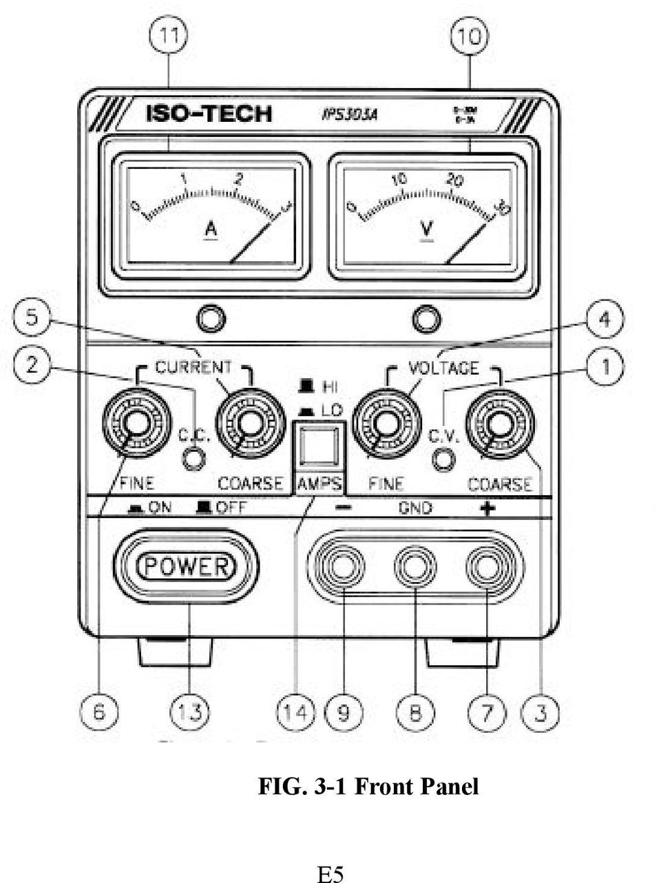
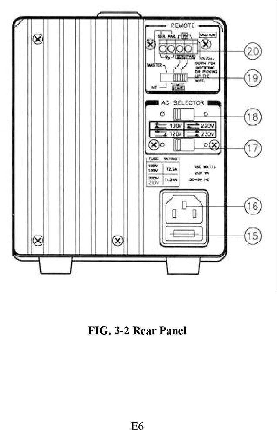
10 3. PANEL CONTROLS AND INDICATORS 3-1 Front panel (See Fig. 3-1) (1) CV Indicator lights when the power is on and this unit is in constant voltage operation. (2) CC Indicator lights when this unit is in constant current operation. (3) Voltage coarse for the coarse adjustment of the output voltage. (4) Voltage fine for the fine adjustment of the output voltage. (5) Current coarse for the coarse adjustment of the output current. (6) Current fine for the fine adjustment of the output current. (7) + output terminal positive polarity (Red). (8) GND terminal earth and chassis ground (Green). (9) output terminal negative polarity (Black). (10) meter indicates the output voltage (Analog type). (11) meter indicates the output current (Analog type). (12) A/V selects switch selects whether he meter indicates the output voltage or current. (13) Power control on/off switch. (14) Current HI/LO control current indicates HI/LO range SELECTS. 3-2 Rear panel (See Fig. 3-2) (15) Fuse holder (16) Power cord (17) AC selects switch With (18) switch selects the line voltage at the high end (right position) of the range 120V or 230V and at the low end (left position) of the range 100V or 220V. (18) AC selects switch Selects the line voltage is in the 100V-120V range (left position) or in the 220V-230V in the range (right position). (19) Master-Slave switch Selects for Master (internal control) or Slave (external remote control) tracking operation. (20) Input-Output connector With (19) Master-Slave switch selects, permit from the Master unit (SER. or PAR.) output connected to Slave unit (SER. or PAR.) inputs. E4
 + output terminal positive polarity (Red). (8) GND terminal earth and chassis ground (Green). (9) output terminal negative polarity (Black). (10) meter indicates the output voltage (Analog type).")
11 FIG. 3-1 Front Panel E5
12 FIG. 3-2 Rear Panel E6
13 4. OPERATION INSTRUCTIONS 4-1 Precaution (1) AC input AC input should be within the range of line voltage ±10% 50/60Hz. WARNING. To avoid electrical shock, the power cord protective grounding conductor must be connected to ground. (2) Installation Avoid using the power supply in a place where the ambient temperature exceeds 40ºC. The heat sink located at the rear of the power supply must have sufficient air space for radiation. CAUTION. To avoid damaging the power supply, do not use it in a place where ambient temperature exceeds 40ºC. (3) Output voltage overshoot Voltage between output terminals never exceeds the preset value when the power is turned on or off. 4-2 Setting Current Limit (1) Determine the maximum safe current for the device to be powered. (2) Temporarily short the (+) and (-) terminals of the power supply together with a test lead. (3) Rotate the COARSE VOLTAGE control away from zero sufficiently for the CC indicator to light. (4) Adjust the CURRENT control for the desired current limit. Read the current value on the Ammeter. (5) The current limit (overload protection) has now been preset. Do not change the CURRENT control setting after this step. (6) Remove the short between the (+) and (-) terminals and hook up for constant voltage operation. 4-3 Constant Voltage / Constant Current Characteristic The working characteristic of this series Power Supplies is called a constant voltage/constant current automatic crossover type. This permits continuous transition from constant current to constant voltage modes in response to the load change. The intersection of constant voltage and constant current modes is called the crossover point. Fig. 4-1 shows the relationship between this crossover point and the load. For example, if the load is such that the power supply is operating in the constant voltage mode, a regulated output voltage is provided. The output voltage remains constant as the load increases, up until the point where the preset current limit is reached. At that point, the output current becomes constant and the output voltage drop is proportional to further increases in load. The crossover point is indicated by the front panel LED indicators. The crossover point is reached when the CV E7

14 indicator goes off and the CC indicator comes on. Fig. 4-1 Constant Voltage/Constant Current Characteristic Similarly, crossover from the constant current to the constant voltage mode automatically occurs from a decrease in load. A good example of this would be seen when charging a 12-volt battery. Initially, the open circuit voltage of the power supply may be preset for 13.8 volts. A low battery will place a heavy load on the supply and it will operate in the constant current mode, which may be adjusted for a 1 amp charging rate. As the battery becomes charged, and its voltage approaches 13.8 volts, its load decreases to the point where it no longer demands the full 1 amp charging rate. This is the crossover point where the power supply goes into the constant voltage mode. E8

15 4-4 Operation Mode (1) Single Operation Use the supply as it is for single operation. A. Set power switch to OFF position. B. Make sure that line voltage is correct for the input power voltage. C. Plug power cord into the power outlet. D. Set power switch to ON position. E. Adjust Voltage and Current control to the desired output voltage and current. F. Connect the external load to the output binding posts. Make sure both + and terminals are connected correctly. (2) Series Operation (only applies when using identical models) Two power supplies can be connected in series to provide a higher voltage and rating current output. See Fig. 4-2 for the connection scheme. A. Set power switch to OFF position. B. Set the MASTER power supply INT-SLAVE switch to INT position and set the SLAVE power supply INT-SLAVE switch to SER-SLAVE position. C. Connect the MASTER power supply SER output terminal to the SLAVE power supply SER input. D. Set power switch to ON position. WARNING: Voltages of more than 60V DC are a lethal shock hazard to the user. Be careful when connecting power supplies in series to achieve voltages higher than 60V DC total or 60V DC between any connection and earth ground. E9
 Series Operation (only applies when using identical models) Two power supplies can be connected in series to provide a higher voltage and rating current output. See Fig.")
16 Fig. 4-2 Connecting Two Power Supplies in Series E10

17 E. When connected in series, the VOLTAGE controls of each power exercise control supply over 0 to rating range. Add the two voltmeter readings together to determine the total output voltage, or an external voltmeter may be connected across the load. F. Load current may be monitored from either supply; the readings will be identical since they are connected in series. Also, since the supplies are connected in series, it is only necessary to set the current limit on one of the supplies; the other may be set for maximum. (3) Parallel Operation Two power supplies may be connected in parallel to provide rating voltage and higher current output. See Fig. 4-3 for the connection scheme. A. Set power switch to "OFF" position. B. Set the MASTER power supply INT-SLAVE switch to INT position and set the SLAVE power supply INT-SLAVE switch to PAR-SLAVE position. C. Create a link from the MASTER power supply PAR output terminal to the SLAVE power supply PAR input. D. When connected in parallel ensure that the SLAVE VOLTAGE and CURRENT controls are set to maximum, then adjust the MASTER controls to set the required VOLTAGE and CURRENT. E. The output voltage may be monitored from either supply; the readings will be identical since they are connected in parallel, however the total output current can be determined by adding the two ammeter readings together, or an external ammeter may be connected in series with the load. F. Set the power switches to ON position. G. Note: For correct operation ensure the MASTER output voltage is lower than V of the SLAVE output voltage. E11

18 Fig. 4-3 Connecting Two Power Supplies in Parallel E12

19 (4) Remote control of output voltage The output voltage of the power supply can be remote-controlled with an external voltage; the connection required is shown in Fig Fig. 4-4 A. Set the power supply INT-SLAVE switch to SER-SLAVE position. B. The + line of control voltage source is connected to the SER input terminal and the - line of control voltage source is connected to the power supply output + terminal. C. The output voltage Eo is calculated as follows: Er Ec Eo = 10 Eo: Output voltage of the power supply. Er: Rated voltage of the power supply. Ec: Remote control voltage. 0 Ec approx.10v. D. For the remote voltage source Ec, use a device which provides a stable, low-noise voltage source (an RS IPS series power supply or an equivalent device). E13

20 (5) Remote control of output current The output current of the power supply can be remote-controlled with an external voltage; the connection required is shown in Fig Fig. 4-5 A. Set the power supply INT-SLAVE switch to PAR-SLAVE position. B. The - line of control voltage source is connected to the PAR input terminal and the + line of control voltage source is connected to the power supply output + terminal. C. The output current Io is calculated as follows: Ir Ec Io = 10 Io: Output current of the power supply. Ir: Rated current of the power supply. Ec: Remote control voltage. 0 Ec approx.10v. D. For the remote control voltage source Ec, use a device which provides a stable, low-noise voltage source (an RS IPS series power supply or an equivalent device). (6) Dynamic Load Operation & Application: A. When selecting the dynamic load function, the maximum peak current is 1.7 times the rated current. These features are only suitable for the testing of Audio circuitry. Please change jump wire J108 to the ON position (please refer to Fig. 5-1). E14

21 5. MAINTENANCE WARNING The following instructions are for use by qualified personnel only. To avoid electrical shock, do not perform any servicing other than contained in the operating instructions unless you are qualified to do so. 5-1 Fuse Replacement If the fuse is blown, the CV or CC indicators will not light and the power supply will not operate. The fuse should not normally blow unless a problem has developed in the unit. Try to determine and correct cause of the blown fuse, then replace only with a fuse of the correct rating and type. The fuse is located on the rear panel (see Fig. 3-2). WARNING: For continued fire protection. Replace fuse only with 250V fuse of the specified type and rating, and disconnect the power cord before replacing fuse. 5-2 Line Voltage Conversion The primary winding of the power transformer is tapped to permit operation from 100, 120, 220, or 230 VAC, 50/60 Hz line voltage. Conversion from one line voltage to another is done by changing AC selects switch as shown in Fig The unit is set to default line voltage. To convert to different line voltage, perform the following procedure: (1) Make sure the power cord is unplugged. (2) Change the AC selects switch to the desired line voltage position. (3) A change in line voltage may also require a corresponding change of fuse value. Install the correct fuse value as listed on rear panel. 5-3 Internal Adjustments The unit was accurately adjusted at the factory before shipment. Readjustment is recommended only if repairs have been made in a circuit affecting adjustment accuracy, or if you have a reason to believe the unit is out of accuracy. However, adjustments should be attempted only if a multimeter with an accuracy of ±0.1% dcv or better is available. E15
22 If readjustment is required, use the following procedure. Locations of the adjustments are shown in Fig. 5-1 and Fig (1) Adjustment of the Rating Voltage A. Connect an accurate (±0.1%) external multimeter to measure the DC voltage at output terminals of the power supply. B. Set the COARSE and FINE VOLTAGE controls to minimum (fully counterclockwise). C. Adjust trimmer pot VR106 for a reading of 0 volts on the multimeter. D. Turn the COARSE and FINE VOLTAGE controls to maximum (fully clockwise). E. Adjust trimmer pot VR105 for a reading of rate volts 1.05 on the multimeter. F. Set the COARSE and FINE VOLTAGE controls for a reading of rate volts on the multimeter. G. Adjust trimmer pot VR301 (VR201 digital type) for a reading of rate volts on the voltmeter (Digital panel meter, digital type) of the power supply. (2) Adjustment of the Rating Current A. Set the CURRENT control to minimum (fully counterclockwise). B. Connect the external multimeter to measure DC current at the output terminals of the power supply. C. Set the COARSE and FINE CURRENT controls to minimum (fully counterclockwise). D. Adjust trimmer pot VR107 for a reading of 0 amps on the multimeter. E. Set the COARSE and FINE VOLTAGE controls to a centered position. F. Set the COARSE and FINE CURRENT controls to maximum (fully clockwise). G. Adjust trimmer pot VR108 for a reading of 1/2 rate amps 1.05 on the multimeter (LO current). H. Adjust trimmer pot VR109 for a reading of rate amps 1.05 on the multimeter (HI current). I. Readjust the CURRENT control for a reading of rate amps on the multimeter. J. Adjust trimmer pot VR110 (HI), VR111 (LO) to calibrate the Ammeter or Digital panel meter of the power supply for the same reading as the multimeter. 5-4 Cleaning To clean the power supply, use a soft cloth dampened in a solution of mild detergent and water. Do not spray cleaner directly onto the instrument, since it may leak into the cabinet and cause damage. Do not use chemicals containing benzine, benzene, toluene, xylene, acetone, or similar solvents. Do not use abrasive cleaners on any portion of the power supply. E16
23 Fig. 5-1 Adjustment Location E17
24 Fig. 5-2 Adjustment Location E18
How To Use A Cdm250 Digital Multimeter
 User Manual CDM250 Digital Multimeter 070-6736-03 Copyright Tektronix, Inc. 1987. All rights reserved. Tektronix products are covered by U.S. and foreign patents, issued and pending. Information in this
User Manual. CFG253 3 MHz Function Generator 070-8362-04
 User Manual CFG253 3 MHz Function Generator 070-8362-04 Copyright Tektronix, Inc. 1993. All rights reserved. Tektronix products are covered by U.S. and foreign patents, issued and pending. Information
EPM3. Phase Sequence and Motor Rotation Tester. Users Manual
 EPM3 Phase Sequence and Motor Rotation Tester Users Manual 1 L1 L2 L3 2 3 A B C CAT 600V 3-PHASE TESTER 5 TEST M1 M2 BATT M3 EPM3 MOTOR ROTATION TESTER EPM3 MOTOR ROTATION DETERMINED WHILE FACING MOTOR
Dual Display Digital Multimeter
 Dual Display Digital Multimeter GDM-8246 GW INSTEK PART NO. 82DM-82460MG1 This manual contains proprietary information, which is protected by copyrights. All rights are reserved. No part of this manual
Series AMEPR30-AZ up to 2.5A AC-DC / DC-DC LED Driver / Converter
 FEATURES: Click on Series name for product info on aimtec.com Models Single output Model Max Output Power (W) 1 AC-DC Constant Current or Constant Over temperature protection Voltage LED Driver Over current
AutoRanging Digital MultiMeter
 Owner's Manual AutoRanging Digital MultiMeter Model No. 82139 CAUTION: Read, understand and follow Safety Rules and Operating Instructions in this manual before using this product. Safety Operation Maintenance
Manual Ranging MultiMeter
 Owner s Manual Manual Ranging MultiMeter Model 82345 CAUTION: Read, understand and follow Safety Rules and Operating Instructions in this manual before using this product.! Safety! Operation! Maintenance!
User's Guide. True RMS Industrial Multimeter
 User's Guide 97650 True RMS Industrial Multimeter Ω C ã F ã 10A V µ 10A V ã ã ma A Introduction This meter measures AC/DC Voltage, AC/DC Current, Resistance, Capacitance, Frequency (electrical & electronic),
REGULINE 600VA / 1000VA REGULATOR USER MANUAL
 REGULINE 600VA / 1000VA REGULATOR USER MANUAL TUNÇMATİK REGULINE SERIES AUTOMATIC VOLTAGE REGULATOR Models: REGULINE 600VA / REGULINE 1000VA Principle of Operation Automatic Voltage Regulators regulate
Model 1756 Test Lead Kit
 Keithley Instruments 28775 Aurora Road Cleveland, Ohio 44139 1-888-KEITHLEY http://www.keithley.com Model 1756 Test Lead Kit Gerneral Purpose Test Lead Information Description These test leads allow you
Agilent 87421A/87422A Power Supply
 Agilent 87421A/87422A Power Supply Technical Overview Designed specifically for Agilent Technologies microwave system amplifiers Bias cable permits remote placement Compact size for easy system integration
The table below lists the symbols used on the Clamp and/or in this manual. Important Information. See manual.
 i800 AC Current Clamp Instruction Sheet Introduction The i800 AC Current Clamp, the Clamp, has been designed for use with multimeters, recorders, power analyzers, safety testers, etc., for accurate non-intrusive
Troubleshooting Guide, Freedom and Fleet Power Inverter/Chargers
 Technical Note Freedom/Fleet Power 512-0084-01-01 Rev 1 Troubleshooting Guide, Freedom and Fleet Power Inverter/Chargers Overview This document is a guide for troubleshooting inverters, battery chargers,
UT202A Operating Manual. Contents
 Title Contents Page Overview Unpacking Inspection Safety Information Rules for Safe Operation International Electrical Symbols The Meter Structure Functional Buttons and auto power off Display Symbols
USER S MANUAL. MaxPower 400-600 UPS. Uninterruptible Power System 28-2MAXPO0018
 USER S MANUAL MaxPower 400-600 UPS Uninterruptible Power System 28-2MAXPO0018 IMPORTANT SAFETY INSTRUCTIONS SAVE THESE INSTRUCTIONS This manual contains important instructions for models MaxPower 400 and
SX460. Generator Automatic Voltage Regulator Operation Manual
 SX460 Generator Automatic Voltage Regulator Operation Manual Self Excited Automatic Voltage Regulator Compatible with Newage SX460* * Use for reference purpose only and not a genuine Newage product. 1.
Instructions A622 100 Amp AC/DC Current Probe 070-8883-03
 Instructions A622 100 Amp AC/DC Current Probe 070-8883-03 Revision A www.tektronix.com 070888303 Copyright Tektronix, Inc. All rights reserved. Tektronix products are covered by U.S. and foreign patents,
RISH CON - Hz. Salient Features : Application : Product Features: FREQUENCY TRANSDUCER
 Application : The RISH CON - Hz transducer is used for frequency measurement. The output signal is proportional to measured frequency and is either load independent DC Current or load independent DC Voltage.
LOXONE 12 Channel Amplifier
 LOXONE 12 Channel Amplifier Item no.: 200110 Thank you for purchasing the Loxone Twelve Channel Amplifier. The versatility of the Amplifier makes it the perfect choice for almost every type of custom multi-room
Daker DK 1, 2, 3 kva. Manuel d installation Installation manual. Part. LE05334AC-07/13-01 GF
 Daker DK 1, 2, 3 kva Manuel d installation Installation manual Part. LE05334AC-07/13-01 GF Daker DK 1, 2, 3 kva Index 1 Introduction 24 2 Conditions of use 24 3 LCD Panel 25 4 Installation 28 5 UPS communicator
i410/i1010 AC/DC Current Clamp
 /i1010 AC/DC Current Clamp Instruction Sheet Safety Information XW Read First: Safety Information To ensure safe operation and service of the current clamp, follow these instructions: Read all operating
User Guide. Model 380260 Insulation Tester / Megohmmeter
 User Guide Model 380260 Insulation Tester / Megohmmeter Introduction Congratulations on your purchase of Extech s Insulation Tester/Megohmmeter. The Model 380260 provides three test ranges plus continuity
How To Use A Power Supply Unit (Upu)
") BRAVER UPS (Uninterruptible Power System) User s Manual Safety CAUTION! This UPS utilizes voltages that may be hazardous. Do not attempt to disassemble the unit. The unit contains no user replaceable parts.
BRAVER UPS (Uninterruptible Power System) User s Manual Safety CAUTION! This UPS utilizes voltages that may be hazardous. Do not attempt to disassemble the unit. The unit contains no user replaceable parts.
STEREO PREAMPLIFIER INSTRUCTIONS FOR USE
 XX STEREO PREAMPLIFIER INSTRUCTIONS FOR USE Thank you for purchasing the Musical Fidelity A5 CR Preamplifier. Used properly and carefully, it should give many years of outstanding musical reproduction.
1.44 kw Programmable DC Power Supplies XLN Series
 Data sheet 1.44 kw Programmable DC Power Supplies XLN Series New Family of High Density System Power Supplies The B&K Precision XLN series are compact, programmable, single-output DC power supplies, suitable
Model UT33A: OPERATING MANUAL Table of Contents (1)
") Table of Contents (1) Title Overview Unpacking Inspection Safety Information Rules For Safe Operation International Electrical Symbols The Meter structure Functional Buttons LCD Display Measurement Operation
Table of Contents (1) Title Overview Unpacking Inspection Safety Information Rules For Safe Operation International Electrical Symbols The Meter structure Functional Buttons LCD Display Measurement Operation
Model UT201/202: OPERATING MANUAL. Table of Contents
 Table of Contents Title Overview Unpacking Inspection Safety Information Rules For Safe Operation International Electrical Symbols The Meter Structure Rotary Switch Functional Buttons The Effectiveness
MCR-VDC-UI-B-DC. Voltage Transducer for DC Voltages. INTERFACE Data Sheet 100260_en_01. 1 Description
 Voltage Transducer for DC Voltages TERFACE Data Sheet 000_en_0 PHOENIX CONTACT - /00 Description The MCR voltage transducer measures DC voltages in several signal ranges from 0... ±0 V DC to 0... ±0 V
12-Volt 10-Amp Regulated Power Supply
 22-506.fm Page 1 Friday, August 6, 1999 12:55 PM Cat. No. 22-506 OWNER S MANUAL Please read before using this equipment. 12-Volt 10-Amp Regulated Power Supply 22-506.fm Page 2 Friday, August 6, 1999 12:55
Duct Humidity Transmitter
 SDC-H Duct Humidity Transmitter Features Replaceable sensor element Humidity measurement for air ducts Minimum and maximum value memory 0 0V, 0 0mA or 0V, 4 0mA measuring signals selectable with jumpers
US Installation Manual Smappee Monitor
 US Installation Manual Smappee Monitor Version 1.3 English, US, version 1.3, revision 23, as of October 23, 2014, 2013 Smappee NV. All rights reserved. Specifications are subject to change without notice.
HCS-3300/3302/3304 USB Remote Programmable Laboratory Grade Switching Mode Power Supply
 1. INTRODUCTION HCS-3300/3302/3304 USB Remote Programmable Laboratory Grade Switching Mode Power Supply User Manual This family of efficient, upgraded SMPS with small form factor, auto cross over CV CC,
Lab 3 - DC Circuits and Ohm s Law
 Lab 3 DC Circuits and Ohm s Law L3-1 Name Date Partners Lab 3 - DC Circuits and Ohm s Law OBJECTIES To learn to apply the concept of potential difference (voltage) to explain the action of a battery in
User s Manual Before using the inverter, you need to read and save the safety instructions.
 User s Manual Before using the inverter, you need to read and save the safety instructions. STI SERIES (STI200, STI300, STI500, STI700, STI1000) Power Frequency Pure Sine Wave Inverter The information
Processor. Installation Guide
 Processor Installation Guide Land Instruments International Dronfield, S18 1DJ England Telephone: (01246) 417691 Facsimile: (01246) 410585 Email: [email protected] Internet: www.landinst.com
±15 V Current-Limited Power Supply
 USER S GUIDE ±15 V Current-Limited Power Supply Model 0901 Newport Corporation 3635 Peterson Way Santa Clara, CA 95054 www.newport.com/newfocus Warranty Newport Corporation guarantees its products to be
Multi-Range Programmable DC Power Supplies 9115 Series
 Data Sheet Multi-Range Programmable DC Power Supplies 1200 W / 3000 W Multi-Range DC Power Supplies Features & Benefits Any model can replace several supplies on your bench or in your rack. Unlike conventional
PD30ETB20xxIS. Photoelectrics, Background Suppression reflective with IR light. Main features. Description
 Photoelectrics, Background Suppression reflective with IR light Main features Description The PD30ET... stainless steel sensors are built with high-quality materials and designed for harsh environments.
User Guide. www.burntec.com. 4 wire Earth Resistance Tester Model GRT300
 User Guide 4 wire Earth Resistance Tester Model GRT300 Introduction Congratulations on your purchase of Extech s 4 Wire Earth Resistance Tester. The Model GRT300 has been designed and tested according
PUMP DRIVES ENTRAÎNEMENTS DE POMPES PUMPENANTRIEBE MOTOR DE BOMBAS UNITÀ DI CONTROLLO POMPA 77410-10 77411-00 OPERATING MANUAL: MODE D EMPLOI:
 OPERATING MANUAL: PUMP DRIVES pages 1-10 MODE D EMPLOI: ENTRAÎNEMENTS DE POMPES F1-F10 BETRIEBSANLEITUNG: PUMPENANTRIEBE D1-D10 77411-00 pump drive Model Nos. N de modèle Modellnummer Número de modelo
Power Supply Unit, Primary Switched, Narrow Design MINI-PS-12-24DC/24DC/1
 Power Supply Unit, Primary Switched, Narrow Design MINI POWER provides: Extra narrow design with widths of 22.5 mm, 45 mm, and 67.5 mm (0.886, 1.772, and 2.657 in.) Global use due to a wide-range input
CONNECTOR AMPLIFIER FOR PROPORTIONAL VALVES (4-20 ma Input Version)
") TECHNICAL DATASHEET #TD1102AX CONNECTOR AMPLIFIER FOR PROPORTIONAL VALVES (4-20 ma Input Version) Part Number: Connector Amplifier CAPV-H-4-20MA-x complete with cable CAPV-4C-yM Where: x = current output
TECHNICAL DATASHEET #TD1102AX CONNECTOR AMPLIFIER FOR PROPORTIONAL VALVES (4-20 ma Input Version) Part Number: Connector Amplifier CAPV-H-4-20MA-x complete with cable CAPV-4C-yM Where: x = current output
Power supply unit Model: PAC-SC50KUA
 Building Air Conditioning Control System Power supply unit Model: PAC-SC50KUA Installation Manual Contents 1. Safety precautions... 1 2. Product feature... 2 1. Specification... 2 2. Appearance... 2 3.
User Manual for CH-PFC76810
 AA Portable Power Corp www.batteryspace.com, Email: [email protected] User Manual for CH-PFC76810 1. Overview The CH-PFC76810 charger is suitable for charging lithium ion battery packs such as those
Instruction Manual. 2in1 LAN Tester & Multimeter. Model: LA-1011
 Instruction Manual 2in1 LAN Tester & Multimeter Model: LA-1011 1 Contents Introduction... Features... Safety Precautions.. Meter Description... Electrical Specification... Operation.. AutoRanging Multimeter.
TIG INVERTER INSTRUCTION MANUAL
 TIG INVERTER INSTRUCTION MANUAL Contents Warning General Description Block Diagram Main Parameters Circuit Diagram Installation and Operation Caution Maintenance Spare Parts List Troubleshooting 3 4 4
IDEAL INDUSTRIES, INC. TECHNICAL MANUAL MODELS: 61-763 61-765
 IDEAL INDUSTRIES, INC. TECHNICAL MANUAL MODELS: 61-763 61-765 The Service Information provides the following information: Precautions and safety information Specifications Performance test procedure Calibration
Distributed By TestEquity - www.testequity.com - 800-732-3457
 DC Power Supply GPD-3303 Series USER MANUAL GW INSTEK PART NO. This manual contains proprietary information, which is protected by copyrights. All rights are reserved. No part of this manual may be photocopied,
Current valve. for AC 24 V pulse/pause control of electrical loads up to 30 kw
 4 937 DESIO Current valve for AC 24 V pulse/pause control of electrical loads up to 30 kw SEA45.1 Use The current valve is used for the control of electric heating elements in heating, ventilation and
victron energie USER MANUAL GEBRUIKSAANWIJZING GEBRAUCHSANWEISUNG Victron Atlas 12/850
 victron energie USER MANUAL GEBRUIKSAANWIJZING GEBRAUCHSANWEISUNG Victron Atlas 12/850 SECTIONS ENGLISH 1 NEDERLANDS 27 DEUTSCH 55 This page intentionally left blank. ENGLISH USER MANUAL Victron Atlas
CONTENTS. PAGE Chapter 1 General Information 1. Chapter 2 Setup 4 DP450-VDC 7 DP450-VAC 7 DP450-DCC 7 DP450-F 8 DP450-HACC 9 DP450-HDCC 11 DP450-E 13
 CONTENTS PAGE Chapter 1 General Information 1 Chapter 2 Setup 4 DP450-VDC 7 DP450-VAC 7 DP450-DCC 7 DP450-F 8 DP450-HACC 9 DP450-HDCC 11 DP450-E 13 Chapter 3 Alarm/Excitation Options 15 Wiring 17 Chapter
TECHNICAL DATASHEET #TD1404AX PWM CONTROLLED SOLENOID DRIVER
 TECHNICAL DATASHEET #TD1404AX PWM CONTROLLED SOLENOID DRIVER (PWM Input, 1.2A or 2A Output, Metal Box or PCB) PCB Board - P/N: PWMC-PCB-2A, PWMC-PCB-1.2A Packaged Driver (metal box with 1.5 m (5 ft.) cable)
FLUORESCENT UV- RING LIGHT OPERATING INSTRUCTION
 FLUORESCENT UV- RING LIGHT OPERATING INSTRUCTION Caution! UV-radiation of this device is in the range of UV-A (320-400 nm). Direct exposure to eyes shall therefore be avoided. UV protection glasses shall
USER INSTRUCTIONS FOR 10 LITRE PORTABLE DEHUMIDIFIER MODEL NO. DHMD102
 USER INSTRUCTIONS FOR 10 LITRE PORTABLE DEHUMIDIFIER MODEL NO. DHMD102 THANK YOU FOR CHOOSING YOUR NEW DEHUMIDIFIER. BEFORE USING THE UNIT READ THESE INSTRUCTIONS FULLY AND RETAIN THEM FOR FUTURE REFERENCE
Drayton Digistat +2RF/+3RF
 /+3RF Programmable Room Thermostat Wireless Model: RF700/22090 Model: RF701/22092 Power Supply: Battery - Thermostat Mains - Digistat SCR Invensys Controls Europe Customer Service Tel: 0845 130 5522 Customer
Guidance for upgrading to GB4943.1-2011 (IEC 60950-1: 2005, MOD)
") Guidance for upgrading to GB4943.1-2011 (IEC 60950-1: 2005, MOD) Note: This guidance document is a translation of official Chinese document which is issued by CQC (China Quality Certification Center) on
Guidance for upgrading to GB4943.1-2011 (IEC 60950-1: 2005, MOD) Note: This guidance document is a translation of official Chinese document which is issued by CQC (China Quality Certification Center) on
Match. GE Digital Energy. Uninterruptible Power Supply 500-1500 VA. Technology for the Digital World. Match UPS. GE Digital Energy.
 Match Uninterruptible Power Supply 500-1500 VA Manufactured by: General Electric Company Telephone +41 (0)91 / 850 51 51 CH 6595 Riazzino (Locarno) Fax +41 (0)91 / 850 51 44 Switzerland Website www.gedigitalenergy.com
IMPORTANT SAFETY INSTRUCTIONS WARNING READ AND SAVE THESE OPERATING AND SAFETY INSTRUCTIONS BEFORE USING THIS HEATER.
 THERMAWAVE CERAMIC HEATER Model HZ-850 Series Model HZ-860 Series IMPORTANT SAFETY INSTRUCTIONS WARNING READ AND SAVE THESE OPERATING AND SAFETY INSTRUCTIONS BEFORE USING THIS HEATER. Warning Failure to
DUAL%CHANNEL BROADBAND%LINEAR%AMPLIFIER Model&A800D
 ELECTRONICS AB DUAL%CHANNEL BROADBAND%LINEAR%AMPLIFIER Model&A800D & HIGH&VOLTAGE& FIXED&GAIN& BROADBAND & 800Vpp&60mA& 100x& DC&to&ca&200&kHz & LOW&OUTPUT&IMPEDANCE& HIGH&SLEW&RATE &
ST Series POWER SUPPLIES USER INSTRUCTIONS
 Introduction These instructions detail the installation and operation requirements for the ST20 & ST35 power supplies. These have been designed for operation in RV s providing a DC power system, with optional
VOLTAGE/CURRENT CALIBRATOR ISO-TECH ILC-421
 VOLTAGE/CURRENT CALIBRATOR ISO-TECH ILC-421 TABLE OF CONTENTS 1. FEATURES... 1 2. SPECIFICATIONS... 1 2-1 General Specifications...1 2-2 Electrical Specifications... 2 3. FRONT PANEL DESCRIPTION... 4 3-1
HM-W536 Install Guide
 HM-W536 Install Guide 9/13/2013 IMPORTANT SAFETY INSTRUCTIONS Warning - When using electrical devices, basic safety precautions should be followed to reduce the risk of fire, electrical shock or injury.
Single Day Alarm Clock with. Bluetooth and USB Play-through
 Single Day Alarm Clock with Bluetooth and USB Play-through MODEL : BSC 200 READ THIS INSTRUCTION MANUAL BEFORE OPERATING THE APPLIANCE. SAVE THIS MANUAL FOR FUTURE REFERENCE. TABLE OF CONTENTS IMPORTANT
64-CHANNEL INTEGRATED AMPLIFIER
 Panasonic 64-CHANNEL INTEGRATED AMPLIFIER Operating Instructions P/N: SU-MED640E Caution for AC main lead FOR YOUR SAFETY, PLEASE READ THE FOLLOWING TEXT CAREFULLY This product is equipped with 2 types
Multi-Range Programmable DC Power Supplies 9115 Series
 Data Sheet 1200 W Multi-Range DC Power Supplies Features & Benefits Any 9115 series model can replace several supplies on your bench or in your rack. Unlike conventional supplies with fixed output ratings,
7 FUNCTION DIGITAL MULTIMETER
 7 FUNCTION DIGITAL MULTIMETER 90899 OPERATING INSTRUCTIONS 3491 Mission Oaks Blvd., Camarillo, CA 93011 Visit our Web site at http://www.harborfreight.com Copyright 2004 by Harbor Freight Tools. All rights
User s Manual AURORA 1.2K/2.2K
 User s Manual AURORA 1.2K/2.2K Uninterruptible Power System Safety CAUTION This UPS utilizes voltages that may be hazardous. Do not attempt to disassemble the unit. The unit contains no user serviceable
Declaration of Conformity. Safety
 CONTENTS PAGE 1. Product Introduction...... 1 2. Safety Information..... 3 3. Technical Specification... 7 4. Panel Controls and Indicator.... 9 5. Functional Description of Operation Element..... 12 6.
Multi Tube Rotator. Model No. 4632Q 4632-1CE 4632-1CECN 057-213-00 11/05/11
 Multi Tube Rotator Model No. 4632Q 4632-1CE 4632-1CECN 057-213-00 11/05/11 Table of Contents Safety Information...3 Alert Signals...3 Description...4 Specifications...5 Power Requirements...5 Shaker Motion...5
Service manual. Website: www.andico.com.au CAUTION - BEFORE SERVICING THE UNIT, READ THE SAFETY - PRECAUTIONS IN THIS MANUAL.
 Website: www.andico.com.au Service manual CAUTION - BEFORE SERVICING THE UNIT, READ THE SAFETY - PRECAUTIONS IN THIS MANUAL. - ONLY FOR AUTHORISED SERVICE PERSONNEL. MODELS: MPK1-09CR-QB8 MPK1-12ER-QB6
MIC-WKT and MIC-WKT-IR
 MIC-WKT and MIC-WKT-IR Installation Manual Bosch Security Systems EN Installation and Operation Manual MIC-WKTI and MIC-WKT-IR Installation Manual EN 2 MIC-WKT and MIC-WKT-IR Washer Pump Drive Card Kits
RIGOL. Quick Guide. DS1000CA Series Oscilloscope. Aug. 2011. RIGOL Technologies, Inc.
 Quick Guide DS1000CA Series Oscilloscope Aug. 2011 Technologies, Inc. Guaranty and Declaration Copyright 2011 Technologies, Inc. All Rights Reserved. Trademark Information is a registered trademark of
Model UT33B/C/D: OPERATING MANUAL Table of Contents (1)
") Table of Contents (1) Title Overview Unpacking Inspection Safety Information Rules For Safe Operation International Electrical Symbols The Meter structure Functional Buttons Measurement Operation A. DC
Table of Contents (1) Title Overview Unpacking Inspection Safety Information Rules For Safe Operation International Electrical Symbols The Meter structure Functional Buttons Measurement Operation A. DC
PSDC 08128. PSDC 12V/8A/8x1A Power supply for up to 8 analog cameras PTC/TOPIC.
 PSDC 08128 v.1.2 PSDC 12V/8A/8x1A Power supply for up to 8 analog cameras PTC/TOPIC. EN** Edition: 9 from 25.05.2015 Supersedes the edition: 8 from 12.12.2014 the 8x 1A/12V DC power output for powering
Introduction. Page 2 / 9
 Installation Manual English, US, version 1.1, as of November 13th, 2015 2015 Smappee NV. All rights reserved. Specifications are subject to change without notice. All product names are trademarks of their
Meaco 30L and Meaco 40L dehumidifier instruction manual
 Meaco 30L and Meaco 40L dehumidifier instruction manual Please read this instruction manual before using the dehumidifier and keep safe for future reference SAFETY INSTRUCTIONS PLEASE READ ALL INSTRUCTIONS
user manual smappee monitor
 user manual smappee monitor January 2014 (English), version 2.02 2013 smappee NV. All rights reserved. Specifications are subject to change without notice. All product names are trademarks of their respective
Operating Manual UWAPS-TINY Series
 Operating Manual UWAPS-TINY Series Powecon Oy WWW.POWECON.FI 1/9 Table of content 1 Warranty...3 2 Safety information...3 3 Abbreviations and terminology...3 4 List of appendices...4 5 Introduction...4
Antec TruePower User's Manual
 User s Manual Antec TruePower User's Manual Antec TruePower ATX12V power supply Models: TRUE330, TRUE380, TRUE430, TRUE480, TRUE550 Antec Low Noise Technology: The Antec TruePower power supply is equipped
1. SAFETY INFORMATION
 RS-232 Sound Level Meter 72-860A INSTRUCTION MANUAL www.tenma.com 1. SAFETY INFORMATION Read the following safety information carefully before attempting to operate or service the meter. Use the meter
12. Inspection and Maintenance
 12. and Maintenance Mandatory Be sure to inspect the inverter regularly and periodically to prevent it from breaking down because of the environment of use, such as temperature, humidity, dust and vibration,
MICROSENS. Central 48 V DC Power Supplies for PoE-Components. Description. Features
 Central 48 V DC Power Supplies for PoE-Components MICROSENS Description Active network equipment which is supporting the Power-over-Ethernet functions, typically requires a powerful 48 V DC power supply.
************* OWNER'S MANUAL BAMF800/2 BAMF1250/2 BAMF1800/2 BAMF2200/2 BAMF2600/2 BAMF1200/4 BAMF1600/4 BAMF2000/1D BAMF4000/1D BAMF5500/1D
 ************* OWNER'S MANUAL BAMF800/2 BAMF1250/2 BAMF1800/2 BAMF2200/2 BAMF2600/2 BAMF1200/4 BAMF1600/4 BAMF2000/1D BAMF4000/1D BAMF5500/1D INTRODUCTION Power Acoustik amplifiers provide high-performance
DCS Series 1 kw, 1.2 kw, & 3 kw
 DCS Series 1 kw, 1.2 kw, & 3 kw AVAILABLE WITH LXI STANDARD COMPLIANT ETHERNET Applications Automotive Electronics Rackmount ATE System Battery Charging DCS Series DCS Series: 1 kw, 1.2 kw, & 3 kw DCS
Instruction Manual. This manual covers models: 8-125E 60-18E 20-50E 80-13E 33-33E 150-7E 40-25E 300-3.5E 50-20E 600-1.7E
 DCS-E SERIES POWER SUPPLIES Instruction Manual This manual covers models: 8-125E 60-18E 20-50E 80-13E 33-33E 150-7E 40-25E 300-3.5E 50-20E 600-1.7E SORENSEN Division of Elgar 9250 Brown Deer Road San Diego,
Hot Water Urns. all models. Helpline. v3.0
 Hot Water Urns all models Helpline 01384 573999 instructions.indd 1 v3.0 02/06/2014 14:50 IMPORTANT INFORMATION - RETAIN FOR FUTURE USE When using any electrical appliance, basic safety precautions should
Ground Resistance Clamp On Tester
 USER MANUAL Ground Resistance Clamp On Tester MODEL 382357 Introduction Congratulations on your purchase of Extech s 382357 Ground Resistance Tester. This Clamp on device allows the user to measure ground
AudioJoG (TM) Pro 8 Connector PIN LABEL LED Connector PIN LABEL LED. Operations Manual 3.5mm & 6.35mm Mono/Stereo Jacks
 Pro 8 Connector PIN LABEL LED Connector PIN LABEL LED. Operations Manual 3.5mm & 6.35mm Mono/Stereo Jacks") LED/Connector pin identification table AudioJoG (TM) Pro 8 Connector PIN LABEL LED Connector PIN LABEL LED Operations Manual 3.5mm & 6.35mm Mono/Stereo Jacks 3,4,5 pole XLR Male & Female 3,5 & 8 pole 180
LED/Connector pin identification table AudioJoG (TM) Pro 8 Connector PIN LABEL LED Connector PIN LABEL LED Operations Manual 3.5mm & 6.35mm Mono/Stereo Jacks 3,4,5 pole XLR Male & Female 3,5 & 8 pole 180
Battery Charger For Nickel Cadmium and Nickel-Metal Hydride Rechargeable Batteries Model PSN Series
 Battery Charger For Nickel Cadmium and Nickel-Metal Hydride Rechargeable Batteries Model PSN Series Operating Instructions WARNING CONCERNING THE REMOVAL OF COVER: CAUTION: TO PREVENT THE RISK OF ELECTRIC
CONTROLS DATA MANAGEMENT PROCESS AUTOMATION EUROCUBE. General purpose single phase thyristors and solid state relays Product data.
 425 CONTROLS DATA MANAGEMENT PROCESS AUTOMATION EUROCUBE General purpose single phase thyristors and solid state relays Product data abc 425 EUROCUBE A complete range of low cost solid state relays and
Portable Air Conditioner
 Portable Air Conditioner Owner's Manual Model:3 in 1 12,000 Btu/h Series 3 Please read this owner s manual carefully before operation and retain it for future reference. CONTENTS 1. SUMMARY...1 2. PORTABLE
Automatic Voltage Regulator User s Manual
 Resp. dept. R&D We reserve all rights in this document and in the information contained therein. Reproduction, use or disclosure to third parties without express authority is strictly forbidden. Copyright
TELIKOU Intercom System. MS-500(4+1 channel) Main Station Instruction Manual
 Main Station Instruction Manual") TELIKOU Intercom System MS-500(4+1 channel) Main Station Instruction Manual TELIKOU Systems All Rights Reserved While TELIKOU makes every attempt to maintain the accuracy of the information contained in
TELIKOU Intercom System MS-500(4+1 channel) Main Station Instruction Manual TELIKOU Systems All Rights Reserved While TELIKOU makes every attempt to maintain the accuracy of the information contained in
TELIKOU Intercom System. TM-200 Main Station. Instruction Manual
 Intercom System TM-200 Main Station Instruction Manual TELIKOU Systems All Rights Reserved I. Introduction Thank you for choosing TELIKOU intercom product. TM-200 main station is suitable for television
CPCI-3U-AC-300W-R. Rugged 300W AC Input 3U CompactPCI Power Supply. Electrical Specification for: Telkoor Part Number: 900-4602-0000
 Electrical Specification for: CPCI-3U-AC-300W-R Rugged 300W AC Input 3U CompactPCI Power Supply Telkoor Part Number: 900-4602-0000 GENERAL SCALE RELEASE DATE 12/9/06 SHEET 1 OF 6 REVISION HISTORY Rev Level
CX Zoner Installation & User Guide
 CX Zoner Installation & User Guide Cloud Electronics Limited 140 Staniforth Road, Sheffield, S9 3HF England Tel +44 (0)114 244 7051 Fax +44 (0)114 242 5462 e-mail [email protected] web site http://www.cloud.co.uk
TMS TANK MANAGEMENT SYSTEM
 TMS TANK MANAGEMENT SYSTEM Page 1 of 9 Operating Instructions GENERAL The Tank Management System is a bespoke design to control, monitor and accommodate efficient storage and dispensing of TMS. FUNCTIONS
Uninterruptible Power Supply ERA LED 1.5 ERA LED 2.0 ERA LED 2.6. User s manual
 Uninterruptible Power Supply ERA LED 1.5 ERA LED 2.0 ERA LED 2.6 User s manual Index Safety Warnings... 2 1 Introduction... 3 2 General Characteristics... 4 3 Receipt and site selection... 4 4 EXTERNAL
400-800. Series OMEGA WATTS POWER SUPPLY AC/DC SINGLE OR MULTIPLE OUTPUT. Flexible modular design. Programmable outputs** Power factor correction***
 INPUT Input protection Thermal protection Switching frequency internal fuse standard 100KHz Input with PFC : (MML400PFC, MML600, MML800) Input voltage range 85*-264VAC Inrush current (peak) MML400PFC
High PoE Midspans NPD-6001A NPD-9501A. en Installation Manual
 High PoE Midspans NPD-6001A NPD-9501A en Installation Manual High PoE Midspans Table of Contents en 3 Table of contents 1 Safety 4 1.1 About this Manual 4 1.2 Legal Information 4 1.3 Safety Precautions