THE 26-L BRAKE EQUIPMENT
|
|
|
- Georgia Shaw
- 9 years ago
- Views:
Transcription
1 INSTRUCTION PAMPHLET No. 74 June 1964 THE 26-L BRAKE EQUIPMENT with 26-C BRAKE VALVE and 26-F CONTROL VALVE arranged for SAFETY CONTROL OVERSPEED CONTROL DYNAMIC INTERLOCK and MULTIPLE-UNIT CONTROL for LOCOMOTIVES

2 THE 26-L BRAKE EQUIPMENT WITH 26-C BRAKE VALVE AND 26-F CONTROL VALVE ARRANGED FOR SAFETY CONTROL OVERSPEED CONTROL DYNAMIC INTERLOCK AND MULTIPLE-UNIT CONTROL FOR LOCOMOTIVES INSTRUCTION PAMPHLET NO. 74 JUNE 1964 (Supersedes Issue of September 1960)

3

4 CONTENTS The Equipment C Brake Valve... 5 Automatic Brake Operation... 9 Independent Brake Operation F Control Valve J-1 Relay Valve MU-2-A Valve F-1 Selector Valve Overspeed Control And Safety Control Functions With P-2 Brake Application Valve Overspeed Control And Safety Control Functions With P-2-A Brake Application Valve Break-In-Two Protection Feature With A-1 Charging Cut-Off Pilot Valve With Two B_-B-5 Relayair Valves Dynamic Brake Interlock Feature Automatic Split Reductions During Penalty Brake Application With A-1 Reduction Selector Valve Automatic Split Reductions During Penalty Brake Application And Temporary Suppression Of Overspeed Control Applications With A-2 Reduction Selector Valve Automatic Split Reductions During Penalty Brake Applications And Temporary And Permanent Suppression of Train Control Brake Application With C-1 Suppression Valve Operating Instructions Paqe -2-

5 THE EQUIPMENT The 26-L Brake Equipment is a combination automatic and independent locomotive brake of modern design which incorporates all of the operating features necessary for the control of freight and passenger train braking systems. This equipment employs as the major components a 26-C Brake Valve, a 26-F Control Valve and a high-capacity J type Relay Valve. The brake valve is a device by which the Engineman can initiate brake applications and releases on both the locomotive and its train, or on the locomotive independent of the train. The 26-F Control Valve automatically responds to the operation of the brake valve to develop and release air pressure for piloting the J Relay Valve to apply and release the locomotive brakes. The important features of this equipment are: 1. Prompt, flexible brake application and releases for smooth operation. 2. Multiple operation with previous types of locomotive brake equipments. 3. Pressure maintaining of brake pipe and brake cylinder pressures. 4. Safety Control 5. Overspeed Control 6. Train control with temporary and permanent suppression. 7. Split reduction penalty brake applications. 8. Power and dynamic brake cut-off during penalty brake applications. 9. Break-in-two protection. The data contained in this pamphlet is confined to a description of the operation and functions of only those devices that are unique to the 26-L Brake Equipment. -3-

6 Figure 1 26-C Brake Valve -4-

7 26-C BRAKE VALVE The 26-C Brake Valve, Figure 1, is a self-lapping type in which have been incorporated many modern design improvements. These include the replacement of the rotary valve by cam-operated O ring-packed spool valves and cam-operated poppet type valves to provide the control over the locomotive and train brakes. Also incorporated in the brake valve design is a cam-operated self-lapping regulating valve portion which functions to develop or dissipate equalizing reservoir pressure in proportion to the degree of brake valve handle movement in the handle quadrant. In turn, brake pipe pressure is developed and exhausted by a self-lapping type of relay valve that is piloted by equalizing reservoir pressure to maintain in the brake pipe the same pressure condition that exists in the equalizing reservoir. The 26-C Brake Valve mounts on a pipe bracket to which all pipe connections are made. The pipe connections are identified numerically as follows: 1 Brake Pipe 3 Switch Pipe 5 Equalizing Reservoir Control Pipe 8 Lock-Over Pipe 12 Emergency Switch Pipe 13 Actuating Pipe 15 Equalizing Reservoir Charging Pipe 20 Independent Application & Release Pipe 21 Safety Control Pipe 26 Suppression, Pipe 30 Main Reservoir Pipe 53 Brake Pipe Cut-Off Pipe The brake valve consists of two main portions; the automatic portion for regulating the brake pipe pressure controlling both the locomotive and train brakes, and the independent portion. The latter is a self-lapping independent brake valve for applying and releasing the locomotive brakes independently of the train brakes and for releasing an automatic brake application on the locomotive independently of the train brakes. The automatic brake valve portion is mounted on top of the pipe bracket and secured with four (4) studs, and the independent portion is attached to the front of the pipe bracket and is secured by three (3) cap screws. The 26-C Brake Valve is arranged for panel mounting. The entire valvular section is mounted behind the panel resulting in only the handle operating portion and a cut-off pilot valve section appearing on the front face of the panel. The automatic brake valve handle has six handle positions arranged from left to right as follows: -5-

8 Release (Running) Position: This position is for charging the equipment and releasing the locomotive and train brakes. It is located with the brake valve handle at the extreme left of the quadrant. Minimum Reduction Position: This position is located with the brake valve handle against the first raised portion on the quadrant to the right of Release position. With the brake valve handle moved to this position, a minimum brake pipe reduction is obtained. Service Position: This position consists of a sector of brake valve handle movement to the right of Release position. In moving the brake valve handle from left to right through this sector, the degree of brake application is increased until, with the handle at the extreme right of this sector, the handle is in full SERVICE position and a full service brake application is obtained. Suppression Position: This position is located with the handle against the second raised portion of the quadrant to the right of Release position. In addition to providing a full service brake application as with the brake valve handle in Service position, suppression of overspeed control and safety control application is obtained. Handle-Off Position: This position is located by the first quadrant notch to the right of Suppression position. The handle is removable in this position. This is the position in which the handle should be placed on trailing units of a multiple-unit locomotive or on loco motives being towed dead in a train. Emergency Position: This position is located to the extreme right of the brake valve quadrant. It is the position that must be used for making brake valve emergency brake applications and for resetting after any emergency application if break-in-two feature is available. -6-

9 The Cut-Off Pilot Valve portion, which provides the function of the familiar double heading cock, is for cutting in and cutting out the brake when desired. Threeposition and two-position Cut-Off Pilot Valves will be found in service. The threeposition type permits use of the locomotive in both passenger and freight service. Its three positions are PASS (passenger), FRT (freight) and OUT. The two position type is being employed on locomotives intended for freight service only and its positions are IN and OUT". The cut-off pilot Valve handle is positively held in each of its handle positions by spring loading and it is necessary to first depress the handle before it can be moved from one position to another. With the brake valve cut out by the Cut-Off Pilot Valve, pressure maintaining is cut off and it is then possible to make a brake pipe leakage test which will be covered later in the pamphlet under OPERATING INSTRUCTIONS. For all normal operations of the locomotive as a controlling unit, the cut-off pilot valve handle must be placed in FRT (freight) or PASS (passenger) position for the three position type and in IN position for the two-position type, depending upon the intended service for the locomotive. OUT position is to be used when hauling the locomotive dead or as a trailing unit in a multiple unit locomotive. The porting in the cut-off pilot valve portion also incorporates two check valves which provide either brake pipe pressure or main reservoir pressure to the brake pipe cut-off valve, depending upon the existing higher pressure. The 26-C Automatic Brake Valve Portion includes the following details: 1. A self-lapping type of regulating valve which is operated by a service cam fastened to and rotated with the handle shaft. It regulates the development of pressure to the equalizing reservoir charging pipe No. 15. This pressure is either piped through a P-2 or P-2-A Brake Application Valve, if one is employed, or directly to the No. 5 pipe beneath the brake valve from whence it is conveyed through passage 5 of the brake valve to the outer face of the diaphragm of the relay valve portion. Movement of the brake valve handle from Release position into the service sector causes the regulating portion to reduce equalizing reservoir pressure in proportion to the amount of handle movement, until in Full Service position the equalizing reservoir pressure is reduced sufficiently to produce a full service brake application. Adjustment of the equalizing reservoir pressure in Release position can be made by turning adjusting screw A at the end of the regulating valve portion. The selflapping feature of the regulating portion automatically maintains equalizing reservoir pressure against over-charges and against leakage. 2. The relay valve portion consisting of a diaphragm operated relay valve that establishes a pressure in the brake pipe equal to that in the equalizing reservoir at the time. It is capable of either supplying or venting brake pipe pressure and acts as the supply valve for charging brake pipe pressure on the locomotive and train with the brake valve handle in Release position. During automatic brake applications, reduction of equalizing reservoir pressure by the regulating valve causes the relay portion to correspondingly reduce brake pipe pressure. The relay valve portion will maintain brake pipe pressure against brake pipe leakage. -7-

10 3. The brake pipe cut-off valve which interrupts the flow of air from the relay valve supply valve to the brake pipe in the event of: (a) An emergency brake application (b) Positioning of the cut-off pilot valve in OUT position. (c) Operation of auxiliary devices connected to the brake valve which require interruption of the flow of air to the brake pipe for purposes of break-intwo protection. 4. The vent valve which is cam-operated from the brake valve handle shaft in Emergency position to produce a rapid drop in brake pipe pressure. The brake valve body is ported so that by the substitution of an emergency brake application portion for the vent valve cover, the vent valve can be actuated pneumatically by the venting of the No. 21 passage. 5. The emergency valve which is cam-operated from the brake valve handle shaft in Emergency position and which has two functions. It provides flow of main reservoir air to the No. 12 pipe for operation of power knockout switches and other auxiliary functions which may be required to be operated in Emergency position of the brake valve handle. The emergency valve also operates to quickly vent equalizing reservoir pressure at the brake valve in Emergency position to insure rapid and prompt venting of the brake pipe. 6. The suppression valve which is cam-operated from the brake valve handle shaft to provide main reservoir air supply to port No. 26 in Suppression, Handle-Off, and Emergency positions of the brake valve to suppress overspeed control and safety control brake applications. This valve also functions in these handle positions to close the No. 8 pipe for resetting the brake application valve prior to releasing these auxiliary brake applications. The suppression valve also functions to supply main reservoir air to port No. 3 with the brake valve handle in Release position and to keep open the equalizing reservoir cut-off valve via port 7 and the spool valve of the cut-off pilot valve. 7. The equalizing reservoir cut-off valve which is arranged to permit operation of trains employing both graduated and direct release type car equipments. In freight service with the cut-off pilot valve handle in either FRT or IN position, the equalizing reservoir cut-off valve is held open only in Release position, and only in that position can brake releases be made. In Passenger service with the cut-off pilot valve handle in PASS position, the equalizing reservoir cutoff valve is held open in all brake valve handle positions and the brakes can be released completely in Release position or can be graduated off in steps with the brake valve handle. -8-

11 Automatic Brake Operation Release Position This is the position of the 26-C Brake Valve for charging the brake pipe and brake system and for releasing an automatic pneumatic brake application. Main reservoir air enters port No. 30 at the pipe bracket, flows to the supply valve in the relay valve portion, to the spool valve of the suppression valve, thence to passage No. 3, and through the spool valve of the cut-off pilot valve to passage 7 and to the underside of the equalizing reservoir cut-off valve piston. Air pressure acting on the face of this piston will move it upwardly, forcing the charging check valve off its seat to its open position. Main reservoir air also flows from port No. 30 through the charging valve in the regulating valve portion, past the unseated check valve in the equalizing reservoir cut-off valve to passage 15 as well as to the face of the regulating valve diaphragm. Regulating handle A can be adjusted to regulate the value of the equalizing reservoir pressure to be developed by the regulating valve portion. This air pressure in Port No. 15 is likewise developed in the equalizing reservoir volume and port No. 5 either through the connection made in the P-2 or P-2-A Brake Application Valve or by the direct pipe connection made below the 26-C Brake Valve. Port No. 5 in the pipe bracket is connected to the spool valve of the emergency valve and to the chamber on the outer face of the relay valve diaphragm. A build-up of equalizing reservoir pressure on the outer face of the relay valve diaphragm will cause the diaphragm assembly and its attached stem to be moved inwardly to first seat the exhaust valve and then unseat the supply valve. This permits main reservoir air to flow past the unseated supply valve to the brake pipe port No. 1 and through the stabilizing choke to the chamber on the inner face of the relay valve diaphragm. Brake pipe air in port No. 1 also flows to the brake pipe cut-off valve, vent valve and thus to port No. 1 in the pipe bracket to which the brake pipe is connected. Whenever the brake pipe pressure build-up on the inner face of the relay valve diaphragm approaches equalizing reservoir pressure acting on the opposite side of the diaphragm, the diaphragm assembly and stem are positioned to permit the supply valve to become seated to terminate further flow of air from the main reservoir system to the brake pipe. The brake pipe is now fully charged; however, should brake pipe pressure decrease due to brake pipe leakage, the higher equalizing reservoir pressure acting on the outer face of the relay valve diaphragm will move the diaphragm assembly and stem inward to again unseat the supply valve to restore the brake pipe pressure to equalizing reservoir pressure, after which the supply valve will again become seated. This is Lap position of the relay valve portion. Service Position This position consists of a sector of handle movement to the right from Release position. As the handle is moved through this sector towards Service position, the -9-

12 brake pipe pressure reduction is increased gradually, until in full Service position a full service brake pipe reduction has been obtained. A minimum reduction notch is also contained in the brake valve quadrant and is located just a few degrees to the right of Release position by a raised portion in the service quadrant. Movement of the brake valve handle to this position provides a minimum reduction of pressure in the equalizing reservoir which results in a similar reduction in brake pipe pressure. When the automatic brake valve handle is moved to some intermediate service position, the suppression cam on the handle shaft positions the suppression valve to connect ports No. 3, 8 and 26 to atmosphere. The service cam on the handle shaft allows the exhaust valve in the regulating valve to be unseated to permit equalizing reservoir charging air to reduce. Normally, with port No. 3 exhausted and the cut-off pilot valve in FRT position, the equalizing reservoir cut-off valve is closed, but as soon as a pressure differential is set up across the cut-off valve check valve by the reduction of equalizing reservoir charging air on top of the check valve, the check valve is unseated and equalizing reservoir air can then flow past the check valve and regulating valve exhaust valve to atmosphere to reduce equalizing reservoir pressure in an amount corresponding to brake valve handle position. A reduction in equalizing reservoir pressure creates a pressure differential across the relay valve diaphragm, causing the diaphragm assembly and stem to be moved outward, thus unseating the relay valve exhaust valve to allow brake pipe air to vent to atmosphere at the brake valve. Brake pipe air will continue to vent to atmosphere until its pressure has been reduced sufficiently to cause a pressure equalization across the relay valve diaphragm. When this occurs, the diaphragm assembly and stem, with the aid of the relay valve springs, position the assembly to allow the exhaust valve to become seated. Thus, the brake valve can be said to be in its Lap position or lapped off. When the automatic brake valve handle is moved to full Service position, the brake valve operates as described above, except to cause the equalizing reservoir and brake pipe pressures to drop sufficiently to produce a full service brake application. Suppression Position This position is used to nullify or suppress a safety control or overspeed control brake application. Such a penalty brake application can be avoided if the brake valve handle is moved to Suppression position before the expiration of a predetermined delay period which is indicated by an audible warning whistle. However the 26-C Brake Valve is so designed that whenever the brake valve handle is placed in Suppression position a full service brake application is obtained. It is not possible to avoid getting a full service brake application by cycling the brake valve handle; that is, by returning the brake valve handle to Release position for a few seconds and then returning it to Suppression position, since the brake valve was originally conditioned for a full service application. -10-

13 In Suppression position, the suppression cam on the handle shaft positions the suppression valve to connect port No. 3 to atmosphere at the brake valve, Port No. 8 from the P-2 or P-2-A Brake Application Valve is closed to contain the lockout pipe and main reservoir air is connected to port No. 26 and the suppression pipe to suppress or reset a control brake application. Handle-Off Position The handle can be removed from. the brake valve in this position. This handle position is used to condition the brake valve on trailing units of multiple-unit locomotives and on locomotives to be hauled dead in a train. Brake pipe pressure within the brake valve is reduced to zero and the various valves within the brake valve are positioned to make inoperative the normal operating functions of the brake valve. With the brake valve handle in Handle-Off position, the various brake valve spool valves are positioned the same as in Suppression position. Normally, after moving the brake valve handle to Handle-Off position, the cut-off pilot valve handle is moved to OUT position, wherein main reservoir air is put into port No. 53 for the purpose of closing the brake pipe cut-off valve against trainline brake pipe pressure. Emergency Position This position of the brake valve handle is used to vent brake pipe pressure at the fastest possible rate to zero to produce an emergency brake pipe reduction and to reset any emergency brake application if break-in-two is available. The flow of air to the brake pipe is cut off in this position. The emergency valve is positioned to vent to zero equalizing reservoir air from passage and pipe No. 5 to supplement the venting at the regulating valve exhaust valve and to allow main reservoir air to flow from port No. 30 to port No. 12 and the No. 12 (Emergency Switch) pipe. Also, with equalizing reservoir pressure at the outer face of the relay portion diaphragm reduced to zero, the diaphragm assembly and stem are moved to unseat the relay valve exhaust valve, allowing brake pipe air to also vent to zero. A cam on the brake valve handle shaft functions to unseat a large capacity vent valve to supplement the brake pipe venting, thus resulting in a rapid or emergency rate of brake pipe pressure reduction at the brake valve. The suppression valve remains in the same position as in Suppression and Handle-Off positions. Independent Brake Valve Operation The SA-26 Independent Brake Valve, mounted on the front of the pipe bracket of the 26-C Brake Valve, provides independent control of the locomotive brake cylinder pressure irrespective of the train brakes. The brake valve handle has two positions; namely, Release position at the extreme left end of the quadrant and full Application position at the extreme right end of the quadrant. From Release to Full Application position is an application zone or sector and the further the handle is -11-

14 moved to the right into this sector, the greater will be the application until a full application is obtained at the extreme right end of handle move ment. Movement of the independent brake valve handle from Release position towards full Application position actuates a cam which in turn positions a supply and exhaust valve assembly to first seat the exhaust valve and then to unseat the supply valve. Main reservoir air will then flow past the unseated supply valve from port No. 30 to port No. 20. Port No. 20 from the brake valve pipe bracket is connected to control port No. 16 at the locomotive relay valve. Therefore, pressure developed in port No. 20 will actuate the relay valve to develop pressure in the locomotive brake cylinders. As air pressure develops in port No. 20, it also develops on the inner face of the diaphragm in the independent brake valve. The build-up of pressure on the diaphragm is opposed by spring pressure on the opposite side and when the air pressure and spring pressure become balanced, the valve assembly will be moved to its lap position in which the supply valve becomes seated to terminate further flow of main reservoir air to post No. 20. If, as a result of leakage in the No. 20 line, the air pressure should drop, the diaphragm assembly will be moved to again unseat the supply valve and permit main reservoir air to restore the pressure in port No. 20 to the value of the spring setting. This is the self-lapping pressure maintaining feature of the independent brake valve. Depression of the independent brake valve handle whenever the handle is in Release position will cause the release of any automatic brake application existing on the locomotive. Main reservoir air thus flows into port No. 13 which, in turn, is connected to the quick release portion of the 26-F Control Valve which then functions to release the locomotive brakes. Depression of the independent brake valve handle with it somewhere in the application zone will release the automatic application only to the value corresponding to the position of the handle in the application zone. -12-

15 26-F CONTROL VALVE The 26-F Control Valve, Figure 2, is an automatic type of control valve consisting of a pipe bracket to which all pipe connections are made, a service portion and a quick release portion. The service portion responds to service and emergency rates of brake pipe reductions to develop brake cylinder pressures with reference to the conditions of brake pipe pressure and control reservoir pressure. Pipe connections to the pipe bracket are designated numerically and are identified as follows: 1 Brake Pipe 5 Auxiliary Reservoir 7 Control Reservoir 9 Selector Valve Volume 10 Brake Cylinder Exhaust 13 Actuating Pipe 16 Brake Cylinder Application Pipe The Service portion contains a service spool valve, actuated by two diaphragms, selected for proper reference of brake cylinder pressure development, guided by reduction in brake pipe pressure with reference to control reservoir pressure. The application and release valve element controls the movement of the air from the auxiliary reservoir to the relay valve control pipe and from the latter to the atmosphere. Whenever a brake pipe reduction occurs, the service spool valve assembly moves upwardly to first close the release valve and then to open the application valve. The service valve spool element also serves to exhaust, at the control valve release valve, the relay valve control pressure whenever brake pipe pressure is increased. The diaphragm area ratio, together with the spring arrangement in the service valve portion, permit stable operation of the automatic brake together with proper development of the brake cylinder pressure to operate satisfactorily with other systems of automatic brake control. The service portion also includes a, charging valve that functions to cut off the flow of air from the quick service volume to atmosphere, and also cuts off the dissipation of control reservoir air to the brake pipe during graduated release operation of the control valve. Three check valves are provided for: (a) Charging the auxiliary reservoir from the brake pipe. (Aux. Resv. charging check valve). (b) Dissipating control reservoir air into brake pipe during direct release action of the control valve. (Control reservoir dissipation check valve). (c) Dissipating brake pipe air from the spring chamber of the selector valve to the quick service volume during the initial stages of a brake application (back flow check valve). -13-

16 -14-
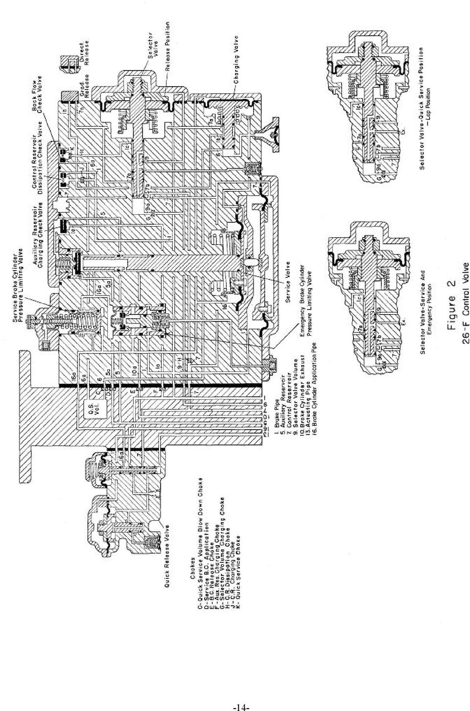
17 A direct or graduated release cap is located on the service portion. Its position is determined by the type of service in which the locomotive is to be used. The selector valve provides a feature that enables the control valve to be satisfactorily trained with D-22 Brake Equipment. It is a diaphragm operated spool valve which functions similarly to a triple valve. With selector volume air pressure on the outer face of the diaphragm opposed by brake pipe pressure on the spring side of the diaphragm, it functions at the start of a brake pipe reduction to produce the quick service function. It also provides the graduated release function with the graduated release cap in Graduated Release position and provides a direct and prompt release with the graduated release cap in Direct Release position. A selector valve overcharge check valve, located in the selector valve exhaust passage and consisting of a spring loaded check valve and vent protector, retains approximately 35 to 45 psi selector volume pressure on the outer face of the selector valve diaphragm during emergency brake applications, making it necessary to first increase brake pipe pressure to the value of the locked-up selector volume pressure value before the release of an emergency brake application can be accomplished. The service portion also contains two brake cylinder pressure limiting valves. One limits the maximum brake cylinder pressure obtained during service brake applications and the other limits the maximum brake cylinder pressure obtained during emergency brake applications, These two limiting valves are arranged in parallel and the emergency brake cylinder pressure limiting valve is held closed by a predetermined brake pipe pressure and is opened to limit the brake cylinder pressure only after the brake pipe pressure is reduced below that value as during emergency brake applications. The setting of the emergency brake cylinder pressure limiting valve is preset by the assembly of parts with no adjustment whereas the setting of the service brake cylinder pressure limiting valve is adjustable. It is set at the test rack and sealed with a sealing wire. This seal shall not be broken except by authorization of the proper railroad personnel. The quick release valve portion of the 26-F Control Valve is designed to permit independent release of the locomotive brake following an automatic brake application developed by the service portion. Upon depressing the independent brake valve handle, air pressure developed in the actuating pipe (No. 13) at the brake valve flows to port No. 13 of the control valve, thus causing the operation of the small diaphragm and spool valve assembly in the quick release valve portion. Movement of this diaphragm and spool valve interrupts and vents to atmosphere the air pressure developed in the service application pipe to the relay valve. Operation of the small diaphragm in the quick release valve portion initiates the operation of the larger diaphragm and spool valve which in turn permits the venting of control reservoir air to the atmosphere in an amount sufficient to equalize the control reservoir pressure with the brake pipe pressure. This prevents reapplication of the brakes upon release of the independent brake valve handle. In order to prevent complete venting of the control reservoir pressure following an emergency brake application and to assure an automatic brake valve brake application immediately following an emergency brake application, a control reservoir pressure retaining check valve is built into the control -15-

18 reservoir exhaust port in place of the wasp excluder employed on earlier versions of the quick release valve portion. This check valve, which also has a vent protector, retains approximately 20 psi control reservoir pressure. Charging Control Valve Operation With the automatic brake valve handle in Release position, brake pipe air flows to the No. 1 connection of the control valve pipe bracket. From port No. 1 the brake pipe air flows to the following passages and chambers: 1. To the chamber above the large diaphragm of the quick release valve. 2. To the spring chamber of the selector valve. 3. To the brake pipe chamber between the two diaphragms in the service valve. 4. To the emergency brake cylinder pressure limiting valve where brake pipe pressure opposes spring pressure to keep the limiting valve spool valve in its downward or closed position. 5. To the chamber above the control reservoir dissipation check valve and also through charging choke J, passage No. 1b, through the charging valve spool valve, to passage No. 7a, and through the selector valve spool valve, passage 7b and choke H, through passage No. 7 to the chamber beneath the service valve diaphragm, and to the Control Reservoir. With the graduated release cap in Direct Release position, passage No. lb is connected directly to passage No. 7a through the cap. 6. Through choke F to the auxiliary reservoir charging check valve through which the auxiliary reservoir is charged. Brake pipe air flowing into passage 7b from the selector valve spool valve also flows through a branch port, past the end of the selector valve spool valve and through passage 9a and choke G and passage No. 9 to the selector valve volume and chamber on the outer face of the selector valve diaphragm. With the brake system fully charged, control reservoir and brake pipe pressures acting on opposite faces of the large diaphragm of the service valve are identical. The service valve piston and diaphragm assembly are, therefore, held in their lowermost position by the tension of the release spring acting' on the diaphragm assembly. The end of the service valve diaphragm stem is drawn away from seating contact with the application and release check valve to allow ports No. 16 and 16a to be exhausted to atmosphere. -16-

19 Service Position When the automatic brake valve handle is moved to Service position, brake pipe pressure in port No. I will be reduced to the degree as determined by amount of brake valve handle movement. This reduction in brake pipe pressure will occur in the chamber above the large service valve diaphragm. The pressure differential caused by the higher control reservoir pressure acting against the outer face of this diaphragm will initiate upward movement of the service valve diaphragm assembly and piston stem to first close the release valve and then to open the application valve. Reduction of brake pipe pressure also occurs in the spring chamber of the selector valve. The resulting pressure differential set up across the selector valve diaphragm moves the diaphragm assembly and spool valve to permit the following to occur: 1. The charging of the selector valve volume from the control reservoir air via choke G is cut off by the spool valve, 2. Quick service action occurs as soon as brake pipe air pressure in the spring chamber has been reduced sufficiently to develop a differential across the selector valve diaphragm sufficient to move the spool valve inwardly to a position where port No. lc is connected to the spring chamber, Then brake pipe air will flow through port No. 1c, choke K, past the back flow check valve and through port No. 6a to the quick service volume in the pipe bracket. The quick service volume air is dissipated through choke C and port No. 6 to atmosphere past the end of the charging valve spool valve. 3. When the selector valve diaphragm and spool valve assembly has moved inwardly to Service position (selector valve stop against body), the selector volume pressure in port No. 9 and acting against the outer face of the selector valve diaphragm assembly is vented to atmosphere via the exhaust port and the selector volume overcharge check valve until the selector volume pressure has become reduced sufficiently to bring about a balance of forces across the diaphragm. The diaphragm assembly and spool valve will then be moved outwardly by spring tension to a Lap position wherein further reduction of selector valve volume pressure is terminated. When the application valve is opened as described above, auxiliary reservoir air in port flows past the unseated application valve and through the service brake cylinder limiting valve to the following chambers: -17-

20 1. To the outer face of the charging valve diaphragm, thus initiating a movement of the charging valve spool valve which cuts off the flow of brake pipe air from the quick service volume to the atmosphere. 2. To port 16 in the pipe bracket via the small diaphragm spool valve in the quick release valve portion and hence through the brake cylinder application (No. 16) pipe to the relay valve. 3. To the large spring chamber in the service valve where pressure will continue to build up until the combined forces of the spring, the air pressure in the spring chamber and the brake pipe pressure will balance the force of the control reservoir pressure acting upwardly on the large diaphragm. Whenever this balance point is approached, the service valve diaphragm assembly and piston stem will be moved downward to assume a Lap position where the application valve has been seated by spring tension and the release valve remains seated. 4. Air pressure in ports No. 16 and 16a builds up on the underside of the service brake cylinder limiting valve until its pressure increases to a point in excess of the adjusted limiting valve spring setting. When this occurs, the spool valve is moved upwardly to a position whereby further flow of air from the application valve to port No. 16 is terminated. The tension of the limiting valve spring thus limits the maximum pressure delivered to the relay valve during a service brake application. Whenever high brake pipe pressures are employed, it is possible to get over-reduction with the 26-F Control Valve; however, an over-reduction will not have any effect upon the brake cylinder pressure since the brake cylinder pressure is determined by the spring loading on the service and emergency brake cylinder limiting valves. Emergency Position When the automatic brake valve handle is moved to Emergency position, the 26-F control Valve functions similarly to that described above; however, several additional features designed into the control valve would be utilized as follows: 1. As during a service brake application, the selector volume pressure reduces through port No. 9 and the selector valve spool valve to atmosphere via the selector volume overcharge check valve. However, selector volume pressure is prevented from being depleted by the spring loading of the selector volume overcharge check valve which will retain approximately 35 to 45 psi. -18-

21 2. The auxiliary (supply) reservoir air flowing past the application valve flows to the brake cylinder limiting valves and into ports No. 16a and 16 and thence to the relay valve. A chamber is provided for brake pipe air in the emergency brake cylinder limiting valve, and it is this pressure that normally holds down the emergency brake cylinder limiting valve spool. During initial stages of an emergency brake application, the emergency brake cylinder limiting valve remains closed. As the brake pipe pressure continues to drop, and is reduced to a value between 10 and 15 psi, the force of the spring within the emergency brake cylinder limiting valve overcomes the force of brake pipe pressure in the spool valve. The spool valve will then be moved upwardly, unseating the check valve, thus providing an alternate passage of auxiliary reservoir air to port No. 16 and the relay valve. During emergency brake applications, the brake pipe pressure drop is so fast that at the time the emergency brake cylinder limiting valve opens the check valve, the service brake cylinder limiting valve is still open and not as yet positioned in its uppermost (closed) position. The check valve in the emergency brake cylinder limiting valve will remain open to permit a continued flow of air to the relay valve. The pressure of the air admitted to the relay valve increases and the service brake cylinder limiting valve will close when its pressure setting is reached. The continued increase of pressure also effects a downward force on the spool valve of the emergency brake cylinder limiting valve, When this pressure reaches a point slightly in excess of the value of the spring within the spool valve, the spool valve will be forced downwardly, permitting the check valve to be seated to terminate further flow of auxiliary (supply) reservoir air to the relay valve. Release Position When the automatic brake valve handle is moved to Release position, the increase in brake pipe pressure causes a similar pressure increase in the brake pipe chamber above the large diaphragm in the service valve. The combined forces of the No. 16 port pressure, brake pipe pressure, and the large release spring, acting against control reservoir pressure move the service diaphragm assembly and piston stem downwardly, drawing the release valve seat out of seating contact with the release check valve face. This permits No. 16 port air to vent to atmosphere from the relay valve through the service valve piston stem to port No. 10 at the pipe bracket. This same air in port No. 16 is also vented from the outer face of the charging valve diaphragm and the spring force will return the charging valve spool valve and diaphragm assembly to its normal or charging position, wherein brake pipe to control reservoir charging is reestablished, especially so if the Graduated Release Cap is positioned for Graduated Release operation. The continued drop of brake cylinder pressure in the brake cylinder limiting valves permits the spring within the service brake cylinder limiting valve to move the valve downward, and, with the buildup of brake pipe pressure, the emergency brake cylinder limiting valve spool valve is also held down. With both valves in their normal downward position, a means for rapid -19-
22 exhaustion of all No. 16 port air is provided. Increase of brake pipe pressure in the selector valve spring chamber to the value of selector volume pressure will move the selector valve spool valve and diaphragm assembly to its normal position, reestablishing charging of the control reservoir and selector volume reservoir to brake pipe pressure. Independent Release Of An Automatic Application When it is desired to release the locomotive brakes independently of the train brakes, the handle of the SA-26 Independent Brake Valve must be depressed in Release position. Main reservoir air will flow into port No. 13 at the control valve via the Actuating Pipe from the brake valve. This air flows through port No. 13 and to the underside of the small diaphragm of the quick release valve portion, where the force overcomes spring force acting against the outer face of the diaphragm and the spool valve and diaphragm assembly are moved to their uppermost position. Control reservoir air may then flow through the spool valve to the underside of the large diaphragm in the quick release portion. The pressure of the control reservoir being higher than the brake pipe pressure acting on the opposite face of the diaphragm positions the spool valve and diaphragm assembly in their uppermost position. With both spool valves in their uppermost position, the air in port No. 16, which is connected to the relay valve, is permitted to ve nt to atmosphere; while the air in the control reservoir and port No. 7 is also permitted to vent to atmosphere. The control reservoir will continue to vent to atmosphere until its pressure has been reduced to approximately that of the brake pipe at which time the pressure differential across the large diaphragm will be reversed and the large diaphragm assembly and spool valve will be forced downward, thus terminating further exhaust of control reservoir air to atmosphere. The decrease of control reservoir air pressure is necessary, since it must be reduced an amount sufficient to equalize with the brake pipe pressure to prevent a re-application of the locomotive brakes upon release of the independent brake valve handle. However, in order to prevent complete depletion of control reservoir pressure when releasing the locomotive brake following an emergency brake application, a control reservoir pressure retaining check valve retains approximately 20 psi control reservoir pressure, the value of its spring loading. The purpose of retaining this control reservoir pressure is to make it possible to immediately obtain an automatic brake on the locomotive following such a release of the locomotive brake after an emergency brake application. J-1 RELAY VALVE The J-1 Relay Valve, Figure 3, is a high capacity, diaphragm operated, self-lapping relay valve consisting of an 0 ring-packed piston stem and a doubleseated rubber check valve. Its purpose is to supply and exhaust brake cylinder air pressure during brake applications and releases. This relay valve is designed to develop in the brake cylinders a pressure approximately equivalent to that developed in the control pipe leading to it. -20-
23 Figure 3 J-1 Relay Valve -21-
24 The operating portion is mounted on a pipe bracket to which all of the pipe connections are made. These are identified as follows: No. 6 - Supply No Control No Delivery (B.C.) During brake applications, air pressure is developed in the line connecting to the No. 16 connection at the relay valve pipe bracket. This air pressure is also developed in the chamber below the large relay valve diaphragm and piston, causing the diaphragm assembly and piston to be moved upwardly. During this upward piston movement, the end of the piston stem, which is formed to contain an exhaust valve seat, first contacts and seals against the underside of the rubber check valve to close the exhaust connection through the piston stem from the delivery (brake cylinder) port No. 30. Further upward movement causes the rubber check valve to be moved off its supply valve seat and main reservoir air is then free to flow past the rubber check valve to port No. 30 and the brake cylinders. Port No. 30 is also connected through a stabilizing choke to the spring chamber on the inner face of the relay valve diaphragm so that as pressure is being developed in the brake cylinders, an equal pressure is being developed in the spring chamber. As the diaphragm becomes balanced, it is moved downwardly to a lap position where the rubber check valve is seated against the supply valve seat to terminate further flow of air to the brake cylinders and the exhaust valve remains seated. The relay valve will function to maintain delivery line (brake cylinder) pressure whenever brake cylinder leakage should cause the pressure to decrease. The pressure in the spring chamber will likewise decrease and the diaphragm assembly and piston stem will again be moved upward by the higher control pressure acting on its outer face. Thus the rubber check valve will be forced off its supply valve seat and main reservoir air will be free to flow to the brake cylinders to restore the pressure lost by leakage. When equalization with control pressure is again reached, the piston and diaphragm assembly will again be moved downward to Lap position, cutting off further flow of main reservoir air to the brake cylinders. Upon brake releases, a reduction in control air pressure acting on the outer face of the relay valve diaphragm will cause the higher brake cylinder pressure to move the diaphragm assembly and piston downward where the exhaust valve seat will be drawn out of seating contact with the rubber check valve. The brake cylinder air is then free to flow past the exhaust check valve seat and through the piston stem to the exhaust port and atmosphere. A graduated release of brake cylinder air pressure may also be obtained whenever the controlled air pressure is intermittently released. Whenever this occurs, the higher brake cylinder pressure causes the diaphragm assembly to operate to open the exhaust until the diaphragm again becomes balanced after which it will again assume its Lap position to close the exhaust. -22-
25 MU-2A VALVE The MU-2A Valve, Figure 4, is a three-position cam-operated spool valve, arranged with a pipe bracket and it is employed to enable a 26-L equipped locomotive to be multiple-united with not only 6 or 26 type equipment but also with a 24-RL equipped locomotive. The MU-2A Valve pilots and F-1 Selector Valve which is a device that enables the equipment of a trailing locomotive to be controlled by the equipment of a lead locomotive in multiple-unit operation. Pipe connections are made at the pipe bracket and they are as follows: 2 Independent Application & Release Pipe (from B.V.) 3 Actuating Pipe (from B.V.) 13 Actuating Pipe 20 Independent Application & Release Pipe 30 Main Reservoir 53 Multiple-Unit Control Pipe 63 Multiple-Unit Interlock Pipe Three escutcheon plate faces are available for use with this valve. Porting arrangement is not affected by the type of escutcheon plate employed. The markings on the three escutcheon plates are as follows: 3 Position 3 Position 2 Position Black Lettering Red Lettering Black Lettering Lead or Dead Lead or Dead Lead or Dead Trail 6-26 Trail Trail 24 Trail Trail The positions of the MU-2A Valve are selected by the positioning of the handle. To do this, the handle must first be depressed to overcome spring loading to permit its being moved. The handle should be positioned with its arrow pointing to whichever position is chosen. Operation The following description covers the operation of the MU-2A Valve when using the 3-Position escutcheon plate with black lettering. Lead or Dead Position With the MU-2A Valve handle in "'LEAD OR DEAD" position, main reservoir air in port No. 30 is blanked by the spool valve, and ports No. 53 and 63 are connected to exhaust. Independent brake control pressure originating at the independent brake valve (port No. 20) is connected to port No. 2 at the MU-2A Valve and through the spool valve -23-
26 Figure 4 MU-2A Valve -24-
27 to port No. 20. Port No. 20 at the MU-2A Valve is connected to port No. 20 of the F-1 Selector Valve where further passage is blanked, and also to the No. 16 connection of the J-1 Relay Valve to provide for independent brake applications on the lead locomotive. The actuating pipe at the brake valve (port No. 13) is connected to port No. 3, at the MU-2A Valve, through the spool valve to port No. 13 in the MU-2A Valve. Port No. 13 is connected to the actuating pipe connection at the 26- F Control Valve and to the trainlined Actuating Pipe if one exists on the locomotive. Trail-6 or 26 Position When a 26-L equipped locomotive is trailed behind a locomotive equipped with 6 or 26 brake equipment, the handle of the MU-2A Valve is positioned in TRAIL-6 or 26 position. The spool valve blanks ports Nos. 2, 3, 13, and 20. Port No. 3, which is connected to the actuating pipe (No. 13 at the brake valve), is exhausted at the independent brake valve with its handle in Release position. Main reservoir air is connected by the spool valve to ports No. 53 and No. 63, which are connected to ports No. 53 and No. 63, respectively, at the F-1 Selector Valve. Thus, the Selector Valve is positioned to allow brake cylinder equalizing pipe air (port No. 14) to be connected to port No. 16 and to port No. 20, both of which are connected through the double check valve to port No. 16 at the J-1 Relay Valve during a brake application initiated from the lead locomotive. Trail-24 Position When a 26-L equipped locomotive is trailed behind a locomotive equipped with 24-RL Brake Equipment, the handle of the MU-2A Valve is positioned in TRAIL-24 position. The spool valve blanks ports Nos. 2, 3, 13, and 20. Port No. 53 is connected to exhaust at the MU-2A Valve. As in TRAIL-6 or 26 position, port 3 is exhausted at the independent brake valve with its handle in Release position. Main reservoir air is connected to port No. 63, which in turn is connected to port No. 63 of the F-1 Selector Valve to position the selector valve to permit brake cylinder equalizing pipe air (port No. 14) to flow to port No. 20, and through the double check valve to port No. 16 at the J-1 Relay Valve during brake applications initiated from the lead locomotive. F-1 SELECTOR VALVE The F-1 Selector Valve, Figure 5, responds to piloting from the MU-2A Valve to condition to the brake equipment on the locomotive to perform satisfactorily as a lead or dead unit, or as a trailing unit in a multiple-unit locomotive. It also performs the function of protecting a trailing locomotive brake equipment by automatically resetting the brake control to LEAD position in the event a separation (break-in-two) between locomotive units. The selector valve portion is mounted on a pipe bracket to which all pipe connections are made and identified as follows: -25-
28 Figure 5 F-1 Selector Valve -26-
29 4 Automatic Brake Control Pipe 12 Emergency Pipe 14 Brake Cylinder Equalizing Pipe 15 Main Reservoir Equalizing Pipe 16 Application Pipe (To Relay Valve) 20 Independent Application & Release Pipe 30 Brake Cylinder Pipe 53 Multiple-Unit Control Pipe 63 Multiple-Unit Interlocking Pipe The F-1 Selector Valve consists of three sections, each consisting of a spool valve. One of them, the protection valve, is controlled by air pressure from the Main Reservoir Equalizing Pipe and in the event of a break-in-two, this spool valve is automatically positioned to provide lead unit braking conditions. The other two, the transfer sections, are controlled by air pressure in the multiple-unit control pipe and the multiple-unit interlocking pipe. Connections are made as shown in the diagrammatic drawings, Figure 5, for the positions LEAD OR DEAD, TRAIL-6 or 26, TRAIL-24 and BREAK-IN-TWO. Lead or Dead Position Operation When a 26-L equipped locomotive is leading a 6 or 26 equipped locomotive air pressure to ports No. 53 and 63 of the F -1 Selector Valve is vented at the MU-2A Valve. Control valve air flowing from connection No. 16 at the 26-F Control Valve flows to connection No. 4 at the Selector Valve where it is connected to connection No. 16 and hence to the locomotive relay valve to develop brake cylinder pressure on the lead locomotive. Brake cylinder air from relay valve connection No. 30 is connected to connection No. 30 at the Selector Valve where it is connected by the spool valve to connection No. 14 and the Brake Cylinder Equalizing Pipe of the lead locomotive for control of the brakes on the trailing locomotive. Trail-6 or 26 Position When a 26-L equipped locomotive is trailing a 6 or 26-L Equipped locomotive, main reservoir air pressure is supplied to connection No. 53 and 63 at the MU-2A Valve to position the spool valves of the F-1 Selector Valve as shown in the diagrammatic as arranged for Trail-6 or 26 position. In this position air from the Brake Cylinder Equalizing Pipe is connected to connection No. 16 and hence to the relay valve to develop brake cylinder pressure. Also brake cylinder equalizing pipe air is connected to connection No. 20 and the Independent Application and Release Pipe which is closed at the MU-2A Valve. Thus, brakes are applied on the trailing unit in the same manner as they are applied on the lead unit. -27-
30 If on a light locomotive the MU-2A Valve is inadvertently placed in this position, the No. 12 pipe will supply air to and position the spool valve to permit a brake valve emergency brake application on the locomotive. Trail-24 Position When a 26-L equipped locomotive is trailing a 24-RL equipped locomotive main reservoir air pressure is supplied to connection No. 63 at the MU-2A Valve to position the spool valve of the F-1 Selector Valve as shown in the diagrammatic as arranged for TRAIL-24 position. In this position, air flowing from connection No. 16 at the 26-F Control Valve flows to connection No. 4 of the F-1 Selector Valve where it is connected to connection No. 16 and hence to the locomotive relay valve to develop brake cylinder pressure. Air pressure also enters Connection No. 14 at the Selector Valve from the Brake Cylinder Equalizing Pipe and flows through the spool valve to connection No. 20. This air pressure also actuates the locomotive relay Valve. The brakes on the trailing locomotive are thus actuated by either an automatic brake application or by an independent brake application initiated at the leading 24- RL equipped locomotive. Break-In-Two Position If a break-in-two occurs and pressure is lost in the Main Reservoir Equalizing Pipe, air is also vented from connection No. 15 of the F-1 Selector Valve and the chamber beneath the protection spool valve (center valve-figure 5) and the spool valve is forced to its lower position by spring tension. Then on a lead locomotive, brake cylinder air flow to the Brake Cylinder Equalizing Pipe (connection No. 14) is cut off by the protection spool valve. On a trailing locomotive where the F-1 Selector Valve is positioned TRAIL6 or 26, the protection spool valve will vent air from the chamber beneath the righthand spool valve which will be forced to its lower position as in the LEAD position to connect ports No. 4 and No. 16. Also at the protection spool valve, port No. 14 to port No. 16 and port No. 20 connection is cut off. If the F-1 Selector Valve is positioned TRAIL-24, the port No. 14 to port No. 20 connection is cut off by the protection spool valve. In either case, control air pressure developed by the 26-F Control Valve is transferred to the relay valve control pipe as it is on a lead locomotive. -28-
31 OVERSPEED CONTROL AND SAFETY CONTROL FUNCTIONS WITH P-2 BRAKE APPLICATION VALVE (Original Application Valve Included With 26-L Brake Equipment Now Superseded By P-2-A) The overspeed control and safety control feature consists of a P-2 Brake Application Valve which is piloted by venting devices comprising an Overspeed Magnet Valve for overspeed control and a Foot Valve for safety control. The Overspeed Magnet Valve is normally energized. Whenever the authorized maximum speed limit is exceeded, the overspeed magnet valve becomes deenergized and it then functions to vent to atmosphere the pressure from the spring chamber of the P-2 Brake Application Valve. Foot pressure must be maintained on the foot pedal of the Foot Valve at all times unless a brake cylinder pressure of approximately 30 psi is already in effect. Whenever foot pressure is removed from the foot pedal, the Foot Valve functions to also vent to atmosphere the pressure from the spring chamber of the P-2 Brake Application Valve. In being vented, the air pressure is dissipated through a system of chokes and whistle, the latter providing an audible warning over a timed delay period before the pressure has become reduced sufficiently to cause the brake application valve to apply. The P-2 Brake Application Valve, Figure 6, functions automatically in response to the operation of overspeed control and safety control venting devices to produce a full service brake application, unless the brake Valve handle has been moved to Suppression position within a predetermined time interval after the start of the audible warning whistle and the speed of the locomotive has been reduced below the overspeed limit (No. 10 pipe venting completed). The P-2 Brake Application Valve, consisting of a main diaphragm controlled spool valve and a suppression valve, is mounted on its pipe bracket to which the pipe connections are made and identified as follows: 3 Foot Valve 5 Equalizing Reservoir 8 Lock Over, Pipe 10 Safety Control Pipe 15 Equalizing Reservoir Charging (From Brake Valve) 25 Power Knock-Out 26 Suppression Pipe 30 Main Reservoir Pipe 24 Reduction Limiting Reservoir With the locomotive equipment charged and operating normally, main reservoir air enters port No. 30 in the pipe bracket, flows to the underside of the diaphragm and also through port No. 10a to the spring chamber above the diaphragm and hence to port No. 10 and to the timing reservoir and Overspeed Magnet Valve which is in its closed -29-
32 Figure 6 P-2 Brake Application Valve -30-
33 (inoperative) position. Main reservoir air from port No. 10 also flows past the lower end of the suppression valve spool valve to port No. 3 and to the Foot Valve which is held closed by foot pressure on the foot pedal. With the chambers on both sides of the diaphragm charged to main reservoir pressure, the diaphragm spring will position the diaphragm assembly and its attached spool valve in their normal or release position. In this position the spool valve makes the following connections: 1. The reduction limiting reservoir volume is exhausted to atmosphere via port 24, and the Power - Knock -Out (P.C.) Switch is vented to atmosphere via port No Equalizing reservoir charging pipe, port No. 15, is connected to the equalizing reservoir pipe, port No. 5. This permits the equalizing reservoir charging air from the brake valve to flow through the application valve and thus charge not only the equalizing reservoir volume but also the equalizing reservoir chamber in the relay valve portion of the brake valve. During a penalty brake application that can be initiated by the venting of the No. 3 pipe through the Foot Valve, or by venting of the No. 10 pipe through the Overspeed Magnet Valve, the air pressure is vented from the spring chamber above the diaphragm faster than it can be restored through the choke in port No. 10a. Consequently, a pressure differential is established across the diaphragm sufficient to cause it and its attached spool valve to be moved upwardly to its application position. In this position, the spool valve makes the following connections: 1. Main reservoir air in port No. 30 and in the chamber beneath the diaphragm is connected to port No. 25 and the Power Knock-Out (P.C.) Switch. 2. Main reservoir air, which normally flows through the choke and port No. 10a is connected to port No. 8. Therefore, the chamber on the spring side of the diaphragm, as well as the timing reservoir volume that is connected to port No. 10, is also integrally connected to port No. 8 which is connected to the lockout (No. 8) pipe between the P-2 Brake Application Valve and Brake Valve. This connection is normally vented at the brake valve by the suppression valve spool valve with the automatic brake valve handle in Release position. 3. Equalizing reservoir charging via port No. 15 is cut off. 4. Equalizing reservoir air in port No. 5 is connected through the spool valve to port No. 24a, through a calibrated choke and thus through port 24 to the Reduction Limiting Reservoir. Equalizing reservoir air is thereby allowed to equalize at a controlled rate -31-
34 with the Reduction Limiting Reservoir to produce a full service equalizing reservoir pressure reduction. A safety control brake application can be suppressed by moving the automatic brake valve handle to Suppression position before the expiration of a predetermined timed delay period after the warning whistle commences to sound. With the brake valve handle in Suppression position, the suppression spool valve at the brake valve is positioned to close the venting of the lock-out (No. 8) pipe, thereby preventing the venting of air from the spring chamber side of the application valve diaphragm through this pipe. Main reservoir air, supplied by the brake valve suppression valve, flows through port No. 26 and connecting pipe to port No. 26 at the P-2 Brake Application Valve where it flows through port No. 26 to the f ace of the suppression valve piston, forcing the piston downwardly to cut off connection between passages No. 3 and No. 10. Thus the spring chamber above the diaphragm is cut off from port No. 3 and the Foot Valve. Main Reservoir air is continuously supplied through port No. 10a and its choke to the spring chamber above the diaphragm, keeping the diaphragm assembly and its attached spool valve in release position. Thus the functioning of the safety control venting devices (Foot Valve) cannot cause the P-2 Brake Application Valve to apply so long as the automatic brake valve handle has been moved to Suppression position. An overspeed control brake application can be suppressed only by reducing the speed of the locomotive below the maximum authorized speed limit before the expiration of the timed delay period after the warning whistle commences to sound. Such action avoids venting the No. 10 pipe through the Overspeed Magnet Valve and the resulting penalty brake application. To reset and release a safety control or overspeed control brake application, the engineman must move the automatic brake valve handle to Suppression position. This results in the closing of the No. 8 pipe venting at the brake valve. The spring chamber above the diaphragm can be re-charged through the choke in port No. 10a to main reservoir pressure. As soon as the pressure in this chamber approaches a predetermined value, the diaphragm assembly and its attached spool valve will be reset to their normal or release position. When the spool valve has been moved to its release position, port No. 15 is again connected to port No. 5 and ports No. 24 and No. 25 are connected to exhaust. Thus, the equalizing reservoir charging connection through the P-2 Brake Application Valve is re-established and the Reduction Limiting Reservoir and Power Cut-Off (P.C.) Switch are vented. To release the brakes, the engineman must next move the automatic brake valve handle to Release position, whereupon re-charging the equalizing reservoir and brake system can be accomplished. -32-
35 Figure 7 P-2-A Brake Application Valve -33-
36 OVERSPEED CONTROL AND SAFETY CONTROL FUNCTIONS WITH P-2-A BRAKE APPLICATION VALVE The overspeed control and safety control feature consists of a P-2-A Brake Application Valve which is piloted by venting devices comprising an Overspeed Magnet Valve for overspeed control and a Foot Valve for safety control. The Overspeed Magnet Valve is normally energized. Whenever the authorized maximum speed limit is exceeded, the overspeed magnet valve becomes de-energized and it then functions to vent to atmosphere the pressure from the spring chamber of the P-2-A Brake Application Valve. Foot pressure must be maintained on the foot pedal of the Foot Valve at all times unless a brake cylinder pressure of approximately 30 psi is already in effect. Whenever foot pressure is removed from the foot pedal, the Foot Valve functions to also vent to atmosphere the pressure from the spring chamber of the P-2-A Brake Application Valve. In being vented, the air pressure is dissipated through a system of chokes and whistles, the latter providing an audible warning over a timed delay period before the pressure has become reduced sufficiently to cause the brake application valve to apply. The P-2-A Brake Application Valve, Figure 7, functions automatically in response to the operation of overspeed control and safety control venting devices to produce a full service brake application, unless the brake valve handle has been moved to Suppression position within a predetermined time interval after the start of the audible warning whistle. The P-2-A. Brake Application Valve, consisting of a main diaphragm controlled spool valve, over reduction check valve, release control valve, and a suppression valve, is mounted on its pipe bracket to which the pipe connections are made and identified as follows: 3 Foot Valve 5 Equalizing Reservoir 8 Lock Over Pipe 10 Safety Control Pipe 15 Equalizing Reservoir Charging (from Brake Valve) 25 Power Knock-Out 26 Suppression Pipe 30 Main Reservoir Pipe 24 Reduction Limiting Reservoir 33 Switch Pipe With the locomotive equipment charged and operating normally, main reservoir air enters port No. 30 in the pipe bracket, flows to the underside of the diaphragm and also through port No. 10a to the spring chamber above the diaphragm and also to port No. 10 to the timing reservoir volume, and overspeed control magnet valve which is in its closed (inoperative) position. Main reservoir air from port No. 10 also flows past the lower end of the suppression valve to port No. 3 and to the Foot Valve which is held closed by foot pressure on the foot pedal. With the chamber on both sides of the diaphragm charged to main reservoir pressure, the diaphragm spring will position the -34-
37 diaphragm assembly and attached spool valve in their normal or release position. In this position the spool valve makes the following connections: 1. The reduction limiting reservoir is exhausted to atmosphere via port No. 24 and the Power Knock-out (P.C.) Switch is vented to atmosphere via port No The equalizing reservoir port No. 5 is connected through to the release control valve to permit charging the equalizing reservoir and equalizing reservoir chamber in the relay valve portion of the brake valve from the equalizing reservoir charging port No. 15. With the automatic brake valve handle in Release position, port No. 33 and the chamber above the release control valve is charged with air at main reservoir pressure and the chambers below the release control valve and application spool valve are vented through port No. 8 and the suppression valve at the brake valve via the No. 8 pipe. Hence, the release control valve is held in its downward position as shown in Figure 7 to connect the No. 5 port with the No. 15 port. During a penalty brake application that can be initiated by the venting of the No. 3 pipe through the Foot Valve or by venting of the No. 10 pipe through the Overspeed Magnet Valve, air pressure is vented from the spring chamber above the diaphragm faster than it can be restored through the choke in port No. 10a. Consequently, a pressure differential is established across the diaphragm sufficient to cause it and its attached spool valve to be moved upwardly to its application position. In this position the spool valve makes the following connections: 1. Main reservoir air in port No. 30 and in the chamber beneath the diaphragm is connected to port No. 25 and thence to the Power Cut- Off (P.C.) Switch and Dynamic Cut-Off Switch. 2. Main reservoir air which normally flows through the choke and port No. 10a is connected to port No. 8. Therefore, the chamber on the spring side of the diaphragm, as well as the timing reservoir volume that is connected to port No. 10, is also integrally connected to port No. 8 which is connected to the lock-out (No. 8) pipe to the brake valve. This pipe is normally vented at the brake valve by the suppression valve spool valve with the automatic brake valve handle in Release position. 3. Equalizing reservoir charging from port No. 15 is cut off. 4. Equalizing reservoir air in port No. 5 is connected through the spool valve to port No. 24a, through a calibrated choke and thus through port No. 24 to the Reduction Limiting Reservoir. Equalizing reservoir air is thereby allowed to equalize at a controlled rate with the Reduction Limiting Reservoir to produce a full service equalizing reservoir pressure reduction. -35-
38 A safety control brake application can be suppressed by moving the automatic brake valve handle to Suppression position before the expiration of the predetermined timed delay period after the warning whistle commences to sound. With the brake valve handle in Suppression position, the suppression valve spool valve at the brake valve is positioned to close the venting of the lock-out (No. 8) pipe, thereby preventing the venting of air from the spring chamber through this pipe. Main reservoir air, supplied by the suppression valve, flows through port No. 26 and connecting pipe to port No. 26 at the P-2-A Brake Application Valve where it flows through port No. 26 to the face of the suppression valve piston, forcing the piston downwardly where its spool valve cuts off connection between ports Nos. 3 and 10. Thus the spring chamber above the diaphragm is cut off from port No. 3 and the Foot Valve. Main reservoir air is continuously supplied through port 10a and its choke to the spring chamber above the diaphragm, keeping the diaphragm assembly and its attached spool valve in release position. Thus, the functioning of the safety control venting device (Foot Valve) cannot cause the application valve to apply so long as the automatic brake valve handle has been moved to Suppression position. An overspeed control brake application can be suppressed only by reducing the speed of the locomotive below the maximum authorized speed limit, before the expiration of the predetermined delay period after the warning whistle commences to sound. Such action avoids venting the No. 10 pipe through the overspeed venting device (Magnet Valve). To reset and release a safety control or overspeed control brake application, the engineman must first move the automatic brake valve handle to Suppression position. This results in the closing of No. 8 pipe venting at the brake 'valve. The spring chamber of the brake application valve will then be recharged through port No. 10a to main reservoir pressure. As soon as the pressure in this chamber approaches a predetermined value, the diaphragm assembly and its spool valve will be reset to their normal or release position. With the brake valve handle in Suppression position, port No. 33 and the chamber above the release control valve is vented through the suppression valve spool valve at the brake valve and, with the No. 8 pipe vent closed, main reservoir air being supplied to port No. 10 is allowed to flow past the application valve spool valve to the chamber beneath the release control valve. The release control valve is, therefore, actuated to cut off the No. 15 to No. 5 port charging. Hence, after the application valve is reset it is necessary to move the automatic brake valve handle to Release position to reset the release control valve to reestablish the equalizing reservoir charging and release of the brakes. An over-reduction can be made if desired after a penalty brake application by moving brake valve handle beyond Service position or the Handle Off position. The over-reduction valve in the P-2-A Brake Application Valve will open to permit equalizing reservoir air to flow from port No. 5 to port No. 15 and the brake valve. -36-
39 BREAK-IN-TWO PROTECTION FEATURE There are two different arrangements of the break-in-two protection feature which can be found on 26-L equipped locomotives. The present standard arrangement employs the A-1 Charging Cut-Off Pilot Valve as the major valvular component. The original arrangement employed two HB-5 Relayair Valves and the description of its operation is included. WITH A-1 CHARGING CUT-OFF PILOT VALVE The break-in-two protection feature employing an A-1 Charging Cut-Off Pilot Valve is shown on diagram, PLATE 2. During normal brake operation the A-1 Charging Cut-Off Valve will be in its normal Release position, Figure 8, and main reservoir air will be present in Chamber A beneath the cut-off piston head to hold it in its upper position as shown. Chamber B beneath the cut-off piston spool valve will be connected to exhaust via port No. 53 and the cut-off pilot valve exhaust in the 26-C Brake Valve on leading units. On trailing units where the cut-off pilot valve is in OUT position, this chamber is charged with main reservoir air. Chamber C above the cut-off piston and port No. 9 is connected to exhaust via the actuating piston spool valve and automatic sanding timing choke. Brake pipe air flows through port No. 1 to Chamber D surrounding the back side of the actuating piston, through the choke in the piston to Chamber E at the outer face of the piston and through port No. 11 to the 90 cu. in. volume reservoir, charging the volume reservoir and both sides of the actuating piston to brake pipe pressure. This piston is, therefore, held in its down position by spring tension as shown. Port No. 35 and the chamber beneath the Dynamic Cut-Out Switch are exhausted through the cut-off piston spool valve. Whenever a break-in-two occurs, brake pipe air pressure drops faster from Chamber D than it can from Chamber E via the choke. The resultant pressure differential across the actuating piston causes it and its spool valve to be moved upwardly against spring tension as shown in the lower view of Figure 8. In this position, main reservoir air is connected through the actuating piston spool valve to Chamber C at the outer face of the cut-off piston and also to port No. 9 and the Power Cut-Off (P.C.) Switch and Sanding Reservoir. With Chamber B beneath the cut-off spool valve normally exhausted, as mentioned above, the presence of main reservoir pressure in Chamber C at the outer face of the cut-off piston will cause the piston and its spool valve to be forced inwardly to its lowermost position, wherein Chamber A beneath the cut-off piston head is then exhausted. In this position, main reservoir air is connected through the cut-off piston spool valve to port No. 35 and to the Dynamic Cut-Off Switch and also past the unseated cut-off check valve to port No. 53 and to the brake pipe cut-off valve in the 26-C Brake Valve. Air pressure in the 90 cu. in. volume reservoir, port No. 11, and Chamber E beneath the actuating chamber continue to reduce to zero through the piston choke -37-
40 Figure 8 A-1 Charging Cut-Off Pilot Valve -38-
41 and port No. 1 to brake pipe exhaust. When this pressure has been reduced to a predetermined value, spring tension will move the actuating piston and its spool valve to its lowermost position as shown in the auxiliary view on Figure 8. Air pressure at the Power Cut-Off Switch and in the Sanding Reservoir will then exhaust through the automatic sanding timing choke via port No. 9 and the actuating piston spool valve. Air pressure likewise exhausts from Chamber C at the outer face of the cut-off piston. In order to reset, the engineman must move the automatic brake valve handle to Emergency position. Main reservoir air is then connected to port No. 12 from the brake valve and flows past the unseated selector check valve to Chamber B beneath the cut-off piston to force the cut-off piston and its spool valve upwardly to their normal release position. The No. 53 pipe, being supplied with air flow from port No. 12, cannot be dissipated through the cut-off pilot valve at the brake valve as is the case with the system employing the two HB-5 Relayair Valves previously described. The brake valve handle must be moved to Release position before the No. 53 pipe air pressure can be drained and then the brakes released. Thus a slight inherent delay in releasing the brakes has been introduced with the use of this arrangement of break-in-two protection. On a trailing unit, main reservoir air is supplied to the No. 53 pipe by the cut-off pilot valve when positioned in OUT" position and, therefore, Chamber B beneath the cut-off piston spool valve is charged to main reservoir pressure. With both Chambers A and B charged to main reservoir pressure, the presence of main reservoir pressure in Chamber C, as supplied through the actuating piston spool valve, does not provide the force to move the cut-off piston inwardly as described for a break-in-two on a lead unit. The P.C. Switch and automatic Sanding are actuated by main reservoir air being supplied to port No. 9. During a manual brake valve emergency brake application on a lead unit, Chamber B beneath the cut-off piston spool valve is charged to main reservoir pressure via port No. 12 and the No. 12 pipe from the automatic brake valve. Thus, with Chambers A, B and C all charged to main reservoir pressure, the cut-off piston and spool valve remain in their upper position as shown in the position diagrammatic on Figure 8. The P.C. Switch and automatic sanding are actuated by main reservoir air flowing through port No. 9. The Dynamic Cut-Out Switch is actuated by main reservoir air supplied directly from the brake valve emergency valve via the No. 12 pipe and No. 24-A Double Check Valve. When it is desired to release the brakes, the brake valve handle should be moved to Release position. There will be an inherent delay, as governed by the time required to exhaust the No. 53 pipe through the cut-off pilot valve, before the brake pipe cut-off valve can open to permit recharging the system and releasing the brakes. WITH TWO HB-5 RELAYAIR VALVES The break-in-two protection employing two HB-5 Relayair Valves is shown on the diagram, PLATE 3. The lower of these HB-5 Relayair Valves is piped into the Brake Pipe in such a manner that, upon a break-in-two, it functions to supply main reservoir air to the outer face of the diaphragm of the upper HB-5 Relayair Valve to -39-
42 Figure 9 HB-5 Relayair Valve -40-
43 actuate it. Main reservoir air is also delivered to the Power Cut-Off (P.C.) and Dynamic Cut-Out Switches and to the sanding circuits. The upper HB-5 Relayair Valve is actuated to supply main reservoir air to pipe and passage No. 53 of the 26-C Brake Valve to close the brake pipe cut-off valve. This relayair valve is "locked" in its applied position until reset by moving the automatic brake valve handle to Emergency position, after which the brakes can be released by moving the brake valve handle to Release position. During normal operation, brake pipe air is fully charged and thus pipes No. 10 and No. 13 to the lower HB-5 Relayair Valve and the 90 cu. in. reservoir are fully charged to position the relayair valve in its normal or release position, as shown in Figure 9. In this position, port No. 11 is connected to port No. 9 which is plugged in this installation, and main reservoir air supply from port No. 12 is cut off by the lower valve. Whenever a break-in-two occurs, the brake pipe pressure drops at a much faster rate in port No. 13 and the spring chamber beneath the diaphragm than it does in the No. 10 pipe and in the chamber above the diaphragm. The resultant pressure differential across the relayair valve diaphragm causes the diaphragm assembly to be forced downwardly, seating the upper valve and unseating the lower valve. In this position, ports No. 11 and No. 12 are connected to permit main reservoir air to flow through port No. 11 and past a 3/8" check valve to the No. 10 connection of the upper relayair valve. This main reservoir air also flows to the Dynamic Cut-Out Switch, to the Power Cut-Off (P.C.) Switch and to the sanding circuit for operation of those devices. With air pressure acting on the outer face of the diaphragm of the upper relayair valve, its lower valve is unseated to permit main reservoir air to flow from port No. 12 to port No. 11 and to the No. 53 connection of the 26-C Brake Valve and thence to the brake pipe cut-off valve via port No. 53 to close it and terminate further brake pipe charging. At the same time main reservoir air flowing from port No. 11 of the upper relayair valve also is banked against the 3/8" check valve and flows to the Dynamic Cut-Out Switch and connection No. 10 of the relayair valve. Port No. 53 in the automatic brake valve is connected to exhaust through the spool valve of the cut-off valve and provides an audible warning that a break-in-two has occurred and that the automatic brake valve handle should be moved to Emergency position. After brake pipe pressure has exhausted completely from the 90 cu. in. volume reservoir and the No. 10 pipe at the lower HB-5 Relayair Valve, the force of the diaphragm spring will move the diaphragm assembly upwardly to allow the relayair valve to reset itself, thus seating the lower valve and unseating the upper valve. This terminates further flow of main reservoir air through the lower relayair valve to the upper relayair valve. However, the upper relayair valve remains in its applied position and main reservoir air supplied through it continues to hold it in applied position, wherein main reservoir air continues to flow to the brake pipe cut-off valve in the 26-C Brake Valve and to the Dynamic Cut-Off Switch. In order to reset the upper HB-5 Relayair Valve after a break-in-two operation, the engineman must move the automatic brake valve handle to Emergency position. Main reservoir air is then connected to the No. 12 pipe from the brake valve and flows to the No. 13 connection of the HB-5 Relayair Valve and through port No. 13 to the spring chamber beneath the diaphragm assembly. As soon as air pressure is balanced across the diaphragm, the diaphragm spring will force the diaphragm assembly upwardly to close the No. 12 to No. 11 connection through the relayair valve, thus -41-
44 terminating further flow of main reservoir air to the No. 53 connection of the 26-C Brake Valve and the brake pipe cut-off valve. Air pressure in the No. 53 pipe and behind the brake pipe cut-off valve as well as that in the No. 10 pipe between the relayair valve diaphragm and 3/8" check valve is then dissipated by venting through the cut-out pilot valve exhaust. The brakes can then be released and the system can be recharged by moving the automatic brake valve handle to Release position after the break-in-two has been repaired. DYNAMIC BRAKE INTERLOCK FEATURE The dynamic brake interlock feature functions during dynamic braking to release or prevent an automatic service brake application on the locomotive. It consists of an FB-4 Magnet Valve installed in the brake system between the main reservoir supply to the 26-C Brake Valve and the No. 13 (Actuating Pipe) connection to the 26-F Control Valve as shown on Plate 8 in the back of this pamphlet. The magnet valve consists of two opposed check valves, a coil, and an armature. Its coil has two wire connections which are connected into the dynamic brake electric circuit. Referring to Plate 8, the coil of the FB-4 Magnet Valve is normally deenergized. Its upper check valve is, therefore, unseated to vent the No. 13 (Actuating Pipe) to atmosphere by connecting its pipe bracket connections Nos. 1 and 3. Its lower check valve is seated by spring tension to cut off main reservoir air supply from pipe bracket connection No. 2 to connection No. 1 and the actuating pipe to the 26-F Control Valve. Upon the initiation of a dynamic brake operation, the dynamic brake circuit is conditioned to energize the coil of the magnet valve. The coil armature then seats the upper check valve to cut off the No. 13 pipe to atmosphere connection and unseats the lower check valve to permit main reservoir air to flow to the quick release portion of the control valve via the Actuating Pipe to release an automatic brake or to prevent the development of an automatic brake on the locomotive so long as dynamic braking is in effect. Independent application and release of the locomotive brake is available at all times, irrespective of dynamic brake operation. During any emergency brake application, the dynamic brake is nullified, allowing the automatic pneumatic brake to operate. This is accomplished through the use of a Dynamic Cut-Out Switch suitably installed to de-energize the FB-4 (Dynamic Interlock) Magnet Valve during emergency brake operations. Also, some equipments are arranged to permit dynamic brake nullification during safety control and overspeed control brake applications. -42-
45 AUTOMATIC SPLIT REDUCTIONS DURING PENALTY BRAKE APPLICATIONS WITH A-1 REDUCTION SELECTOR VALVE PLATE 11 The A-1 Reduction Selector Valve is a device that, when used with a P-2-A Brake Application Valve and a First Suppression Reservoir and its associated cut-out cock as an adjunct to the basic 26-L Brake Equipment, functions to produce a split reduction during a penalty brake application. The cut-out cock used in conjunction with the First Suppression Reservoir is a plug type having an escutcheon plate designating its two handle positions; namely, FRT. (open), and PASS. (closed). With the cut-out cock handle in FRT. position, the First Suppression Reservoir is cut in to provide the split reduction and with the cut-out cock handle in PASS. Position, the reservoir is cut out and a straight-away reduction results. The First Suppression Reservoir contains a volume of air at brake pipe pressure, whenever the equipment is conditioned for freight service, the venting of which over a predetermined time period provides the first part of the split reduction during the penalty brake application. The manner in which the A-1 Reduction Selector Valve and its associated devices are piped into the basic 26-L Brake Equipment is shown on Plate 11. Referring to Figure 10, the A-1 Reduction Selector Valve consists of a charging valve portion and a split reduction valve portion mounted on a common pipe bracket to which all pipe connections are made and identified as follows: 1. Brake Pipe 3. Switch Pipe 10. Application Pipe (Blanked) 15. Equalizing Reservoir Charging Pipe 17. Brake Pipe Exhaust (Blanked) 23. First Suppression Reservoir 24. Reduction Limiting Reservoir 25. Power Knockout 26. Suppression Pipe 41. Suppression Gage Connection (Blanked) 42. Stop Reservoir (Blanked) The charging valve portion permits the charging of the First Suppression Reservoir so long as its associated cut-out cock is positioned for freight service and the automatic brake valve handle is in Release position. During brake valve initiated brake applications, the reservoir volume is exhausted to atmosphere past the charging valve to insure that if a penalty brake application should be initiated on top of a brake valve application, the automatic split reduction feature will be nullified and a straightaway reduction will be the result. -43-
46 Figure 10 Diagrammatic A-1 Reduction Selector Valve -44-
47 The split reduction valve portion functions during penalty brake applications to first terminate charging of the First Suppression Reservoir and then to employ this volume of air to divide the equalizing reservoir pressure reduction into two distinct stages, the first of which results in approximately a 7 to 8 psi reduction before commencing the second or last stage when the reduction will continue until the brake valve handle is moved to Suppression position. Release and Charging Operation With the 26-C Brake Valve handle in Release position and the handle of the cut-out cock in the pipe line to the First Suppression Reservoir set in (FRT.) position, main reservoir air flows from port No. 3 in the brake valve to port No. 3 in the A-1 Reduction Selector Valve and to the chamber beneath the charging valve spool valve to position this valve in its uppermost position as shown in Figure 10. Brake pipe air flows to port No. 1 in the reduction selector valve pipe bracket from where it flows through the charging valve spool valve to port No. 22 and to the split reduction spool valve. Spring tension holds the split reduction spool valve in its lowermost position, connecting ports Nos. 22 and 23, thereby charging the First Suppression Reservoir to brake pipe pressure. Port No. 15, being connected to the Equalizing Reservoir Charging Pipe from the 26-C Brake Valve and P-2-A Brake Application Valve, is charged to equalizing reservoir pressure. Port No. 26, being connected to port No. 26 at the 26-C Brake Valve and P-2-A Brake Application Valve, is vented with the brake valve handle in Release position. Ports Nos. 24 and 25 are connected to ports Nos. 24 and 25, respectively, at the P-2-A Brake Application Valve and are at atmospheric pressure with no penalty brake application in effect. Penalty Brake Application Actuation of the P-2-A Brake Application Valve by the functioning of the overspeed control or safety control venting devices will cause the A-1 Reduction Selector Valve to split the equalizing reservoir reduction. Air from the No. 25 port in the P-2-A Brake Application Valve will flow through port No. 25 in the A-1 Reduction Selector Valve to the underside of the split reduction spool valve thus moving the spool valve against spring tension to its uppermost position. In this position of the spool valve, charging of the First Suppression Reservoir is terminated and air from this reservoir volume is connected via port No. 31 to the chamber beneath the split reduction diaphragm valve. The split reduction diaphragm valve spool valve is moved upwardly, closing the connection between ports Nos. 24 and 24b. Equalizing reservoir air equalizes into the confined No. 24 pipe volume (reduction limiting reservoir) between the P-2-A Brake Application Valve and the split reduction diaphragm valve of the A-1 Reduction Selector Valve to produce the first step of a split reduction. This No. 24 pipe between the two valvular devices must be of a specified length depending upon its pipe size so as to -45-
48 provide a volume that will produce an initial equalizing reservoir reduction of approximately 7 to 8 psi. The split reduction diaphragm valve is held in its uppermost position until the pressure in the First Suppression Reservoir volume has been reduced to a sufficiently low value by venting to atmosphere through a calibrated choke in the diaphragm cover, to cause spring tension to move the valve to its lowermost position, re-establishing connection between ports Nos. 24 and 24b. When this occurs, the second or final step of the split reduction is accomplished by continued exhausting of equalizing reservoir air to atmosphere at a service rate via ports No. 24 and 24b and past the end of the reduction limiting valve to produce a full service brake application. A minimum reduction (first part of split reduction) following a penalty brake application cannot be avoided. However, a full service brake application may be avoided by moving the automatic brake valve handle to Suppression position before the expiration of approximately 20 seconds after the initiation of the penalty brake application. This 20 seconds is the approximate delay time before the start of the second part of a split reduction. Movement of the brake valve handle to Suppression position permits air at main reservoir pressure to flow from port No. 26 at the brake valve to and through port No. 26 at the A-1 Reduction Selector Valve, causing the reduction limiting valve to be moved against spring tension to its uppermost position to close off the exhaust of equalizing reservoir air from port No. 24b. Also, with the brake valve handle in Suppression position, air is exhausted from port No. 3, allowing the charging valve to be moved downward by spring tension. This closes the brake pipe port No. 1 at the charging valve and exhausts port No. 22. If the P-2-A Brake Application Valve is reset within the delay time, the split reduction spool valve will re-establish the port No. 23 to port No. 22 connection as a result of venting air from port No. 25 and the underside of the spool valve via the spool valve in the P-2-A Brake Application Valve. The air in the First Suppression Reservoir is then exhausted past the upper end of the charging valve via port No. 22. Equalizing reservoir air in port No. 24 is also exhausted at the spool valve of the brake application valve. Port No. 5 and the Equalizing Reservoir are bottled up at the release control valve in the brake application valve. Immediately following reset of the P-2-A Brake Application Valve, movement of the brake valve handle to Release position will actuate the release control valve to re-establish the port No. 15 to port No. 5 connection within the brake application valve to permit a running release of the brakes. If the P-2-A Brake Application Valve does not reset within the delay time period, the entire supply of air in the First Suppression Reservoir will have been exhausted through the timing choke located in the cover beneath the split reduction diaphragm valve. This valve will then be moved downward by spring tension to re-establish the port No. 24 to port No. 24b connection around its spool valve. -46-
49 Since the brake valve handle was placed in Suppression position, equalizing reservoir air cannot vent to atmosphere past the upper end of the reduction limiting valve. However, equalizing reservoir air in port No. 24b can flow past the light spring loaded differential check valve and into port No. 15 since air pressure in that port has been reduced approximately 24 psi with the brake valve handle in Suppression position. Equalizing reservoir air can therefore flow into the equalizing reservoir charging line with the result that a full service brake application will be insured during a penalty brake application. Should it become necessary, an over-reduction can be made following a split reduction by moving the automatic brake valve handle further towards Handle Off position wherein the equalizing reservoir charging port No. 15 is exhausted at the brake valve beyond the full service reduction to zero in the Handle-Off position. So long as the P-2-A Brake Application Valve has not been reset, equalizing reservoir air in port No. 5 at the brake application valve will flow through port Nos. 24 and 24b in the A-1 Reduction Selector Valve, past the differential check valve and into the equalizing reservoir charging port No. 15 and thence to the brake valve exhaust. If the P-2-A Brake Application Valve has reset, this function will be nullified at the A-1 Reduction Selector Valve, but will be taken over by the over-reduction check valve located in the P-2-A Brake Application Valve. If a penalty brake application is initiated on top of a brake valve service brake application, there will be no split reduction because port No. 3 having been exhausted at the brake valve permits the exhausting of air from the First Suppression Reservoir past the charging valve in the A-1 Reduction Selector Valve. Equalizing reservoir air will then exhaust to atmosphere past the reduction limiting valve via ports Nos. 24b and
50 AUTOMATIC SPLIT REDUCTIONS DURING PENALTY BRAKE APPLICATIONS AND TEMPORARY SUPPRESSION OF OVERSPEED CONTROL APPLICATIONS WITH A-2 REDUCTION SELECTOR VALVE PLATE 12 The A-2 Reduction Selector Valve, Figure 11, is a device that when used with a P-2-A Brake Application Valve and a First Suppression Reservoir and its associated cutout cock as an adjunct to the basic 26-L Brake Equipment, functions to produce a split reduction during penalty brake applications and also provides temporary suppression of overspeed penalty brake applications. The cut-out cock used in conjunction with the First Suppression Reservoir is a plug type having an escutcheon plate designating its two handle positions; namely; FRT. (open) and PASS. (closed). With the cut-out cock handle in FRT. position, the First Suppression Reservoir is cut in to provide split reduction and with the cut-out cock handle in PASS. position, the reservoir is cut out and a straightaway reduction results. The First Suppression Reservoir contains a volume of air at brake pipe pressure whenever the equipment is conditioned for freight service, the venting of which over a predetermined period of time provides the first part of the split reduction during the penalty brake application. The manner in which the A-2 Reduction Selector Valve and its associated devices are piped into the basic 26-L Brake Equipment is shown on Plate 12. The A-2 Reduction Selector Valve consists of a suppression valve portion and a split reduction valve mounted on a common pipe bracket to which all pipe connections are made and identified as follows: 1 Brake Pipe 3 Switch Pipe 10 Application Pipe 15 Equalizing Reservoir Charging Pipe 17 Brake Pipe Exhaust (To Brake Valve Port X" 23 First Suppression Reservoir 24 Reduction Limiting Reservoir 25 Power Knockout 26 Suppression Pipe 41 Suppression Gage Pipe 42 Stop Reservoir The suppression valve portion contains the charging valve which permits the charging of the First Suppression Reservoir volume so long as its associated cut-out cock is positioned for freight service and the automatic brake valve handle is in Release position. The charging valve also functions to exhaust the air from the First Suppression Reservoir during brake valve initiated brake applications to insure that, if a penalty -48-
51 -49-
52 brake application is initiated on top of a manual brake application, the split reduction feature will be nullified. The suppression valve portion also contains the suppression valve which provides temporary suppression of an overspeed brake application. The split reduction valve portion is the same as that portion employed on the A-1 Reduction Selector Valve and described in the preceding section. It functions during penalty brake applications to first terminate charging of the First Suppression Reservoir and then to employ this volume of air to divide the equalizing reservoir reduction into two distinct stages, the first of which results in approximately a 7 to 8 psi reduction before the commencing of the second or last stage when the reduction will continue until the brake valve handle is moved to Suppression position. Release and Charging Operation With the 26-C Brake Valve handle in Release position and the handle of the cut-out cock in the pipe line to the First Suppression Reservoir set in freight (FRT.) position, main reservoir air flows from port No. 3 in the brake valve to port No. 3 in the A-2 Reduction Selector Valve and to the chamber beneath the charging valve spool valve to position this valve in its uppermost position as shown in Figure 11. Brake pipe air flows to port No. 1 in the reduction selector valve pipe bracket from where it flows through the charging valve spool valve to port No. 22 and to the reduction spool valve. Spring tension holds the split reduction spool valve in its lowermost position, connecting ports Nos. 22 and 23, thereby charging the First Suppression Reservoir to brake pipe pressure. Port No. 15, being connected to the Equalizing Reservoir Charging Pipe from the 26-C Brake Valve and the P-2-A Brake Application Valve, is charged to equalizing reservoir pressure. Port No. 26, being connected to port No. 26 at the 26-C Brake Valve and the P-2-A Brake Application Valve, is exhausted to atmosphere at the brake valve suppression valve. Ports Nos. 24 and 25 are connected to ports Nos. 24 and 25 respectively at the P-2-A Brake Application Valve and are at atmospheric pressure with no penalty brake application in effect. The suppression valve spool valve in the suppression valve portion is held in its uppermost position by spring tension and connects ports Nos. 10 and 42. Thus, the application pipe No. 10 from the P-2-A Brake Application Valve is connected through the suppression valve spool valve to the Overspeed Magnet -50-
53 Valve via port No. 42 and the H-5-A Relayair Valve which is normally open so long as the brake valve has not been cut out as on a trailing unit. Port No. 17 which leads to one side of a double check valve in the suppression valve portion is connected to port X (brake valve exhaust port) at the relay valve portion of the 26-C Brake Valve and is vented to atmosphere with the brake valve handle in Release position. The chamber on the opposite side of the double check valve is exhausted through the choke located in the cover, as is the spring chamber of the charging valve. Penalty Brake Applications Actuation of the P-2-A Brake Application Valve by the functioning of the overspeed control or safety control venting devices will cause the A-2 Reduction Selector Valve to split the equalizing reservoir reduction. Air from the No. 25 port in the P-2-A Brake Application Valve will flow through port No. 25 in the A-2 Reduction Selector Valve to the underside of the split reduction spool valve, thus moving the spool valve against spring tension to its uppermost position. Also air will flow from port No. 25 to the outer face of the suppression valve diaphragm to prevent suppression of the application after it has been initiated by the P-2-A Brake Application Valve. In this position of the spool valve, charging of the First Suppression Reservoir is terminated and air from this reservoir volume is connected via port No. 31 to the chamber beneath the split reduction diaphragm valve. The split reduction diaphragm valve spool valve is moved upwardly, closing the connection between ports Nos. 24 and 24b. Equalizing reservoir air equalizes into the confined No. 24 pipe volume (reduction limiting reservoir) between the P-2-A Brake Application Valve and the split reduction diaphragm valve of the A-2 Reduction Selector Valve to produce the first step of a split reduction. This No. 24 pipe between the two valvular devices must be of specific length depending upon its pipe size so as to provide a volume that will produce an initial equalizing reservoir reduction of approximately 7 to 8 psi. The split reduction diaphragm valve is held in its uppermost position until the pressure in the First Suppression Reservoir volume has been reduced to a sufficiently low value by venting to atmosphere through a calibrated choke in the diaphragm cover, to cause spring tension to move the valve to its lowermost position, re-establishing connection between ports Nos. 24 and 24b. When this occurs, the second or final step of the split reduction is accomplished by continued exhausting of equalizing reservoir air to atmosphere at a service rate via ports Nos. 24 and 24b and past the end of the reduction limiting valve to produce a full service brake application. A minimum reduction (first part of split reduction) following a penalty brake application cannot be avoided. However, a full service brake application may be avoided by moving the automatic brake valve handle to Suppression position before the expiration of approximately 20 seconds after the initiation of the penalty brake application. This 20 seconds is the approximate delay time before the start of the second part of the split reduction. Movement of the brake valve handle to Suppression position permits air at main reservoir pressure to flow from port No. 26 at the brake valve to and through port No. 26 at the A-2 Reduction Selector Valve, causing the reduction limiting valve to be -51-
54 moved against spring tension to its uppermost position to close off the exhaust of equalizing reservoir air from port No. 24b. Also, with the brake valve handle in Suppression position, air is exhausted from port No. 3, allowing the charging valve to be moved downwardly by spring tension. This closes the brake pipe port No. 1 at the charging valve and exhausts port No. 22. If the P-2-A Brake Application Valve is reset within the delay time, the split reduction spool valve will reestablish the port No. 23 to port No. 22 connection as a result of venting air from port No. 25 and the underside of the spool valve via the spool valve in the P-2-A Brake Application Valve. The air in the First Suppression Reservoir is then exhausted past the upper end of the charging valve via port No. 22. Equalizing reservoir air in port No. 24 is also exhausted at the spool valve of the brake application valve. Port No. 5 and the Equalizing Reservoir are bottled up at the release control valve in the brake application valve. Immediately following resetting of the P-2-A Brake Application Valve, movement of the brake valve handle to release position will actuate the release control valve to reestablish the port No. 15 to port No. 5 connection within the brake application valve to permit a running release of the brakes. If the P-2-A Brake Application Valve does not reset within the delay time period, the entire supply of air in the First Suppression Reservoir will have been exhausted through the timing choke in the cover beneath the split reduction diaphragm valve. This valve will then be moved downwardly by spring tension to reestablish the port No. 24 to port No. 24b connection. Since the brake valve handle was placed in Suppression position, equalizing reservoir air cannot vent to atmosphere past the upper end of the reduction limiting valve from port No. 24b. However, equalizing reservoir air in port No. 24b can flow past the light spring loaded differential check valve and into port No. 15 since air pressure in that port has been reduced approximately 24 psi with the brake valve handle in Suppression position. Equalizing reservoir air can therefore flow into the equalizing reservoir charging line with the result that a full service brake application will be insured during a penalty brake application. If a penalty brake application is initiated on top of a brake valve service brake application, the split reduction feature is lost because, due to venting of port No. 3, the First Suppression Reservoir will have been vented to atmosphere via the charging valve and choke in the cover. Equalizing reservoir air in port Nos. 24 and 24b will reduce at a service rate past the reduction limiting valve. Temporary Suppression Of Overspeed Control Application With the equipment fully charged and conditioned for freight service (First Suppression Reservoir cut in), making a light brake application with the brake valve before the expiration of the warning period prior to application of the P-2-A Brake Application Valve permits temporary suppression of an overspeed penalty brake application. Moving the brake valve out of Release position vents air from passage No. 3 of the A-2 Reduction Selector Valve, causing the charging valve to first terminate -52-
55 charging of the First Suppression Reservoir and then to connect the reservoir volume through passages Nos. 23 and 22 to the choke in the cover and to the chamber above the double check valve in the suppression valve portion. Pressure above the double check valve holds the valve down, thus permitting the air from the First Suppression Reservoir to flow not only to port No. 41 which is connected to the Suppression Gage, but also to the chamber above the suppression valve diaphragm. At such time when sufficient pressure is developed in port No. 41 and on the upper face of the suppression valve diaphragm, the suppression valve will be moved downwardly against spring tension to cut off port No. 10 from port No. 42. It must be. remembered, however, that air in the chamber above the suppression valve diaphragm is being vented through the choke in the cover. The blowdown time of the air in the First Suppression Reservoir through this choke is approximately 20 seconds. Since the brake valve handle is placed in the service zone of application, the brake pipe air that is exhausted at the relay portion of the brake valve (port "X") flows through a connecting pipe to and through port No. 17 at the A-2 Reduction Selector Valve. Since air pressure in port No. 17 is now greater than that in port No. 22, the double check valve will be moved to its uppermost position and air in port No. 17 can then flow to the chamber above the suppression valve diaphragm, holding the diaphragm assembly in its lowermost position to close off the port No. 42 to port No. 10 connection. Air in port 17 is also being exhausted to atmosphere through a calibrated choke in the relay portion of the automatic brake valve. Therefore, successive light brake applications should be made in order to permit the air from the First Suppression Reservoir to position the suppression valve down and the air in port No. 17 will add to this supply to position the double check valve upwardly and momentarily maintain the suppression valve in its down position. This entire function provides for temporary suppression. With the brake valve handle in the service zone of application, a braking force will be applied to the locomotive. If this braking force is not sufficient to slow the locomotive speed to the allowable speed in order to deenergize the overspeed magnet valve, successive light brake applications are required. If the locomotive speed is not reduced to that allowed, air in port No. 17 and in the chamber above the suppression valve diaphragm would have been exhausted to atmosphere at the brake valve. The suppression valve assembly will then be moved upwardly by spring tension and the port No. 42 to port No. 10 connection will be reestablished. Air in the No. 10 pipe can then exhaust to atmosphere via the overspeed magnet valve. In passenger service, the First Suppression Reservoir is cut out by positioning of its associated cut-out cock and split reduction brake applications and temporary suppression of overspeed control penalty brake applications cannot be obtained. -53-
56 AUTOMATIC SPLIT REDUCTIONS DURING PENALTY BRAKE APPLICATIONS AND TEMPORARY AND PERMANENT SUPPRESSION OF TRAIN CONTROL BRAKE APPLICATION WITH C-1 SUPPRESSION VALVE PLATE 13 The C-1 Suppression Valve, Figure 12, is a device that when used with a P-2-A Brake Application Valve, a First Suppression Reservoir and its associated cut-out cock, an H-5-A Relayair Valve, a Stop Reservoir and a Te mporary Suppression Volume Reservoir as an adjunct to the basic 26-L Brake Equipment, functions to provide a split reduction during penalty brake applications in freight service. It also provides temporary and permanent suppression of train control brake applications in both freight and passenger service. The cut-out cock used in conjunction with the First Suppression Reservoir is a plug type having an escutcheon plate designating its two handle positions; namely, FRT. (open), and PASS. (closed). With the cut-out cock handle in FRT. position, the First Suppression Reservoir is cut in to provide the split reduction and with the handle in PASS. position, the reservoir volume is cut out resulting in a straight-away reduction during penalty brake applications. The First Suppression Reservoir contains a volume of air at brake pipe pressure whenever the equipment is conditioned for freight service, the venting of which over a predetermined period of time provides the time delay between the start of the first and second stages of the split reduction. The manner in which the C-1 Suppression Valve and its associated devices are piped into the basic 26-L Brake Equipment is shown on Plate 13. The C-1 Suppression Valve consists of a suppression valve portion and a split reduction valve portion mounted on a common pipe bracket to which all pipe connections are made and identified as follows: 1. Brake Pipe 2. Temporary Suppression Volume Reservoir 3. Switch Pipe 6. Timing Valve Pipe 8. Lockover Pipe 15. Equalizing Reservoir Charging Pipe 17. Brake Valve Exhaust 23. First Suppression Reservoir 24. Reduction Limiting Reservoir 25. Power Knockout 26. Suppression Pipe 41. Suppression Gage Pipe 42. Stop Reservoir -54-
57 -55-
58 The suppression valve portion contains the charging valve, which functions in the same manner as it does in the A-1 and A-2 Reduction Selector Valves to permit charging of the First Suppression Reservoir so long as the associated cut-out cock is positioned for freight service and the automatic brake valve handle is in Release position. The charging valve also functions to exhaust air from the First Suppression Reservoir during brake valve initiated brake applications to insure that, if a penalty application is initiated on top of a manual brake Application, the split reduction feature will be nullified. The suppression valve portion also contains a temporary suppression valve which permits temporary suppression of a train control application in response to making light brake applications at the brake valve, and a permanent suppression valve which permits permanent suppression of a train control brake application when the brake valve handle has been moved to Suppression position. The split reduction valve portion is the same as employed on the A-1 and A-2 Reduction Selector Valves described in the previous sections of this pamphlet. It functions during penalty brake applications to first terminate charging of the First Suppression Reservoir and then to employ this volume of air to split the equalizing reservoir reduction into two distinct stages, the first of which results in approximately a 7 to 8 psi reduction before the start of the second stage when the reduction will continue at a service rate until the brake valve handle is moved to Suppression position. Release and Charging Operation With the 26-C Brake Valve handle in Release position and the handle of the cutout cock in the pipe line to the First Suppression Reservoir set in freight (FRT.) position, main reservoir air flows from port No. 3 in the brake valve to port No. 3 in the C-1 Suppression Valve and to the chamber beneath the charging valve spool valve to position this valve in its uppermost position as shown in Figure 12. Brake pipe air flows to port No. 1 in the C-1 Suppression Valve pipe bracket from where it flows through the connection made by the charging valve spool valve to port No. 22 and to the split reduction spool valve. Spring tension holds the split reduction spool valve in its lowermost position connecting ports Nos. 22 and 23, thereby permitting the charging of the First Suppression Reservoir to brake pipe pressure. Brake pipe air in port No. 1 also flows to the spring chamber beneath the temporary suppression valve diaphragm, to the spillover check valve and to the suppression spool valve. Brake pipe air also flows from the charging valve past the charging check valve to the chamber above the temporary suppression valve diaphragm, to the temporary suppression valve check valve and also through port No. 2 to the Temporary Suppression Volume Reservoir, charging it to approximately brake pipe pressure. With brake pipe pressure acting on both sides of the temporary suppression valve diaphragm, spring tension holds the valve and stem in its uppermost position. -56-
59 Port No. 15, being connected to the Equalizing Reservoir Charging Pipe from the 26-C Brake Valve and the P-2-A Brake Application Valve, is charged to equalizing reservoir pressure. Port No. 26 being connected to port No. 26 at the 26-C Brake Valve and the P-2-A Brake Application Valve, is exhausted to atmosphere at the brake valve suppression valve. The reduction limiting valve and the suppression spool valve are, therefore, held in their release position by spring tension as shown. Ports Nos. 24 and 25 are connected to ports Nos. 24 and 25 respectively at the P-2-A Brake Application Valve and, with no penalty brake application in effect, are vented of any pressure. The split reduction spool valve and the permanent suppression valve are, therefore, held in release position by spring tension as shown. Port No. 6 is connected to port No. 5 of the train control timing valve and is vented at the timing Valve in the absence of a train control brake application. Port No. 42, which is connected to the Stop Reservoir, being connected to port No. 6 by the permanent suppression valve spool valve, is likewise vented. Port No. 8, being connected to port No. 8 at the 26-C Brake Valve and P-2-A Brake Application Valve is vented at the brake valve suppression valve with the brake valve handle in Release position. Port No. 17 is connected to the brake pipe service exhaust port (port "X" at the relay valve of the 26-C Brake Valve. With the brake valve handle in Release position, this port is vented. Port No. 41 is connected to the Suppression Gage Pipe and is vented to atmosphere through the temporary suppression valve piston stern. Penalty Brake Applications Actuation of the P-2-A Brake Application Valve by reason of a train control function is caused by the actuation of the train control timing valve by a track signal to permit No. 10 pipe air to flow from the brake application valve to port No. 6 of the C-1 Suppression valve via the timing valve. Upon application of the P-2-A Brake Application Valve, air from its port No. 25 flows through port No. 25 in the C-1 Suppression Valve to the underside of the split reduction spool valve and to the lower face (spring side) of the diaphragm of the permanent suppression valve. The split reduction valve is moved upwardly against spring tension where charging of the First Suppression Reservoir is terminated and the reservoir volume is connected via port No. 31 to the chamber beneath the split reduction diaphragm valve. The split reduction diaphragm valve spool valve is held in its upper position approximately 20 seconds duration which is the time required for the volume of air to vent through the Calibrated choke in the cover. With the split reduction diaphragm valve in its uppermost position, the port No. 24 to port No. 24-b connection is cut-off. The permanent suppression valve is held in its uppermost position to permit air from port -57-
60 No. 6 (No. 10 pipe air from the P-2-A Brake Application Valve) to flow through port No. 42 to the Stop Reservoir and also past the back flow check valve and through port No. 8 to the exhaust at the suppression valve of the 26-C Brake Valve. Equalizing reservoir air flows into port No. 24 of the C-1 Suppression valve, equalizing with the confined No. 24 pipe volume (reduction limiting reservoir) between the P-2-A Brake Application Valve and the split reduction diaphragm valve to provide the first stage of the split reduction. This No. 24 pipe between the two valvular devices must be of a specific length, dependent upon its pipe size, so as to provide a volume that will produce an initial equalizing reservoir reduction of approximately 7 to 8 psi. After the pressure in the First Suppression Reservoir has reduced to a predetermined amount by venting through the choke in the cover, spring tension will move the split reduction diaphragm valve downwardly to reestablish the port 24 to port 24b connection and then equalizing reservoir pressure reduction will continue by venting to atmosphere via port 24b and past the reduction limiting valve. This reduction, which is the second stage of the split reduction will continue at a service rate until the brake valve handle is moved to Suppression position. A minimum reduction (first part of a split reduction) following a penalty brake application cannot be avoided. However, a full service brake application may be avoided by moving the automatic brake valve handle to Suppression position in time to reset the P-2-A Brake Application Valve before the expiration of approximately 20 seconds after the initiation of the penalty brake application. This 20 seconds is the approximate delay time before the start of the second stage of the split reduction. Movement of the brake valve handle to Suppression position permits air at main reservoir pressure to flow from port No. 26 at the brake valve to and through port No. 26 at the C-1 Suppression Valve, causing the reduction limiting valve to be moved against spring tension to its uppermost position to close off the exhaust of equalizing reservoir air from port No. 24-b. Also, with the brake valve handle in Suppression position, air is exhausted from port No. 3, allowing the charging valve to be moved downwardly by spring tension. This closes brake pipe port No. 1 at the charging valve and exhausts port No. 22 to atmosphere through the choke located in the suppression valve cover. If the P-2-A Brake Application Valve is reset within the delay time, the split reduction spool valve will re-establish the port No. 23 to port No. 22 connection as a result of venting air from port No. 25 and the underside of the spool valve via the slide valve in the brake application valve. The air in the First Suppression Reservoir is then exhausted past the upper end of the charging valve and through the exhaust choke in the suppression valve cover. Equalizing reservoir air in port 24 is also exhausted at the brake application valve slide valve. Port No. 5 and the Equalizing Reservoir are bottled up at the release control valve in the brake application valve. Immediately following resetting of the P-2-A Brake Application Valve, movement of the brake valve handle to Release position will actuate the release control valve to re-establish the port No. 15 to port No. 5 connection within the brake application valve and permit a running release of the brakes. -58-
61 If the P-2-A Brake Application Valve does not reset within the delay time period, the entire supply of air in the First Suppression Reservoir will have been exhausted through the timing choke in the cover beneath the split reduction diaphragm valve. This valve will then be moved downwardly by spring tension to re-establish the port No. 24 to port No. 24b connection. Since the brake valve handle was placed in Suppression position, equalizing reservoir air cannot vent to atmosphere past the upper end of the reduction limiting valve from port No. 24b. However, equalizing reservoir air can flow from port No. 24b past the light spring loaded differential check valve and into equalizing reservoir charging port No. 15 since the pressure in that line has been reduced approximately 24 psi when the brake valve handle was moved to Suppression position. The result is that a full service brake application is assured during a penalty brake application. Should it become necessary, an over-reduction can be made following a split reduction by moving the automatic brake valve handle further towards Handle-Off position wherein the equalizing reservoir charging port No. 15 is exhausted at the brake valve beyond the full service reduction to zero in Handle-Off position. So long as the P-2-A Brake Application Valve has not been reset, equalizing reservoir air in port No. 5 at the brake application valve will flow through ports Nos. 24 and 24b in the C-1 Suppression Valve, past the differential check valve and into equalizing reservoir charging port No. 15 and thence to the brake valve exhaust. If, however, the P-2-A Brake Application Valve has reset, this function will be nullified at the C-1 Suppression Valve, but will be taken over by the over-reduction check valve located in the P-2-A Brake Application Valve. If a penalty brake application is initiated on top of a brake valve service brake application, there will be no split reduction because port No. 3 having been exhausted at the brake valve permits the exhausting of air from the First Suppression Reservoir past the charging valve in the C-1 Suppression Valve. Equalizing reservoir air will exhaust to atmosphere past the reduction limiting valve via ports Nos. 24 and 24b. Temporary Suppression Of Train Control Penalty Brake Application To obtain temporary suppression of a train control penalty brake application, a light manual (brake valve) brake application should be made. Air in port No. 3 and in the chamber beneath the charging valve in the C-1 Suppression Valve is exhausted and the charging valve is moved downwardly by spring tension to permit venting of air from the First Suppression Reservoir through the choke in the suppression valve cover. Brake pipe pressure is reduced in the spring chamber beneath the temporary suppression valve and the pressure differential, caused by the higher temporary suppression reservoir pressure acting above the diaphragm, causes the temporary suppression valve assembly to be moved downwardly where its stem contacts and unseats the temporary suppression check valve. Air from the chamber above the temporary suppression diaphragm and the Temporary Suppression Volume Reservoir then flows past the unseated check valve to the No. 4 volume, to and around the suppression spool valve and through port No. 41 to the chamber above the permanent suppression spool valve and to the Suppression Gage. -59-
62 This air is at the same time exhausting slowly through the choke in the cover of the suppression valve to atmosphere. As air pressure develops in the chamber above the permanent suppression valve diaphragm, the valve assembly is moved downwardly against spring tension, cutting off the flow of air from the No. 10 pipe from the P-2-A Brake Application Valve through the train control timing valve to and through the No. 6 port at the C-1 Suppression Valve to the Stop Reservoir (port No. 42) and Lockover Pipe (port No. 8). Actuation of the P-2-A Brake Application Valve is thus temporarily suppressed. As the pressure of the air in the chamber above the temporary suppression valve diaphragm and in the Temporary Suppression Volume Reservoir reduces by being vented through the cover choke, a balance of pressures is reached across the temporary suppression valve diaphragm, after which spring tension will move the temporary suppression valve assembly upwardly, drawing its piston stem out of contact with the check valve to allow it to be seated, thus terminating further flow of temporary suppression reservoir air to atmosphere. However, the air in port No. 41 and in the chamber above the permanent suppression valve diaphragm assembly will continue to vent through the cover choke until depleted. Depletion of air pressure in the chamber above the permanent suppression valve diaphragm will permit the spring to return the diaphragm assembly to its uppermost, position to re-establish a connection from port No. 6 to ports Nos. 42 and 8. Therefore, successive light manual brake applications are required, each application making additional brake pipe reductions and thus each time the brake application is increased. Pipe 17 from the C-1 Suppression Valve is connected to port "X" at the brake valve relay valve exhaust cavity. On long freight trains, a large volume of brake pipe air is exhausted into this cavity in the brake valve and this air then flows to port No. 17 of the C-1 Suppression Valve. Whenever light manual brake applications are made or whenever the brake valve handle is placed in Suppression position, this air flows from port No. 17 through the backflow check valve to and around the suppression spool valve to port No. 41 and the chamber above the permanent suppression valve diaphragm. This additional air serves to hold down the permanent suppression valve to cut off port No. 6 from port No. 42 for an additional length of time. This air will eventually exhaust through the choke in the suppression valve cover as well as through the choke at the brake valve relay valve brake pipe exhaust cavity. A temporary suppression will be in effect for a limited time until the brake valve handle is moved to Suppression position. Permanent Suppression To obtain permanent suppression of a train control brake application, the automatic brake valve handle should be moved to Suppression position. Port No. 8 is blanked at the brake valve and main reservoir air is supplied to part No. 26. Air flow through port No. 26 at the C-1 Suppression Valve flows to the chamber on the upper face of the suppression spool valve, forcing the spool valve downwardly to its lowermost position against spring tension. In this position the suppression spool valve cuts off any -60-
63 flow of temporary suppression volume reservoir air to the chamber above the permanent suppression valve diaphragm, but instead connects brake pipe air from port No. 1 to port No. 41 and this chamber. Brake pipe air is thus utilized to hold the permanent suppression valve assembly in its lowermost position to cut off the port No. 6 to port Nos. 42 and 8 connection to provide permanent suppression. -61-
64 OPERATING INSTRUCTIONS The following instructions are intended to cover in a general way the proper method of handling the 26-L Brake Equipment in service, and do not apply rigidly to all individual cases or conditions. Specific instructions are usually issued by each railroad to cover its own recommended practice in accordance with the local operating conditions. Before starting the air compressor (the locomotive not being coupled to a train), close the drain cocks in the reservoirs, the end cocks at each end of the locomotive, also the dead engine cut-out cock. Make certain that all of the following cocks are open: main reservoir cut-out cock, brake cylinder cut-out cocks, cut-out cock in supply line to signal devices and cut-out cock in brake pipe branch pipe to 26-F Control Valve. Cut-Off Pilot Valve (Double Heading Cock) The handle of the cut-off pilot valve must first be depressed against a spring loading before it can be moved from one position to another. The valve must be positioned for freight FRT or passenger Pass, depending upon the type of service to which the locomotive is assigned. It must be positioned in Out position when the locomotive is operating dead or as a trailing unit in a multiple unit consist. When making initial terminal brake pipe leakage tests, as will be described later, the cut-off pilot valve handle must be positioned in Out position to nullify the pressure maintaining feature. To restore control of the brake valve, the handle must be returned to FRT or Pass position, depending upon the type of service in which the locomotive is to be operated. Independent Brake Valve When applying the locomotive brake with the SA-26 Independent Brake Valve, move the handle to the right (full independent application-extreme right), and when releasing, move the handle to the left. The brake valve, being of the self-lapping type, will lap off automatically at any point in the application zone where handle movement has been stopped. To make an independent release of an automatic brake application, depress the independent brake valve handle. The independent brake valve handle should always be in Release position (extreme left) when unit is a trailing unit in a multiple-unit consist or is being towed dead. -62-
65 Automatic Brake Valve When charging a train or releasing an automatic brake application, the automatic brake valve handle should be placed in Release (Running) position which is at the extreme left of the quadrant. When making a service brake application, move the automatic brake valve handle to the right against the first raised portion on the quadrant. This is a minimum reduction position which will provide a 4 to 6 psi reduction. If necessary to increase the reduction, move the handle progressively to the right, bearing in mind that the farther the handle is moved into the service zone the greater will be the reduction. The brake valve will lap off at any point where movement of handle is stopped in the service zone and automatically maintain against brake pipe leakage. A full service brake application is obtained by moving the brake valve handle to the extreme right of the service zone against the second raised portion on the quadrant. An emergency brake application is obtained by moving the brake valve handle to the extreme right of the quadrant which is Emergency position. The automatic brake valve handle should be moved to Handle-Off position when the locomotive is a trailing unit in a multiple-unit consist or is being towed dead. MU-2A Valve The handle of the MU-2A Valve must first be depressed against a spring loading before it can be moved from one position to another. When the locomotive is operated as a single unit, or a lead unit in a multiple-unit consist, the handle of the MU-2A Valve must be placed in LEAD or DEAD position. When the locomotive is operated trailing a 24-RL brake equipped locomotive, the handle of the MU-2A Valve must be placed in Trail-24 (or Trail ) position. When operated trailing a 26-L equipped locomotive the handle must be placed in Trail 6-26 (or Trail ) position, and when trailing a No. 6 type equipped locomotive the handle must be placed in Trail 6-26 (or Trail 6 ) position. Multiple-unit Operation When a locomotive unit with 26-L equipment is operated in multiple (lead or trailing) with 24-RL equipped units, or with units equipped with brakes of the No. 6 type, the following hose connections must be made: -63-
66 26-L 24-RL or with No. 6 Brake Pipe to Brake Pipe to Brake Pipe M. R. Equalizing Pipe to M. R. Equalizing Pipe to M. R. Equalizing Pipe Actuating Pipe to Actuating Pipe B. C. Equalizing Pipe to Ind. Appl. & Rel. Pipe to B. C. Equalizing Pipe Sanding Pipe to Sanding Pipe to Sanding Pipe 26-L and 24-RL equipped locomotive units can be operated together in any combination. 26-L and No. 6 equipped locomotive units can be operated together in any combination. With 26-L equipped locomotive leading one or more 24-RL equipped locomotive units, No. 6 equipped units with or without actuating pipe can trail. Only if it has an actuating pipe can a unit having No. 6 type equipment be operated between a leading 26-L equipped unit and any trailing consist which includes a 24-RL equipped unit. Changing Ends To change the controls from the cab of one locomotive to the cab of another, first make a full service brake pipe reduction, then depress the handle of the brake valve cutoff valve and move it to CUT-OUT position. Place the automatic brake valve handle in HANDLE-OFF position and the independent brake valve handle in Release position. Depress the handle of the MU-2A Valve and move it to TRAIL-24 position or TRAIL-6 or 26 position, depending on the type of equipment employed on the lead locomotive unit. This locomotive is now set up as a trailing unit. Proceed to the cab of the other locomotive, insert the automatic brake valve handle in Handle-Off position if removed, and move the independent brake valve handle to full Application position. Move the automatic brake valve handle to Release position. Depress the handle of the MU-2A Valve and move it to Lead or Dead" position. Depress the handle of the brake valve cut-off valve and. move it to FRT or Pass position as required by the service in which the locomotive is to be operated. When ready to release the locomotive brake, depress the foot pedal of the Foot Valve and move the independent brake valve to Release position. Test the brake equipment to be sure that it functions properly on all units. -64-
67 Towing Locomotive Dead In A Train When a locomotive equipped with 26-L Brake Equipment is to be towed dead in a train, place the independent brake valve handle in Release position and the Automatic brake valve handle in Handle-Off position. Depress the brake valve cut-off valve handle and move it to Cut-Out position. Depress the handle of the MU-2A Valve and move it to LEAD or DEAD position. Open the dead engine fixture cut-out cock. Brake Pipe Leakage Test A brake pipe leakage test can be performed in the following manner: With the brake system full charged and with the brake valve cut-off valve in Frt or Pass position, move the automatic brake valve handle promptly towards Service position until the equalizing reservoir pressure has been reduced 15 psi, then stop and leave the handle in this position. As soon as the brake pipe pressure has reduced to the level of the equalizing reservoir pressure (while there is a continuous blow from brake valve exhaust), depress the brake valve cut-off valve handle and move it to CUT-OUT (or Out ) position. Immediately observe the brake pipe gage and time the pressure drop (leakage) for 1 minute. During this time interval, move the brake valve handle fully to Service position and leave it there. At the completion of the brake pipe leakage test move the brake valve cutoff valve handle to FRT (or IN ) position. When the blow from the brake valve exhaust stops, move it back to CUT-OUT (or OUT ) position. At the completion of the Terminal train air brake tests, move the brake valve cutoff valve handle to FRT or PASS position, whichever may be required. The brake may later be released by returning the brake valve handle to Release position. -65-
68 DESCRIPTION OF PLATES Plate 1 Plate 2 Plate 3 Plate 4 Plate 5 Plate 6 Plate 7 Plate 8 Plate 9 Plate 10 Plate 11 Plate 12 Plate 13 Plate 14 Piping Diagrammatic Of 26-L Brake Equipment Arranged For Complete Multiple-Unit Service And With P-2-A Brake Application Valve To Provide For Safety Control And Overspeed Control Break-In-Two Protection Arrangement Employing A-1 Charging Cut-Off Pilot Valve Break-In-Two Protection Arrangement Employing Two HB-5 Relayair Units Piping Diagram Of 26-L Brake Equipment Arranged For Safety Control And Overspeed Control With P-2-A Brake Application Valve - Two Pipe Multiple-Unit Control Piping Diagram Of 26-L Brake Equipment Arranged For Safety Control And Overspeed Control With P-2-A Brake Application Valve - Universal Multiple-Unit Control Piping Arrangement Of Equipment For Providing Safety Control Brake Applications Piping Arrangement Of Equipment For Providing Overspeed Control Brake Applications Piping Arrangement Of Equipment For Providing Dynamic Brake Interlock Feature Piping Arrangement Of Equipment For Providing Emergency Sanding Piping Arrangement Of Equipment For Addition Of Type "B" Brake Pipe Flow Indicator Piping Arrangement Of A-1 Reduction Selector Valve In 26-L Brake Equipment To Provide Automatic Split Reduction During Penalty Brake Application Piping Arrangement Of A-2 Reduction Selector Valve In 26-L Brake Equipment To Provide Automatic Split Reduction During Penalty Brake Application With Temporary Suppression Of Overspeed Applications Piping Arrangement Of C-1 Suppression Valve In 26-L Equipment To Provide Automatic Split Reduction During Penalty Brake Application With Temporary And Permanent Suppression Of Train Control Applications. Piping Arrangement Of 26-L Brake Equipment For Dual Controls In The Same Locomotive Cab -66-
69 -67-
70 PLATE 2 Break-In-Two Protection Arrangement Employing A-1 Charging Cut-Off Pilot Valve -68-
71 -69-
72 -70-
73 -71-
74 -72-
75 PLATE 9 Piping Arrangement Of Equipment For Providing Emergency Sanding -73-
76 PLATE 10 Piping Arrangement Of Equipment For Addition Of Type B Brake Pipe Flow Indicator -74-
77 -75-
78 -76-
79 -77-
80 -78-
Unit 24: Applications of Pneumatics and Hydraulics
 Unit 24: Applications of Pneumatics and Hydraulics Unit code: J/601/1496 QCF level: 4 Credit value: 15 OUTCOME 2 TUTORIAL 4 DIRECTIONAL CONTROL VALVES The material needed for outcome 2 is very extensive
Material taken from Fluid Power Circuits and Controls, John S. Cundiff, 2001
 Pressure Control Chapter 3 Material taken from Fluid Power Circuits and Controls, John S. Cundiff, 2001 Introduction Pressure control is a key element in the design of any circuit. Used correctly, it can
MASTER CYLINDER. Section 2. Master Cylinder. Tandem Master Cylinder. Master Cylinder
 MASTER CYLINDER Master Cylinder The master cylinder converts the motion of the brake pedal into hydraulic pressure. It consists of the reservoir tank, which contains the brake fluid; and the piston and
SIMPLIFIED VALVE CIRCUIT GUIDE
 NA-09 FLOW CONTROL METERED- FREE FLOW UT OUT CYLDER TENDED SOLENOID NO. A Guide to Understanding Pneumatic Directional Control Valves SIMPLIFIED CIRCUIT GUIDE 0 0 0 0 Compressed Air Valves Directional
TEST SPECIFICATION NYT-1199-C
 748 Starbuck Ave, Watertown, NY 13601 Phone: +1-315-786-5200 Engineering Fax: +1-315-786-5673 TEST SPECIFICATION NYT-1199-C CODE OF TESTS FOR TESTING DB-10 SERVICE PORTION P/N I85200/001D(769140) & 775868
SIMPLIFIED VALVE CIRCUIT GUIDE
 SIMPLIFIED CIRCUIT GUIDE A GUIDE TO UNDERSTANDG PNEUMATIC DIRECTIONAL CONTROL S SOLENOID NO. 0 OUT 0 FLOW CONTROL METERED- FREE FLOW 0 0 OUT CYLDER TENDED Z-00 Compressed Air Valves Directional control
Why and How we Use Capacity Control
 Why and How we Use Capacity Control On refrigeration and air conditioning applications where the load may vary over a wide range, due to lighting, occupancy, product loading, ambient weather variations,
WHAT YOU DON T KNOW ABOUT ACCUMULATORS CAN KILL YOU!
 WHAT YOU DON T KNOW ABOUT ACCUMULATORS CAN KILL YOU! Atlanta (Monroe) GA 770-267-3787 [email protected] www.gpmhydraulic.com What You Don t Know About Hydraulic Accumulators Can Kill You TABLE OF CONTENTS
The Secret of Hydraulic Schematics. BTPHydraulics www.iranfluidpower.com
 The Secret of Hydraulic Schematics BTPHydraulics www.iranfluidpower.com www.iranfluidpower.com Table of Contents The Secret to Reading and Interpreting Hydraulic Schematics... 1 Hydraulic System Schematics...
Example. Fluid Power. Circuits
 Example Fluid Power Circuits To Enhance Symbol Reading Skills To Work On Circuit Reading Skills With Answers HI LO Pump Circuit 18 A1 B1 17 16 15 13 Set 14 2,000 PSI PG2 Set 500 PSI 12 11 7 8 10 PG1 9
Volume. HOMEWOOD PRODUCTS CORPORATION Westinghouse Technology. CA Breaker Instruction Manual
 Volume 1 HOMEWOOD PRODUCTS CORPORATION Westinghouse Technology CA Breaker Instruction Manual HOMEWOOD PRODUCTS CORPORATION Compressed Air Circuit Breaker Homewood Products Corporation 820 Washington Blvd.
Unit 24: Applications of Pneumatics and Hydraulics
 Unit 24: Applications of Pneumatics and Hydraulics Unit code: J/601/1496 QCF level: 4 Credit value: 15 OUTCOME 2 TUTORIAL 1 HYDRAULIC PUMPS The material needed for outcome 2 is very extensive so there
Volkswagen Jetta, Golf, GTI 1999, 2000 Brake System 47 Brakes - Hydraulic Components (Page GR-47)
") 47 Brakes - Hydraulic Components (Page GR-47) FS III front brake calipers, servicing Front brake caliper piston, removing and installing FN 3 front brake calipers, servicing Front caliper piston, removing
47 Brakes - Hydraulic Components (Page GR-47) FS III front brake calipers, servicing Front brake caliper piston, removing and installing FN 3 front brake calipers, servicing Front caliper piston, removing
PRESSURE REDUCING CONTROL VALVE
 Schematics Throttles to reduce high upstream pressure to constant lower downstream pressure Low Flow By-Pass controls at low flows 4 PRESSURE REDUCING CONTROL VALVE with LOW FLOW BY-PASS FEATURE Main Line
Unit 24: Applications of Pneumatics and Hydraulics
 Unit 24: Applications of Pneumatics and Hydraulics Unit code: J/601/1496 QCF level: 4 Credit value: 15 OUTCOME 2 TUTORIAL 3 HYDRAULIC AND PNEUMATIC MOTORS The material needed for outcome 2 is very extensive
ABV20 Air Actuated Boiler Blowdown Valve Installation and Maintenance Instructions
 4057250/8 IM-P405-16 AB Issue 8 ABV20 Air Actuated Boiler Blowdown Valve Installation and Maintenance Instructions 1 General safety information 2 General product information 3 Installation 4 Operation
PART 2 FORKLIFT HYDRAULIC SYSTEM
 PART 2 FORKLIFT HYDRAULIC SYSTEM Chapter 1 Description and Operation Component Locations & Circuit Layouts 1 Hydraulic Pump 11 Control Valve 14 Valve Section Oil Flows 15 Anti-Cavitation Valve 22 Velocity
Electro-Pneumatic Bus Door Control Mechanism
 Electro-Pneumatic Bus Door Control Mechanism Application and Feature 1. Pneumatic Door Mechanism actuates the open/close movements of bus door through two double acting cylinders and two linkages with
Recognizing and understanding schematic symbols will enable you to comprehend a circuit s function.
 Schematic symbols are used to identify and graphically depict the function of fluid power components. Recognizing and understanding schematic symbols will enable you to comprehend a circuit s function.
COUNTERBALANCE VALVES
 COUNTERBALANCE VALVES Introduction They are modulating valves which allow free flow into the actuator and then block the reverse flow until they feel a pilot pressure inversely proportional to the load
H. G. SHORTT. VACUUM -AGTUATED SCREEN. MPL'IOATION FILED 13.80.19, 1907. 4 SHEETS-SHEET 1.
 No. 896,473. - PATBNTED AUG. 18,1908. ` H. G. SHORTT. VACUUM -AGTUATED SCREEN. MPL'IOATION FILED 13.80.19, 1907. 4 SHEETS-SHEET 1. No. 896,473. PATENTED AUG. 18, 1908.VA` > H. G. 'SH0RTT~ VACUUM AGTUATBD
Fuel System Description. Stromberg 175 CD-2 SE And SU-HS 6 Carburettors
 Fuel System Description Stromberg 175 CD-2 SE And SU-HS 6 Carburettors The B 20 A engine is fitted with a horizontal carburettor of typo Stromberg 175 CD-2 SE, see Fig. 60. The B 20 B engine In the l20
Electro-Mechanical Landing Gear System. Landing Gear and Brakes
 Electro-Mechanical Landing Gear System N O 2 D U A L F E D B U S LANDING RELAY 5A DOWN EMERGENCY EXTENSION DOWN LIMIT GROUND AIRBORNE DOWN LIMIT Landing Gear and Brakes DOWNLOCK HOOK ENGAGED GROUND AIRBORNE
Daniel. Liquid Control Valves Technical Guide. Technical Guide DAN-LIQ-TG-44-rev0813. DAN-LIQ-TG-44-rev0208. February 2008.
 DAN-LIQ-TG-44-rev0208 February 2008 Daniel Liquid Control Valves Technical Guide www.daniel.com Daniel Measurement and Control Theory, Principle of Operation and Applications This brochure has been prepared
4850-01 BRAKE SYSTEM OVERVIEW AND OPERATION PROCESS 1. BRAKE SYSTEM GENERAL INFORMATION 1) DESCRIPTION AND OPERATION 16-3.
 DESCRIPTION AND OPERATION 16-3.") 16-3 OVERVIEW AND OPERATION PROCESS 1. GENERAL INFORMATION 1) DESCRIPTION AND OPERATION (1) Brake System Even though a driver cuts off the power, while driving, the vehicle continues to move due to the
16-3 OVERVIEW AND OPERATION PROCESS 1. GENERAL INFORMATION 1) DESCRIPTION AND OPERATION (1) Brake System Even though a driver cuts off the power, while driving, the vehicle continues to move due to the
LECTURE 28 to 29 ACCUMULATORS FREQUENTLY ASKED QUESTIONS
 LECTURE 28 to 29 ACCUMULATORS FREQUENTLY ASKED QUESTIONS 1. Define an accumulator and explain its function A hydraulic accumulator is a device that stores the potential energy of an incompressible fluid
Mustang Series PRESSURE REDUCING CONTROL VALVE WITH PRESSURE SUSTAINING FEATURE. M115-2 (Globe) M1115-2 (Angle) Schematic. Standard Components
 M1115-2 (Angle) Schematic. Standard Components") Schematic Throttles to reduce high upstream pressure to constant lower downstream pressure Throttles to maintain minimum upstream pressure PRESSURE REDUCING CONTROL VALVE WITH PRESSURE SUSTAINING FEATURE
Schematic Throttles to reduce high upstream pressure to constant lower downstream pressure Throttles to maintain minimum upstream pressure PRESSURE REDUCING CONTROL VALVE WITH PRESSURE SUSTAINING FEATURE
Pump ED 101. Positive Displacement Pumps. Part I Reciprocating Pumps
 Pump ED 101 Positive Displacement Pumps Part I Reciprocating Pumps Joe Evans, Ph.D http://www.pumped101.com There are many pump designs that fall into the positive displacement category but, for the most
1/29/2008 DR125 / DR150. Baja Motorsports Inc. P.O. Box 61150 Phoenix, AZ 85082 Toll Free: 888-863-2252 PARTS AND PRICES ARE SUBJECT TO CHANGE 1 of 55
 DR125 / DR150 Toll Free: 888-863-2252 PARTS AND PRICES ARE SUBJECT TO CHANGE 1 of 55 CYLINDER HEAD ASSY. 1 125-001 883099006937 CYLINDER HEAD COVER 1 1 2 125-002 883099006944 BOLT M6X28 2 3 3 125-003 883099006951
Automatic Transmission Basics
 Automatic Transmission Basics Lesson Objectives 1. Describe the function of the torque converter. 2. Identify the three major components of the torque converter that contribute to the multiplication of
1/29/2008 DR50. Baja Motorsports Inc. P.O. Box 61150 Phoenix, AZ 85082 Toll Free: 888-863-2252 PART NUMBERS PRICES ARE SUBJECT TO CHANGE 1 of 45
 DR50 Toll Free: 888-863-2252 PART NUMBERS PRICES ARE SUBJECT TO CHANGE 1 of 45 CYLINDER & CYLINDER HEAD Part UPC Number Description Baja Description 1 DR50-001 842645074424 CYLINDER 1 1 2 DR50-002 842645074431
POWERS Controls No. 4 Pneumatic Damper Actuator
 POWERS Controls No. 4 Pneumatic Damper Actuator Technical Instructions Document No. 155-032P25 AP 331-2 Actuator Assembly 331-2929 Typical Actuator Assembly 331-2904 Typical Actuator Assembly 331-3000
SHIFT INTERLOCK SYSTEM SHIFT INTERLOCK SYSTEM
 SHIFT INTERLOCK SYSTEM The shift lock system is designed to ensure the proper operation of the automatic transmission. The driver must depress the brake pedal in order to move the gear selector from Park
hance the application of specific components, such as pumps, motors, accumulators, filters, and airline lubricators.
 Basic circuits Using schematic symbols as building blocks, you can construct a functional diagram showing piping arragnements and operation of any hydraulic or pneumatic circuit. hance the application
SKP Series SKP15U.. Gas Valve Actuator with Safety Shutoff Function
 SKP Series SKP15U.. Gas Valve Actuator with Safety Shutoff Function Document No. 155-751 SKP15U.. Description Only when assembled to Series VGU Gas valves SKP15 electro-hydraulic actuators combine with
Introduction to Pneumatics and Pneumatic Circuit Problems for FPEF Trainer
 and Pneumatic Circuit Problems for FPEF Trainer John R. Groot President FPEF John Nagohosian FPEF Educational Coordinator John Prisciandaro Birmingham Covington School Birmingham, Michigan Dan Butchko
DR50 Hensim Dirt Runner 49cc Dirt Bike (VIN PREFIX LLCH or LUAH)
") Page 1 of 21 Product Information Baja Web > Product Information > Parts Lists > DIRTBIKE > DR50 Hensim Dirt Runner 49cc Dirt Bike (VIN PREFIX LLCH or LUAH) DR50 Hensim Dirt Runner 49cc Dirt Bike (VIN PREFIX
Page 1 of 21 Product Information Baja Web > Product Information > Parts Lists > DIRTBIKE > DR50 Hensim Dirt Runner 49cc Dirt Bike (VIN PREFIX LLCH or LUAH) DR50 Hensim Dirt Runner 49cc Dirt Bike (VIN PREFIX
Hydraulic Landing Gear System
 Hydraulic Landing Gear System CENTER BUS MAIN POWER RELAY 60A 5A SERVICE VALVE 5 LANDING GEAR TIME DELAY PCB TIME DELAY 14 AUX. RETURN AUX. PRESS. UP SELECTOR VALVE POWER PACK ASSEMBLY REGULATED BLEED
Pressure Relief and Regulating Valves
 Pressure Relief and Regulating Valves With blocked center directional valves and variable displacement pumps, or open center directional valves and fixed displacement pumps where fast response, low leakage
VEHICLE SPEED CONTROL SYSTEM
 PL VEHICLE SPEED CONTROL SYSTEM 8H - 1 VEHICLE SPEED CONTROL SYSTEM TABLE OF CONTENTS page DESCRIPTION AND SPEED CONTROL SYSTEM...1 SPEED CONTROL SERVO-PCM OUTPUT....2 SPEED CONTROL SWITCHES PCM INPUT...2
Model 43AP Pneumatic Controller, Style B
 Instruction MI 011-476 January 1980 Model 43AP Pneumatic Controller, Style B Installation and Operation Model 43AP Controller continuously detects the difference between a process measurement and its set
Rear wheel brakes, servicing. Стр. 1 из 45. Note:
 Volkswagen Touareg - Rear wheel brakes, servicing Стр. 1 из 45 46-2 Rear wheel brakes, servicing Rear brakes, FN 44 brake caliper, servicing Note: After replacing brake pads, depress brake pedal firmly
Left Hand Limit Switch. Housing. Left Hand. Connections. Motor Connector BROWN PURPLE GRAY BLACK DARK BLUE BLACK BROWN BROWN LIGHT BLUE.
 LIGHT BLUE GRAY PURPLE Circuit Breaker Intput Circuit Breaker Output #1 Relay Left Hand Limit Switch Housing Left Hand Motor Connector Right Hand Limit Switch on Radiator Support Right Hand Limit Switch
Pneumatic control for robotics and industrial automation Author: Naresh Raghavan
 Pneumatic control for robotics and industrial automation Author: Naresh Raghavan Introduction Pneumatic systems form the most primitive and distinct class of mechanical control engineering. They are classified
Class 5 to 7 Truck and Bus Hydraulic Brake System
 Class 5 to 7 Truck and Bus Hydraulic Brake System Diagnostic Guide 1st Edition * 5+0 Important Service tes The information in this publication was current at the time of printing. The information presented
Copyright 1998 Society of Manufacturing Engineers FUNDAMENTAL MANUFACTURING PROCESSES PLASTIC BLOW MOLDING NARRATION (VO): NARRATION (VO):
: NARRATION (VO):") FUNDAMENTAL MANUFACTURING PROCESSES PLASTIC BLOW MOLDING SCENE 1. CG: EXTRUSION BLOW MOLDING white text centered on black SCENE 2. tape 401, 07:25:29-07:25:41 zoom in, extrusion process tape 401, 07:08:50-07:09:06
FUNDAMENTAL MANUFACTURING PROCESSES PLASTIC BLOW MOLDING SCENE 1. CG: EXTRUSION BLOW MOLDING white text centered on black SCENE 2. tape 401, 07:25:29-07:25:41 zoom in, extrusion process tape 401, 07:08:50-07:09:06
1/29/2008 DR70. Baja Motorsports Inc. P.O. Box 61150 Phoenix, AZ 85082 Toll Free: 888-863-2252 PART NUMBERS PRICES ARE SUBJECT TO CHANGE 1 of 43
 DR70 Toll Free: 888-863-2252 PART NUMBERS PRICES ARE SUBJECT TO CHANGE 1 of 43 CYLINDER & CYLINDER HEAD 1 DR70-001 883099044472 CYLINDER 1 1 2 DR70-002 883099044489 GASKET, CYLINDER 1 1 3 DR70-003 883099044496
DR90. Baja Motorsports Inc. P.O. Box 61150 Phoenix, AZ 85082 Toll Free: 888-863-2252 PART NUMBERS AND PRICES ARE SUBJECT TO CHANGE 1 of 51
 DR90 Toll Free: 888-863-2252 PART NUMBERS AND PRICES ARE SUBJECT TO CHANGE 1 of 51 CYLINDER & CYLINDER HEAD Part UPC Number Description Baja Description 1 DR90-001 842645048166 CYLINDER 1 1 2 DR90-002
STEERING SYSTEM - POWER
 STEERING SYSTEM - POWER 1990 Nissan 240SX 1990 STEERING Nissan - Power Rack & Pinion Axxess, Maxima, Pulsar NX, Sentra, Stanza, 240SX, 300ZX DESCRIPTION The power steering system consists of a rack and
2007 Hummer H3. 2007 BRAKES Disc Brakes - H3. Fastener Tightening Specifications Specification Application
 2007 BRAKES Disc Brakes - H3 SPECIFICATIONS FASTENER TIGHTENING SPECIFICATIONS Fastener Tightening Specifications Specification Application Metric English Backing Plate Bolts 135 N.m 100 lb ft Brake Hose
Fisher 377 Trip Valve
 377 Trip Valve Product Bulletin Fisher 377 Trip Valve Fisher 377 pressure sensing trip valves are for control applications where a specific valve/actuator action is required when supply pressure falls
DR125 and DR150 Hensim Dirt Runner 125cc and 150cc Dirt Bike (VIN PREFIX LLCH or LUAH)
") Parts Lists - DR125 and DR150 Hensim Dirt Runner 125cc and 150cc Dirt Bike (VIN PR... Page 1 of 25 Product Information Baja Web > Product Information > Parts Lists > DIRTBIKE > DR125 and DR150 Hensim Dirt
Parts Lists - DR125 and DR150 Hensim Dirt Runner 125cc and 150cc Dirt Bike (VIN PR... Page 1 of 25 Product Information Baja Web > Product Information > Parts Lists > DIRTBIKE > DR125 and DR150 Hensim Dirt
TYPE E Main Valve Sizes 3 /8 through 12
 SD 3001F PRINTED IN U.S.A. SD 3001F/0707 A B TYPE E MAIN VALVE C D E TYPE E Main Valve Sizes 3 /8 through 12 The Spence Type E Main Valve is of normally closed, single seat design featuring packless construction,
3 WAY (3/2) POPPET VALVES FOR AIR AND VACUUM SERVICE SOLENOID OR AIR ACTUATED BROCHURE N-223
 POPPET VALVES FOR AIR AND VACUUM SERVICE SOLENOID OR AIR ACTUATED BROCHURE N-223") 3 WAY (3/2) POPPET VALVES FOR AIR AND VACUUM SERVICE SOLENOID OR AIR ACTUATED BROCHURE N-223 HERION S HIGH PERFORMANCE POPPET VALVES For those applications requiring high Cv, fast response times, large
3 WAY (3/2) POPPET VALVES FOR AIR AND VACUUM SERVICE SOLENOID OR AIR ACTUATED BROCHURE N-223 HERION S HIGH PERFORMANCE POPPET VALVES For those applications requiring high Cv, fast response times, large
Bendix ABS for Trailers
 BENDIX PARTS CATALOG CATALOG 13-TLR-1 Bendix ABS for Trailers Antilock Systems and Components Bendix EC-30 ABS Pages 13-TLR-1 to 13-TLR-13 Gen 4 and Gen 5 ABS (formerly marketed under the Eaton brand name)
DR90. Baja Motorsports Inc. P.O. Box 61150 Phoenix, AZ 85082 Toll Free: 888-863-2252 PART NUMBERS AND PRICES ARE SUBJECT TO CHANGE 1 of 51
 DR90 Toll Free: 888-863-2252 PART NUMBERS AND PRICES ARE SUBJECT TO CHANGE 1 of 51 CYLINDER & CYLINDER HEAD 1 DR90-001 842645048166 CYLINDER 1 1 2 DR90-002 842645048173 GASKET, CYLINDER 1 1 3 DR90-003
TC 170 & TC 170 PD TRANSFER CASE
 Automotive Corporation TC 170 & TC 170 PD TRANSFER CASE PARTS MANUAL Fabco Automotive Corporation, Livermore, CA Ph:(925) 454-9500 Fax:(925) 454-9501 1-(800) 967-8838 www.fabcoautomotive.com VII. PARTS
CPL SYSTEMS / GROENEVELD AUTOMATIC GREASING SYSTEM COMPLETE SYSTEM CHECK PNEUMATIC PUMP
 CPL SYSTEMS / GROENEVELD AUTOMATIC GREASING SYSTEM COMPLETE SYSTEM CHECK PNEUMATIC PUMP Feb 5, 2003 1 CPL SYSTEMS / GROENEVELD AUTOMATIC GREASING COMPLETE SYSTEM CHECK - PNEUMATIC PUMP THE SYSTEM DOES
Fleck 4650. Service Manual INSTALLATION AND START-UP PROCEDURE TABLE OF CONTENTS JOB SPECIFICATION SHEET
 Fleck 4650 Service Manual TABLE OF CONTENTS JOB SPECIFICATION SHEET...1 INSTALLATION AND START-UP PROCEDURE...1 CONTROL VALVE DRIVE ASSEMBLY...2 CONTROL DRIVE ASSEMBLY FOR CLOCK...3 BYPASS VALVE ASSEMBLY...4
Bulletin 2537-M4/USA Service Bulletin Series CPOM
 Service Bulletin Series CPOM Effective: November 11, 1996 WARNING FAILURE OR IMPROPER SELECTION OR IMPROPER USE OF THE PRODUCTS AND/OR SYSTEMS DESCRIBED HEREIN OR RELATED ITEMS CAN CAUSE DEATH, PERSONAL
Tri-Homo Style Operation and Maintenance Instructions
 Tri-Homo Style Operation and Maintenance Instructions One Research Drive Stratford, CT 06615 (203) 375-0063 www.sonicmixing.com 1 Installation and Start-up Do not perform following adjustments without
Vario Roof. Model R171. 287 HO 04 Vario Roof (CrullG) 08-17-04
 08-17-04") Vario Roof Model R171 287 HO 04 Vario Roof (CrullG) 08-17-04 1 Objectives At the end of this session, you will be able to: 1. Explain how roof can be operated 2. Explain operation of front and rear windows
Vario Roof Model R171 287 HO 04 Vario Roof (CrullG) 08-17-04 1 Objectives At the end of this session, you will be able to: 1. Explain how roof can be operated 2. Explain operation of front and rear windows
*Rated to 207 Bar/3000 PSI with Aluminum Body. Catalog HY15-3501/US SERIES CAVITY DESCRIPTION FLOW PRESSURE PAGE NO.
 Bodies & Contents SERIES CAVITY DESCRIPTION FLOW PRESSURE PAGE NO. /GPM BAR/PSI STANDARD CHECKS D1A6... 2U... Valve Insert, Ball Type...145/38... 42/6... 5 D1B125... 2C... Valve Insert, Ball Type... 5/132...
A descriptive definition of valve actuators
 A descriptive definition of valve actuators Abstract A valve actuator is any device that utilizes a source of power to operate a valve. This source of power can be a human being working a manual gearbox
SLP 1.85 Ratio Offset Rocker Arms with Valve Springs, LS3
 PART #50190 SLP 1.85 Ratio Offset Rocker Arms with Valve Springs, LS3 PACKING LIST Before installation, use this check list to make sure all necessary parts have been included. ITEM QTY CHECK PART NUMBER
(A5) Brakes Sample Questions and Answers
 Brakes Sample Questions and Answers") (A5) Brakes Sample Questions and Answers Answers to these questions are found beginning on page 4 of this document 1. Two technicians are discussing a problem where the brake pedal travels too far before
(A5) Brakes Sample Questions and Answers Answers to these questions are found beginning on page 4 of this document 1. Two technicians are discussing a problem where the brake pedal travels too far before
POWER TRIM 5 F AUTO TRIM AND AUTO TRIM
 POWER TRIM 5 F 22217 AUTO TRIM AND AUTO TRIM Table of Contents Page Auto Trim System........................ 5F-1 Description........................... 5F-1 Auto Trim Operation...................... 5F-2
SELECTION, APPLICATION AND MAINTENANCE
 DIESEL PROTECTION SYSTEMS Automatic Diesel Engine Shut Down System for Safe Area Applications SELECTION, APPLICATION AND MAINTENANCE Series 300 Series 310 SYSTEM DESCRIPTION Suitable for attended engine
AIR-AIR PRESSURE MULTIPLIER (BOOSTER)
") AIR-AIR PRESSURE MULTIPLIER (BOOSTER) The air-air pressure multiplier, or booster, is an automatic device that compresses air to give an outlet pressure that is double the inlet pressure. It is normally
AIR-AIR PRESSURE MULTIPLIER (BOOSTER) The air-air pressure multiplier, or booster, is an automatic device that compresses air to give an outlet pressure that is double the inlet pressure. It is normally
COMMERCIAL GAS DRYER
 COMMERCIAL GAS DRYER MODELS CGD8990XW0 4 12 Litho In U.S.A. (CMS) (psw) c 2012 WHIRLPOOL CORPORATION Part No. Rev. B TOP AND CONSOLE PARTS 2 TOP AND CONSOLE PARTS 1 Literature Parts W10184516 Installation
HT3 series Peck Feed Drills, with Equal Drill Time
 Parts Manual Ersatzteil Liste PL92-280 HT3 series Peck Feed Drills, with Equal Drill Time HT3 SERIES PECK DRILL HT 3 C 005 S E 40 RPM Family Spindle B = 1/2-20 Male Thread, Jacobs Chuck C = 3/8-24 Female
OPERATING and MAINTENANCE MANUAL SERIES 2700A CONTROL VALVE CONTENTS. INTRODUCTION...1 Scope...1 Description...1 Valve Identification...
 OPERATING and MAINTENANCE MANUAL SERIES 2700A CONTROL VALVE CONTENTS INTRODUCTION...1 Scope...1 Description...1 Valve Identification...2 1.0 VALVE INSTALLATION...2 2.0 VALVE MAINTENANCE...3 Actuator Disassembly...3
MONO BLOCK DIRECTIONAL CONTROL VALVE TS1120TSLB
 MONO BLOCK DIRECTIONAL CONTROL VALVE TS112TSLB TS TS212TSTSJB P T TS312TSDTSTKJ TS112TSJB FEATURES: O RG PORTS to eliminate leakage. POWER BEYOND CAPABILITY to fit your multi valve circuits. BUILT ANTI-DROP
Series PVP Variable Volume Piston Pumps
 Series PVP Variable Volume Piston Pumps Catalog HY28-2662-CD/US Revised June, 212 hpm12-1.p65, lw, jk 1 Notes Series PVP hpm12-1.p65, lw, jk 2 Introduction Series PVP Series Sizes 6-14 Phased Out For Reference
Price Book - Section 20 Miscellaneous
 Effective Date Price Book - Central - 4" Dry Pipe Valve Model AF or AG (2002) (each) Valve Cover 40002000 $564.50 Cover Bolts (Purchase 6 Units Each) 60003000 $15.50 Cover Gasket 40004000 $139.00 Clapper
PNEUMATIC CONTROLS Selection and Description
 PNEUMATIC CONTROLS Selection and Description Carnes pneumatic controlled throttling units are suitable for a standard 20 psi control system and may be supplied with pressure dependent or pressure independent
CHAPTER II. This chapter contains a simplified description of the pipeline safety requirements. The complete text can be found in 49 CFR Part 192.
 CHAPTER II REGULATOR AND RELIEF DEVICES This chapter contains a simplified description of the pipeline safety requirements. The complete text can be found in 49 CFR Part 192. BASIC CONCEPT In understanding
Unit 24: Applications of Pneumatics and Hydraulics
 Unit 24: Applications of Pneumatics and Hydraulics Unit code: J/601/1496 QCF level: 4 Credit value: 15 OUTCOME 2 TUTORIAL 2 HYDRAULIC AND PNEUMATIC CYLINDERS The material needed for outcome 2 is very extensive
Proportional and Servo Valve Technology
 The ability to achieve automated stepless control of pressure and flow rate in fluid power systems has undergone major development in the past twenty-five years. Electrohydraulic servo valves were invented
Model 10A Electric Switch Lock
 Model 10A Electric Switch Lock Installation Operation Maintenance June 2003 Manual 8542 TABLE OF CONTENTS SECTION 1 INTRODUCTION SCOPE OF MANUAL... 1-1 OPERATION NORMAL RELEASE... 1-1 Preliminary Unlock
E - THEORY/OPERATION
 E - THEORY/OPERATION 1995 Volvo 850 1995 ENGINE PERFORMANCE Volvo - Theory & Operation 850 INTRODUCTION This article covers basic description and operation of engine performance-related systems and components.
Chapter 11 SERVO VALVES. Fluid Power Circuits and Controls, John S.Cundiff, 2001
 Chapter 11 SERVO VALVES Fluid Power Circuits and Controls, John S.Cundiff, 2001 Servo valves were developed to facilitate the adjustment of fluid flow based on the changes in the load motion. 1 Typical
HC-3000 SERIES RAKE Parts Breakdown DURABILT INDUSTRIES, LLC - 1810 AIRPORT ROAD POCAHONTAS ARKANSAS 72455
 HC-3000 SERIES RAKE Parts Breakdown 1 SPRING TOWER PARTS PAGE 4 RAKE WHEEL AND ARM PARTS PAGE 8 PIVOT PARTS PAGE 6 6 2,3,4 23 21 7 22 24 HUB & SPINDLE PARTS 8 THRU 20 HYDRAULIC PARTS PAGES 10 AND 12 1
Cooling system components, removing and installing
 Volkswagen Touareg 3.2 - Cooling system components, removing and installing Page 1 / 24 19-1 Cooling system components, removing and installing Warning! Hot steam may escape when opening expansion tank.
Speed-Mat Rectangle Cutter
 Speed-Mat Rectangle Cutter 1 Honeycomb baseboard. 2 Left hold down. 14 3 Bottom hold down. 4 4 Left / right rule. 8 5 8 5 Left / right rule pointer. 1 6 Top / bottom rule. 7 Top / bottom rule pointer.
Pneumatic Marine Products for Propulsion Control. The Drive & Control Company
 Pneumatic Marine Products for Propulsion Control The Drive & Control Company Marine Control Systems such as LOGICMASTER and GEARMASTER Propulsion Control Systems protect engines and equipment on tugs,
PNEUMATIC MARINE PRODUCTS FOR PROPULSION CONTROL
 PNEUMATIC MARINE PRODUCTS FOR PROPULSION CONTROL 2 Pneumatic Marine Products for Propulsion Control AVENTICS Corporation Marine Control Systems such as LOGICMASTER and GEARMASTER Propulsion Control Systems
Index 11.1. Page. Pumping Systems...11.2-11.4 Intensifiers...11.5 Gas Boosters...11.6-11.7 High Pressure Generators...11.8-11.9
 Pumping Systems, Intensifiers, Gas Boosters and High Pressure Generators High Pressure Equipment Company produces a number of components and systems for general industrial, elevated pressure applications.
Volkswagen Jetta, Golf, GTI 1999, 2000 Brake System 46 Brakes - Mechanical Components (Page GR-46)
") 46 Brakes - Mechanical Components (Page GR-46) Front brakes Brake pads, removing and installing Brake pads, removing and installing FN 3 brake caliper, servicing FS III brake caliper, servicing Rear wheel
46 Brakes - Mechanical Components (Page GR-46) Front brakes Brake pads, removing and installing Brake pads, removing and installing FN 3 brake caliper, servicing FS III brake caliper, servicing Rear wheel
HYDRAULIC LIFT TABLE CART 2200-LB.
 HYDRAULIC LIFT TABLE CART 2200-LB. OWNER S MANUAL WARNING: Read carefully and understand all MACHINE ADJUSTMENT AND OPERATION INSTRUCTIONS before operating. Failure to follow the safety rules and other
FOR ANY QUESTIONS, PLEASE CALL US @ 727.347.9915 M-F 8:00a.m.-8:00p.m. EST. REAR BRAKES 1 AEROSPACE COMPONENTS 727.347.9915
 REAR BRAKES 1 AEROSPACE COMPONENTS 727.347.9915 REAR BRAKES Before getting started, remove all stock braking components. Pre-assembly of parts: Clean the bolts and the threads in the hat with acetone.
MONO BLOCK DIRECTIONAL CONTROL VALVE TS
 SHIPPING: 2332 S 25TH STREET (ZIP 6815) MAILING: P.O. BOX #669 OMAHA, NE 6816 PHONE: (42) 344-4434 FAX: (42) 341-5419 HTTP://WWW.BRAND-HYD.COM MONO BLOCK DIRECTIONAL CONTROL VALVE TS TS312TSDTSTKJB TS2
Cooling system components, removing and installing
 Engine BHW Cooling system components, removing and installing Page 1 / 24 19-1 Cooling system components, removing and installing Warning! When doing any repair work, especially in the engine compartment,
BR150 Pmi Baja Reaction 150cc Go Kart (VIN PREFIX L4VM)
") Page 1 of 21 Product Information Baja Web > Product Information > Parts Lists > GOKART > BR150 Pmi Baja Reaction 150cc Go Kart (VIN PREFIX L4VM) BR150 Pmi Baja Reaction 150cc Go Kart (VIN PREFIX L4VM)
Page 1 of 21 Product Information Baja Web > Product Information > Parts Lists > GOKART > BR150 Pmi Baja Reaction 150cc Go Kart (VIN PREFIX L4VM) BR150 Pmi Baja Reaction 150cc Go Kart (VIN PREFIX L4VM)
SIMPLEX UNICAN LOCKS CHANGING THE CODE / COMBINATION 900 Series 1000 Series L1000 Series LP1000 Series EE1000 Series 2000 Series 2015 Series
 SIMPLEX UNICAN LOCKS CHANGING THE CODE / COMBINATION 900 Series 1000 Series L1000 Series LP1000 Series EE1000 Series 2000 Series 2015 Series 2400/2500 Series 3000 Series 3100 Series Simplex 5000 Series
Model 5600SE Downflow
 Service Manual IMPORTANT: Fill in pertinent information on page 3 for future reference. Table of Contents Job Specification Sheet...................................................................................
Rexroth Hydraulic Pump A10VO Series User Manual
 Rexroth Hydraulic Pump A10VO Series User Manual Rexroth Hydraulic pump A10VO Series User Manual Revised 5/1/2009 Page 1 of 12 Functional Purpose This pump is preferred over a fixed displacement (gear)
CYLINDER LEAKAGE CHECK (Compression)
") TELEDYNE CONTINENTAL AIRCRAFT ENGINE service bulletin M84-15 SUPERSEDES M76-18 Rev.1 Technical Portions are FAA Approved 21 December 1984 TO: SUBJECT: MODELS AFFECTED: Aircraft Manufacturers, Distributors,
TELEDYNE CONTINENTAL AIRCRAFT ENGINE service bulletin M84-15 SUPERSEDES M76-18 Rev.1 Technical Portions are FAA Approved 21 December 1984 TO: SUBJECT: MODELS AFFECTED: Aircraft Manufacturers, Distributors,
System Saver 318 Air Compressor for Mack E-Tech and ASET Engines
 Maintenance Manual 31 System Saver 318 Air Compressor for Mack E-Tech and ASET Engines Revised 08-05 NON-THROUGH DRIVE THROUGH DRIVE Service Notes About This Manual This manual provides service and repair