MAXIMIZING THE OUTPUT OF YOUR BRAKES Getting Your Pedal Geometry Right
|
|
|
- Clifford Anderson
- 9 years ago
- Views:
Transcription
1 MATCO mfg 2361 S 1560 West Woods Cross, UT (F) MAXIMIZING THE OUTPUT OF YOUR BRAKES Getting Your Pedal Geometry Right Brake Specifications Energy Rating All MATCO mfg brakes have two specified ratings. The first is the energy rating which specifies the energy capacity of the brake. This value is used in selecting a brake that will be able to absorb the kinetic energy of the aircraft under the designers specified maximum energy condition (generally maximum aircraft weight at a velocity above stall speed). The energy rating is determined by the disc weight. Exceeding the energy capacity of a braking system leads to excessive disc temperatures. This can cause low friction coefficients and reduce brake torque and aircraft deceleration. Permanent damage to the disc can result in the form of warping or loss of corrosion protection. Brake Torque The second rating is for brake torque. The rated torque value is used to determine the deceleration and static torque for engine run-up that will be provided by the brake. A braking system using the same disc can have one energy rating but several torque ratings. This is possible by using different caliper configurations on the same disc. For example, a braking system using a single caliper on a disc with a 189K ft-lb rating may have a torque rating of 1980 in-lb. The same braking system using two calipers would have the same energy rating of 189K ft-lb but would have a torque rating of 3960 in-lb. MATCO mfg offers it's customers a wide range of caliper configurations and disc sizes to allow for meeting both the energy and torque requirements for their aircraft. Getting the Rated Torque The rated torque value assumes a nominally conditioned brake pad (see pad break-in instructions), rated pressure applied to the brake, free floating calipers, and pad contact on both sides of the disc. Brake pad conditioning allows a glaze to form on the pads and provides the highest friction coefficient and drag force. MATCO mfg brake torque ratings are based on 450 psi applied pressure. Pressures below this value will generated proportionally lower torque. Pressure above this value will provide higher torque although pressures above 600 psi generally cause caliper deflections that reduce the torque increase. The torque rating assumes that all caliper force is used to squeeze the brake pads against the disc. If the caliper does not float freely on the guide tubes, pad force may be lost. In severe cases where the caliper does not float freely, it is possible that only one side of the disc surface may be contacted resulting in 50% loss of torque.

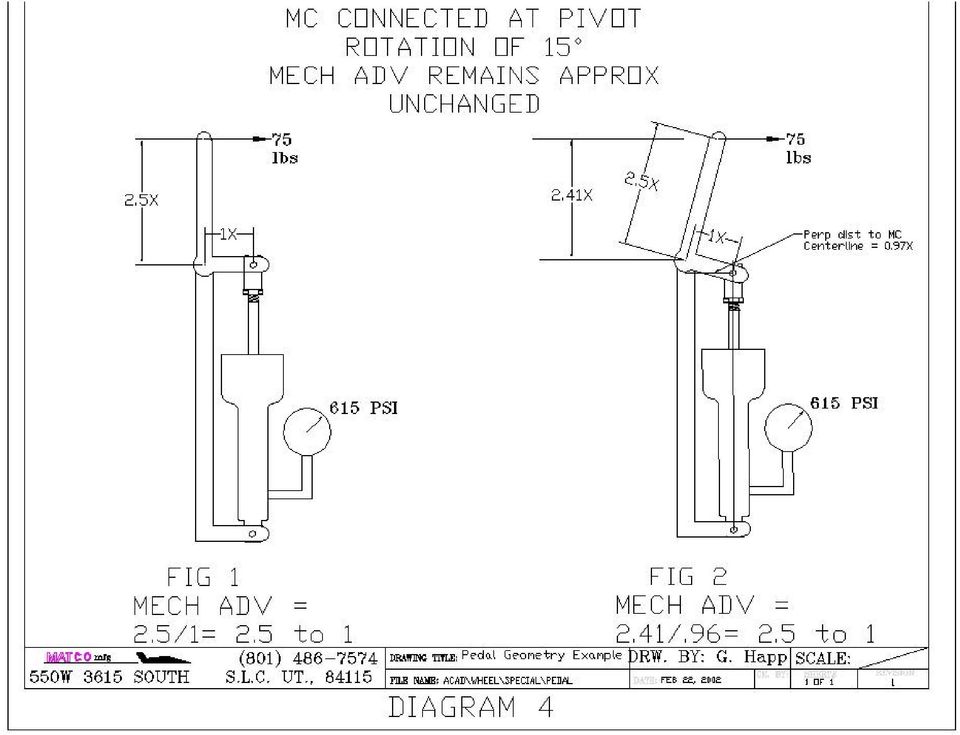
2 Get the Pressure Right! Assuming the calipers are properly mounted so that the pads make contact on both sides of the disc (both new and worn) and are maintained so that the caliper float freely, the most common reason for under performance of the brakes is low pressure. MATCO mfg brakes need 450 psi to achieve their rated torque. Additional calipers can be added to get higher torque at a lower pressure but it is often more weight efficient to modify the hydraulic system pedal geometry to generate high pressures. Systems using hand or foot operated master cylinders require a minimum of 2.5 to 1 mechanical advantage when using master cylinder, MC, like the MC-4 or MC-5 which have.625 inch diameter pistons. (Systems using MC-4 or MC-5 with intensifiers have.5 inch pistons and require a 1.6 to 1 mechanical advantage). Mechanical Advantage, MA, is the ratio of the force applied to the master cylinder shaft divided by the force applied by the hand or foot. Diagram 1 shows two examples of pedal geometry. The first has a MA of 1 to 1 since the distance from the applied load to the pivot point is the same as the distance to the MC and is undesirable. The second shows a more favorable configuration that will easily provide the required pressure to the brakes with moderate toe force. It is often necessary to keep the foot pedal shorter than that shown in Diagram 1. An alternative geometry is shown in Diagram 2. This design would utilize a fork arrangement on the MC connection to allow clearance of the MC body and then a short linkage to the MC connect point. A design common to many aircraft uses linkage as shown in Diagram 3. This design also allows for a shorter brake pedal but has a major disadvantage. This linkage can be configured to have proper MA in the start position (with the master cylinder fully extended). The MA varies with rotation however. As shown in Fig 2 of Diagram 3, a 15 degree rotation of the linkage reduces the MA at the start position from 1.5 to 1 down to only 1.12 to 1. In actual operation, this has the effect of causing a nearly constant brake torque even though increasing force is applied. For example, if the geometry is set for initial a MA of 2.5 to 1 in the start position and the pilot applies pedal force, the MC will begin to stroke as pressure builds. As the rotation occurs, the MA decreases. If there is any air in the brake lines or if there are long brake line runs, hydraulic system expansion will occur as pressure increase requiring more MC stroke. If the pilot applies more pedal force, more MC stroke occurs, and the MA decreases further. Even though the pilot has now increased his pedal force, the force applied to the MC will be only marginally increased because more rotation will result and cause a further decrease in MA. A geometry like that in Diagram 2 will provide the same reduced pedal height and is not prone to the effect of rotation since the MC is essentially connected to the brake pedal pivot. Diagram 4 illustrates the benefit of pivot connect geometry during rotation. The MA remains virtually unchanged for expected rotation angles and results in a linear pressure increase with applied pedal force. Heel Brakes A common means of providing pilots with differential braking ability without resorting to the more complicated geometry of toe brakes is to use heel brakes. The same design requirement exists for the MA of a system using heel brakes as for toe brakes. It is not uncommon to see MC's configured to allow the pilot to apply heel force directly to the MC by means of a pad or button connected on the end of the shaft. This configuration is shown in Fig 1 of Diagram 5. The MA of this system is 1 to 1 and produces very low pressure for reasonable heel force. Perhaps a larger concern however is the potential for causing damage to the MC. The MC is designed to accept loads applied along the length of the shaft. Loads applied off axis or perpendicular to the shaft cause bending moments in the MC shaft that it was not designed for. Damage to the MC end gland, or bending of the MC shaft may result if the off axis loads are high enough. A more desirable configuration for heel brakes is shown in Fig 2 of

3 Diagram 5. This system uses a short linkage connected to the MC that provides the 2.5 to 1 MA while insuring that loads will be applied along the length on the MC and prevent any damage during actuation. Conclusions Like any system on an aircraft, the hydraulic system has many engineering options for providing the necessary requirements. Systems common on light aircraft must be engineered to provide adequate pressure to the brakes to achieve the rated torque. MATCO mfg brakes require 450 psi to achieve the rated torque. The pedal geometry, whether hand, toe, or heel operated, requires a mechanical advantage of at least 2.5 to 1. This allows the pilot to easily generate the required 450 psi with moderate applied force. Pivot connected geometry provides the best means of accomplishing this requirement without the problem of rotational effect that reduce mechanical advantage.

4

5

6

7
8

BRAKE SYSTEM DESIGN AND THEORY
 RAKE SYSTEM DESIGN AND THEORY Aircraft brake systems perform multiple functions. They must be able to hold the aircraft back at full static engine run-up, provide adequate control during ground taxi operations,
Selecting and Sizing Ball Screw Drives
 Selecting and Sizing Ball Screw Drives Jeff G. Johnson, Product Engineer Thomson Industries, Inc. Wood Dale, IL 540-633-3549 www.thomsonlinear.com [email protected] Fig 1: Ball screw drive is a
(A5) Brakes Sample Questions and Answers
 Brakes Sample Questions and Answers") (A5) Brakes Sample Questions and Answers Answers to these questions are found beginning on page 4 of this document 1. Two technicians are discussing a problem where the brake pedal travels too far before
(A5) Brakes Sample Questions and Answers Answers to these questions are found beginning on page 4 of this document 1. Two technicians are discussing a problem where the brake pedal travels too far before
BRAKE SYSTEMS 101. Energy Conversion Management. Presented by Paul S. Gritt
 Energy Conversion Management Presented by Paul S. Gritt Topics To Be Presented The Basic Concepts Hydraulic layouts Component functions Brake Balance Stopping Distance and Fade Formula SAE vs. Mini Baja
Mechanical Systems. Grade 8 Unit 4 Test. 1. A wheelbarrow is an example of what simple machine? Class 1 lever. Class 2 lever.
 Mechanical Systems Grade 8 Unit 4 Test Student Class 1. A wheelbarrow is an example of what simple machine? D Wheel and Axle 2. A hockey stick is an example of what simple machine? D Inclined plane 3.
Mechanical & Hydraulic Clutch Linkage Set-Up Tips
 Mechanical & Hydraulic Clutch Linkage Set-Up Tips Setting the Stage Before getting to the actual clutch linkage system itself, it is assumed that you are using all of the correct clutch components that
How Do I Replacing My Rear Brake Pads and Rotors?
 How Do I Replacing My Rear Brake Pads and Rotors? WARNING! Always have the vehicle under inspection on level ground, in park with the emergency brake on. Always wear protective eyewear, gloves and necessary
COEFFICIENT OF KINETIC FRICTION
 COEFFICIENT OF KINETIC FRICTION LAB MECH 5.COMP From Physics with Computers, Vernier Software & Technology, 2000. INTRODUCTION If you try to slide a heavy box resting on the floor, you may find it difficult
Class 5 to 7 Truck and Bus Hydraulic Brake System
 Class 5 to 7 Truck and Bus Hydraulic Brake System Diagnostic Guide 1st Edition * 5+0 Important Service tes The information in this publication was current at the time of printing. The information presented
STATIC AND KINETIC FRICTION
 STATIC AND KINETIC FRICTION LAB MECH 3.COMP From Physics with Computers, Vernier Software & Technology, 2000. INTRODUCTION If you try to slide a heavy box resting on the floor, you may find it difficult
Choosing Between Electromechanical and Fluid Power Linear Actuators in Industrial Systems Design
 Choosing Between Electromechanical and Fluid Power Linear Actuators in Industrial Systems Design James Marek, Business Unit Director, Thomson Systems Thomson Industries, Inc. 540-633-3549 www.thomsonlinear.com
Example. Fluid Power. Circuits
 Example Fluid Power Circuits To Enhance Symbol Reading Skills To Work On Circuit Reading Skills With Answers HI LO Pump Circuit 18 A1 B1 17 16 15 13 Set 14 2,000 PSI PG2 Set 500 PSI 12 11 7 8 10 PG1 9
Slide 10.1. Basic system Models
 Slide 10.1 Basic system Models Objectives: Devise Models from basic building blocks of mechanical, electrical, fluid and thermal systems Recognize analogies between mechanical, electrical, fluid and thermal
Rules of Actuator and Guide Alignment in Linear Motion Systems
 Rules of Actuator and Guide Alignment in Linear Motion Systems By Gary Rosengren, Director of Engineering Tolomatic, Inc. About the Author Gary Rosengren is Director of Engineering at Tolomatic and has
APPENDIX A CONTROL VALVE TESTING PROCEDURES AND EQUATIONS FOR LIQUID FLOWS
 APPENDIX A CONTROL VALVE TESTING PROCEDURES AND EQUATIONS FOR LIQUID FLOWS Section A.1. Flow Coefficients Definition The flow coefficient or pressure loss coefficient is used to relate the pressure loss
Autonomous Mobile Robot-I
 Autonomous Mobile Robot-I Sabastian, S.E and Ang, M. H. Jr. Department of Mechanical Engineering National University of Singapore 21 Lower Kent Ridge Road, Singapore 119077 ABSTRACT This report illustrates
Fig 1 Power Transmission system of Tractor
 POWER TRANSMISSION SYSTEM Transmission is a speed reducing mechanism, equipped with several gears (Fig. 1). It may be called a sequence of gears and shafts, through which the engine power is transmitted
Shaft- Mounted Speed Reducers
 Torque Arm Design Considerations for Todd R. Bobak has worked in the gear industry for 15 years. He has held positions in technical service, design and development, and quality assurance. He is a product
Experiment: Static and Kinetic Friction
 PHY 201: General Physics I Lab page 1 of 6 OBJECTIVES Experiment: Static and Kinetic Friction Use a Force Sensor to measure the force of static friction. Determine the relationship between force of static
Pump ED 101. Positive Displacement Pumps. Part I Reciprocating Pumps
 Pump ED 101 Positive Displacement Pumps Part I Reciprocating Pumps Joe Evans, Ph.D http://www.pumped101.com There are many pump designs that fall into the positive displacement category but, for the most
Application Information
 Moog Components Group manufactures a comprehensive line of brush-type and brushless motors, as well as brushless controllers. The purpose of this document is to provide a guide for the selection and application
FEA Analysis of a Caliper Abutment Bracket ME 404
 FEA Analysis of a Caliper Abutment Bracket ME 404 Jesse Doty March 17, 2008 Abstract As braking forces are applied at the wheel of an automobile, those forces must be transmitted to the suspension of the
Why Lead Screws are the Best Fit for Many Linear Motion Applications - and How to Rightly Apply Them
 Why Lead Screws are the Best Fit for Many Linear Motion Applications - and How to Rightly Apply Them Robert Lipsett, Engineering Manager, Thomson BSA Thomson Industries, Inc. San Jose, CA 800.882.8857
Belt Drives and Chain Drives. Power Train. Power Train
 Belt Drives and Chain Drives Material comes for Mott, 2002 and Kurtz, 1999 Power Train A power train transmits power from an engine or motor to the load. Some of the most common power trains include: Flexible
Electro-Mechanical Landing Gear System. Landing Gear and Brakes
 Electro-Mechanical Landing Gear System N O 2 D U A L F E D B U S LANDING RELAY 5A DOWN EMERGENCY EXTENSION DOWN LIMIT GROUND AIRBORNE DOWN LIMIT Landing Gear and Brakes DOWNLOCK HOOK ENGAGED GROUND AIRBORNE
Using Design Accelerators in Autodesk Inventor
 Using Design Accelerators in Autodesk Inventor Ravi Akella Autodesk, Inc. Ales Ricar Autodesk, Inc. MA 201-3P Getting things in gear are easy with the Design Accelerators in Autodesk Inventor. Find out
1x90 TONS TENSIONERS TECHNICAL PROPOSAL. 1 X 90 Tons 30 m/min Tensioners TECHNICAL PROPOSAL JOB 08/059. 0 19/02/2008 Basic proposal PP GM SB
 Pagina N.: 1 of 19 1 X 90 Tons 30 m/min Tensioners JOB 08/059 0 19/02/2008 Basic proposal PP GM SB Rev N Date Issue Description Prepared by Checked by Approved by Pagina N.: 2 of 19 TABLE OF CONTENTS:
Manufacturing Equipment Modeling
 QUESTION 1 For a linear axis actuated by an electric motor complete the following: a. Derive a differential equation for the linear axis velocity assuming viscous friction acts on the DC motor shaft, leadscrew,
Practice Exam Three Solutions
 MASSACHUSETTS INSTITUTE OF TECHNOLOGY Department of Physics Physics 8.01T Fall Term 2004 Practice Exam Three Solutions Problem 1a) (5 points) Collisions and Center of Mass Reference Frame In the lab frame,
Module 2 - GEARS Lecture 7 - SPUR GEAR DESIGN
 Module 2 - GEARS Lecture 7 - SPUR GEAR DESIGN Contents 7.1 Spur gear tooth force analysis 7.2 Spur gear - tooth stresses 7.3 Tooth bending stress Lewis equation 7.4 Tooth bending stress AGMA procedure
RT100 ROUGH TERRAIN CRANE DATASHEET - IMPERIAL. Features:
 ROUGH TERRAIN CRANE DATASHEET - IMPERIAL Features: Rated capacity: 100 ton @ 10 ft working radius Maximum boom length: 174 ft Maximum tip height: 183 ft Maximum hook height: 174.5 ft CONTENTS Key............................................................................................
Chapter 18: Brakes and Clutches
 Chapter 18: Brakes and Clutches Nothing has such power to broaden the mind as the ability to investigate systematically and truly all that comes under thy observation in life. Marcus Aurelius, Roman Emperor
Pentalift Equipment Corporation Lift table and positioning equipment glossary of terms
 Pentalift Equipment Corporation Lift table and positioning equipment glossary of terms Access Plate removable or hinged plate which permits access to components that are covered by some portion of the
Dampers. Inlet guide vane. Damper. Louvre damper. Handbook Radial Fans / Chapter 3 - Dampers REITZ List 2010 DO 1. Dampers
 Inlet guide vane Damper ouvre damper Handbook Radial Fans / Chapter 3 - REITZ ist 2010 DO 1 Technical description rticle number and order code article number = component size DR D1 0 3-000 031-00 variant
Index 11.1. Page. Pumping Systems...11.2-11.4 Intensifiers...11.5 Gas Boosters...11.6-11.7 High Pressure Generators...11.8-11.9
 Pumping Systems, Intensifiers, Gas Boosters and High Pressure Generators High Pressure Equipment Company produces a number of components and systems for general industrial, elevated pressure applications.
DYNA RIDER FOOTBOARD KIT
 -J0 REV. 0-0-0 DYNA RIDER FOOTBOARD KIT GENERAL Kit Number 000 Models For model fitment information, see the P&A Retail Catalog or the Parts and Accessories section of www.harley-davidson.com (English
DiscPlus DX195 and DX225 Air Disc Brakes
 Revised 11-04 Technical Bulletin Revised 1 Technical 11-04 Bulletin DiscPlus DX195 and DX225 Air Disc Brakes Inspection, Installation and Diagnostics Air Disc Brake Inspection Intervals and Procedures
Experiment 3 Pipe Friction
 EML 316L Experiment 3 Pipe Friction Laboratory Manual Mechanical and Materials Engineering Department College of Engineering FLORIDA INTERNATIONAL UNIVERSITY Nomenclature Symbol Description Unit A cross-sectional
Midterm Solutions. mvr = ω f (I wheel + I bullet ) = ω f 2 MR2 + mr 2 ) ω f = v R. 1 + M 2m
 = ω f 2 MR2 + mr 2 ) ω f = v R. 1 + M 2m") Midterm Solutions I) A bullet of mass m moving at horizontal velocity v strikes and sticks to the rim of a wheel a solid disc) of mass M, radius R, anchored at its center but free to rotate i) Which of
Midterm Solutions I) A bullet of mass m moving at horizontal velocity v strikes and sticks to the rim of a wheel a solid disc) of mass M, radius R, anchored at its center but free to rotate i) Which of
E. K. A. ADVANCED PHYSICS LABORATORY PHYSICS 3081, 4051 NUCLEAR MAGNETIC RESONANCE
 E. K. A. ADVANCED PHYSICS LABORATORY PHYSICS 3081, 4051 NUCLEAR MAGNETIC RESONANCE References for Nuclear Magnetic Resonance 1. Slichter, Principles of Magnetic Resonance, Harper and Row, 1963. chapter
MCE380: Measurements and Instrumentation Lab. Chapter 9: Force, Torque and Strain Measurements
 MCE380: Measurements and Instrumentation Lab Chapter 9: Force, Torque and Strain Measurements Topics: Elastic Elements for Force Measurement Dynamometers and Brakes Resistance Strain Gages Holman, Ch.
The dynamic equation for the angular motion of the wheel is R w F t R w F w ]/ J w
![The dynamic equation for the angular motion of the wheel is R w F t R w F w ]/ J w](/thumbs/25/5134815.jpg "The dynamic equation for the angular motion of the wheel is R w F t R w F w ]/ J w") Chapter 4 Vehicle Dynamics 4.. Introduction In order to design a controller, a good representative model of the system is needed. A vehicle mathematical model, which is appropriate for both acceleration
Chapter 4 Vehicle Dynamics 4.. Introduction In order to design a controller, a good representative model of the system is needed. A vehicle mathematical model, which is appropriate for both acceleration
Shear Force and Moment Diagrams
 C h a p t e r 9 Shear Force and Moment Diagrams In this chapter, you will learn the following to World Class standards: Making a Shear Force Diagram Simple Shear Force Diagram Practice Problems More Complex
Lab 7: Rotational Motion
 Lab 7: Rotational Motion Equipment: DataStudio, rotary motion sensor mounted on 80 cm rod and heavy duty bench clamp (PASCO ME-9472), string with loop at one end and small white bead at the other end (125
Unit 24: Applications of Pneumatics and Hydraulics
 Unit 24: Applications of Pneumatics and Hydraulics Unit code: J/601/1496 QCF level: 4 Credit value: 15 OUTCOME 2 TUTORIAL 2 HYDRAULIC AND PNEUMATIC CYLINDERS The material needed for outcome 2 is very extensive
30 minutes in class, 2 hours to make the first time
 Asking questions and defining problems Developing and using models Planning and carrying out investigations 30 minutes in class, 2 hours to make the first time 3 12 x 24 x ¾ inch plywood boards 1 x 12
Solution Derivations for Capa #11
 Solution Derivations for Capa #11 1) A horizontal circular platform (M = 128.1 kg, r = 3.11 m) rotates about a frictionless vertical axle. A student (m = 68.3 kg) walks slowly from the rim of the platform
Electric Motors and Drives
 EML 2322L MAE Design and Manufacturing Laboratory Electric Motors and Drives To calculate the peak power and torque produced by an electric motor, you will need to know the following: Motor supply voltage,
Hydraulic Disc Brake, Installation, Maintenance, and Service Manual
 Hydraulic Disc Brake, Installation, Maintenance, and Service Manual HFX-Mag HFX-9 45-14550DWeb 02/06 copyright 2006 Hayes Bicycle Group, LLC Introduction to this Manual This manual is intended to provide
Introduction of Duplex Pump HPD71+71 and Short-Stroke Pump HPV112+112
 Shin-ichi Kamimura Komatsu has come up with a high-pressure, large-capacity, duplex swash plate pump, HPD71+71, as the main pump for PC160-7 and a short-length, tandem swash plate pump (short-stroke pump),
Aeroplane Wheels and Wheel-Brake Assemblies - Minimum Performance Standards
 ISBN 1 904862 78 0 Specification No. 17 United Kingdom Civil Aviation Authority Issue: 1 Date: 18 September 1986 Aeroplane Wheels and Wheel-Brake Assemblies - Minimum Performance Standards NOTE: THIS SPECIFICATION
2 Axis Solar Tracker / 12 Kw
 2 Axis Solar Tracker / 12 Kw 4 Rows 14 metres 4 rows x 14 metres Quantity / Panel Type: 68 units Photovoltaic panel 1.600 x 790 mm Panel power / Total power: 165 W 11,2 Kw Total Surface: 94 m² Diameter
ANTI LOCK BRAKING SYSTEM MODELLING AND DEVELOPMENT
 ANTI LOCK BRAKING SYSTEM MODELLING AND DEVELOPMENT Aldi Manikanth ME10B004 A Manoj Kumar ME10B006 C Vijay Chauhan ME10B010 Nachiket Dongre ME10B013 Lithas ME10B020 Rajesh Kumar Meena ME10B030 Varada Karthik
UNIT II Robots Drive Systems and End Effectors Part-A Questions
 UNIT II Robots Drive Systems and End Effectors Part-A Questions 1. Define End effector. End effector is a device that is attached to the end of the wrist arm to perform specific task. 2. Give some examples
Physics 1A Lecture 10C
 Physics 1A Lecture 10C "If you neglect to recharge a battery, it dies. And if you run full speed ahead without stopping for water, you lose momentum to finish the race. --Oprah Winfrey Static Equilibrium
AWWA Butterfly Valve Operation and Maintenance Manual Series 511A & 510A 20 and Smaller
 January 2013 AWWA Butterfly Valve Operation and Maintenance Manual Series 511A & 510A 20 and Smaller Milliken Valve Company 190 Brodhead Avenue, Suite 100 Bethlehem, PA 18017 Phone: (610) 861-8803 Fax:
Michael Montgomery Marketing Product Manager Rosemount Inc. Russ Evans Manager of Engineering and Design Rosemount Inc.
 ASGMT / Averaging Pitot Tube Flow Measurement Michael Montgomery Marketing Product Manager Rosemount Inc. Russ Evans Manager of Engineering and Design Rosemount Inc. Averaging Pitot Tube Meters Introduction
Three Channel Optical Incremental Encoder Modules Technical Data
 Three Channel Optical Incremental Encoder Modules Technical Data HEDS-9040 HEDS-9140 Features Two Channel Quadrature Output with Index Pulse Resolution Up to 2000 CPR Counts Per Revolution Low Cost Easy
High Pressure Equipment Pressure Vessels and Reactors Index
 Pressure Vessels and Reacrs High Pressure Equipment Company designs and manufactures a broad range of pressure vessels and reacrs for both bench-scale and pilot plant applications. We have over 0 standard
Volkswagen B3 Passat Manual Transmission 02A 34 Manual Transmission - Controls, Assembly (Page GR-34) 02A 5-speed. Gearshift cable/lever installing
 02A 5-speed. Gearshift cable/lever installing") 34 Manual Transmission - Controls, Assembly (Page GR-34) 02A 5-speed Gearshift cable/lever installing Gearshift housing repairing Gearshift lever repairing lever/relay lever, installing Gearshift mechanism
34 Manual Transmission - Controls, Assembly (Page GR-34) 02A 5-speed Gearshift cable/lever installing Gearshift housing repairing Gearshift lever repairing lever/relay lever, installing Gearshift mechanism
HW Set VI page 1 of 9 PHYSICS 1401 (1) homework solutions
 homework solutions") HW Set VI page 1 of 9 10-30 A 10 g bullet moving directly upward at 1000 m/s strikes and passes through the center of mass of a 5.0 kg block initially at rest (Fig. 10-33 ). The bullet emerges from the
HW Set VI page 1 of 9 10-30 A 10 g bullet moving directly upward at 1000 m/s strikes and passes through the center of mass of a 5.0 kg block initially at rest (Fig. 10-33 ). The bullet emerges from the
Belt Tensioning Methods for Small Package Conveyors What s the best solution?
 Belt Tensioning Methods for Small Package Conveyors What s the best solution? Industrial White Paper By: Michael A. Hosch, P.E. Dorner Mfg. Corp. 975 Cottonwood Avenue Hartland, WI 53029 USA Phone: 800
PVM Piston Pumps Service Manual
 PVM Piston Pumps Service Manual PVM018/020 PVM045/050 PVM057/063 PVM074/081 PVM098/106 PVM131/141 Table of Contents Service Parts Pump Description... 3 Basic pump Pump Operation Controls Types Part Identification...
7600 SAND STREET, FORT WORTH, TX 76118. www.kodiaktrailer.com -2-
 7600 SAND STREET, FORT WORTH, TX 76118 www.kodiaktrailer.com -2- CONTENTS SECTION I. INTRODUCTION II. GENERAL INFORMATION III. SAFETY INFORMATION IV. INSTALLATION INFORMATION V. SOLENOID REVERSING VALVES
8.2 Elastic Strain Energy
 Section 8. 8. Elastic Strain Energy The strain energy stored in an elastic material upon deformation is calculated below for a number of different geometries and loading conditions. These expressions for
Hydraulic Landing Gear System
 Hydraulic Landing Gear System CENTER BUS MAIN POWER RELAY 60A 5A SERVICE VALVE 5 LANDING GEAR TIME DELAY PCB TIME DELAY 14 AUX. RETURN AUX. PRESS. UP SELECTOR VALVE POWER PACK ASSEMBLY REGULATED BLEED
Kart Owner s Manual. www.tecnokart.com
 Kart Owner s Manual www.tecnokart.com Introduction Thank you for choosing Tecno kart. You have in your possession one of the finest kart products in the world. We are proud to be your brand of choice.
Chapter 11 SERVO VALVES. Fluid Power Circuits and Controls, John S.Cundiff, 2001
 Chapter 11 SERVO VALVES Fluid Power Circuits and Controls, John S.Cundiff, 2001 Servo valves were developed to facilitate the adjustment of fluid flow based on the changes in the load motion. 1 Typical
WINDER SYSTEMS GE Industrial Control Systems
 WINDER SYSTEMS Systems Concepts Terminology GE Industrial Control Systems APPLICATION TECHNIQUES With a smooth metal surface material, a paper liner is sometimes wound with a coil. The paper is lightweight
The Pressure Velocity (PV) Relationship for Lead Screws
 Relationship for Lead Screws") The Pressure Velocity (PV) Relationship for Lead Screws Robert Lipsett, Engineering Manager Thomson Industries, Inc. Wood Dale, IL 540-633-3549 www.thomsonlinear.com The Pressure Velocity (PV) factor is
The Pressure Velocity (PV) Relationship for Lead Screws Robert Lipsett, Engineering Manager Thomson Industries, Inc. Wood Dale, IL 540-633-3549 www.thomsonlinear.com The Pressure Velocity (PV) factor is
A descriptive definition of valve actuators
 A descriptive definition of valve actuators Abstract A valve actuator is any device that utilizes a source of power to operate a valve. This source of power can be a human being working a manual gearbox
Hidetsugu KURODA 1, Fumiaki ARIMA 2, Kensuke BABA 3 And Yutaka INOUE 4 SUMMARY
 PRINCIPLES AND CHARACTERISTICS OF VISCOUS DAMPING DEVICES (GYRO-DAMPER), THE DAMPING FORCES WHICH ARE HIGHLY AMPLIFIED BY CONVERTING THE AXIAL MOVEMENT TO ROTARY ONE 0588 Hidetsugu KURODA 1, Fumiaki ARIMA,
Chapter 2 Lead Screws
 Chapter 2 Lead Screws 2.1 Screw Threads The screw is the last machine to joint the ranks of the six fundamental simple machines. It has a history that stretches back to the ancient times. A very interesting
Deflections. Question: What are Structural Deflections?
 Question: What are Structural Deflections? Answer: The deformations or movements of a structure and its components, such as beams and trusses, from their original positions. It is as important for the
Design of a Universal Robot End-effector for Straight-line Pick-up Motion
 Session Design of a Universal Robot End-effector for Straight-line Pick-up Motion Gene Y. Liao Gregory J. Koshurba Wayne State University Abstract This paper describes a capstone design project in developing
RT 780. RT 780 80 USt Lifting Capacity Rough Terrain Cranes Datasheet Imperial. Features
 USt Lifting Capacity Rough Terrain Cranes Datasheet Imperial Features Rated capacity: US t @ ft working radius Maximum boom length: 126 ft Maximum tip height: 1 ft CONTENTS Page: Key...3 Dimensions Crane
PHYS 211 FINAL FALL 2004 Form A
 1. Two boys with masses of 40 kg and 60 kg are holding onto either end of a 10 m long massless pole which is initially at rest and floating in still water. They pull themselves along the pole toward each
Rear wheel brakes, servicing. Стр. 1 из 45. Note:
 Volkswagen Touareg - Rear wheel brakes, servicing Стр. 1 из 45 46-2 Rear wheel brakes, servicing Rear brakes, FN 44 brake caliper, servicing Note: After replacing brake pads, depress brake pedal firmly
SUPPLEMENTAL TECHNICAL SPECIFICATIONS BI-DIRECTIONAL STATIC LOAD TESTING OF DRILLED SHAFTS
 July 14, 2015 1.0 GENERAL BI-DIRECTIONAL STATIC LOAD TESTING OF DRILLED SHAFTS This work shall consist of furnishing all materials, equipment, labor, and incidentals necessary for conducting bi-directional
Design of Impact Load Testing Machine for COT
 Design of Impact Load Testing Machine for COT Sandesh G.Ughade 1, Dr. A.V.Vanalkar 2, Prof P.G.Mehar 2 1 Research Scholar (P.G), Dept of Mechanical Engg, KDK College of Engg, Nagpur, R.T.M, Nagpur university,
STEERING HANDLEBAR/FRONT WHEEL/ FRONT SHOCK ABSORBER
 14 14 STEERING HANDLEBAR/FRONT WHEEL/ SCHEMATIC DRAWING ------------------------------------------------- 14-1 SERVICE INFORMATION------------------------------------------------ 14-2 TROUBLESHOOTING-----------------------------------------------------
Open Channel Diffusers
 Open Channel Diffusers Application Information: Open channel diffusers are used to increase mixing and absorbance efficiency of a chemical solution into the process water. Specifically designed penetrations
SOLID MECHANICS DYNAMICS TUTORIAL MOMENT OF INERTIA. This work covers elements of the following syllabi.
 SOLID MECHANICS DYNAMICS TUTOIAL MOMENT OF INETIA This work covers elements of the following syllabi. Parts of the Engineering Council Graduate Diploma Exam D5 Dynamics of Mechanical Systems Parts of the
INTERNATIONAL HOCKEY FEDERATION PERFORMANCE REQUIREMENTS AND TEST PROCEDURES FOR HOCKEY BALLS. Published: April 1999
 INTERNATIONAL HOCKEY FEDERATION PERFORMANCE REQUIREMENTS AND TEST PROCEDURES FOR HOCKEY BALLS Published: April 1999 CONTENTS 1 Introduction 2 Test Procedures General 3 Standards and Specific Test Procedures
US ARMY LIGHT WHEEL VEHICLE MECHANIC MOS 63B SKILL LEVEL 3 COURSE WHEELED VEHICLE BRAKING SYSTEMS SUBCOURSE NO. OD1008
 US ARMY LIGHT WHEEL VEHICLE MECHANIC MOS 63B SKILL LEVEL 3 COURSE WHEELED VEHICLE BRAKING SYSTEMS SUBCOURSE NO. OD1008 US Army Ordnance Center and School Five Credit Hours GENERAL The Wheeled Vehicle Braking
CONTROL LOADING SOLUTIONS
 CONTROL LOADING SOLUTIONS A FULL RANGE OF CONTROL LOADING SOLUTIONS FOR FIXED AND ROTARY WING Rev 2, 0709 WHAT MOVES YOUR WORLD TAKE YOUR CONTROL LOADING SYSTEMS TO NEW HEIGHTS With a few decades of experience
Material taken from Fluid Power Circuits and Controls, John S. Cundiff, 2001
 Pressure Control Chapter 3 Material taken from Fluid Power Circuits and Controls, John S. Cundiff, 2001 Introduction Pressure control is a key element in the design of any circuit. Used correctly, it can
Procedures for daily inspection and testing of mechanical power presses and press brakes
 Procedures for daily inspection and testing of mechanical power presses and press brakes INTRODUCTION This leaflet gives guidance on the minimum safety checks that should be carried out on mechanical power
Gear Trains. Introduction:
 Gear Trains Introduction: Sometimes, two or more gears are made to mesh with each other to transmit power from one shaft to another. Such a combination is called gear train or train of toothed wheels.
McCAULEY CONSTANT SPEED PROPELLER GOVERNING SYSTEM
 Professor Von Kliptip Answers Your Questions About The McCAULEY CONSTANT SPEED PROPELLER GOVERNING SYSTEM FOR NON-COUNTERWEIGHTED PRESSURE TO INCREASE PITCH PROPELLERS ON TYPICAL SINGLE ENGINE AIRCRAFT
Nozzle Loads, Piping Stresses, and the Effect of Piping on Equipment
 Nozzle Loads, Piping Stresses, and the Effect of Piping on Equipment By Patty Brown & Mark van Ginhoven November 13, 2009 1 CA 2009 Fluor Corporation. All Rights Reserved. Topics Covered Introduction Nozzle
Automatic Transmission Basics
 Automatic Transmission Basics Lesson Objectives 1. Describe the function of the torque converter. 2. Identify the three major components of the torque converter that contribute to the multiplication of
NATIONAL CERTIFICATE (VOCATIONAL)
") NATIONAL CERTIFICATE (VOCATIONAL) SUBJECT GUIDELINES AUTOMOTIVE REPAIR AND MAINTENANCE NQF LEVEL 3 Implementation: January 2014 INTRODUCTION A. What is Automotive Repair and Maintenance Level 3 about?
NATIONAL CERTIFICATE (VOCATIONAL) SUBJECT GUIDELINES AUTOMOTIVE REPAIR AND MAINTENANCE NQF LEVEL 3 Implementation: January 2014 INTRODUCTION A. What is Automotive Repair and Maintenance Level 3 about?
MASTER CYLINDER. Section 2. Master Cylinder. Tandem Master Cylinder. Master Cylinder
 MASTER CYLINDER Master Cylinder The master cylinder converts the motion of the brake pedal into hydraulic pressure. It consists of the reservoir tank, which contains the brake fluid; and the piston and
Bendix Air Disc Brakes
 Bendix Air Disc Brakes Optimum Performance. Optimum Engineering. A i r D r u m B r a k e s A i r D i s c B r a k e s A i r B r a k e C h a m b e r s S l a c k A d j u s t e r s H y d r a u l i c s A major
2007 Hummer H3. 2007 BRAKES Disc Brakes - H3. Fastener Tightening Specifications Specification Application
 2007 BRAKES Disc Brakes - H3 SPECIFICATIONS FASTENER TIGHTENING SPECIFICATIONS Fastener Tightening Specifications Specification Application Metric English Backing Plate Bolts 135 N.m 100 lb ft Brake Hose
Rotary actuators Rotary wing drives Series RAK. Brochure
 Brochure 2 Rotary wing drives, angle of rotation: 30-270 Rotary wing drive, double-acting axis geometry: single 4 Rotary wing drives, angle of rotation: 90-270 Rotary wing drive, double-acting axis geometry:
ME 239: Rocket Propulsion. Over- and Under-expanded Nozzles and Nozzle Configurations. J. M. Meyers, PhD
 ME 239: Rocket Propulsion Over- and Under-expanded Nozzles and Nozzle Configurations J. M. Meyers, PhD 1 Over- and Underexpanded Nozzles Underexpanded Nozzle Discharges fluid at an exit pressure greater