ANTI LOCK BRAKING SYSTEM MODELLING AND DEVELOPMENT
|
|
|
- Holly Reynolds
- 9 years ago
- Views:
Transcription
1 ANTI LOCK BRAKING SYSTEM MODELLING AND DEVELOPMENT Aldi Manikanth ME10B004 A Manoj Kumar ME10B006 C Vijay Chauhan ME10B010 Nachiket Dongre ME10B013 Lithas ME10B020 Rajesh Kumar Meena ME10B030 Varada Karthik ME10B038

2 Introduction ABS prevents locking of wheels during braking During severe braking or on slippery surfaces, wheels approach lockup. At that time, ABS takes over ABS modulates the brake line pressure independent of the pedal force, to bring the wheel speed back to the slip level range that is necessary for optimal braking performance. Video Courtesy: Maplesoft Software Used: Maple Sim

3 Motivation Though Anti lock Braking System has already been implemented in sophisticated cars, still the technology is considered as a cutting edge. As far as automotive industry is concerned ABS technology is most recent development in enhancing passenger safety and accident avoidance. A 2004 Australian study by Monash University Accident Research Centre found that ABS Reduced the risk of multiple vehicle crashes by 18 percent, Reduced the risk of run-off-road crashes by 35 percent. That is why, we felt it is important as well as challenging to study

4 Car Model Brake System model How ABS works?? Mathematical model System model Results Discussion Conclusion References Project Outline

5 Maserati GranTurismo!! CAR MODEL

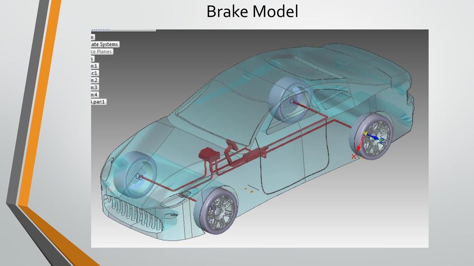
6 Brake Model
7 ABS consists of Wheel speed sensors Controller unit Hydraulic modulator Unit Braking device How ABS works

8 How ABS works - Subsystems Wheel Speed Sensors Electro-magnetic or Hall-effect pulse pickups with toothed wheels mounted directly on the rotating components of the drivetrain or wheel hubs. As the wheel turns the toothed wheel (pulse ring) generates an AC voltage at the wheel-speed sensor. The voltage frequency is directly proportional to the wheel's rotational speed. Electronic Controller Unit The electronic control unit receives, amplifies and filters the sensor signals for calculating the wheel rotational speed and acceleration. ABS is usually implemented here. ECU assists the vehicle operator to prevent wheel lockup by regulating the wheel slip. Hydraulic Unit The hydraulic pressure modulator is an electro-hydraulic device for reducing, holding, and restoring the pressure of the wheel brakes by manipulating the solenoid valves in the hydraulic brake system. Hydraulic unit actuates the brakes by increasing the hydraulic pressure or bypassing the pedal force to reduce the braking power. Depending on the design, this device may include a pump, motor assembly, accumulator and reservoir

9 How ABS works When a wheel lockup is detected or eminent, ECU commands HCU to release the brake pressure to allow the wheel velocity to increase and the wheel slip to decrease. Once the wheel velocity spins up, ECU re-applies the brake pressure to confine the wheel slip to a predetermined value or interval. HCU Controls hydraulic brake pressure to each disc brake caliper or wheel cylinder based on input from the system sensors, thereby controlling wheel speed.

10 Objectives of ABS 1. To reduce stopping distances The distance to stop is a function of the mass of the vehicle, the initial velocity, and the braking force. By maximizing the braking force the stopping distance will be minimized if all other factors remain constant. However, on all types of surfaces, to a greater or lesser extent, there exists a peak in fiction coefficient. It follows that by keeping all of the wheels of a vehicle near the peak, an antilock system can attain maximum fictional force and, therefore, minimum stopping distance.

11 Objectives of ABS 2. Stability Although decelerating and stopping vehicles constitutes a fundamental purpose of braking systems, maximum friction force may not be desirable in all cases For example not if the vehicle is on a so-called p-split surface (asphalt and ice, for example), such that significantly more braking force is obtainable on one side of the vehicle than on the other side. Applying maximum braking force on both sides will result in a yaw moment that will tend to pull the vehicle to the high friction side and contribute to vehicle instability, and forces the operator to make excessive steering corrections to counteract the yaw moment. If an antilock system can maintain the slip of both rear wheels at the level where the lower of the two friction coefficients peaks, then lateral force is reasonably high, though not maximized. This contributes to stability

12 Objectives of ABS 3.Steerability Good peak frictional force control is necessary in order to achieve satisfactory lateral forces and, therefore, satisfactory steerability. Steerability while braking is important not only for minor course corrections but also for the possibility of steering around an obstacle. Tire characteristics play an important role in the braking and steering response of a vehicle. For ABS-equipped vehicles the tire performance is of critical significance. All braking and steering forces must be generated within the small tire contact patch between the vehicle and the road. Tire traction forces as well as side forces can only be produced when a difference exists between the speed of the tire circumference and the speed of the vehicle relative to the road surface.

13 Mathematical Model Quarter vehicle/single wheel model Brake torque and friction force Two DOF model Vx and ω Equations of Motion ma x = μ F N Jω = μrf N T b Slip Ratio = λ = V x ωr V x Slip rate = λ = V x 1 λ Rω V x

14 Mathematical Model State Space representation State Variables are x 1 = S x, x 2 = V x, x 3 = λ State Space Equations are x 1 = x 2 x 2 = μf N m x 3 = μf N 1 x 3 x 2 m + R2 J w + R J w x 2 T b

15 Mathematical Model If the wheel velocity is zero (ω=0), the wheel slip will equal to 1 (λ=1). It means that the wheel is locked. However, if v = ωr, the wheel slip will equal to zero (λ=0). It is usually called free rolling. The longitudinal coefficient (µ) of friction between tyre and road is a nonlinear function of the wheel slip (λ).

16 Mathematical Model When the vehicle is under perfectly braking maneuver, for a small applied braking torque, the wheel velocity starts to decrease and the wheel slip starts to increase from zero. Now if slip is less than 0.2, then with the rise of slip, frictional coefficient also increases which is resulting in the rise of frictional force and consequently wheel velocity increases, resulting in the decrease of slip. But for a hard braking torque, the wheel slip may go straightly to a large number, which causes the µ to pass its peak point and reach somewhere in the decreasing part of the µ-slip curve, where with the rise of slip, frictional force decreases and consequently wheel velocity decreases constantly. If the brake torque is not reduced quickly at this point, the reduction of the road friction force will lead to a rapid increase of the wheel slip and eventually to a wheel lockup. Ideally ABS tries to maintain wheel slip at the peak of µ-slip curve, so that maximum friction force and consequently minimum vehicle stopping distance can be achieved. However maintaining wheel slip at the peak of µ-slip curve is always very difficult, as peak of the µ-slip curve does change with the varying surface and varying vehicle velocity.

17 Mathematical Model The friction coefficient can vary in a very wide range, depending on factors like: Road surface conditions (dry or wet) Tire side-slip angle Tire brand (summer tire, winter tire) Vehicle speed The slip ratio between the tire and the road. Friction model : μ( λ, V x ) = [c 1 (1 e c 2λ ) c 3 λ]e c 4V x

18 Control System A feedback control system is a closed loop control system in which a sensor monitors the output (slip ratio) and feeds data to the controller which adjusts the control (brake pressure modulator) as necessary to maintain the desired system output (match the wheel slip ratio to the reference value of slip ratio).

19 Control System Feedback controller used are : P Controller PD Controller PI Controller PID controller u = K p e + K I e dt + K D de dt

20 System model using Simulink

21 ABS model
22 Slip Calculator Friction Calculator (u(1)*(1-u(4))-(r*u(3)))/(u(2) + (u(2)==0)*eps) [c 1 (1 e c 2u 1 ) c 3 u(1)]e c 4u(2)
23 Parameters R =0.352 m=493 c1= c2=23.99 c3=0.52 J=1.13 c4=0.03 g=9.81 FN =m*g Tb=1500 V0=(5* )/18 W0=V0/R
24 Open loop model Angular velocity vs. time Results
25 Open loop model Stopping distance vs. time Results
26 Open loop model Slip vs. time Results
27 P controller Slip Vs. Time Results
28 PD controller Slip Vs. Time Results
29 PI controller Slip Vs. Time Results
30 PID controller Slip Vs. Time Results
31 P controller Stopping Distance Vs. Time Results
32 PD controller Stopping Distance Vs. Time Results

33 PI controller Stopping Distance Vs. Time Results
34 PID controller Stopping Distance Vs. Time Results
35 Comparision Controller Stopping Time Stopping Distance Open loop P PD PI PID
36 Discussion It is obvious that ABS improves the braking performance The stopping distance after using ABS system has considerably reduced. The error in slip and desired slip is used to manipulate brake pressure in brake cylinder. Only a linear model was considered and does not include actual road conditions. The system here is modelled only for straight line braking. In case of cornering, the side slip ratio would be controlled so that wheels don t lock and thus ensuring steerability.
37 Nonlinear control Animation in MATLAB Future work
38 References A. B. Sharkawy, Genetic fuzzy self-tuning PID controllers for antilock braking systems ; Engineering Applications of Artificial Intelligence, vol. 23, pp , 2010 Thesis by Parth Bharat Bhivathe, Modelling and development of Anti Lock Braking system ; National Institute of Technology Raurkela Jeonghoon Song, Woo Seong Che, Comparison between braking and steering yaw moment controllers considering ABS control aspects ; Elsevier, Mechatronics 19 (2009) Simulink help Matworks
39 Thank You
Longitudinal and lateral dynamics
 Longitudinal and lateral dynamics Lecturer dr. Arunas Tautkus Kaunas University of technology Powering the Future With Zero Emission and Human Powered Vehicles Terrassa 2011 1 Content of lecture Basic
A Review of Antilock Braking and Traction Control Systems
 A Review of Antilock Braking and Traction Control Systems 4 4.1 BRAKING SYSTEM FUNDAMENTALS, FOUNDATION BRAKES THERE ARE TWO USUAL FORCE INPUTS to a motor vehicle: engine torque to provide acceleration
BRAKE SYSTEMS 101. Energy Conversion Management. Presented by Paul S. Gritt
 Energy Conversion Management Presented by Paul S. Gritt Topics To Be Presented The Basic Concepts Hydraulic layouts Component functions Brake Balance Stopping Distance and Fade Formula SAE vs. Mini Baja
1. SYSTEM OVERVIEW. 1) Basic Theory of ABS Function 10-3 4891-01
 Basic Theory of ABS Function 10-3 4891-01") 10-3 1. SYSTEM OVERVIEW When braking suddenly or braking on slippery roads, the vehicle keeps moving forward but the wheels are locking and not rotating. If these happen, the vehicle may lose stability
10-3 1. SYSTEM OVERVIEW When braking suddenly or braking on slippery roads, the vehicle keeps moving forward but the wheels are locking and not rotating. If these happen, the vehicle may lose stability
Tiguan Haldex All-Wheel Drive
 Service Training Self Study Program 861803 Tiguan Haldex All-Wheel Drive Volkswagen of America, Inc. Volkswagen Academy Printed in U.S.A. Printed 3/2008 Course Number 861803 2008 Volkswagen of America,
Adaptive Cruise Control of a Passenger Car Using Hybrid of Sliding Mode Control and Fuzzy Logic Control
 Adaptive Cruise Control of a assenger Car Using Hybrid of Sliding Mode Control and Fuzzy Logic Control Somphong Thanok, Manukid arnichkun School of Engineering and Technology, Asian Institute of Technology,
To help avoid personal injury due to poor braking. DO NOT Tap into the vehicle's brake system to operate a trailer brake system.
 489201 133 ANTIBRAKE SYSTEM GENERAL 489201 1. REPAIR INSTRUCTIONS 1) ONVEHICLE SERVICE (1) Service Precautions Brake Fluid may irritate eyes and skin. In case of contact, take the following actions: Eye
The dynamic equation for the angular motion of the wheel is R w F t R w F w ]/ J w
![The dynamic equation for the angular motion of the wheel is R w F t R w F w ]/ J w](/thumbs/25/5134815.jpg "The dynamic equation for the angular motion of the wheel is R w F t R w F w ]/ J w") Chapter 4 Vehicle Dynamics 4.. Introduction In order to design a controller, a good representative model of the system is needed. A vehicle mathematical model, which is appropriate for both acceleration
Chapter 4 Vehicle Dynamics 4.. Introduction In order to design a controller, a good representative model of the system is needed. A vehicle mathematical model, which is appropriate for both acceleration
Parameter identification of a linear single track vehicle model
 Parameter identification of a linear single track vehicle model Edouard Davin D&C 2011.004 Traineeship report Coach: dr. Ir. I.J.M. Besselink Supervisors: prof. dr. H. Nijmeijer Eindhoven University of
Practice Exam Three Solutions
 MASSACHUSETTS INSTITUTE OF TECHNOLOGY Department of Physics Physics 8.01T Fall Term 2004 Practice Exam Three Solutions Problem 1a) (5 points) Collisions and Center of Mass Reference Frame In the lab frame,
An Analysis of Regenerative Braking and Energy Saving for Electric Vehicle with In-Wheel Motors
 , pp. 219-23 http://dx.doi.org/1.14257/ijca.214.7.12.2 An Analysis of Regenerative Braking and Energy Saving for Electric Vehicle with In-Wheel Motors 1 Li-qiang Jin, 2 Peng-fei Chen and 3 *Yue Liu State
HYDRAULIC ARM MODELING VIA MATLAB SIMHYDRAULICS
 Engineering MECHANICS, Vol. 16, 2009, No. 4, p. 287 296 287 HYDRAULIC ARM MODELING VIA MATLAB SIMHYDRAULICS Stanislav Věchet, Jiří Krejsa* System modeling is a vital tool for cost reduction and design
Evaluation of the Automatic Transmission Model in HVE Version 7.1
 HVE-WP-2010-3 Evaluation of the Automatic Transmission Model in HVE Version 7.1 Copyright 2010 Engineering Dynamic Corporation Eric S. Deyerl, P.E., Michael J. Fitch Dial Engineering ABSTRACT The Automatic
Manufacturing Equipment Modeling
 QUESTION 1 For a linear axis actuated by an electric motor complete the following: a. Derive a differential equation for the linear axis velocity assuming viscous friction acts on the DC motor shaft, leadscrew,
EDUMECH Mechatronic Instructional Systems. Ball on Beam System
 EDUMECH Mechatronic Instructional Systems Ball on Beam System Product of Shandor Motion Systems Written by Robert Hirsch Ph.D. 998-9 All Rights Reserved. 999 Shandor Motion Systems, Ball on Beam Instructional
The Effects of Wheelbase and Track on Vehicle Dynamics. Automotive vehicles move by delivering rotational forces from the engine to
 The Effects of Wheelbase and Track on Vehicle Dynamics Automotive vehicles move by delivering rotational forces from the engine to wheels. The wheels push in the opposite direction of the motion of the
Road Sensing Suspension System
 Knowles.CM-Ch_08.qxd 9/14/02 2:04 PM Page 202 Road Sensing Suspension System A continuously variable road sensing suspension () system adjusts shock absorber and strut damping in relation to road and driving
1. What data might a car leave behind at the scene of an accident?
 Bellwork 2-10-15 It takes 8,460 bolts to assemble an automobile, and one nut to scatter it all over the road. Author Unknown 1. What data might a car leave behind at the scene of an accident? 1 5 9 ACCIDENT
Hub Bearing with an Integrated High-Resolution Rotation Sensor
 NTN TECHNICAL REVIEW No.81(213) [ Technical Article ] Hub Bearing with an Integrated High-Resolution Rotation Sensor Kentaro NISHIKAWA* Toru TAKAHASHI** Christophe DURET*** Wheel Speed Sensor is one of
Lesson 2 - Force, Friction
 Lesson 2 - Force, Friction Background Students learn about two types of friction static and kinetic and the equation that governs them. They also measure the coefficient of static friction and the coefficient
Chapter 11 SERVO VALVES. Fluid Power Circuits and Controls, John S.Cundiff, 2001
 Chapter 11 SERVO VALVES Fluid Power Circuits and Controls, John S.Cundiff, 2001 Servo valves were developed to facilitate the adjustment of fluid flow based on the changes in the load motion. 1 Typical
Introduction to Electronic Signals
 Introduction to Electronic Signals Oscilloscope An oscilloscope displays voltage changes over time. Use an oscilloscope to view analog and digital signals when required during circuit diagnosis. Fig. 6-01
EBS Electronically controlled Brake system in the city bus CITARO / CITO
 Electronically controlled Brake system in the city bus CITARO / CITO System and functional description 1. Edition Copyright WABCO 2003 Vehicle Control Systems An American Standard Company 8150004073 The
Purpose of the System... 3. Components...5
 Table of Contents Subject Page Purpose of the System... 3 Components...5 Integrated Control unit/hydraulic unit with CAN Interface... 6 Brake Pressure Sensor...6 Brake Light Switch...6 Charge pump...7
Power Electronics. Prof. K. Gopakumar. Centre for Electronics Design and Technology. Indian Institute of Science, Bangalore.
 Power Electronics Prof. K. Gopakumar Centre for Electronics Design and Technology Indian Institute of Science, Bangalore Lecture - 1 Electric Drive Today, we will start with the topic on industrial drive
There are four types of friction, they are 1).Static friction 2) Dynamic friction 3) Sliding friction 4) Rolling friction
.Static friction 2) Dynamic friction 3) Sliding friction 4) Rolling friction") 2.3 RICTION The property by virtue of which a resisting force is created between two rough bodies that resists the sliding of one body over the other is known as friction. The force that always opposes
2.3 RICTION The property by virtue of which a resisting force is created between two rough bodies that resists the sliding of one body over the other is known as friction. The force that always opposes
The Effects of Vehicle Speed and Type of Road Surface on the Longitudinal Slip of Tires and the Brake Stopping Distance
 Surface on the Longitudinal Slip of Tires and Dr.Ahmed Aladdin Ibrahim Technical College, Foundation of Technical Education /Baghdad Muthana Lateef Abdullah Institute of Technology, Foundation of Technical
Active Yaw Systems: Re-experience Front Wheel Drive with SCHNELLSTER and TWINSTER +
 Active Yaw Systems: Re-experience Front Wheel Drive with SCHNELLSTER and TWINSTER + Peter Obergünner 1 Content Introduction Investigation of different driveline configurations Functional Description -
FUTURE E/E-ARCHITECTURES IN THE SAFETY DOMAIN
 FUTURE E/E-ARCHITECTURES IN THE SAFETY DOMAIN Dr. Michael Bunse, Dr. Matthias Wellhöfer, Dr. Alfons Doerr Robert Bosch GmbH, Chassis Systems Control, Business Unit Occupant Safety Germany Paper Number
CHASSIS - 4WD SYSTEM. Realizes stable start-off and acceleration performance
 CH-66 CHASSIS - 4WD SYSTEM 4WD SYSTEM DESCRIPTION The 4WD system of the 06 RAV4 uses an active torque control 4WD system. It is a compact, lightweight, and high performance 4WD system that optimally controls
SmartTrac Stability Control Systems
 Innovation That Delivers SmartTrac Stability Control Systems safety SmartTrac brings stability to your vehicles and your bottom line. Meritor WABCO is a recognized pioneer in delivering advanced stability
Stability. Control. Maximum Safety. Electronic brake systems for motorcycles
 Stability. Control. Maximum Safety. Electronic brake systems for motorcycles www.continental-automotive.com Electronic brake systems for motorcycles 2 Accelerate. Enjoy. Brake like a pro. Electronic brake
MAXIMIZING THE OUTPUT OF YOUR BRAKES Getting Your Pedal Geometry Right
 MATCO mfg 2361 S 1560 West Woods Cross, UT 84087 801-335-0582 801-335-0581 (F) www.matcomfg.com MAXIMIZING THE OUTPUT OF YOUR BRAKES Getting Your Pedal Geometry Right Brake Specifications Energy Rating
Introduction to Process Control Actuators
 1 Introduction to Process Control Actuators Actuators are the final elements in a control system. They receive a low power command signal and energy input to amplify the command signal as appropriate to
Lecture 17. Last time we saw that the rotational analog of Newton s 2nd Law is
 Lecture 17 Rotational Dynamics Rotational Kinetic Energy Stress and Strain and Springs Cutnell+Johnson: 9.4-9.6, 10.1-10.2 Rotational Dynamics (some more) Last time we saw that the rotational analog of
WINDER SYSTEMS GE Industrial Control Systems
 WINDER SYSTEMS Systems Concepts Terminology GE Industrial Control Systems APPLICATION TECHNIQUES With a smooth metal surface material, a paper liner is sometimes wound with a coil. The paper is lightweight
ANALYTICAL METHODS FOR ENGINEERS
 UNIT 1: Unit code: QCF Level: 4 Credit value: 15 ANALYTICAL METHODS FOR ENGINEERS A/601/1401 OUTCOME - TRIGONOMETRIC METHODS TUTORIAL 1 SINUSOIDAL FUNCTION Be able to analyse and model engineering situations
ADVANCED BRAKE ALERT SYSTEM
 ADVANCED BRAKE ALERT SYSTEM Dr.A.Aruna Kumari 1, V.Siva Rama Krishna 2 Associate Professor, Department of Mechanical Engineering, JNTU College of Engineering Hyderabad, Andhra Pradesh, India 1. Assistant
Electric Motors and Drives
 EML 2322L MAE Design and Manufacturing Laboratory Electric Motors and Drives To calculate the peak power and torque produced by an electric motor, you will need to know the following: Motor supply voltage,
Technical overview of the Carrera 4 AWD and Traction control system (PDAS) and all 964s ABS system. By Adrian Streather
 and all 964s ABS system. By Adrian Streather") Technical overview of the Carrera 4 AWD and Traction control system (PDAS) and all 964s ABS system. By Adrian Streather The following information is a brief overview of the more complex 964 systems. Hopefully
Technical overview of the Carrera 4 AWD and Traction control system (PDAS) and all 964s ABS system. By Adrian Streather The following information is a brief overview of the more complex 964 systems. Hopefully
Slide 10.1. Basic system Models
 Slide 10.1 Basic system Models Objectives: Devise Models from basic building blocks of mechanical, electrical, fluid and thermal systems Recognize analogies between mechanical, electrical, fluid and thermal
CE801: Intelligent Systems and Robotics Lecture 3: Actuators and Localisation. Prof. Dr. Hani Hagras
 1 CE801: Intelligent Systems and Robotics Lecture 3: Actuators and Localisation Prof. Dr. Hani Hagras Robot Locomotion Robots might want to move in water, in the air, on land, in space.. 2 Most of the
A technician s guide to. The next generation of hub units
 A technician s guide to The next generation of hub units 2 Table of Contents Install confidence... 1 Bearing function... 2 Wheel bearing families... 3-6 X-Tracker... 7 Wheel speed signal usage...8-11 System
Unit 4 Practice Test: Rotational Motion
 Unit 4 Practice Test: Rotational Motion Multiple Guess Identify the letter of the choice that best completes the statement or answers the question. 1. How would an angle in radians be converted to an angle
Heavy Vehicles Modeling with the Vehicle Dynamics Library
 Heavy Vehicle Modeling with VehicleDynamics Library Heavy Vehicles Modeling with the Vehicle Dynamics Library Niklas Philipson Magnus Gäfvert Johan Andreasson Andrew Woodruff Modelon AB Ideon Sience Park,
BRAKE SYSTEM DESIGN AND THEORY
 RAKE SYSTEM DESIGN AND THEORY Aircraft brake systems perform multiple functions. They must be able to hold the aircraft back at full static engine run-up, provide adequate control during ground taxi operations,
Research Report. Impact of Vehicle Weight Reduction on Fuel Economy for Various Vehicle Architectures
 Impact of Vehicle Weight Reduction on Fuel Economy for Various Vehicle Architectures Research Report Conducted by Ricardo Inc. for The Aluminum Association 2008-04 Impact of Vehicle Weight Reduction on
PHY231 Section 2, Form A March 22, 2012. 1. Which one of the following statements concerning kinetic energy is true?
 1. Which one of the following statements concerning kinetic energy is true? A) Kinetic energy can be measured in watts. B) Kinetic energy is always equal to the potential energy. C) Kinetic energy is always
M.S Ramaiah School of Advanced Studies - Bangalore. On completion of this session, the delegate will understand and be able to appriciate:
 Transmission Control Lecture delivered by: Prof. Ashok C.Meti MSRSAS-Bangalore 1 Session Objectives On completion of this session, the delegate will understand and be able to appriciate: Rl Role of electronic
DCMS DC MOTOR SYSTEM User Manual
 DCMS DC MOTOR SYSTEM User Manual release 1.3 March 3, 2011 Disclaimer The developers of the DC Motor System (hardware and software) have used their best efforts in the development. The developers make
Automatic Transmission Basics
 Automatic Transmission Basics Lesson Objectives 1. Describe the function of the torque converter. 2. Identify the three major components of the torque converter that contribute to the multiplication of
PHY231 Section 1, Form B March 22, 2012
 1. A car enters a horizontal, curved roadbed of radius 50 m. The coefficient of static friction between the tires and the roadbed is 0.20. What is the maximum speed with which the car can safely negotiate
Braking/Traction Control Systems of a Scaled Railway Vehicle for the Active Steering Testbed
 Braking/Traction Control Systems of a Scaled Railway Vehicle for the Active Steering Testbed Min-Soo Kim and Hyun-Moo Hur Vehicle Dynamics & Propulsion System Research Department Korea Railroad Research
Rick Galdos, Forensic Engineering 1
 Impact and Damage Analyses of Motor Vehicle Accidents Commonly Asked Questions P.O. Box 10635 Tampa, Florida 33679 [email protected] General Overview Basic Terms in accident reconstruction and injury
Control of Electro-Mechanical Brake with Electronic Control Unit
 International Journal of Electronic Engineering Research ISSN 0975-6450 Volume 1 Number 3 (2009) pp. 195 200 Research India Publications http://www.ripublication.com/ijeer.htm Control of Electro-Mechanical
On MSC Adams Vehicle Modeling and its Applications to Dynamics Performance Evaluation
 On MSC Adams Vehicle Modeling and its Applications to Dynamics Performance Evaluation K. Uehara NISSAN Motor CO., LTD Digital Development for Vehicle Dynamics Performance 1 Provide Suspension MSC Adams
SOLID MECHANICS TUTORIAL MECHANISMS KINEMATICS - VELOCITY AND ACCELERATION DIAGRAMS
 SOLID MECHANICS TUTORIAL MECHANISMS KINEMATICS - VELOCITY AND ACCELERATION DIAGRAMS This work covers elements of the syllabus for the Engineering Council exams C105 Mechanical and Structural Engineering
INTERACTIVE DISTANCE LEARNING ANTI-LOCK BRAKE SPECIALIST: KELSEY HAYES REAR WHEEL ANTI-LOCK BRAKING SYSTEMS (RWAL/RABS)
") INTERACTIVE DISTANCE LEARNING ANTI-LOCK BRAKE SPECIALIST: KELSEY HAYES REAR WHEEL ANTI-LOCK BRAKING SYSTEMS (RWAL/RABS) LEARNING GUIDE CARS KNOWLEDGE NETWORK 6 9120 Leslie Street Richmond Hill, ON L4B
INTERACTIVE DISTANCE LEARNING ANTI-LOCK BRAKE SPECIALIST: KELSEY HAYES REAR WHEEL ANTI-LOCK BRAKING SYSTEMS (RWAL/RABS) LEARNING GUIDE CARS KNOWLEDGE NETWORK 6 9120 Leslie Street Richmond Hill, ON L4B
Hydraulic Power Brake (HPB) Catalog
 Catalog") PB-06107 Revised 03/11 Hydraulic Power Brake (HPB) Catalog Page Accumulator 4 Diagnostic and Test Equipment 10 Electronic Control Unit (ECU) 4 HCU Accessories 6 HCU Quick Reference 3 HCU Reservior 4 Hydraulic
PB-06107 Revised 03/11 Hydraulic Power Brake (HPB) Catalog Page Accumulator 4 Diagnostic and Test Equipment 10 Electronic Control Unit (ECU) 4 HCU Accessories 6 HCU Quick Reference 3 HCU Reservior 4 Hydraulic
ENERGY TRANSFER SYSTEMS AND THEIR DYNAMIC ANALYSIS
 ENERGY TRANSFER SYSTEMS AND THEIR DYNAMIC ANALYSIS Many mechanical energy systems are devoted to transfer of energy between two points: the source or prime mover (input) and the load (output). For chemical
Fault codes DM1. Industrial engines DC09, DC13, DC16. Marine engines DI09, DI13, DI16 INSTALLATION MANUAL. 03:10 Issue 5.0 en-gb 1
 Fault codes DM1 Industrial engines DC09, DC13, DC16 Marine engines DI09, DI13, DI16 03:10 Issue 5.0 en-gb 1 DM1...3 Abbreviations...3 Fault type identifier...3...4 03:10 Issue 5.0 en-gb 2 DM1 DM1 Fault
Physics 1A Lecture 10C
 Physics 1A Lecture 10C "If you neglect to recharge a battery, it dies. And if you run full speed ahead without stopping for water, you lose momentum to finish the race. --Oprah Winfrey Static Equilibrium
PHYS 211 FINAL FALL 2004 Form A
 1. Two boys with masses of 40 kg and 60 kg are holding onto either end of a 10 m long massless pole which is initially at rest and floating in still water. They pull themselves along the pole toward each
Original ATE wheel cylinders. Reduced in weight and resistant to brake fluid
 Original ATE wheel cylinders Reduced in weight and resistant to brake fluid 1 Original ATE wheel cylinders The ATE brand is backed up by Continental, one of the worlds biggest brake specialists: this is
Chapter 10 Rotational Motion. Copyright 2009 Pearson Education, Inc.
 Chapter 10 Rotational Motion Angular Quantities Units of Chapter 10 Vector Nature of Angular Quantities Constant Angular Acceleration Torque Rotational Dynamics; Torque and Rotational Inertia Solving Problems
5. Measurement of a magnetic field
 H 5. Measurement of a magnetic field 5.1 Introduction Magnetic fields play an important role in physics and engineering. In this experiment, three different methods are examined for the measurement of
Steering Angle Sensor Resets
 Southern Illinois University Carbondale OpenSIUC Presentations Department of Automotive Technology Spring 3-2011 Steering Angle Sensor Resets Timothy Janello Southern Illinois University Carbondale, [email protected]
Automotive Technician-Advanced
 Job Ready Assessment Blueprint Automotive Technician-Advanced Test Code: 4008 / Version: 01 Copyright 2006. All Rights Reserved. General Assessment Information Automotive Technician-Advanced Blueprint
Columbia University Department of Physics QUALIFYING EXAMINATION
 Columbia University Department of Physics QUALIFYING EXAMINATION Monday, January 13, 2014 1:00PM to 3:00PM Classical Physics Section 1. Classical Mechanics Two hours are permitted for the completion of
VEHICLE SPEED CONTROL SYSTEM
 PL VEHICLE SPEED CONTROL SYSTEM 8H - 1 VEHICLE SPEED CONTROL SYSTEM TABLE OF CONTENTS page DESCRIPTION AND SPEED CONTROL SYSTEM...1 SPEED CONTROL SERVO-PCM OUTPUT....2 SPEED CONTROL SWITCHES PCM INPUT...2
Modeling and Simulation of Heavy Truck with MWorks
 Modeling and Simulation of Heavy Truck with MWorks Ying Sun, Wei Chen, Yunqing Zhang, Liping Chen CAD Center, Huazhong University of Science and Technology, China [email protected] Abstract This paper
GPS MODULE ON-TRACK SESSIONS. Of chassis and engine. To enhance your performance and optimize kart set-up A REVOLUTION IN YOUR KART TECHNICAL ANALYSIS
 A REVOLUTION IN YOUR KART TECHNICAL ANALYSIS ON-TRACK SESSIONS PROFESSIONAL ANALYSIS Of chassis and engine A WINNING TOOL To enhance your performance and optimize kart set-up Date: 28 February 2007 Pista:
Design-Simulation-Optimization Package for a Generic 6-DOF Manipulator with a Spherical Wrist
 Design-Simulation-Optimization Package for a Generic 6-DOF Manipulator with a Spherical Wrist MHER GRIGORIAN, TAREK SOBH Department of Computer Science and Engineering, U. of Bridgeport, USA ABSTRACT Robot
The 02E Direct Shift Gearbox Design and Function
 The 02E Direct Shift Gearbox Design and Function Self-Study Program Course Number 851403 Volkswagen of America, Inc. Service Training Printed in U.S.A. Printed 05/2004 Course Number 851403 2004 Volkswagen
Study of Effect of P, PI Controller on Car Cruise Control System and Security
 Study of Effect of P, PI Controller on Car Cruise Control System and Security Jayashree Deka 1, Rajdeep Haloi 2 Assistant professor, Dept. of EE, KJ College of Engineering &Management Research, Pune, India
Chapter 4 DEFENSIVE DRIVING
 Chapter 4 DEFENSIVE DRIVING Chapter 4 Table of Contents Chapter 4 DEFENSIVE DRIVING... 4-1 DEFENSIVE DRIVING... 4-3 Positioning The Bus... 4-3 When Making a Turn at an Intersection... 4-3 Making the perfect
Center of Gravity. We touched on this briefly in chapter 7! x 2
 Center of Gravity We touched on this briefly in chapter 7! x 1 x 2 cm m 1 m 2 This was for what is known as discrete objects. Discrete refers to the fact that the two objects separated and individual.
Wynn s Extended Care
 Wynn s Extended Care Every car deserves to receive the very best care... especially yours. How Do You Keep Your Reliable Transportation Reliable? Count on Wynn s Because Wynn s has been caring for cars
What is a Mouse-Trap
 What is a Mouse-Trap Car and How does it Work? A mouse-trap car is a vehicle that is powered by the energy that can be stored in a wound up mouse-trap spring. The most basic design is as follows: a string
Wheeled Vehicle Design For Science Olympiad By Carey I. Fisher
 Wheeled Vehicle Design For Science Olympiad By Carey I. Fisher The Wheeled Vehicle competition requires that the vehicle travel a specific distance set by the judge at the time of the contest. So the problem
Simple Harmonic Motion
 Simple Harmonic Motion 1 Object To determine the period of motion of objects that are executing simple harmonic motion and to check the theoretical prediction of such periods. 2 Apparatus Assorted weights
Robustness to unintended ignition key rotation with key ring only
 Robustness to unintended ignition key rotation with key ring only GM North American Engineering Joe Fedullo Ali Seyam 5/6/14 Data collected 2/24/14 4/3/14 5/6/2014 Summary_5_16_14.pptx 1 Robustness to
Operating Vehicle Control Devices
 Module 2 Topic 3 Operating Vehicle Control Devices 1. Identify the vehicle controls in the pictures below: 1. 2. 3. 4. 7. 7. 5. 6. 1. accelerator 2. parking brake 3. foot brake 4. gear shift lever_ 5.
Tips For Selecting DC Motors For Your Mobile Robot
 Tips For Selecting DC Motors For Your Mobile Robot By AJ Neal When building a mobile robot, selecting the drive motors is one of the most important decisions you will make. It is a perfect example of an
Physics 11 Assignment KEY Dynamics Chapters 4 & 5
 Physics Assignment KEY Dynamics Chapters 4 & 5 ote: for all dynamics problem-solving questions, draw appropriate free body diagrams and use the aforementioned problem-solving method.. Define the following
Simple Analysis for Brushless DC Motors Case Study: Razor Scooter Wheel Motor
 Simple Analysis for Brushless DC Motors Case Study: Razor Scooter Wheel Motor At first glance, a brushless direct-current (BLDC) motor might seem more complicated than a permanent magnet brushed DC motor,
Torque and Rotary Motion
 Torque and Rotary Motion Name Partner Introduction Motion in a circle is a straight-forward extension of linear motion. According to the textbook, all you have to do is replace displacement, velocity,
TOYOTA ELECTRONIC TRANSMISSION CHECKS & DIAGNOSIS
 Checks and Adjustments The transmission requires regular maintenance intervals if it is to continue to operate without failure. As we discussed in previous sections, transmission fluid loses certain properties
Electronic Diesel Control EDC 16
 Service. Self-Study Programme 304 Electronic Diesel Control EDC 16 Design and Function The new EDC 16 engine management system from Bosch has its debut in the V10-TDI- and R5-TDI-engines. Increasing demands
3 Work, Power and Energy
 3 Work, Power and Energy At the end of this section you should be able to: a. describe potential energy as energy due to position and derive potential energy as mgh b. describe kinetic energy as energy
Signature and ISX CM870 Electronics
 Signature and ISX CM870 Electronics Cummins West Training Center System Description General Information The Signature and ISX CM870 engine control system is an electronically operated fuel control system
Problem Set 1. Ans: a = 1.74 m/s 2, t = 4.80 s
 Problem Set 1 1.1 A bicyclist starts from rest and after traveling along a straight path a distance of 20 m reaches a speed of 30 km/h. Determine her constant acceleration. How long does it take her to
SD-13-4869. Bendix EC-60 ABS / ATC / ESP Controllers (Advanced Models) INTRODUCTION
 INTRODUCTION") SD-13-4869 Bendix EC-60 ABS / ATC / ESP Controllers (Advanced Models) See SD-13-4863 for Standard and Premium Controllers FIGURE 1 - EC-60 ADVANCED CONTROLLER INTRODUCTION The Bendix EC-60 advanced controller
SD-13-4869 Bendix EC-60 ABS / ATC / ESP Controllers (Advanced Models) See SD-13-4863 for Standard and Premium Controllers FIGURE 1 - EC-60 ADVANCED CONTROLLER INTRODUCTION The Bendix EC-60 advanced controller
Online Tuning of Artificial Neural Networks for Induction Motor Control
 Online Tuning of Artificial Neural Networks for Induction Motor Control A THESIS Submitted by RAMA KRISHNA MAYIRI (M060156EE) In partial fulfillment of the requirements for the award of the Degree of MASTER
Testing and Understanding of Tire-Road Interaction on Wet Roads Die Reifen-Fahrbahn Wechselwirkung auf nasser Straße messen und verstehen
 Bitte decken Sie die schraffierte Fläche mit einem Bild ab. Please cover the shaded area with a picture. (24,4 x 7,6 cm) Testing and Understanding of Tire-Road Interaction on Wet Roads Die Reifen-Fahrbahn
EE 402 RECITATION #13 REPORT
 MIDDLE EAST TECHNICAL UNIVERSITY EE 402 RECITATION #13 REPORT LEAD-LAG COMPENSATOR DESIGN F. Kağan İPEK Utku KIRAN Ç. Berkan Şahin 5/16/2013 Contents INTRODUCTION... 3 MODELLING... 3 OBTAINING PTF of OPEN
Proportional and Servo Valve Technology
 The ability to achieve automated stepless control of pressure and flow rate in fluid power systems has undergone major development in the past twenty-five years. Electrohydraulic servo valves were invented
dspace DSP DS-1104 based State Observer Design for Position Control of DC Servo Motor
 dspace DSP DS-1104 based State Observer Design for Position Control of DC Servo Motor Jaswandi Sawant, Divyesh Ginoya Department of Instrumentation and control, College of Engineering, Pune. ABSTRACT This
Onboard electronics of UAVs
 AARMS Vol. 5, No. 2 (2006) 237 243 TECHNOLOGY Onboard electronics of UAVs ANTAL TURÓCZI, IMRE MAKKAY Department of Electronic Warfare, Miklós Zrínyi National Defence University, Budapest, Hungary Recent