INSTALLATION & OPERATING INSTRUCTIONS for GMP & GMPE POWER VENTED MULTI-POSITION GAS FURNACE
|
|
|
- Stella Hubbard
- 9 years ago
- Views:
Transcription
1 INSTALLATION & OPERATING INSTRUCTIONS for GMP & GMPE POWER VENTED MULTI-POSITION GAS FURNACE (CATEGORY I) WARNING IF THIS FURNACE IS INSTALLED IN AN ENCLOSED AREA, SUCH AS A GARAGE OR UTILITY ROOM, WITH ANY OTHER CARBON MONOXIDE PRODUCING DEVICE (i.e., AUTOMOBILE, SPACE HEATER, ETC.) INSURE THAT THE ENCLOSED AREA IS PROPERLY VENTILATED. WARNING CARBON MONOXIDE (REFERRED TO AS CO) CAN CAUSE PERSONAL INJURY OR DEATH WARNING THIS FURNACE IS DESIGN CERTIFIED FOR INSTALLATION IN BUILDINGS CONSTRUCTED ON SITE ONLY. Goodman Manufacturing Company, LP North Loop West, Suite 4 Houston, Texas 779 IO-137H 1/1
 CAN CAUSE PERSONAL INJURY OR DEATH WARNING THIS FURNACE IS DESIGN CERTIFIED FOR INSTALLATION IN BUILDINGS")
2 REPLACEMENT PARTS Replacement parts for this appliance is available through your contractor or local distributor. For the location of your nearest distributor consult the white business pages, the yellow page section of the local telephone book or contact; SERVICE PARTS DEPARTMENT GOODMAN MANUFACTURING CO., LP 11 SEAMIST HOUSTON, TEXAS 778 (713) The major parts groups are as follows; BLOWER ASSEMBLY Motor Blower housing Blower wheel Misc. sheetmetal items Capacitor HEAT EXCHANGER Heat exchanger sections Innerfront Secondary coil ELECTRICAL CONTROLS Control board Auxiliary / main limit switch Roll-out switch Transformer Door interlock switch Air pressure switch Induced draft blower BURNER ASSEMBLY Burners Manifold Orifices Gas valve Ignitor Flame sensor MISCELLANEOUS Wrapper Access doors Chimney Gaskets and seals Wiring assemblies To effectively process the parts requirement, the distributor / contractor will need the entire model number and serial number found on the series and rating plate located inside the blower compartment. IO137

3 INDEX WARNINGS & GENERAL INFORMATION... 4, CLEARANCES, LOCATION..., 6 VENTING... 6 GAS PIPING TABLE... 7, 8 CIRCULATING & RETURN AIR ELECTRICAL SUPPLY, CONTROL VOLTAGE... 1, 11 RATING THE FURNACE... 11, 1 TIMING THE GAS METER SAFETY CONTROLS... 14, 1 CIRCULATING AIR FILTERS... 1 SERVICE INSTRUCTIONS SEQUENCE OF OPERATION REMOVING AN EXISTING APPLIANCE INSPECTING AND CLEANING THE HEAT EXCHANGER... 18, 19 COMBUSTION AIR... 19, ILLUSTRATIONS BLOWER DELAY, HUMIDIFIER & EAC CONTROL... 4 WIRING DIAGRAMS..., 6 LIGHTING INSTRUCTIONS... 7 VENT TABLES THIS FURNACE CONTAINS ELECTRONIC COMPONENTS, WHICH REQUIRE A DEFINITE GROUND. PROVISIONS ARE MADE FOR CONNECTION OF THE GROUND. IF THIS PRODUCT IS NOT PERMANENTLY AND POSITIVELY GROUNDED NUMEROUS SERVICE CALLS MAY RESULT. A DEDICATED GROUND FROM THE MAIN POWER SUPPLY OR AN EARTH GROUND MUST BE PROVIDED. O137 3

4 WARNING WHILE CARBON MONOXIDE DETECTORS DO PROVIDE ADDITIONAL PROTECTION, CURRENT LIMITATIONS TO THEIR EFFECTIVENESS REQUIRES THAT YOU OTHERWISE CONTINUE TO FOLLOW APPROPRIATE INSTRUCTIONS LOCATED IN THE INSTALLATION & OPERATING INSTRUCTIONS AND USERS INFORMATION MANUALS RELATING TO PROTECTING PERSONS FROM THE RISKS OF CARBON MONOXIDE. REVIEW EACH CO DETECTOR MANUFACTURERS EXPLANATION OF THEIR UNIT S CAPABILITIES AND FOLLOW THOSE INSTALLATION AND OPERATING MANUAL WHEN INSTALLING AND OPERATING THESE UNITS. WARNING THE CIRCULATING AIR DUCTS MUST BE COMPLETELY AND POSITIVELY SEALED TO PREVENT COMBUSTION PRODUCTS, INCLUDING CARBON MONOXIDE, FROM ENTERING THE AIR STREAM. WARNING TO ENSURE PROPER INSTALLATION AND OPERATION OF THIS PRODUCT, COMPLETELY READ AND UNDERSTAND THESE INSTRUCTIONS PRIOR TO ATTEMPTING TO ASSEMBLE, INSTALL, MAINTAIN, OR REPAIR. IF THESE INSTRUCTIONS ARE NOT FOLLOWED PRECISELY THERE IS A POTENTIAL OF CARBON MONOXIDE POISONING, WHICH CAN RESULT IN SERIOUS ILLNESS OR DEATH. WARNING THIS FURNACE WAS EQUIPPED AT THE FACTORY FOR USE WITH NATURAL GAS ONLY. LIQUID PETROLEUM (LP) CONVERSION, IF REQUIRED, MUST BE PERFORMED BY A QUALIFIED TECHNICIAN FAMILIAR WITH PERFORMING THIS TYPE OF CONVERSION. IF LP CONVERSION IS REQUIRED, ALL INSTRUCTIONS INCLUDED WITH THE FACTORY AUTHORIZED KIT MUST BE FOLLOWED. THE ONLY KIT THAT MUST BE USED FOR THIS CONVERSION IS THE FACTORY AUTHORIZED LPM-1 (GMPH SERIES) OR LPM-3 (GMPE SERIES). FAILURE TO FOLLOW THOSE INSTRUCTIONS EXPLICITLY MAY CAUSE FIRE, EXPLOSION, PERSONAL INJURY OR PROPERTY DAMAGE. WARNING IF PROHIBITED BY LOCAL CODE DO NOT INSTALL A LIQUID PETROLEUM GAS BURNING APPLIANCE IN A PIT, BASEMENT OR SIMILAR LOCATION WHERE LP, A HEAVIER THAN AIR GAS, CAN COLLECT IN LOW AREAS AND MAY NOT DISPERSE NATURALLY. APPLIANCES SO FUELED SHALL NOT BE INSTALLED IN AN ABOVE GRADE UNDER FLOOR SPACE OR BASEMENT UNLESS SUCH LOCATION IS PROVIDED WITH APPROVED MEANS FOR REMOVAL OF UNBURNED GAS. GENERAL INFORMATION The GMP and GMPE series of gas furnaces may be installed in the upflow, horizontal or downflow configuration. Unless otherwise noted, the instructions contained within are valid for all of these configurations. IO137 4

5 These Installation and Operating Instructions are intended for use by fully qualified installation technicians. Some localities require the installer/servicer to be licensed. If in doubt, check with local authorities. INSTALLATION: In the USA this furnace must be installed according to the latest edition of the ANSI Z3.1 booklet entitled National Fuel Gas Code (NFPA 4), and the requirements or codes of the local utility or other authority having jurisdiction. In Canada this furnace must be installed according to the current CAN/CGA-B149.1 & Gas Installation Codes, local plumbing or waste water codes and other applicable codes. Additional helpful publications available from the NFPA are, NFPA 9A - Installation of Air Conditioning and Ventilating System, and NFPA 9B - Warm Air Heating and Air Conditioning System. These publications are available from: IO137 National Fire Protection Association, Inc. Batterymarch Park Quincy, MA 69 ANNUAL inspection of the furnace and its vent system is strongly recommended. It is the installer's responsibility to inform the user of this importance. These series of furnaces meet the California NO X emission standards and California seasonal efficiency standards. LOCATION DO NOT install this furnace in a mobile home. This furnace is designed only for installation in buildings constructed on site and connected to ductwork. When installed in a utility room or closet, the door opening must be wide enough to allow the largest part of the furnace to enter, or to permit the replacement of another appliance, such as a water heater. DO NOT install outdoors. This furnace is designed to be installed indoors only. This furnace should be installed in such a manner so that it is protected from water. If any components should become submerged, replace those parts before returning the furnace to operation. DO NOT use as a construction heater. DO NOT install in a room used or designed to be used as a bedroom, bathroom or storage closet, or in any enclosed space with access only through such a room or space. MINIMUM CLEARANCES TO COMBUSTIBLE SURFACES Unobstructed front clearance of 4 for servicing is recommended. VENT SIDES FRONT BACK TOP B1-VENT SINGLE (PLENUM) Top clearance for horizontal configuration - 1. Line contact to framing is permitted when installed in the horizontal configuration. Line contact is defined as the portion of the cabinet that is formed by the intersection of the top and side.

6 ACCESSIBILITY CLEARANCE, WHERE GREATER, SHOULD TAKE PRECEDENCE OVER MINIMUM FIRE PROTECTION CLEARANCE. A gas fired furnace for installation in a residential garage must be installed so that the ignition source and burners are located not less than eighteen inches (18 ) above the floor and is protected or located to prevent physical damage by vehicles. A gas furnace must not be installed directly on carpeting, tile, or other combustible materials other than wood flooring. WARNING COMBUSTIBLE MATERIAL MUST NOT BE PLACED ON OR AGAINST THE FURNACE JACKET. THE AREA AROUND THE FURNACE MUST BE KEPT CLEAR AND FREE OF ALL COMBUSTIBLE MATERIAL INCLUDING GASOLINE AND OTHER FLAMMABLE VAPORS AND LIQUIDS. THE FURNACE AREA MUST NOT BE USED AS A BROOM CLOSET OR FOR ANY OTHER STORAGE PURPOSE. VENTING See the illustrations and vent tables at the end of this manual for venting procedures. The venting must be in accordance with the GAMA venting tables. The minimum vertical vent length allowed is five feet ( ). ANNUAL inspection of the furnace and its vent system is strongly recommended. Visually check the vent for corrosion or separation at the joints and seams. It is the contractor s responsibility to inform the user of this importance. All venting shall be in accordance with Part 7, Venting of Equipment, of the National Fuel Gas Code, ANSI Z3.1, or applicable local building and/or air conditioning codes. PROPER INSTALLATION OF THE VENTING SYSTEM IS CRITICAL FOR SAFE OPERATION OF THIS APPLIANCE. CAREFULLY READ AND UNDERSTAND THE INSTRUCTIONS IN THIS SECTION. CAUTION The products of combustion shall be discharged to the outdoors and are intended to be vented vertically. This appliance is intended to be connected to B type vent material. Single wall pipe is to be used as a vent connector only. This appliance SHALL NOT be connected to a vent servicing a solid fuel fireplace. This appliance SHALL NOT be connected to a flue serving a factory built fireplace. This appliance SHALL NOT be connected to an unlined masonry chimney. THE USE OF NON-METALLIC VENT MATERIAL IS PROHIBITED. This appliance CAN NOT BE HORIZONTALLY VENTED unless using an optional power venter such as the SVB-8 (-), if permitted by local code. CONSULT LOCAL CODES FOR SPECIAL ADDITIONAL REQUIREMENTS. IO137 6

7 IO137 7 GAS PIPING & GAS PIPE CAPACITY TABLE Check the rating plate to make certain that the unit is equipped to burn the type of gas supplied. Care should be taken after the installation of this appliance that the gas control valve is not subjected to high gas supply line pressure. In making connections, avoid strains as they may cause noise and damage the controls. Always use a back-up wrench when tightening the gas supply pipe to the gas control valve. The furnace and its individual shut-off must be disconnected from the gas supply piping system during any pressure testing of that system at test pressures in excess of 1/ psig (3.kPa). The furnace must be isolated from the gas supply piping system by closing its individual manual shut-off valve during any pressure testing of the gas supply piping system at pressures equal to or less than 1/ psig (3. kpa). Check for leaks in the gas supply using soap bubbles or other approved methods. WARNING NEVER USE AN OPEN FLAME TO CHECK FOR GAS LEAKS. THIS PRACTICE MAY CAUSE A FIRE, EXPLOSION, BODILY HARM INCLUDING DEATH OR PROPERTY DAMAGE. Pipe joint compound must be resistant to the affects of LP gas. A union and listed manual shutoff must be installed exterior to the furnace cabinet so the control assembly may be easily removed. A 1/8 NPT plug on the supply pipe at the manual valve for the purpose of making pressure measurement must also be installed. The valve should be readily accessible for turning on or off. A capped sediment trap, sometimes referred to as a drip leg, should be installed in the gas supply pipe as close to the furnace as possible. This trap must incorporate a change of direction of the gas flow. Refer to local codes or the below mentioned publications for proper location of the manual shutoff and sediment trap lengths. All gas piping must conform to local codes, or in the absence of local codes, to the National Fuel Gas Code ANSI Z3.1 and / or CAN/CGA B149 Installation Codes. The gas pipe must be sized to eliminate undue pressure drop. See pipe capacity table or consult your local utility. NOTE: Copper tubing must not be used for natural gas installations where more than 3 grains of hydrogen sulfide per 1 standard cubic feet of gas is present. For installations in the Commonwealth of Massachusetts see Fuel Gas and Plumbing Code 48 CMR: Appendix C. Capacity of gas pipe of different diameters and length in ft 3 /hr. with a pressure drop of.3 W.C. and a specific gravity of.6 (natural gas). PIPE LENGTH OF PIPE IN FEET
.")
8 SIZE* / / / / * Nominal size of Iron Pipe in inches. After the length of pipe has been determined, select the pipe size that will provide the minimum cubic feet per hour of gas flow for the required input of the appliance. In the case where more than one appliance utilizes the same supply pipe be sure to consider the sum of all appliances. The cubic feet required for the appliances should be determined using the following formula; Cubic feet per hour of gas required = Gas input of appliance (Btu/hr) / heating value of gas(btu/hr) The gas input of the appliance is marked on the specification plate. The heating value of the gas may be determined by contacting the gas utility or gas supplier. CAUTION If the local utility permits the use of a listed flexible gas connector, ALWAYS USE A NEW FLEXIBLE CONNECTOR. DO NOT USE A FLEXIBLE GAS CONNECTOR WHICH HAS SERVICED ANOTHER APPLIANCE. AFTER A PERIOD OF TIME THESE LINES MAY BECOME BRITTLE AND WITH THE DISCONNECTION AND RECONNECTION CAN DEVELOP LEAKS. CIRCULATING AIR SUPPLY AND RETURN AIR WARNING NEVER LAY THIS FURNACE ON IT S FRONT OR REAR The circulating air supply may be taken from; 1) outside the building, ) return ducts from several rooms, 3) central return, 4) any combination of the above. When a cooling coil is not installed it is recommended that the supply duct have an access panel so the heat exchanger can be viewed. This panel shall be of sufficient size to permit the entrance of a light or probe to assist in the observation of the heat exchanger integrity or sampling the air stream. It should sealed to prevent air leakage during normal operation. Return air from one dwelling unit shall not be discharged into another dwelling unit. CAUTION DO NOT take return air from bathrooms, kitchens, furnace rooms, garages, utility or laundry rooms or cold areas. If outside air is utilized it should not be taken from within 1 feet of an appliance vent outlet, a vent opening or a plumbing drainage system or the discharge from an exhaust system unless the outlet is three (3) feet above the outside air inlet. DO NOT take return air from areas where it can pick-up objectionable odors, fumes, or flammable vapors. IO137 8
 / heating value of gas(btu/hr) The")
9 Note: When a combination of outdoor and indoor air is used the system should be designed and adjusted so that the temperature reaching the appliance will not drop below o F during heating operation. When this type of system is used the volume of air must not be reduced. Plenum chambers and air ducts must be installed in accordance with the Standard for the Installation of Air Conditioning and Ventilating Systems, NFPA # 9A, or the Standard for the Installation of Warm Air Heating and Air Conditioning Systems, NFPA # 9B. If installed in parallel with a cooling unit, the damper or other means used to control the flow of air must be adequate to prevent chilled air from entering the furnace. If manually operated, must be equipped with means to prevent operation of the other unit unless the damper is in the full heat or cool position. NOTE: UPON INITIAL START-UP SOME SMOKE OR AN ODOR MAY BE PRESENT. THIS IS NORMAL AND SHOULD DISAPPEAR IN A SHORT AMOUNT OF TIME. IT IS RECOMMENDED THAT THE DOORS AND WINDOWS BE OPENED UPON INITIAL START-UP TO VENT THE BUILDING OF THIS NON TOXIC, NON STAINING SMOKE. CAUTION One of the most common causes of problems, including premature heat exchanger failure, in forced air heating systems is insufficient return air. The return air duct system to the furnace should be approximately equal to or greater than the area of the warm air discharge. Embosses are provided on the sides of the furnace to act as guidelines for this purpose. Consult local codes for specific requirements. The blower speed should be adjusted to maintain the temperature rise range shown on the rating plate. The total static pressure should not exceed. W.C. WARNING NEVER ALLOW THE PRODUCTS OF COMBUSTION, INCLUDING CARBON MONOXIDE, TO ENTER THE RETURN DUCTWORK OR CIRCULATING AIR SUPPLY. ALL CIRCULATING AIR DUCTS MUST BE ADEQUATELY SECURED TO THE FURNACE AND COMPLETELY SEALED AIRTIGHT USING APPROVED CONNECTIONS. THE VENT AND COMBUSTION AIR SUPPLY PIPES MUST BE PROPERLY INSTALLED AND SUPPORTED TO PREVENT LEAKAGE AS NOTED ELSEWHERE IN THESE INSTRUCTIONS. WHEN A FURNACE IS MOUNTED ON A PLATFORM IT MUST BE SEALED AIRTIGHT BETWEEN THE FURNACE AND RETURN DUCTWORK. THE FLOOR OR PLATFORM MUST PROVIDE SOUND PHYSICAL SUPPORT FOR THE FURNACE WITHOUT CRACKING, GAPS, SAGGING ETC. AROUND THE BASE AS TO PROVIDE A SEAL BETWEEN THE SUPPORT AND THE BASE. THE BASE OR PLATFORM MUST BE SEALED AIRTIGHT TO THE FLOOR. FAILURE TO PREVENT PRODUCTS OF COMBUSTION FROM ENTERING THE RETURN AIR SUPPLY MAY CAUSE SEVERE ILLNESS INCLUDING CARBON MONOXIDE POISONING OR DEATH. Install the return air to terminate through the base under the furnace. For installations where return air ducts cannot be run under the floor, the return air supply may be taken from the side(s). The solid bottom supplied on the furnace must remain in place. When installed in the downflow position, on combustible material, a special sub-base must be installed for a heating only application. If a cooling coil is installed under the furnace the sub-base is not necessary. IO137 9

10 WHERE THE MAXIMUM REQUIRED AIR FLOW IS 18 CFM OR GREATER THE BOTTOM OR BOTH SIDES MUST BE UTILIZED FOR RETURN AIR SUPPLY. NEVER USE THE REAR OF THE FURNACE FOR THE RETURN AIR CONNECTION. WARNING A SOLID METAL BASEPLATE IS SUPPLIED ON THIS FURNACE. THIS BASEPLATE MUST BE IN PLACE WHEN THE FURNACE IS INSTALLED WITH SIDE(S) RETURN AIR DUCTS. FAILURE TO DO SO MAY PERMIT COMBUSTION PRODUCTS, INCLUDING CARBON MONOXIDE, TO ENTER THE LIVING SPACE. THIS MAY CREATE POTENTIALLY HAZARDOUS CONDITIONS SUCH AS CARBON MONOXIDE POISONING OR DEATH. THE FULL SIZE RETURN AIR DUCT OPENINGS MUST BE UTILIZED. EMBOSSES ARE PROVIDED FOR THIS PURPOSE. IO137 1 ELECTRICAL SUPPLY CONNECTIONS The electrical requirements are listed on the series and rating plate on the furnace. A separate supply line with a current overload device and a manual switch, where required, must be installed. Type T wire or equivalent with a minimum rating of 9 o F (3 o C) temperature rise must be run directly from the main power supply to the junction box in the furnace. Use wire which employs copper conductors only. Installation of the electrical supply should be according to local codes. In the absence of local codes refer to the National Electrical Code ANSI/NFPA No. 7 (latest edition), which can be obtained from the National Fire Protection Association, Batterymarch Park, Quincy, MA 69. In Canada refer to the latest edition of the Canadian Electrical Code C.1 Part I. WARNING THE GAS SUPPLY PIPE MUST NEVER USED FOR GROUNDING PURPOSES. THERMOSTAT INSTALLATION CONTROL VOLTAGE CONNECTIONS Install the thermostat according to the instructions accompanying the thermostat. Run the thermostat wires into the control compartment in the furnace. Connect the thermostat wiring as shown on the wiring diagram. The thermostat wiring should be a minimum of 18 gauge. Adhere to recommended color code to facilitate future troubleshooting. The thermostat should be located near the return air grille or opening. It should be approximately feet from the floor level. Never locate the thermostat where it will be influenced by heat generated from hot water pipes, lamps, televisions, direct sunlight, supply air registers, etc. Interconnecting wiring must be secured and protected from damage or disconnection. The use of solderless connectors or equivalent is recommended. The low voltage control wiring exiting the furnace is labeled thermostat wiring." SETTING THE HEAT ANTICIPATOR

11 The following method should be used in measuring the amp draw of the control circuit to assure proper adjustment of the thermostat heat anticipator RATING THE FURNACE The furnace is supplied with orifices sized for natural gas at altitudes up to, feet using a heating value of approximately 1, Btu/hr, and should not normally require change. If for use at altitudes in excess of, feet refer to the instructions included in the factory authorized high altitude kit (HA-). Should this appliance be converted to LP, refer to the instructions included in the factory authorized LP conversion kit LPM-1 (LPM-3 for GMPE). It is important to check and adjust the input rate of the furnace to prevent an overfiring situation. Overfiring can cause premature heat exchanger failure. The input is controlled by the supply pressure, orifice size, manifold pressure and heating (calorific) value of the gas. The supply pressure must be measured with this and all other gas burning appliances in operation. The supply pressure must be adjusted to the pressure range stated on the series and rating plate. Applications for altitudes in excess of, feet usually require an orifice change. The orifices must be selected using the table below. The furnace derate is 4% for each 1, feet above sea level. This table is based upon a heating value of approximately 1, Btu/ft 3 ALTITUDE NAT. GAS ORIFICE SIZE -, #4 (#43 on -) 3, #43 (# 44 on -) 4, #44 (#4 on -), #4 (#46 on -) 6, #4 (#47 n -) 7, #4 (#48 n -) The input to the furnace must be checked AFTER reorificing. For altitudes above 7, feet refer to appropriate section of the National Fuel Gas Code, ANSI Z3.1. To calculate the input of the furnace for installations in altitudes over, feet, use the following formula: CORRECTED INPUT = SERIES & RATING PLATE INPUT - (ALTITUDE X.4) X (SERIES & RATING PLATE INPUT / 1) O137 11
.")
12 EXAMPLE: Corrected input for a 1, Btu/hr. appliance installed at an altitude of 6. ft. utilizing natural gas with a heating value of 1, Btu/ft 3 is determined by- Corrected Input = 1, - (6, X.4) X (1, / 1,) Corrected Input = 1, - (4 X 1) Corrected Input = 1, - 4, Corrected Input = 76, Using the orifices sized as shown in the table for 6, feet (#4), a meter time of 48. seconds is measured. The actual firing rate of the furnace is Input = 1, (heating value of the gas) X 36 (constant) / 48. (meter time for 1 ft 3 of gas) Input = 3,6, / 48. Input = 76, Btu/h In Canada, the series and rating plate input for the furnace apply to installations up to, feet (61m) above sea level. Kit HA- for natural and LP gases is required to convert furnaces from elevations of, to 4, feet (61m to 1,37m). Canadian certification applies to the installations of up to 4, feet above sea level. Installations above 4, feet are subject to acceptance by the local authorities having jurisdiction. WARNING BEFORE ATTEMPTING ANY SERVICE OR ADJUSTMENTS - INSURE THAT THE GAS AND ELCTRICAL SUPPLIES ARE OFF. TIMING THE GAS METER Use the following method to determine the firing rate of the furnace. The supply pressure tap should be located on the field installed piping or gas shut-off valve, or on the combination gas valve at the location marked INLET PRESSURE TAP. The manifold pressure tap is located on the combination gas valve in the furnace and labeled OUTLET PRESSURE TAP. Install a manometer graduated in tenths of an inch of water column on the supply pressure tap on the gas supply pipe. Remove plug at the Manifold pressure tap on the gas valve and install a second manometer. Determine the size of gas meter used. Shut off all other gas fired appliances except for the pilots. Place furnace in operation. Check the supply pressure regulator until the pressure shown on series and rating plate is obtained. Adjust if necessary. After 1 minutes of operation, time the meter with a stop watch for revolutions & divide by. Use the appropriate column to determine the furnace input. If necessary, adjust the manifold pressure at the gas valve by removing the regulator cap and turning the adjustment screw clockwise to raise the pressure and counterclockwise to reduce the pressure. The manifold pressure must be between 3. W.C. and 3.8 W.C. (3. nominal) for natural gas and 9. W.C. to 1. W.C. for LP (a field conversion is necessary for LP). The O137 1
 above sea level.")
13 inability to maintain the proper pressure range will require reorificing. After reorificing, repeat the above steps to insure that the furnace input is adjusted properly. Turn off gas and electrical supply, remove manometers and replace any plugs that were removed. Use a pipe joint compound that is suitable for use with LP gas. Restore any other appliances affected to their normal operating mode. METER TIME IN MINUTES AND SECONDS FOR NORMAL INPUT RATING OF FURNACES EQUIPPED FOR USE WITH NAT. GAS AT -, FEET ALTITUDE. INPUT Btu/hr METER SIZE FT 3 4, 1 1 7, 1 1 1, 1 1 1, 1 1 1, 1 1 HEAT VALUE 9 MIN. SEC VENT PRESSURE SWITCH IO HEAT VALUE 1, MIN. SEC MAIN BURNER ADJUSTMENT HEAT VALUE 14 MIN. SEC HEAT VALUE 1,1 MIN. SEC The main burners should not need adjustment in most instances. However, burner air shutters are provided should adjustment be necessary. After the furnace has been in operation for at least five () minutes loosen the air shutter locking screws and close the shutter until yellow tipped flames appear. Now slowly open the shutter until the yellow disappears. Retighten the locking screw. SAFETY CONTROL FUNCTIONS AND CHECK-OUT PROCEDURE GENERAL In most cases the safety controls are wired is series with the W leg. It is imperative that these switches remain in the circuit. Never jumper, relocate or bypass any control. The safety controls must be checked for proper operation at the time of start-up of the furnace. WARNING SHOULD ANY SAFETY CONTROL BE ALTERED, JUMPERED OR BYPASSED, A HAZARDOUS CONDITION SUCH AS FIRE OR THE POSSIBILITY OF CARBON MONOXIDE ENTERING THE BUILDING MAY OCCUR. MAIN LIMIT SWITCH The main limit switch is a 1/ disc designed to shut off the burner gas should the supply air temperature exceed the maximum design temperature. This switch is not adjustable. To check the operation, block the return air flow through the unit temporarily. The limit switch should function and shut the burner gas off within a few minutes. Remove the blockage and allow the switch to cool sufficiently before reestablishing burner flames.

14 This furnace uses a vent pressure switch that prevents the furnace from operating should any portion of the vent system become restricted or a venter failure occur. To check this switch, place the furnace in operation and remove the hose from the switch. The gas burners will extinguish. Replacing the hose will allow the furnace to operate normally. FLAME ROLL-OUT SWITCH This furnace is equipped with a flame roll-out switch(s). This manually resetable switch is a 1/ disc type and is non-adjustable. This switch is designed to shut down the burner gas if there are flames outside the heat exchanger. Should this switch function, contact a qualified service person to determine the cause of function before resetting. To reset this switch press the button on top of the switch after the furnace has cooled. To test the operation of the switch with the furnace in operation, place an open flame on the disc portion of the switch. The switch should function to shut down the burner gas. Wait until the furnace has cooled sufficiently before resetting the switch. FLAME SENSOR The ignition is provided by an electronic ignition system. The burner flames will become extinguished if the flame sensor fails to detect the presence of the burner flame. To test, disconnect the flame sensor wire before placing the furnace in operation. The electronic ignition device should attempt to light the burners. However, the burners should shut off after a few seconds of operation. Disconnect the electrical supply to the furnace, reinstall the disconnected sensor wire and reset the power supply to restore the furnace to its normal operation. BLOWER DOOR INTERLOCK SWITCH The purpose of the switch is to disconnect electrical power to the furnace should the blower door become dislodged, removed, or not properly reinstalled. ALLOWING THE FURNACE TO OPERATE WITHOUT THE BLOWER DOOR BEING SECURELY IN PLACE CAN CAUSE COMBUSTION PRODUCTS TO BECOME CIRCULATED THROUGHOUT THE LIVING AREA WHICH CAN CAUSE SERIOUS ILLNESS OR CARBON MONOXIDE POISONING. To test the operation of this switch, place the furnace in operation and remove the blower access door. The burner flames will extinguish and the venter and circulating air blowers should both stop. To restore the unit to normal operation, shut off the electrical power to the unit, replace the blower access door and restore the electrical power. INTEGRATED FAN / IGNITION CONTROL This furnace is equipped with a combination ignition module and fan control. The ignition source is an electronic device. This device ignites the burners upon a call for heat. It also controls the venter blower and the various speed selections and timings of the circulating air blower. This control is located in the circulating air blower compartment. Upon a demand for heat the venter is energized. After a short purge, the electronic ignition device is energized. The burners are ignited and after a short delay, the burner flame is proven. The circulating air blower is energized approximately thirty (3) seconds after the burners are ignited. The circulating air blower is de-energized by a field selectable fan off timer. THIS CONTROL IS NOT FIELD SERVICABLE. IO137 14

15 CIRCULATING AIR FILTERS One of the most common cause of a problem in a forced air heating system is a blocked or dirty filter. Circulating air filters must be inspected monthly for dirt accumulation and replaced if necessary. Failure to maintain clean filters can cause premature heat exchanger failure. A new home may require more frequent replacement until all construction dust and dirt is removed. Circulating air filters are to be installed in the return air duct external to the furnace cabinet. CAUTION Before performing any service on this furnace, including checking or replacing circulating air filters - disconnect the main power supply. DO NOT operate the furnace without circulating air filters in place. MINIMUM FILTER SIZES FURNACE INPUT FILTER SIZE TYPE 4M 188 IN PERMANENT 7M 87 IN PERMANENT 1M 33 IN PERMANENT 1M 347 IN PERMANENT 1M 6 IN PERMANENT 4M 37 IN DISPOSABLE 7M IN DISPOSABLE 1M 66 IN DISPOSABLE 1M 694 IN DISPOSABLE 1M 1 IN DISPOSABLE PERMANENT NOMINAL 6 C.F.M. DISPOSABLE NOMINAL 3 C.F.M. TEMPERATURE RISE The temperature difference between the supply air and the return air of the furnace is known as the temperature rise. This furnace is designed to operate within the temperature rise range displayed on the furnace series and rating plate. To ensure satisfactory performance, the temperature rise of the furnace must be measured and if necessary adjusted. Use the following procedure to measure and adjust the temperature rise: Before starting the furnace visually inspect all joints and seams in the supply and return air ducts for leaks. Repair them if necessary. Adjust the room thermostat to obtain constant operation. Allow the furnace to operate for at least fifteen (1) minutes. With an accurate thermometer measure the temperature at the return air. If a combination indoor / outdoor system is used, the temperature must be measured downstream of the connection. Measure the outlet air tempreture at a point approximately twelve to eighteen (1-18) inches from the furnace in the supply air duct work. It may be necessary to measure the outlet air at several places to obtain an accurate average. NOTE: IF AN AIR CONDITIONING COIL IS INSTALLED, TAKE CARE SO AS NOT TO DAMAGE THAT COIL. Adjust the temperature by changing circulating air blower speed tap. Increasing the motor speed lowers the temperature rise while lowering the motor speed increases the temperature rise. O137 1

16 MOTOR LUBRICATION AND MAINTENANCE The circulating air blower is equipped with bearings that are permanently lubricated by the motor manufacturer and require no lubrication. At the time of the monthly filter inspection clean the exterior of the circulating air motor, especially around the perimeter air holes to prevent the possibility of overheating due to an accumulation of dust or dirt on the windings and motor casing. As suggested elsewhere in these instructions, the air filters must be kept clean. Dirty filters will restrict the air flow over the motor windings and possibly cause an overheating condition. The venter motor bearings are prelubricated by the motor manufacturer & require no attention. SERVICE INSTRUCTIONS DO keep the circulating air filters clean. The heating system will operate more efficiently and economically. DO arrange drapes & furniture so that the supply air registers & return air grilles are unobstructed. DO close doors and windows. This will reduce the heat load on the system. DO avoid excessive use of bathroom and kitchen exhaust fans. DO NOT allow heat generated by televisions, lamps, direct sunlight, etc. to influence the thermostat operation. DO NOT allow combustible materials to accumulate within (3) feet of the furnace. DO NOT use the furnace room as a storage area. DO NOT store gasoline or other flammable liquids or vapors in the vicinity of the furnace. SEQUENCE OF OPERATION This appliance is controlled by the room thermostat. Within this section the term lockout is referenced. This lockout is a soft lockout, which will re-set after one hour. It is the obligation of the installer to educate the user on the proper use of the thermostat and the sequence of operation in both the heating and cooling modes. It is also important that any repair or service be performed by a QUALIFIED service person, not by the user. Wrap the R leg around a clip-on amp meter 1 times. Energize the furnace in the heat mode. Record the reading. Divide this reading by 1. Set the heat anticipator on the thermostat to match this reading. EXAMPLE: If the reading on the amp meter is 4, divide this by 1. The anticipator setting will be.4 amps. R R O137 16

17 HEATING MODE The furnace control checks for an open main limit (this limit is normally closed). If the main limit is open, the furnace will remain inoperable until the limit is closed. During an open limit the circulating air blower and vent blower will be energized. The status light will blink four (4) times. The room thermostat reacts to a demand for heat. The control will then check to insure that the vent pressure switch is open. If, at this point, the vent pressure switch is closed the control will blink two () times and will remain inoperable until this situation is corrected. The venter blower is energized. The vent pressure (vacuum) switch will close when it detects a pressure in excess of it s setting. If the pressure switch fails to close the status light will flash three (3) times. The sequence cannot continue until the pressure switch closes. After a pre-purge period, the electronic ignition device will be energized. After a slight delay, the gas valve will open if the flame roll-out switchs are closed. The burners will ignite and the flame sensor will detect the presence of flame. The igniter will then deenergize. If the sensor does not detect the burner flame, the gas valve will close and the ignition cycle will be repeated for a total of three attempts. If, after the third attempt, the presence of flame is not detected, the furnace will go into a lockout condition for one (1) hour. It will then repeat the ignition cycle. This one (1) hour lockout and retry will occur indefinitely. Thirty (3) seconds after the main valve is energized the circulating air blower will be activated. The furnace will remain in operation until the demand for heat is satisfied. Once the demand is satisfied the venter will shut off, and the circulating air blower will shut off after field adjustable time is attained. The furnace will remain dormant until the next demand for heat. COOLING MODE The control checks for an open limit. If an open limit is detected the furnace will remain inoperable until the condition is corrected. During an open limit condition the circulating air blower will be energized. The status light will blink four (4) times. A demand for cooling is initiated. The condenser contactor will close. After a short delay, the circulating air blower will start on the cooling speed. After the room thermostat is satisfied the condenser contractor will open. The circulating air blower will remain in operation for approximately sixty (6) seconds. REMOVING AN EXISTING APPLIANCE When replacing an existing appliance, the resulting installation must comply with all local codes, or in the absence of local codes, to the National Fuel Gas Code ANSI Z3.1 and/or CAN/CGA B149 Installation Codes as well as these installation instructions. If the installation of this furnace requires that an existing appliance be removed from a venting system that still serves another gas fired appliance it may require that the existing vent be resized. The following steps shall be performed with each appliance connected to the venting system placed in operation while any other appliance connected to the venting system are not in operation; O137 17
 times and will remain inoperable until this situation is corrected. The venter blower is energized.")
18 a) Seal any unused openings in the venting system; b) Inspect the venting system for proper size and horizontal pitch, as required in the National Fuel Gas Code, ANSI Z3.1 or the CAN/CGA B149 Installation Codes and these instructions. Determine that there is no blockage or restriction, leakage, corrosion and other deficiencies which could cause an unsafe condition; c) In so far as practical close all building doors and windows and all doors between the space in which the appliance(s) connected to the venting system are located and other spaces in the building. Turn on clothes dryers and any other appliance not connected to the venting system. Turn on any exhaust fans such as range hoods and bathroom exhausts, so they shall operate at their maximum speed. DO NOT operate a summer exhaust fan. Close fireplace dampers; d) Follow lighting instructions. Place the appliance being inspected in operation. Adjust the thermostat so the appliance shall operate continuously; e) Test for draft hood equipped appliance spillage at the relief opening after five () minutes of burner operation. Use the flame of a match or candle; f) After it has been determined that each appliance connected to the venting system properly vents when tested as outlined above, return all doors, windows, exhaust fans, fireplace dampers and any other gas-burning appliance back to their previous condition of use; g) If improper venting is observed during any of the above tests, the venting system must be corrected. If resizing of the existing vent is required this shall be sized according to Appendix G of the National Fuel Gas Code, ANSI Z3.1 or CAN/CGA B149 Installation Codes. INSPECTING & CLEANING THE HEAT EXCHANGER CAUTION Label all wires prior to disconnection when servicing controls. Wiring errors can cause dangerous and improper operation. Verify proper operation after servicing. It is the obligation of the installer to advise the user to have the furnace inspected and cleaned annually. To clean the heat exchanger perform the following: Adjust the room thermostat to its lowest setting. Turn off the gas and electric supply to the furnace. Remove the control access door. Open the gas supply union. Disconnect the gas supply line attached to the gas valve. Remove the wires connected to the gas valve. Remove the burner box assembly. Care must be exercised to avoid damage to any components. Inshot burners should not require cleaning. However, if they exhibit signs of corrosion they can be cleaned by brushing with a stiff wire brush. Remove the vent from the furnace venter blower. Remove the venter blower and collector box. IO137 18
 connected to the venting system are located and other spaces in the building.")
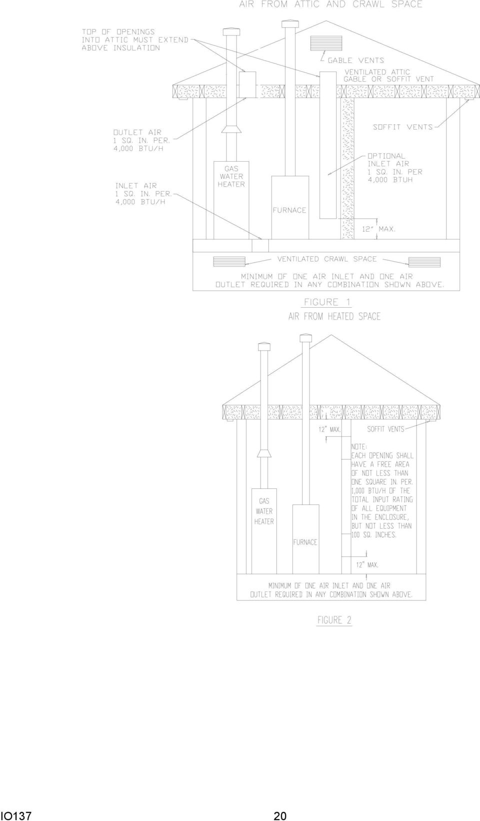
19 With a stiff wire brush on a flexible handle remove any loose scale from the heat exchanger at both the flue and burner openings. With a vacuum remove any loose scale dislodged and any additional debris found in the heat exchanger. Visually inspect the heat exchanger cells for any failures using a bright light. If any failures are discovered it is important to disable the furnace and notify the user to ensure that it remains inoperable until repairs are implemented. Reassemble the furnace in the reverse order. Note: No additional screws or wires are supplied with this product. All components must be reassembled to avoid an unsafe condition. Reconnect gas supply and check for leaks using a soap solution. If a flexible gas line is used examine it for cracks or weakness. Replace if necessary. Restore electrical power. Follow the lighting instructions to place the furnace into operation. SOURCE OF COMBUSTION AIR The recommended source of combustion air is the outdoor air supply. However, the use of indoor air in most applications is acceptable except as follows; 1. If the furnace is installed in a confined space it is recommended that the necessary combustion/ ventillation air originate via the attic, crawl space, or direct opening to the outside.. If indoor combustion is used, there must be no exposure to the substances. 3. The following installations may require OUTDOOR AIR for combustion, due to chemical exposures; Commercial buildings Buildings with indoor pools Furnaces installed in laundry rooms Furnaces installed in hobby or craft rooms Furnaces installed near chemical storage areas Exposures to the following substances in the combustion air supply may also require OUTDOOR AIR for combustion; Permanent wave solutions Chlorinated waxes and cleaners Chlorine based swimming pool chemicals De-icing salts or chemicals Carbon tetrachloride Halogen type refrigerants Masonry acid washing materials eners for clothes dryer Cleaning solvents (such as perchloroethylene) Printing inks, paint removers, varnishes, etc. Hydrochloric acid Cements and glues Antistatic fabric soft IO137 19

20 IO137
21 CLEARANCES FROM COMBUSTIBLE SURFACES VENT PIPE CLEARANCE TO COMBUSTIBLES 6 USING SINGLE WALL CONNECTOR OR 1 USING B-1 VENT ADEQUATE COMBUSTION / COMBUSTION AIR MUST BE SUPPLIED TO THE CLOSET. AIR FOR COMBUSTION OR VENTILATION MAY NOT BE TAKEN FROM BATHROOMS, BEDROOMS OR OTHER AREAS WHERE A DOOR MAY ISOLATE THAT ROOM. RETURN AIR DUCTS MUST BE COMPLETELY SELED TO THE FURNACE AND TERMINATE OUTSIDE THE ENCLOSURE. CLEARANCES TO COMBUSTIBLES FRONT 3 (4 RECOMMENDED FOR SERVICE) LEFT & RIGHT SIDE 1 TOP OF PLENUM 1 REAR FURNACE MUST BE COMPLETELY SEALED TO FLOOR OR BASE. COMBUSTION / VENTILATION AIR SUPPLY PIPES MUST TERMINATE 1 FROM TOP OF CLOSET AND 1 FROM FLOOR OF CLOSET. DO NOT REMOVE SOLID BASE PLATE FOR BOTTOM RETURN. IO137 1
22 VENT RETURN SUPPLY SUPPORT OR SUSPEND UNIT IN THREEE PLACES: LEFT, RIGHT, AND CENTER. RETURN AIR HORIZONTAL INSTALLATION VENT PIPE OPTIONAL NON-COMBUSTIBLE SUB BASE (SBM-XXX) NECESSARY WHEN INSTALLED ON COMBUSTIBLE FLOORING WITHOUT COOLING COIL SUPPLY AIR MAINTAIN PROPER CLEARANCES TO COMBUSTIBLES DOWNFLOW INSTALLATION IO137
23 ROTATION OF VENT BLOWER THE VENTER ASSEMBLY MAY BE ROTATED TO FIT THE VENTING REQUIREMENTS. REMOVE THE FOUR PERIMETER SCREWS, ROTATE THE VENTER TO THE DESIRED POSITION AND REINSERT AND TIGHTEN THE SCREWS. THE ORIFICE PLATE MUST BE ROTATED ALONG WITH THE VENTER ASSEMBLY FOR PROPER COMBUSTION AND IGNITION. A LOCATOR PIN IS PROVIDED FOR THIS PURPOSE. DO NOT USE SELF PIERCING SCREWS TO SECURE THE VENT TO THE PLASTIC CHIMNEY. USE A DRAFT HOOD CONNECTOR OR THE SELF DRILLING SCREWS SUPPLIED WITH THE FURNACE. LOCATING PIN VENTER SHOWN ROTATED IN THE LEFT VENTING POSITION. NOTE THE POSITION OF THE LOCATING PIN LOCATING PIN VENTER SHOWN IN THE (AS RECIEVED) VERTICAL VENT POSITION. NOTE THE POSITION OF THE LOCATING PIN. NOTE POSITION OF LOCATING PIN. VENTER SHOWN IN THE RIGHT SIDE VENT POSITION. NOTE POSITION OF LOCATING PIN. LOCATING PIN IO137 3
24 BLOWER OFF DELAY In the heating mode, the time period between the extinguishing of the burners and the circulating blower turning off, is known as the Blower Off Delay. This time is factory preset at 1 seconds. The 1 second delay can be changed to 1 or 9 seconds by changing the position of a jumper on the Ignition Control. HUMIDIFIER CONTROL The screw terminal on the ignition control called HUM is designed to give a 4 VAC signal to a humidistat in the heating mode. DO NOT USE ON HUMIDIFIERS WHICH USE 11 VAC. ELECTRONIC AIR CLEANER CONTROL The red-capped terminal on the ignition control marked EAC is to supply 11 VAC to an Electronic Air Cleaner. This terminal is powered in both the heating and air conditioning modes when the circulating blower is operating. IO137 4
25 GMP ONLY IO137
26 GMPE ONLY IO137 6
27 These instructions are also on the furnace LIGHTING INSTRUCTIONS FOR YOUR SAFETY READ BEFORE OPERATING A. This appliance does not have a pilot. It is equipped with an ignition device which automatically lights the burners. Do not try to light the burners by hand. B. BEFORE OPERATING smell around the appliance area for gas. Be sure to smell next to the floor because some gas is heavier than air and will settle on the floor. WHAT TO DO IF YOU SMELL GAS Do not try to light any appliance. Do not touch any electric switch; do not use any telephone in your building. Immediately call your supplier from a neighbor's phone. Follow the gas suppliers instructions. 1. STOP! Read the safety information above on this label.. Set the thermostat to lowest setting. 3. Turn off all electric power to the appliance. 4. This appliance is equipped with an automatic ignition system which automatically lights the burners. Do not try to light the burners by hand.. Remove control access panel. 6. Move the gas control switch or knob to "OFF". GAS CONTROL KNOB TO TURN OFF GAS TO APPLIANCE 1. Set the thermostat to its lowest setting.. Turn off all electric power to the appliance if service is to be performed. 3. Remove control access panel. If you do not follow these instructions exactly, a fire or explosion may result causing property damage, personal injury or loss of life. OPERATING INSTRUCTIONS GAS CONTROL SWITCH SHOWN IN "ON" POSITION If you cannot reach your gas supplier, call the fire department. C. Use only your hand to move the gas control switch or knob. Never use tools. If the gas control switch or knob will not operate, don't try to repair it, call a qualified service technician. Force or attempted repair may result in a fire or explosion. D. Do not use this appliance if any part has been under water. Immediately call a qualified service technician to inspect the appliance and to replace any part of the control system and any gas control which has been under water. 7. Wait five () minutes to clear out any gas. If you then smell gas, STOP! Follow "B" in the safety information above on this label. If you don't smell gas, go to the next step. 8. Move the gas control switch or knob to "ON". 9. Replace control access panel. 1. Turn on all electric power to the appliance. 11. Set the thermostat to the desired setting. 1. If the appliance will not operate, follow the instructions "To Turn Off Gas To Appliance" and call your service technician or gas supplier. GAS CONTROL SWITCH SHOWN IN "ON" POSITION 4. Move the gas control switch or knob to "OFF". Do not force.. Replace control access panel. WARNING: Improper installation, adjustment, alteration, service or maintenance can cause injury or property damage. Refer to the user's information manual provided with this furnace. For assqualified installer, ser- istance or additional information consult a vice agency or the gas supplier. This furnace must be installed in accordance with the manufacturers instructions and local codes. In the absence of local codes follow the National Fuel Gas Code, ANSI Z3.1. For indoor installation. PGB & PGJ For outdoor installation only. WARNING: If not ins- talled, operated and maintained in accordance with the manufacturer's instructions, this product could expose you to subst- ances in fuel combuscancer, birth defects tion which can cause death or serious illness and which are known to the State of California to cause or other reproductive harm. This product contains fiberglass insulation. Fiberglass insulation contains a chemical known by the State of California to cause cancer. FOR YOUR SAFETY Do not store or use gasoline or other flammable vapors and liquids in the vicinity of this or any other appliance. B IO137 7
28 EXTERIOR MASOY CHIMNEYS - CATEGORY I furnaces only. An exterior masonry chimney is defined as a Masonry chimney exposed to the outdoors on one or more sides below the roof line. The ability to use a clay lined masonry chimney depends on a parameter not associated with interior chimneys. This variable is the geographic location of the installation. Researchers have discovered that the winter design temperatures have a direct impact on the suitability of this type of venting. In most situations, except in some Gulf Coast areas and Southern California, the existing masonry chimneys will require a properly sized metallic liner. DEFINITION of TERMS Fan Assisted Combustion System - An appliance equipped with an integral mechanical means to either draw or force the products of combustion through the combustion chamber and/or the heat exchanger. FAN Min. - Refers to the minimum appliance input rating of a Category I appliance with a fan assisted combustion system that could be attached to the vent. FAN Max. - Refers to the maximum input rating of a Category I with a fan assisted combustion system that could be attached to the vent. NAT. Max. - Refers to the maximum appliance input of a Category I appliance equipped with a draft hood that could be attached to the vent. There are no minimum appliance ratings for draft hood equipped appliances. FAN + FAN - Refers to the maximum combined rating of two () or more fan assisted appliances attached to a common vent. FAN + NAT - Refers to the maximum combined input rating of one or more fan-assisted appliance and one or more draft hood equipped appliances attached to the common vent. NAT + NAT - Refers to the maximum combined input rating of two () or more draft hood equipped appliances attached to the common vent. NA - Means not applicable due to physical or geometric constraints. Vent - A passageway used to convey flue gases from gas utilization equipment, or their vent connectors, to the outside atmosphere. Vent Connector - The pipe or duct that connects a fuel-gas burning appliance to a vent or chimney. Flue Collar - That portion of an appliance designed for the attachment of a draft hood, vent connector or venting system. Categorized Vent Diameter - The minimum permissible vent diameter for Category I appliance to maintain a non-positive vent static pressure when tested according to nationally recognized standards. IO137 8
29 GENERAL VENTING REQUIREMENTS The requirements contained herein apply to both Category I draft hood equipped and fan assisted combustion appliances. At no time should a venting system listed for a Category II, III, or IV appliance be sized with these tables. The alternate sizing methods described in the National Fuel Gas Code (NFPA4/ANSI Z ) may also be used to size the venting system for a draft hood equipped appliance. At this time, alternate sizing methods have not been developed for fan assisted appliances. Therefore, until engineering data is developed to allow alternate sizing methods for Category I fan assisted appliances, the vent tables must be used. 1. The venting tables included in this instruction apply to vents and chimneys internal to the structure below the roof line. Exterior chimneys or vents not enclosed by the structure or chase below the roof line may experience continuous condensation depending on locality. Consult local gas utility, appliance manufacturer and/ or local codes. A chimney with one (1) or more sides exposed to the outside of the structure is considered to be an exterior chimney. A type B or listed chimney lining system passing through an unused masonry chimney flue is not considered to be exposed to the outdoors.. If the vent or connector size determined from the tables is smaller than the appliance draft hood outlet or flue collar, the smaller size may be used provided: a) The total vent height H is at least 1 ft. b) Vents or connectors for appliance outlets or flue collars 1 in diameter or smaller are not reduced more than one table size (e.g. 1 to 1 is a one size reduction). c) The maximum capacity listed in the tables for a fan assisted appliance is reduced by 1% (.9 X maximum capacity). d) The draft hood is greater than 4 in diameter. Do not connect a 3 diameter vent or connector to a 4 diameter draft hood outlet. THIS PROVISION DOES NOT APPLY TO FAN ASSISTED APPLIANCES. 3. Single appliance venting configurations with zero lateral lengths, Tables 1 &, are assumed to have no elbows in the vent system. For all other configurations, the vent system is assumed to have two () 9 o elbows. For each additional 9 o elbow or equivalent (two IO elbows are equivalent to one 9 o elbow) beyond two, the maximum capacity listed in the venting table should be reduced by 1% (.9 X maximum listed capacity). 4. The common venting Tables 3, 4, 7 & 8 were generated using a maximum horizontal vent connector length of 1 1/ feet (18 ) for each inch of connector diameter as follows; CONNECTOR DIA. MAXIMUM HORIZONTAL CONNECTOR LENGTH 3 inches 4 1/ feet 4 inches 6 feet inches 7 1/ feet 6 inches 9 feet 7 inches 1 1/ feet 8 inches 1 feet 9 inches 13 1/ feet 1 inches 1 feet The vent connector should be routed to the vent utilizing the shortest possible route. Connectors with longer horizontal lengths than those listed above are possible under the following conditions: a) The maximum capacity (FAN MAX. OR NAT MAX.) or the vent connector shall be reduced 1% for each additional multiple of the length listed above. For example, the maximum length listed above for a 4 inch connector is 6 feet. With a connector greater than 6 feet but not exceeding 1 feet the maximum capacity must be reduced by 1% (.9 X maximum vent connector capacity). With a vent connector length greater than 1 feet but not exceeding 18 feet, the maximum capac-
30 ity must be reduced by % (.8 X maximum vent capacity). b) The minimum capacity (FAN MIN.) shall be determined by referring to the corresponding single appliance table (tables 1 & ). In this case, for each appliance the entire vent connector and common vent from the appliance to the vent termination would be treated as a single appliance vent, as if the other appliances were not present.. If vent connectors are combined prior to entering the common vent, the maximum common vent capacity listed in the common vent tables must be reduced by 1%, the equivalent of one (1) 9 o elbow. `See figure 7. The horizontal length of the common vent connector or manifold (L) should not exceed 1 1/ feet (18 inches) for each inch of common vent diameter. 6. If the common vent is offset as shown in figure 8, the maximum common vent capacity listed in the common venting tables should be reduced by %, the equivalent of two () 9 elbows. The horizontal length of the offset shall not exceed 1 1/ feet for each inch of common vent diameter. 7. The common vent diameter must always be at least as large as the largest vent connector diameter. All interconnection fittings must also be the same size as the common vent. 8. Type B gas vents shall terminate above the roof surface with a listed cap or listed roof assembly according to their respective listing and the vent manufacture s instructions. VENT CAPS 1 AND SMALLER Listed gas venting systems using listed vent caps 1 and smaller may terminate according to the VENT TERMINATION TABLE. (See figure 1) LISTED CAP MINIMUM HEIGHT 8 MIN. LOWEST DISCHARGE OPENING THE VENT TERMINATION SHOULD NOT BE LESS THAN 8 FT. FROM A VERTICAL WALL FIGURE 1 -VENT CAPS 1 OR SMALLER GAS VENT TERMINATION TABLE ROOF PITCH MINIMUM HEIGHT FLAT T to 7 / 1 1. FEET * OVER 7 / 1 TO 8 / 1 1. FEET OVER 8 / 1 TO 9 / 1. FEET OVER 9 / 1 TO 1 / 1. FEET OVER 1 / 1 TO 11 / 1 3. FEET OVER 11 / 1 TO 1 / 1 4. FEET OVER 1 / 1 TO 14 / 1. FEET OVER 14 / 1 TO 16 / 1 6. FEET OVER 16 / 1 TO 18 / 1 7. FEET OVER 18 / 1 TO / 1 7. FEET OVER / 1 TO 1 / 1 8. FEET * This requirement covers most installations 9. Use sea level input rating when determining maximum capacity for high altitude installation. Use actual input rating for determining minimum capacity for high altitude installation. 1 X VERTICAL WALL 1. No portion of the vent system can extend into, or pass through any circulating air duct or plenum. 11. All vent pipe passing through floors, walls and ceilings must be installed with the listed clearance to combustible materials and be fire stopped according to local codes. In the absence of local codes refer to NFGC (Z3.1). 1. Vent connectors serving Category I appliances shall not be connected to any portion of mechanical draft systems operation under positive pressure such as Category III or IV Venting Systems. IO137 3
31 13. A Category I appliance must never be connected to a chimney servicing a solid fuel appliance. If fireplace chimney flue is used to vent this appliance, the fireplace opening must be permanently sealed. 14. A vent connector shall be supported without any dips or sags and shall slope a minimum of 1/4 per linear foot of connector, back towards the appliance. 1. Vent connector shall be firmly attached to draft hood outlets or flue collars by sheet metal screws or other approved means, except vent connectors of type B vent material that shall be assembled according to the manufacturer s instructions. Joints between sections of single wall connector pipes shall be fastened by sheet metal screws or other approved means. 16. When the vent connector used for Category I appliances must be located in or pass through a crawl space or other area which may be cold, that portion of the vent connector shall be of listed double wall type B vent material or material having equivalent insulation qualities. 17. The entire length of single wall metal vent connector shall be readily accessible for inspection, cleaning or replacement. 18. For appliances with more than one input rate, the minimum vent or connector (Fan - Min) capacity determined from the tables shall be less than the lowest input rating and the maximum vent or connector (Fan or Nat Max) capacity determined from the tables shall be greater than the highest appliance input rating. 19. For single appliance vents: a) If the vertical vent or tile lined chimney has a larger diameter or flow area than the vent connector, use the vertical vent diameter to determine the minimum vent capacity and vent connector diameter to determine the maximum vent capacity. The flow area of the vertical, however, shall not exceed 7 times the flow area IO of the listed appliance categorized vent area, draft hood outlet area or flue collar area unless designed according to approved engineering methods. See table 9 for calculated areas. For multiple appliance vents: b) The flow area of the largest section of a vertical vent or chimney shall not exceed 7 times the smallest listed appliance categorized vent area, flue area, or draft hood outlet area unless designed according to approved engineering methods. See table for calculated areas. Maximum vent or tile lined chimney flow area = TT(D*) X 7 4 *Draft hood outlet diameter, flue collar diameter or listed appliance categorized vent diameter. c) In no case, shall the vent connector be upsized more than consecutive table size diameters over the size of the draft hood outlet, flue collar or listed categorized vent. Example: An appliance with a 4 inch diameter flue outlet collar or draft hood connector cannot be vented with a connector larger than 6 inches.. Masonry chimneys used to vent Category I central furnaces must either be tile lined or lined with a listed metal lining system or dedicated gas vent. Unlined chimneys are prohibited. (See note 1) 1. A fan assisted furnace may be common vented into an existing chimney provided; a) The chimney is currently serving at least one draft hood appliance. SINGLE APPLIANCE VENTING OF A FAN ASSISTED FURNACE INTO A TILE LINED, MASOY CHIMNEY IS PROHIBITED. THE CHIMNEY MUST FIRST BE LINED WITH EITHER TYPE B VENT SIZED IN ACCORDANCE WITH TABLES 1 OR OR A LISTED SINGLE WALL, METAL LINING SYSTEM, SIZED IN ACCORDANCE WITH NOTE.
32 . Listed, corrugated metallic chimney liner systems in masonry chimneys shall be sized by using tables 3 or 4 for common venting with the maximum capacity reduced by % (.8 X maximum capacity) and the minimum capacity shown in the applicable table. Corrugated metal vent systems installed with bends or offsets require additional reduction of the vent maximum capacity (See note 6). 3. For multiple units of gas utilization equipment all located on one floor, available total height H is measured from the highest draft hood outlet or flue collar up to the level of the cap or terminal. Connector rise R is taken from the measured outlet or flue collar to the level where the vent gas streams come together. (Not applicable for multi-story). 4. For multi-story installations, available total height for each segment of the system H is the vertical distance between the draft hood outlet or flue collar entering that segment and the centerline of the next higher interconnection tee (See Figure 13).. The size of the lowest connector and of the vertical vent leading to the lowest interconnection of a multi-story system must be according to table 1 or, for available total height H up to the lowers connection (See figure 14). 6. Common vents in multi-story systems should be type B and have no offsets. 7. Numbers followed by an asterisk(*) in Table & 6, indicate the possibility of continuous condensation, depending upon locality. Consult appliance manufacturer, local serving gas supplier, and/or authority having jurisdiction. 8. In a single run of vent or vent connector, more than one diameter and type of pipe are permitted to be used, provided that all the sizes are permitted by the tables. 9. If the desired vent height and connector rise and/or lateral are between the table entries, linear interpolation is permitted for calculation of the permissible appliance input ratings. Extrapolation beyond the table entries is not recommended. 3. All combinations of pipe sizes, single wall, and double wall metal pipe are allowed within any connector run(s) or within the common vent provided ALL of the appropriate tables permit All of the desired sizes and type of pipe, as if they were used for the entire length of the subject connector vent. If a single wall and type B double wall pipe are used for vent connectors, the common vent must be sized using table Locate the draft hood outlet or flue collar of the smallest input appliance closest to or under the common vent. 3. When the vent table permits more than one diameter of pipe to be used for a connector or vent, the smallest permitted diameter should be preferred. IO137 3
33 EXAMPLES USING SINGLE APPLIANCE VENTING TABLE Single Fan Assisted Appliance Suppose an installer has an 8, Btu / hr. input fan assisted appliance that must be installed using 1 ft. of lateral connector attached to a 3 ft. high Type B vent. Two 9 elbows are needed for the installation. Can a single wall metal vent connector be used for this installation? Solution -Table refers to the use of single wall metal vent connectors with Type B vent. In the first column find the row associated with a 3ft. height and a 1 ft. lateral. Read across this row, looking at the Fan Min and Fan Max columns, to find that a 3 diameter single wall metal connector is not recommended. Moving to the next larger size single wall connector (4 ) we find that a 4 diameter single wall connector has a recommended maximum vent capacity of 91, Btu / hr. and a recommended maximum vent capacity of 144, Btu / hr. The 8, Btu / hr. fan assisted appliance is outside this range, so we conclude that a single wall connector cannot be used to vent this appliance using 1ft. of lateral for the connector. However, we see that if the 8, Btu / hr. input appliance could be moved within ft. of the vertical vent, then a 4 single wall metal connector could be used for this appliance. Table shows the acceptable range of vent capacities for a 4 vent with ft. of lateral to be between 7, Btu / hr. and 17, Btu / hr. If the appliance cannot be moved closer to the vertical vent, then Type B vent could be used as the connector material. In this case, Table 1 shows that for a 3ft. high vent with 1ft. of lateral, the acceptable range of vent capacities for a 4 diameter vent attached to a fan assisted appliance are between 37, Btu / hr. and 1, Btu / hr. Common Venting a Draft Hood Water Heater with a Fan Assisted Furnace In this case, a 3, Btu / hr draft hood equipped water heater with a ft. connector rise is to be common vented with a 1, Btu / hr fan assisted furnace with a 3ft. connector rise. The common vent consists of a 3ft rise of type B vent. What are the recommended vent diameters for each connector and the common vent? Solution-TABLE 4 Water Heater vent connector diameter - Let us assume the installer would like to use a single wall metal vent connector. Using table 4, Vent Connector Capacity, read down the total vent height H column to 3ft. and read across the ft. connector rise R row to the first Btu / hr rating in the Nat Max column that is equal to or greater than the water heater input rating. The table shows that a 3 connector has a maximum input rating of 37, Btu / hr. Since this is greater than the water heater input rating, a 3 vent connector is adequate. Furthermore, since the water heater is equipped with a draft hood, there are no minimum input rating restrictions. Furnace vent connector diameter - Again, let us assume the installer would like to use a single wall vent connector. Using table 4, Vent connector capacity, read down the total vent height H column to 3ft. and across the 3ft. connector rise R row. Since the furnace has a fan assisted combustion system, find the first Fan Max column with a Btu / hr rating greater than the furnace input rating. The 4 vent connector has a maximum input rating of 119, Btu / hr and a minimum input rating of 8, Btu / hr. The 1, Btu / hr furnace in this example falls within this range, so a 4 connector is adequate. If the furnace would have had an input rating of 8, Btu / hr, than a type B vent connector (see Table 3) would have to be used to meet the minimum capacity limit. IO-137H 33
34 Common vent diameter - The total input to the common vent is 13, Btu / hr. Using Table 4, common vent capacity, read down the total vent height H column to 3ft and across this row to find the smallest vent diameter in the Fan + Nat column that has a Btu / hr rating equal to or greater than 13, Btu / hr. The 4 common vent has a capacity of 13, Btu / hr and the common vent has a capacity of, Btu / hr. Therefore, the common vent should be used in this example. Summary - In this example, the installer may use a 3 diameter single wall metal vent connector for the water heater and a 4 single wall metal vent connector for the furnace. The common vent should be a diameter type B vent. Common Venting into a Masonry Chimney - In this case, a 3, Btu / hr input 4 diameter draft hood equipped water heater with ft of connector rise and 4ft of horizontal length is to be common vented with a 1, Btu / hr fan assisted furnace with a 4 diameter flue collar, 3ft of connector rise and 6ft of horizontal length. The common vent is an 8 X 1 tile lined chimney that is 3ft tall. What are the recommended vent diameters for each connector? Is this an acceptable installation? Solution- Table 8 is used to size common venting installations involving single wall connectors into masonry chimneys. Water heater vent connector diameter - Using Table 8, vent connector capacity, read down the total vent height H column to 3ft and read across the ft connector rise R row to the first Btu / hr rating in the Nat Max column that is equal to or greater than the water heater input rating. The table shows that a 3 vent connector has a maximum input of only 31, Btu / hr while a 4 vent connector has a maximum input of 7, Btu / hr. A 4 vent connector must therefore be used. Furnace vent connector diameter - Using table 8 vent connector capacity, read down the total vent height H column to 3ft and across the 3ft connector rise R row. Since the furnace has a fan assisted combustion system, find the first Fan Max column with a Btu / hr rating greater than the furnace input rating. The 4 vent connector has a maximum input rating of 17, Btu / hr and a minimum input rating of 9, Btu / hr. The 1, Btu / hr furnace in this example falls within this range, so a 4 connector is adequate. Masonry Chimney - From Table 9, the equivalent area for a nominal liner size of 8 X 1 is 63.6 sq. in. Using Table 8, common venting capacity, read down the Fan + Nat column under the minimum internal area of chimney value of 63 to the row for 3ft height to find a capacity value of 739, Btu / hr. The combined input rating of the furnace and water heater of 13, Btu / hr, is less than the table value, so this is an acceptable installation. Note 19 requires the common vent area to be no greater than 7 times the flow area of the smallest appliance outlet area. Both appliances in this installation use 4 diameter outlets. From Table 9, the equivalent area for an inside diameter of 4 is 1. sq. in. Seven times 1. is 8.4, which is greater than 63.6, so this configuration is acceptable. Note 1 specifies that table values are for vents or chimneys that are not exposed to the outdoors below the roof line. If the masonry chimney in this case were exposed below the roofline, then the appliance manufacturer, local gas utility, and/or authority having jurisdiction must be consulted. IO137 34
35 TYPICAL VENTING APPLICATIONS IO137 3
36 TABLE 9 Masonry Chimney Liner Dimensions With Circular Equivalents Nominal Liner Size - Inches Inside Dimensions In Liner - Inches Inside Diameter or Equivalent Diameter - Inches Equivalent Area Square Inches 4 x 8 1/ x 6 1/ x 8 6 3/4 x 6 3/ x 1 6 1/ x 1 1/ x 1 9 3/4 x 9 3/ x / x 13 1/ x /4 x 13 1/ x 13 x x 16 3/4 x 16 3/ x / x 1/ When liner sizes differ dimensionally from those shown in Table 9 equivalent diameters may be from published tables for square and rectangular ducts of equivalent carrying capacity or by other engineering methods. IO137 36
37 IO137 37
38 IO VENT TABLES Capacity of Type B Double-Wall Vents with Type B Double-Wall Connectors Serving a Single Category I Appliance TABLE 1 Vent and Connector Diameter - D (inches) Height Lateral Appliance Input Rating in Thousands of Btu Per Hour H L FAN NAT FAN NAT FAN NAT FAN NAT FAN NAT FAN NAT (ft) (ft) Min Max Max Min Max Max Min Max Max Min Max Max Min Max Max Min Max Max
39 IO VENT TABLES Capacity of Type B Double-Wall Vents with Single-Wall Metal Connectors Serving a Single Category I Appliance TABLE Vent and Connector Diameter - D (inches) Height Lateral Appliance Input Rating in Thousands of Btu Per Hour H L FAN NAT FAN NAT FAN NAT FAN NAT FAN NAT FAN NAT FAN NAT FAN NAT (ft) (ft) Min Max Max Min Max Max Min Max Max Min Max Max Min Max Max Min Max Max Min Max Max Min Max Max
40 TABLE 3 Vent Connector Capacity Vent Connector Height Rise VENT TABLES Capacity of Type B Double-Wall Vents with Type B Double-Wall Connectors Serving Two or more Category I Appliances Vent Connector Diameter - D (inches) Appliance Input Rating Limits in Thousands of Btu Per Hour H R FAN NAT FAN NAT FAN NAT FAN NAT FAN NAT FAN NAT FAN NAT (ft) (ft) Min Max Max Min Max Max Min Max Max Min Max Max Min Max Max Min Max Max Min Max Max Common Vent Capacity Common Vent Diameter - D (inches) Vent Height Combined Appliance Input Rating in Thousands of Btu Per Hour H FAN FAN NAT FAN FAN NAT FAN FAN NAT FAN FAN NAT FAN FAN NAT FAN FAN NAT (ft) +FAN +NAT +NAT +FAN +NAT +NAT +FAN +NAT +NAT +FAN +NAT +NAT +FAN +NAT +NAT +FAN +NAT +NAT IO137 4
41 VENT TABLES Capacity of Type B Double-Wall Vent with Single-Wall Connectors Serving Two or more Category I Appliances TABLE 4 Vent Connector Capacity Vent Connector Diameter - D (inches) Vent Connector Appliance Input Rating Limits in Thousands of Btu Per Hour Height Rise H R FAN NAT FAN NAT FAN NAT FAN NAT FAN NAT FAN NAT FAN NAT (ft) (ft) Min Max Max Min Max Max Min Max Max Min Max Max Min Max Max Min Max Max Min Max Max Common Vent Capacity Common Vent Diameter - D (inches) Vent Height Combined Appliance Input Rating in Thousands of Btu Per Hour H FAN FAN NAT FAN FAN NAT FAN FAN NAT FAN FAN NAT FAN FAN NAT FAN FAN NAT (ft) +FAN +NAT +NAT +FAN +NAT +NAT +FAN +NAT +NAT +FAN +NAT +NAT +FAN +NAT +NAT +FAN +NAT +NAT IO137 41
42 TABLE HEIGHT LATERAL VENT TABLES Capacity of Masonry Chimney with Type B Double-Wall Vent Connectors Serving a Single Category I Appliance Connector Diameter - D (inches) To be used with chimney areas within the size limits at bottom Appliance Input Rating in Thousands of Btu Per Hour H L FAN NAT FAN NAT FAN NAT FAN NAT FAN NAT FAN NAT FAN NAT FAN NAT FAN NAT (ft) (ft) Min Max Max Min Max Max Min Max Max Min Max Max Min Max Max Min Max Max Min Max Max Min Max Max Min Max Max Minimum Internal Area of Chimney Square Inches Max Internal Area of Chimney Square Inches * SEE NOTE 7 * 31 8* * 3* 33* 8* 38* 36* 41* * 67 6 * 48* 74 68* 6* 8* 76* 67* 9* * * 97* 83* * 11* 17* 91* 161* 11* 138* 17* * * 171* 19* 1* 3* 1* 199* 18* * 7* 188* 31* 33* 34* 8* 64* * * 4* 376* 37* * 11* 468* * 63*
43 VENT TABLES Capacity of Masonry Chimney with Single-Wall Vent Connectors TABLE 6 Serving a Single Category I Appliance Connector Diameter - D (inches) To be used with chimney areas within the size limits at bottom Appliance Input Rating in Thousands of Btu Per Hour HEIGHT LATERAL H L FAN NAT FAN NAT FAN NAT FAN NAT FAN NAT FAN NAT FAN NAT FAN NAT FAN NAT (ft) (ft) Min Max Max Min Max Max Min Max Max Min Max Max Min Max Max Min Max Max Min Max Max Min Max Max Min Max Max Minimum Internal Area of Chimney Square Inches Maximum Internal Area of Chimney Square Inches * SEE NOTE 7 * 31 8* 4* 3* 3* 7* 38* 3* 41* * * 46* 73 67* 9* 81* 7* 66* 91* * * 9* 8* * 113* 1* 88* 16* 149* 136* 14* * * 168* 1* * 8* 1* 19* 18* * 3* 18* 3* 31* 31* 78* 8* * * 39* 37* 318* * 4* 48* * 61* IO137 43
44 VENT TABLES Capacity of Masonry Chimney with Type B Double-Wall Connectors Serving Two or More Category I Appliance TABLE 7 Vent Connector Capacity Vent Connector Diameter - D (inches) Vent Connector Appliance Input Rating Limits in Thousands of Btu Per Hour Height Rise H R FAN NAT FAN NAT FAN NAT FAN NAT FAN NAT FAN NAT FAN NAT (ft) (ft) Min Max Max Min Max Max Min Max Max Min Max Max Min Max Max Min Max Max Min Max Max Common Vent Capacity Minimum Internal Area of Chimney, Square Inches Vent Height Combined Appliance Input Rating in Thousands of Btu Per Hour H FAN FAN NAT FAN FAN NAT FAN FAN NAT FAN FAN NAT FAN FAN NAT FAN FAN NAT (ft) +FAN +NAT +NAT +FAN +NAT +NAT +FAN +NAT +NAT +FAN +NAT +NAT +FAN +NAT +NAT +FAN +NAT +NAT IO137 44
45 VENT TABLES Capacity of Masonry Chimney with Type B Double-Wall Connectors Serving Two or More Category I Appliances TABLE 8 Vent Connector Capacity Type B Double-Wall Vent Connector Diameter - D (inches) Vent Connector Appliance Input Rating Limits in Thousands of Btu Per Hour Height Rise H R FAN NAT FAN NAT FAN NAT FAN NAT FAN NAT FAN NAT (ft) (ft) Min Max Max Min Max Max Min Max Max Min Max Max Min Max Max Min Max Max Common Vent Capacity Minimum Internal Area of Masonry Chimney Flue (Square Inch) Vent Height Combined Appliance Input Rating in Thousands of Btu Per Hour H FAN FAN NAT FAN FAN NAT FAN FAN NAT FAN FAN NAT FAN FAN NAT FAN FAN NAT (ft) +FAN +NAT +NAT +FAN +NAT +NAT +FAN +NAT +NAT +FAN +NAT +NAT +FAN +NAT +NAT +FAN +NAT +NAT
Your safety and the safety of others are very important.
 NATURAL GAS TO PROPANE CONVERSION KIT 090 INSTALLATION INSTRUCTIONS FOR ALTITUDES 0 -,00 FT. ONLY PROPANE CONVERSION KIT SAFETY... INSTALLATION REQUIREMENTS... Tools and Parts... LP Gas Requirements...
SL280UHV SERIES GAS FURNACE WARNING
 2010 Lennox Industries Inc. Dallas, Texas, USA 506677 01 11/2010 Supersedes 506409 01 SL280UHV SERIES GAS FURNACE Litho U.S.A. FIRE OR EXPLOSION HAZARD. Failure to follow safety warnings exactly could
USER S, MAINTENANCE and SERVICE INFORMATION MANUAL
 CONTENTS SAFETY INFORMATION................ 2 FOR YOUR SAFETY....................... 2 SYSTEM OPERATION.................. 2 THERMOSTATS........................... 2 INTERMITTENT IGNITION DEVICE...........
CROWN BOILER COMPANY BWF SERIES BOILER CATEGORY I VENT KIT INSTALLATION AND OPERATING INSTRUCTIONS
 CROWN BOILER COMPANY BWF SERIES BOILER CATEGORY I VENT KIT INSTALLATION AND OPERATING INSTRUCTIONS WARNING Improper installation, adjustment, alteration, service, or maintenance of this product can cause
USER S INFORMATION MANUAL
 USER S INFORMATION MANUAL UPFLOW, DOWNFLOW, UPFLOW/HORIZONTAL & HORIZONTAL ONLY INDUCED DRAFT GAS FURNACES Recognize this symbol as an indication of Important Safety Information If the information in this
36G22, 36G23, 36G24 & 36G52 36J22, 36J23, 36J24 & 36J52 DSI and HSI Single Stage Combination Gas Valve
 Operator: Save these instructions for future use! FAILURE TO READ AND FOLLOW ALL INSTRUCTIONS CAREFULLY BEFORE INSTALLING OR OPERATING THIS CONTROL COULD CAUSE PERSONAL INJURY AND/OR PROPERTY DAMAGE. DESCRIPTION
CARING FOR YOUR WATER HEATER
 http://waterheatertimer.org/troubleshoot-rheem-tankless-water-heater.html Water Heater Inspections CARING FOR YOUR WATER HEATER Venting System (Direct Vent Only) The venting system should be inspected
Tankless Water Heater
 Tankless Water Heater USER S INFORMATION MANUAL Models WGRTNG199 / WGRTLP199 WGRTCNG199 / WGRTCLP199 NOTICE: Westinghouse reserves the right to make product changes or updates without notice and will not
ASX7-4-IOM-7 J30-08579
 INSTALLATION INSTRUCTIONS 4" COMBUSTION AIR INLET KIT TUBULAR GAS FIRED DIRECT SPARK PROPELLER UNIT HEATERS UNIT CONVERSION & CATEGORY III VENTING FOR SEPARATED COMBUSTION For 30,000 to 75,000 BTU/HR SUPPLEMENT
THC 85 INDUSTRIAL / COMMERCIAL SPACE HEATER
 THC 85 INDUSTRIAL / COMMERCIAL SPACE HEATER Certified to / Certifié à CGA 2.14 M2000 Conforms to / Conforme à ANSI std Z83.7 2000 Suitable for indoor or outdoor installation / Unvented / Unattended Type
LPM-06 CONVERSION KIT
 LPM-06 CONVERSION KIT TWO-STAGE FURNACE NATURAL GAS TO L.P. GAS CONVERSION Goodman Manufacturing Company, L.P. 2009-2011 5151 San Felipe, Suite 500, Houston, TX 77056 www.goodmanmfg.com -or- www.amana-hac.com
Arapahoe County Residential Water Heater Installation and Inspection Guide
 Arapahoe County Residential Water Heater Installation and Inspection Guide The attached handout is designed to be a general permit submittal and inspection guide covering most installation instances, however
TECHNICAL MANUAL GDS8 & GHS8
 TECHNICAL MANUAL AL GDS8 & GHS8 33-3/8" 80% Gas Furnace Units Refer to Service Manual RS6610004 for installation, operation, and troubleshooting information. All safety information must be followed as
Cooling Capacity CFM range @.5 in. w.c. (125 Pa)
") N8MXL Product Specifications 80% ECM Single Stage Heating Furnace EASIER TO SELL 80% AFUE Flame roll out sensors standard Category I venting Blocked vent switch 24 VAC humidifier terminal Electronic air
N8MXL Product Specifications 80% ECM Single Stage Heating Furnace EASIER TO SELL 80% AFUE Flame roll out sensors standard Category I venting Blocked vent switch 24 VAC humidifier terminal Electronic air
Evaluate, Clean, and Tune Guidance
 Evaluate, Clean, and Tune Guidance The Evaluate, Clean and Tune (ECT) process serves three essential purposes in the Weatherization Assistance Program (WAP). The first is to evaluate the existing system
INSTALLATION AND OPERATIONS GUIDE FOR GRAND CANYON GAS LOG SYSTEMS
 INSTALLATION AND OPERATIONS GUIDE FOR GRAND CANYON GAS LOG SYSTEMS Installation and service must be provided by a qualified installer, service agency or gas supplier Grand Canyon Gas Logs, logs are made
PART 6: VENTING, COMBUSTION AIR & CONDENSATE REMOVAL
 PART 6: VENTING, COMBUSTION AIR & CONDENSATE REMOVAL Boiler Manual A. INSTALLING EXHAUST VENT AND INTAKE AIR VENT B. GENERAL n DANGER The Elite Heating Boiler must be vented as detailed in this section.
TB-A028-06 - A. O. SMITH - FVIR INTELLI-VENT TROUBLESHOOTING CHART # LED STATUS PROBLEM SOLUTION
 1 2 3 4 5 Inadequate or no earth ground sensed by the Intelli-Vent control. Power supply to Intelli-Vent control has reversed polarity. Pressure switch circuit remaining closed for more than 5 seconds
Propane Conversion Kit PROPANE CONVERSION KIT INSTALLATION MANUAL
 Propane Conversion Kit Supersedes: 145.25-IOM2 (708) Form 145.25-IOM2 (908) PROPANE CONVERSION KIT INSTALLATION MANUAL "LPKIT " - PROPANE CONVERSION KIT Kits are available for field conversion from natural
Owner Retain this manual in a safe place to provide your serviceman information if it becomes necessary.
 INSTALLATION, OPERATING AND SERVICE MANUAL FOR EASY RADIANT WORKS HEATWAVE MODEL GH-25-40 GAS FIRED, VENTED INFRARED TUBE HEATER FOR RESIDENTIAL & COMMERCIAL / INDUSTRIAL APPLICATIONS. For Your Safety
Applies to: Models F, B, FE, and BE FOR YOUR SAFETY
 Form CP-F/B-GC (Version A.2) Obsoletes Form CP-F/B-GC (Version A) Gas Conversion Kits and Instructions Applies to: Models F, B, FE, and BE Model B Model F All gas conversion must be done by a qualified
Your safety and the safety of others are very important.
 NATURAL GAS TO PROPANE CONVERSION KIT ALPKT7- INSTALLATION INSTRUCTIONS PROPANE CONVERSION KIT SAFETY... INSTALLATION REQUIREMENTS... Tools and Parts... LP Gas Requirements... INSTALLATION INSTRUCTIONS...
Operator: Save these instructions for future use!
 WHITE-RODGERS 36C01 Combination Gas Valves (24 Volt and 120 Volt Models) INSTALLATI INSTRUCTIS FAILURE TO READ AND FOLLOW ALL INSTRUCTIS CAREFULLY BEFORE INSTALLING OR OPERATING THIS CTROL COULD CAUSE
Instruction Manual for Residential Manufactured Home Gas Water Heaters
 Instruction Manual for Residential Manufactured Home Gas Water Heaters FOR USE ONLY IN MANUFACTURED HOMES GAMA certification applies to all residential gas water heaters with capacities of 20 to 100 gallons
Owner s Manual 58HDX UPFLOW / HORIZONTAL / DOWNFLOW HIGH EFFICIENCY GAS FURNACE. ama ! WARNING SAFETY CONSIDERATIONS
 UPFLOW / HORIZONTAL / DOWNFLOW HIGH EFFICIENCY GAS FURNACE Owner s Manual NOTE TO INSTALLER: THIS MANUAL MUST BE LEFT WITH THE EQUIPMENT USER. USER: Please read all instructions in the manual and retain
BC & BCH SERIES INDOOR / OUTDOOR INSTALLATION
 Air Conditioning Central Heating & Cooling BC & BCH SERIES INDOOR / OUTDOOR INSTALLATION INSTALLATION AND SERVICE MANUAL 2 PROJECT: ADDRESS: MODEL: SERIAL NUMBER: INSTALLER: ADDRESS: PHONE NUMBER: INSTALLATION
G670 Intermittent Pilot Ignition Controls
 Installation Sheets Manual 121 Gas Combustion Combination Controls and Systems Section G Technical Bulletin Issue Date 0300 Intermittent Pilot Ignition Controls Figure 1: Intermittent Pilot Ignition Control
Commercial Gas Furnace Upflow
 Commercial Gas Furnace Upflow Model G24-200 80% A.F.U.E. 200,000 Btuh Input Heating Cap. 7.5 or 10 Tons Nominal Add-On Cooling GUK FEATURES Certified by A.G.A./C.G.A. Laboratories. Heavy gauge painted
Heating, Ventilation, Air Conditioning and Refrigeration (HVACR)
") Heating, Ventilation, Air Conditioning and Refrigeration (HVACR) I. Demonstrate safety skills in typical HVACR work situations to NATE Core Installer Knowledge Areas for Technician Excellence for Safety
Heating, Ventilation, Air Conditioning and Refrigeration (HVACR) I. Demonstrate safety skills in typical HVACR work situations to NATE Core Installer Knowledge Areas for Technician Excellence for Safety
M7RL Series TECHNICAL SPECIFICATIONS. FEATURES and BENEFITS. High Efficiency / Direct Vent Condensing Downflow Gas Furnace
 TECHNICAL SPECIFICATIONS M7RL Series High Efficiency / Direct Vent Condensing Downflow Gas Furnace Induced Draft - 9%+ AFUE Input 4,000 thru 7,000 Btuh The high efficiency downflow gas furnace is especially
GAS SAFETY PRECAUTIONS
 GAS SAFETY PRECAUTIONS Instructions on what to do when a user smells gas can be obtained from the local gas supplier. These instructions must be posted in a prominent location where the unit is to be operated.
Instruction Manual for Residential Gas Water Heaters
 Instruction Manual for Residential Gas Water Heaters NOT FOR USE IN MANUFACTURED (MOBILE) HOMES GAMA certification applies to all residential gas water heaters with capacities of 20 to 100 gallons with
Gas-Fired, Residential Storage Type Water Heaters
 Consulting, Resource, Education, Training, and Support Services for Home Inspectors A candle loses no light when it lights another candle. Gas-Fired, Residential Storage Type Water Heaters Most inspectors
SWIMMING POOL HEAT PUMP
 SWIMMING POOL HEAT PUMP Installation & User Manual Model HP40B HP50B HP65B Hayward Pool Products Canada, Inc. T: 1-888-238-7665 www.haywardpool.ca CONTENT I. Application 4 II. Features 4 III. Technical
G26 Corp. 9721-L11 Revised 07-2001 LENNOXOEMPARTS.COM. Service Literature G26 SERIES UNITS
 Service Literature G26 SERIES UNITS G26 series units are high-efficiency upflow gas furnaces manufactured with DuralokPlust aluminized steel clamshell-type heat exchangers. G26 units are available in heating
SECTION 23 81 03 - PACKAGED ROOFTOP AIR CONDITIONING UNITS NON-CUSTOM
 SECTION 23 81 03 - PACKAGED ROOFTOP AIR CONDITIONING UNITS NON-CUSTOM PART 1 - GENERAL 1.1 SUMMARY A. Section Includes: 1. Packaged rooftop air conditioning unit (5 tons and smaller). 2. Roof curb. 1.2
Installation Instructions for Alarm Module Kit A043F059
 Instruction Sheet 07-2013 Installation Instructions for Alarm Module Kit A043F059 1 Introduction The information contained within is based on information available at the time of going to print. In line
Dennis Fire Department Fire Prevention Mark Dellner Fire Chief
 Dennis Fire Department Fire Prevention Mark Dellner Fire Chief FIRE SAFETY INSPECTION GUIDELINES FOR COMMERCIAL PROPERTIES (MA Fire Prevention Regulations 527 CMR, MGL Chapter 148) FIRE PREVENTION CHECKLIST-
San josé OWNER S MANUAL
 San josé OWNER S MANUAL Assembling & operating manual San josé 30 mbar - PORTABLE GAS BARBECUE 1. 2. 3. Improper installation, adjustment, alteration, service or maintenance can injury or property damage.
COMMERCIAL COOKING HOODS, VENTILATION & FIRE SUPPRESSION SYSTEM GUIDELINES AND PROCEDURES
 COMMERCIAL COOKING HOODS, VENTILATION & FIRE SUPPRESSION SYSTEM GUIDELINES AND PROCEDURES These guidelines are to be used for ALL commercial cooking hoods, ventilation systems and related fire suppression
INSTALLATION INSTRUCTIONS Fan Coil Replacement Coil Kit EBX & EBXX
 Fan Coil Replacement Coil Kit EBX & EBXX These instructions must be read and understood completely before attempting installation. These instructions covers the installation of replacement coil kit into
prestige Condensing Water Boiler SERVICE TECHNICIAN S TROUBLE SHOOTING GUIDE 2008-36 TSG-PRESTIGE Date revised: 12/6/10
 prestige Condensing Water Boiler SERVICE TECHNICIAN S TROUBLE SHOOTING GUIDE Date revised: 12/6/10 2008-36 TSG-PRESTIGE Table of Contents INTRODUCTION Page 1-2 SERVICING TIPS AND INSTRUCTIONS Page 3-4
Subpart 1. Installation. All plumbing systems must be. installed and tested according to this chapter and chapter 4715,
 4658.4500 PLUMBING SYSTEMS; NEW CONSTRUCTION. Subpart 1. Installation. All plumbing systems must be installed and tested according to this chapter and chapter 4715, the Minnesota Plumbing Code. Subp. 2.
TECHNICAL GUIDE 95.5% SINGLE STAGE GAS-FIRED RESIDENTIAL MULTI-POSITION GAS FURNACES MODELS: TG9S DESCRIPTION FEATURES
 TECHNICAL GUIDE 95.5% SINGLE STAGE GAS-FIRED RESIDENTIAL MULTI-POSITION GAS FURNACES MODELS: TG9S NATURAL GAS 40-130 MBH INPUT Due to continuous product improvement, specifications are subject to change
GROWTH MANAGEMENT DEPARTMENT 201 SE 3 rd ST, (Second Floor), Ocala, FL 34471 (352) 629-8421; FAX: (352) 629-8264
, Ocala, FL 34471 (352) 629-8421; FAX: (352) 629-8264") BUILDING CODE GUIDELINE FOR MECHANICAL INSPECTIONS Building Code compliance is the obligation of design professionals and/or contractors. Plan Review and Inspection Guidelines are intended to be used by
BUILDING CODE GUIDELINE FOR MECHANICAL INSPECTIONS Building Code compliance is the obligation of design professionals and/or contractors. Plan Review and Inspection Guidelines are intended to be used by
STATE OF FLORIDA HOME INSPECTION STANDARDS OF PRACTICE:
 STATE OF FLORIDA HOME INSPECTION STANDARDS OF PRACTICE: 61-30.801 Standards of Practice, General. (1) Home inspections performed to these Standards of Practice are intended to provide the client with information
Air Conditioning Sign-Off Sheet
 Air Conditioning Sign-Off Sheet Printed Technician Name Address Social Security Number Telephone Number City State Zip Code Install Or Verify The Accuracy Of An Air Conditioner s Installation The candidate
DIRECT VENT GAS FURNACE FOR THROUGH THE WALL OR WINDOW INSTALLATION
 DIRECT VENT GAS FURNACE FOR THROUGH THE WALL OR WINDOW INSTALLATION OWNER'S OPERATION AND INSTALLATION MANUAL SA25N SA25P SA40N SA40P WARNING: If the information in these instructions is not followed exactly,
Instantaneous gas water heater
 Instantaneous gas water heater Models W 125...T1 installation operation maintenance The Bosch instantaneous water heater is a high efficiency, space saving answer to your water heating needs. All Bosch
2010 Residential Water Heater Replacement Check List
 2010 Residential Water Heater Replacement Check List The intent of this check list is to provide installers a general reference for the enforcement of code requirements in the Greater San Diego Area. This
orlando OWNER S MANUAL
 orlando OWNER S MANUAL 2 Assembling & operating manual Orlando 30 mbar - PORTABLE GAS BARBECUE 1. 2. 3. Improper installation, adjustment, alteration, service or maintenance can injury or property damage.
Chromalox. Installation, Operation. Portable Industrial Unit Blower Air Heater Type DRA RENEWAL PARTS IDENTIFICATION
 Chromalox Installation, Operation RENEWAL PARTS IDENTIFICATION Portable Industrial Unit Blower Air Type DRA and DIVISION SALES REFERENCE DATE SECTION (Supersedes P-) PF-) NOVEMBER, 00 DRA PF- -0-00 Specifications
INSTALLATION, OPERATION, AND SERVICE MANUAL RESIDENTIAL STORAGE TYPE GAS WATER HEATER
 INSTALLATION, OPERATION, AND SERVICE MANUAL RESIDENTIAL STORAGE TYPE GAS WATER HEATER THESE INSTRUCTIONS ARE INTENDED AS AN AID TO QUALIFIED SERVICE PERSONNEL FOR PROPER INSTALLATION, ADJUSTMENT AND OPERATION
Cooling Capacity CFM range @.5 in. w.c. (125 Pa)
") 96% AFUE, Single Stage, ECM Gas Furnace EASIER TO SELL 96% AFUE, all models all positions Xtra SEER ECM blower motor Supports two stage cooling units Dehumidification feature in cooling California NOx
96% AFUE, Single Stage, ECM Gas Furnace EASIER TO SELL 96% AFUE, all models all positions Xtra SEER ECM blower motor Supports two stage cooling units Dehumidification feature in cooling California NOx
INSTALLATION INSTRUCTIONS
 INSTALLATION INSTRUCTIONS VGBQ SERIES CONVERSION KIT VIKING RANGE CORPORATION 111 Front Street Greenwood, Mississippi (MS) 38930 USA (662) 455-1200 IMPORTANT: PLEASE READ AND FOLLOW 1. Before beginning,
Central Air Conditioner
 Central Air Conditioner USER S INFORMATION MANUAL FOR THE OPERATION AND MAINTENANCE OF YOUR NEW RESIDENTIAL AIR CONDITIONER NOTE TO INSTALLER: THIS MANUAL MUST BE LEFT WITH THE EQUIPMENT USER. WELCOME
Cooling Capacity CFM range @.5 in. w.c. (125 Pa)
") 96% AFUE, Two Stage ECM Gas Furnace EASIER TO SELL 96% AFUE, all models, all positions Two stage heating operation Xtra SEER ECM blower motor Supports two stage cooling units Dehumidification feature in
96% AFUE, Two Stage ECM Gas Furnace EASIER TO SELL 96% AFUE, all models, all positions Two stage heating operation Xtra SEER ECM blower motor Supports two stage cooling units Dehumidification feature in
WMSLW / WMBLWH Series Hydronic Upflow/Horizontal Left or Right, Heating and Cooling Air Handler
 WMSLW / WMBLWH Series Hydronic Upflow/Horizontal Left or Right, Heating and Cooling Air Handler Installation Operation Maintenance The WMSLW/WMBLW series is designed for installation in a closet, utility
PURCHASED. IF YOU ARE UNSUCCESSFUL, PLEASE WRITE TO THE COMPANY LISTED ON THE RATING PLATE ON THE WATER HEATER.
 Instruction Manual RESIDENTIAL GAS WATER HEATERS FOR USE ONLY IN MANUFACTURED HOMES GAMA certification applies to all residential gas water heaters with capacities of 20 to 100 gallons with input rating
American Fireglass Outdoor Fire pit kit information. General instructions/warnings for outdoor gas pan and burner systems
 American Fireglass Outdoor Fire pit kit information General instructions/warnings for outdoor gas pan and burner systems We strongly recommend that our burner products be installed by a licensed and certified
Oil and Coolant Circulating Heating System. Model - OCSM
 Oil and Coolant Circulating Heating System Model - OCSM Installation & Operation Manual 216280-000 REV 2 Identifying Your System The HOTSTART heating system is designed to heat fluids for use in marine
OTF Oil Fired Pool Heater
 OTF Oil Fired Pool Heater Installation Operation Maintenance Manual Service Policy 722010 Congratulations on the purchase of your new pool heater. In order to maintain peak performance of your pool heater
HOW MUCH FUEL DOES A GAS STOVE CONSUME AND HOW MUCH DOES IT COST TO OPERATE?
 WHAT IS A BTU? The standard energy measurement is the BTU (British Thermal Unit). Each BTU unit is determined by the amount of thermal energy required to raise the temperature of one pound of water by
Fuels Safety Program FS- 072-06 7 DIRECTOR S PUBLIC SAFETY ORDER
 Ref. No.: Rev. No.: Fuels Safety Program FS- 072-06 7 DIRECTOR S PUBLIC SAFETY ORDER Date: January 13, 2006 IN THE MATTER OF: THE TECHNICAL STANDARDS AND SAFETY ACT, 2000, S.O. 2000, c. 16 - and - ONTARIO
CHAPTER 5 WATER HEATERS
 PlumbingCode06_ch05 5/29/06 8:12 AM Page 1 CHAPTER 5 WATER HEATERS Water heaters are only a small portion of a plumbing system, but they are important, and they can be dangerous. Many plumbers take water
Fossil fuel heating equipment
 Fossil fuel heating equipment principles and troubleshooting techniques Application Note This application note was written to provide you with an understanding of the basic principles of fossil fuel heating
Use & Care Manual. Electric Tankless Water Heaters. With Installation Instructions for the Installer AP15447 (10/10)
") Use & Care Manual With Installation Instructions for the Installer Electric Tankless Water Heaters The purpose of this manual is twofold: one, to provide the installer with the basic directions and recommendations
Use & Care Manual With Installation Instructions for the Installer Electric Tankless Water Heaters The purpose of this manual is twofold: one, to provide the installer with the basic directions and recommendations
How To Install An Evaporator Coil
 EVAPORATOR COIL INSTALLATION INSTRUCTIONS EVAPORATOR COIL SAFETY... INSTALLATION REQUIREMENTS... Tools and Parts... System Requirements... Location Requirements... Drain Requirements... INSTALLATION INSTRUCTIONS...
http://waterheatertimer.org/how-to-troubleshoot-gas-water-heater.html
 http://waterheatertimer.org/how-to-troubleshoot-gas-water-heater.html TECHNICAL SERVICE DEPARTMENT Effective October 2007, we transitioned to the White Rodgers (Intelli-Vent TM )Thermostat Control for
E2 Series Electric Furnaces
 E2 Series Electric Furnaces Service Manual Table of Contents Electrical Requirements... 10 Codes, Specifications Requirements... 10 Connection Supply Service Wires... 10 Furnace Sequence of Operation...
37E73A-903 & 906 INTELLI-VENT
 37E73A-903 & 906 INTELLI-VENT Water Heater Thermostat Control Installation Instructions For Natural Gas Only Operator: Save these instructions for future use FAILURE TO READ AND FOLLOW ALL INSTRUCTIONS
OBSOLETE. VS8510,VS8520 Millivolt Gas Valve
 APPLICATION The VS8510, VS8520 Millivolt Gas Valve is compact and has a 60,000 Btuh capacity (1 in. pressure drop for straight through configuration). Its design makes it ideal for fireplace and space
Report for. Dick and Jane Homeowner. 1234 Lovers Lane, Houston, Texas 77000
 Report for Dick and Jane Homeowner 1234 Lovers Lane, Houston, Texas 77000 March 17, 2004 I NI NP R Inspection Item I. STRUCTURAL SYSTEMS o o o A. Foundations (If all crawl space areas are not inspected,
IMPORTANT SAFETY INSTRUCTIONS WARNING READ AND SAVE THESE OPERATING AND SAFETY INSTRUCTIONS BEFORE USING THIS HEATER.
 THERMAWAVE CERAMIC HEATER Model HZ-850 Series Model HZ-860 Series IMPORTANT SAFETY INSTRUCTIONS WARNING READ AND SAVE THESE OPERATING AND SAFETY INSTRUCTIONS BEFORE USING THIS HEATER. Warning Failure to
INDIRECT WATER HEATER. Installation and Operating Instruction Manual
 INDIRECT WATER HEATER Installation and Operating Instruction Manual Maximum supply temperature to heat exchanger must not exceed 180 F (82 C). Safety Warning: Indirect water heaters are heat-producing
Portable Air Conditioner
 Portable Air Conditioner Owner's Manual Model:3 in 1 12,000 Btu/h Series 3 Please read this owner s manual carefully before operation and retain it for future reference. CONTENTS 1. SUMMARY...1 2. PORTABLE
527 CMR: BOARD OF FIRE PREVENTION REGULATIONS
 527 CMR 31.00: CARBON MONOXIDE ALARMS Section 31.01: Purpose and Scope 31.02: Definitions 31.03: General Installation Provisions 31.04: Specific Installation Provisions 31.05: Carbon Monoxide Protection:
NAVIEN AMERICA INC. 17855 FITCH AVENUE
 Navien America Inc. Specification Details for the Navien models: CC-240 CC-240A For Potable Water Heating and Space Heating NAVIEN AMERICA INC. 17855 FITCH AVENUE IRVINE, CALIFORNIA, USA 92614 Toll Free:
http://waterheatertimer.org/how-to-troubleshoot-gas-water-heater.html
 http://waterheatertimer.org/how-to-troubleshoot-gas-water-heater.html APPLY POWER TO APPLIANCE FIELD WIRING CORRECT? DPLAY ERROR CODE 1 OR 2 Intelli-Vent TM Sequence of Operation REQUEST FOR HEAT PRESENT?
Roof Top Air Conditioner INSTALLATION AND OPERATING INSTRUCTIONS
 Roof Top Air Conditioner INSTALLATION AND OPERATING INSTRUCTIONS Ducted System RECORD THIS UNIT INFORMATION FOR FUTURE REFERENCE: Model Number: Serial Number: Date Purchased: This manual must be read and
NFPA31FuelOilPiping 1 Revised 3-1-11
 NFPA 31 Fuel Oil Piping, Installation and Testing Chapter 8 Fuel Piping Systems and Components 8.1 Scope. This chapter shall apply to piping systems and their components used to transfer fuel oil from
Installer s Guide 18-AH39D1-13
 18-AH39D1-13 Cased Aluminum "Convertible" Coils 4TXCA018BC3HC** 4TXCA024BC3HC** 4TXCB025BC3HC** 4TXCB026BC3HC** 4TXCB031BC3HC** 4TXCB032BC3HC** ALL phases of this installation must comply with NATIONAL,
Attachment #23 Health Safety Table. Client Education Inform issue and document. How to clean & maintain gutters. How to adjust sprinklers
 Exterior Visual Health & Safety Issue Allowable Action Site Drainage Exterior grade does not slope 2% within the first 10' Site drainage causing bulk moisture in crawl space or basement Repairs to existing
Model 800 Residential Steam Humidifier Owner s Manual. Includes Safety & Operating Instructions and Warranty Information
 Steam Humidifier Model 800 Residential Steam Humidifier Owner s Manual Includes Safety & Operating Instructions and Warranty Information READ AND SAVE THESE INSTRUCTIONS TABLE OF CONTENTS Safety Cautions...
Installation and maintenance instructions. Danfoss Vent
 Installation and maintenance instructions Danfoss Vent 1 Unit design... 2 2 Project planning and installation instructions... 3 2.1 Ventilation...3 2.2 Piping installation....3 2.3 Condensation line...4
Service manual. Website: www.andico.com.au CAUTION - BEFORE SERVICING THE UNIT, READ THE SAFETY - PRECAUTIONS IN THIS MANUAL.
 Website: www.andico.com.au Service manual CAUTION - BEFORE SERVICING THE UNIT, READ THE SAFETY - PRECAUTIONS IN THIS MANUAL. - ONLY FOR AUTHORISED SERVICE PERSONNEL. MODELS: MPK1-09CR-QB8 MPK1-12ER-QB6
!"" #$% "!&' ( ( ) *
 *") !"" #$% "!&' (( ) * G Whiz Gas Popper Instruction Manual Model #5908 Part No. 74874 Revised October 1997 Cincinnati, OH 45241-4807 USA GAS SAFETY PRECAUTIONS Instructions on what to do when a user smells
!"" #$% "!&' (( ) * G Whiz Gas Popper Instruction Manual Model #5908 Part No. 74874 Revised October 1997 Cincinnati, OH 45241-4807 USA GAS SAFETY PRECAUTIONS Instructions on what to do when a user smells
Figure 22: Typical Individual Venting. Figure 21: Single Water Heater Venting
 ING THE WATER HEATER The purpose of venting a gas or oil-fired water heater is to completely remove all products of combustion and to vent gasses to the outside air without condensation in the vent or
Water Heaters. Residential 30, 40 and 50 Gallon
 Residential 30, 40 and 50 Gallon Use & Care Manual With Installation Instructions for the Contractor Gas Residential Water Heaters Model: HG Series, GG Series, GP Series, PG Series, SG Series, SG Series
Please keep this manual for f uture reference.
 GAS WATER/AGUA Congratulations! You've just purchased a new Marey Portable tankless water heater and will soon begin to enjoy the benefits of going tankless. Take the time to thoroughly read and understand
Skypak Model RGAD/SGAD Self Contained Cooling/ Gas Heating Units RGAD AND SGAD INSTALLATION AND OPERATION INSTRUCTIONS
 Skypak Model RGAD/SGAD Self Contained Cooling/ Gas Heating Units Supersedes: 145.25-IOM1 (708) Form 145.25-IOM1 (908) RGAD AND SGAD INSTALLATION AND OPERATION INSTRUCTIONS Models RGAD & SGAD-R410A Category
PURCHASED. IF YOU ARE UNSUCCESSFUL, PLEASE WRITE TO THE COMPANY LISTED ON THE RATING PLATE ON THE WATER HEATER.
 Instruction Manual COMMERCIAL GAS WATER HEATERS MODELS CG(N,L)075075, CG(N,L)075100 Series 300, 301 300 Maddox Simpson Parkway Lebanon, TN 37090 Phone: 615-889-8900 Fax: 615-547-1000 Technical Service
F9MXE. Product Specifications
 96% AFUE, Single Stage, ECM Gas Furnace EASIER TO SELL 96% AFUE, all models all positions Select models earn the ENERGY STAR (See below, indicated with check mark.) Xtra SEER ECM blower motor Supports
Ceiling Mount Air Handler Manual
 www.surna.com 303.993.5271 Ceiling Mount Air Handler Manual Models: CMAH12, CMAH18, CMAH24, CMAH30, CMAH36, CMAH48, CMAH60 Revised: September 2014 Table of Contents Warranty Information 4 Limited Warranty
ecomax Instructions for use Wall hung room sealed fan assisted condensing boilers For the user
 For the user Instructions for use ecomax Wall hung room sealed fan assisted condensing boilers ecomax 63/ E ecomax 68/ E ecomax 6/ E ecomax 635 E ecomax 84/ E ecomax 88/ E ecomax 835 E GB Table of contents