User s Manual. Remote Management Card
|
|
|
- Peter Horton
- 9 years ago
- Views:
Transcription
1 User s Manual Remote Management Card RMCARD202/RMCARD203 RMCARD302/RMCARD303 Intelligent Remote Management Card allows a UPS system/environment sensor to be managed, monitored, and configured Version 1.6

2 TABLE OF CONTENTS Introduction... 1 Installation Guide... 3 Web Interface... 8 Reset to Default Setting/Recover from a Lost Password Firmware Upgrade Trouble Shooting Appendix

3 INTRODUCTION Overview The CyberPower Remote Management Card allows for remote monitoring and controlling of a UPS attached to a network. After installing the hardware and configuring an IP address, the user can access, monitor, and control the UPS from anywhere in the world! Simply use a web browser such as Internet Explorer or Firefox to access your UPS. Servers and workstations can be protected by the UPS utilizing the PowerPanel Business Edition Client version to gracefully shutdown when signaled by the Remote Management Card. Features Real time UPS monitoring Remote management and configuration of UPS via Web Browser or NMS Auto-shutdown to protect servers/workstations from data lost due to power failure Schedule shutdown/start-up/reboot of the UPS via remote control Event logging to trace UPS operational history Data logging for analyzing power conditions Event notification via and SNMP traps Support Environment Sensor management(rmcard203/303) Support TCP/IP, UDP, SNMP,HTTP, NTP, DNS, SMTP protocol Support SNMPv3, HTTPS protocol (HW V2.0 above) SNMP MIB provided Quick installation and user friendly interface User upgradeable firmware via FTP MD5 Security management provided System Requirements A computer with a Windows or Linux Operating System (for optional PowerPanel Business Edition Client) An Ethernet connection to an existing network NMS (Network Management Station) compliant with SNMP (for optional NMS management) 1

4 Application Unpacking Inspect the Remote Management Card upon receipt. The package should contain the following: CyberPower Remote Management Card PowerPanel Business Edition CD with Software Quick Installation Guide 2

5 INSTALLATION GUIDE Step 1. Hardware Installation Internal smart slot Remote Management Card 1. Turn off the UPS before removing the expansion port cover on the UPS. 2. Remove the two retaining screws from the expansion port cover and remove the cover. 3. Insert the CyberPower Remote Management Card into the expansion port. 4. Re-install and tighten the retaining screws. 5. Connect the Ethernet cable to the LAN port on the CyberPower Remote Management Card. 6. To connect with the environment sensor, use RJ45 Ethernet cable. Plug one end into the Universal connector and the other end into the sensor (RMCARD203/303). 7. Turn on the UPS. 3

6 RMCARD303 4
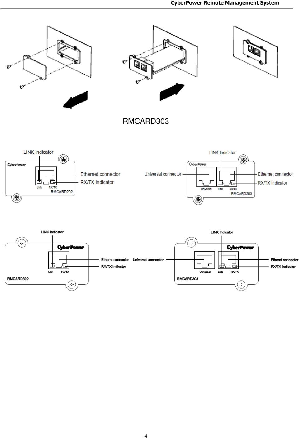
7 Definitions for LED Indicators Link LED color Off On (Yellow) Condition The Remote Management Card is not connected to the Network/or the Remote Management Card Power is off. The Remote Management Card is connected to the Network. TX/RX LED color Off On (Green) Flash The Remote Management Card power is off. The Remote Management Card power is on. - Receiving/transmitting data packet. - Reset finished. Step 2. Configure the IP address for the CyberPower Remote Management Card Method 1: Using the CyberPower Power Device Network Utility Tool 1. Install the CyberPower Power Device Network Utility Tool from the included CD. It is located in the \tools\network folder of the CD. Double click the Power Device Network Utility installation file, Setup.msi to begin the installation. 2. After installation completes, run the Power Device Network Utility program. Under All Programs, select CyberPower Power Device Network Utility. 3. The main dialog of the Power Device Network Utility Tool program is shown in Figure 1. The configuration tool will display all CyberPower Remote Management Cards of present on the same network. The "Refresh" button is used to search the entire local network for Remote Management Cards. Figure 1. The main window of the Power Device Network Utility program. 4. Select the Remote Management Card you are setting up. Click on the Tools menu and select Device Setup or double click the Remote Management Card you want to configure. 5. You can modify the IP Address, Subnet Mask, and Gateway address for the Device MAC Address listed in the Device Network Settings window, as shown in Figure 2. The default IP Address is and the default Subnet Mask is

 in the authentication window, as shown in figure 3.")
8 Figure 2. The setting window. 6. To modify the IP Address, Subnet Mask or Gateway address, enter the new addresses into the corresponding fields. 7. You will need to enter a User Name and Password for the Remote Management Card (Figure 3) in the authentication window, as shown in figure 3. *Default user name: cyber; Default password: cyber Figure 3. The authentication window. 8. If IP address is successfully set, you will see a message that the IP set up is OK, as shown in Figure 4.. Figure 4. Setup IP Address successfully message. 6

9 Method 2: Using a command prompt 1. Obtain the MAC address from the label on the Remote Management Card rear panel. Each Management card has a unique MAC address. 2. Use the ARP command to set the IP address. Example: To assign the IP Address for the Remote Management Card, which has a MAC address of 00-0C , you will type in the following command prompt from a PC connected to the same network as the Remote Management Card. A. Type in arp -s C then press Enter. 3. Use the Ping command to assign a size of 123 bytes to the IP. A. Type in ping l 123 then press Enter. B. If the replies are received, your computer can communicate with the IP address. To select an IP address for the Remote Management Card, please refer to Appendix 1. 7

10 WEB INTERFACE Login Account There are two types of user account: - Administrator (default username: cyber; default password: cyber) - Viewer (default username: device; default password: cyber) The Administrator can access and control all functions, including enable/disable of the Viewer account. The Viewer s access possesses read permissions for all functions but cannot control or change any settings. Note: 1. The Administrator account is also used for the FTP log in and authentication check in the Power Device Network Utility. 2. The Login process uses MD5 algorithm to protect the username and password. Web Content [Summary] Provide an overview of the system operation and the items that are auto refreshed; However, different model of RMCARD may have different items displayed. Item Current Condition Definition Display the current operating condition of UPS and environment sensor. UPS Status Battery Capacity Load Remaining Runtime The percentage of the current UPS battery capacity in a graph. The load of UPS as a percentage of available Watts in a graph. How long the UPS can support its load by battery power. System Data Name Location Contact Uptime The name of the equipment. The Location of the equipment. The person to contact about this equipment. How long the system has been working continuously. Envir Temperature The current temperature of the environment in a graph. 8

11 Humidity The current humidity of the environment in a graph. Envir Data Name Location Recent Device Events The name of the environment sensor. The location of the environment sensor. List the latest 5 events that occurred recently. [UPS] Following items can be displayed/configured through the UPS page; however, different UPS may have different items displayed/configured. [UPS->Status] Display the basic information about the current UPS status and the items are auto refreshed. Item Definition Input Status Voltage Frequency Display the present status of the utility power supplied to the UPS. The current input voltage of the utility power. The current frequency of the utility power supplied to the UPS. Output Status Voltage Frequency Load Non-Critical Bank Display the present status of the output power the UPS is supplying to connected equipment. The output voltage the UPS is supplying to the connected equipment. The output frequency the UPS is supplying to the connected equipment. The percentage of the total UPS capacity that is being supplied to the connected equipment. This is displayed as Watts in some UPS models. Display the present status of the NCL outlet. Battery Status Remaining Capacity Display the present status of the battery packs. The percentage of the current UPS battery capacity. 9
![[UPS->Status] Display the basic information about the current UPS status and the items are auto refreshed.](/docs-images/44/17543248/images/page_11.jpg "Item Definition Input Status Voltage Frequency Display the present status of the utility power supplied to the UPS. The current input voltage of the utility power.")
12 Remaining Runtime How long the UPS can support its load under battery mode. System Temperature The temperature inside the UPS. [UPS->Information] Provide the technical specifications of the connecting UPS. Information Model Name Voltage Rating Working Frequency Power Rating Current Rating Load Power Battery Voltage Rating Firmware Version USB Version LCD Version Battery Replacement Date Non-Critical Bank External Batteries Installation Place Description The model name of the UPS. The output voltage rating (Volts) of the UPS. The output frequency rating (Hz) of the UPS. The Volt-Amp rating of the UPS. The output current rating (Amps) of the UPS. The power rating (Watts) of the UPS. The DC voltage rating of the battery set. The version number of the UPS firmware. The version number of the UPS USB firmware The version number of the UPS LCD firmware The date that the batteries were last replaced This must be set manually and should be set after the batteries have been replaced or when the unit is first installed. If this date has not been set, it is recommended that this date should be set immediately. The amount of the Non-Critical Load. The amount of the external battery packs connected to the UPS. When clicking the Find it button, either the alarm will beep or the indicators will flash to inform users of the location. This helps users to identify a specific UPS in a multiple UPS installation. 10
 of the UPS. The output frequency rating (Hz) of the UPS.")
13 [UPS->Configuration] Configure the parameters of the UPS. Item Definition Supplied Power Voltage Set the output voltage which is supplied to the connected equipment. Utility Power Failure Condition High/Low Input (or Output) Voltage Threshold Frequency Tolerance When the utility power voltage or output voltage (according to the UPS support) is higher/lower than the threshold, the UPS will supply battery power to the connected equipment. This setting only comes into effect after a restart of the UPS. Sets the acceptable range of the input frequency. It will be in power failure condition if out of this tolerance. Operation Normal Generator Mode ECO Mode Manual Bypass Normal working mode of the UPS. If the UPS uses generator as its input power, this option should enable the UPS to function normally. If this option is selected, the UPS will be forbidden to enter Bypass mode or ECO mode to protect the powered equipment. On-line UPS enters Economy mode. The UPS will enter Bypass mode when the input voltage/frequency is in the range of thresholds. Once the utility voltage/frequency exceeds thresholds, the UPS will supply power to its load. Determine whether to allow the UPS to enter Manual Bypass mode. If this option is selected, the UPS will be forced to enter Bypass mode. Bypass Qualify Bypass No Bypass: If this option is selected, the UPS will not enter Bypass mode and will stop supplying output power. Check Volt/Freq: If the utility voltage is in range of the voltage thresholds and the utility frequency is in range of the frequency tolerance, the UPS will enter Bypass mode. 11

14 High/Low Bypass Voltage Power Restore Recharged Delay Recharged Capacity Returned Delay Otherwise the UPS will stop supplying output power. Check Volt Only: Only if the utility voltage is in the range of the voltage thresholds, the UPS will enter Bypass mode. Otherwise the UPS will stop supplying output power. When the UPS fault or overload occurs, the UPS will determine whether to enter Bypass mode according to the range of thresholds of utility voltage. If the utility voltage exceeds thresholds, the UPS will be forbidden to enter Bypass mode and stop supplying output power. After utility power is restored, the UPS turns on automatically and supplies power to the computer. If the computer BIOS is set to boot when power restores, the computer will restart automatically. The following settings are used to configure the UPS restore actions: When utility power is restored, the UPS will start to recharge after the specified delay is expired. When utility power is restored, the UPS will start to recharge after the specified battery capacity is met. When utility power is restored, the UPS will delay the restoration of output power. This option can be used to stagger the startup time of multiple UPSs to avoid overloading the utility power circuit or power source. The Returned Delay will take effect every time when the UPS restores power. This also includes the scheduling and user controlling task. Battery Low Battery Threshold External Battery Pack When the UPS supplies battery power and the remaining capacity is lower than this threshold, the UPS will alarm. Set the amount of external battery packs. This allows for an accurate runtime estimation based upon the total number of batteries. System Cold Start Set the ability of the UPS to start in the absence of input power. When this option is 12

15 Audible Alarm Dry Relay Function Screen Saver Time Wiring Fault Detect enabled, the UPS can be turned on without input power. If this option is enabled, the UPS will issue an audible alarm when supplying battery power or output overload. This configures the power condition for the UPS dry relay to function when the selected condition occurs. Refer to UPS manual for further information about advanced UPS dry relay utilization. The Dry Relay Function provides following power conditions: Utility Failure: The utility power fails and the UPS is using battery power. Low Battery: The battery capacity is too low to support the connected computers to shutdown. Alarm: The UPS is issuing the audible alarm due to the occurrence of warning events, such as overload. Bypass: The UPS has switched to Bypass mode due to overload or UPS fault. UPS Fault: The UPS could be malfunctioned due to hardware fault, such as inverter fault, bus fault or overheated. When no UPS button is pressed or no power event occurs during this delay, the LCD screen will be turned off. If this option is enabled, the UPS will detect if the UPS wiring is not grounded or is reversed. It is recommended to assure the UPS wiring has ground connection first. This option should be enabled if the UPS wiring has ground connection. Non-Critical Outlet Bank Turn Off Threshold Turn off Delay Time Turn On Delay Time When supplying battery power, the UPS will power off the NCL outlet if the remaining battery capacity is lower than this threshold. When supplying battery power, the UPS will power off this NCL outlet after this delay time is met. When utility power is restored, the UPS will restore the output of the NCL outlet after the delay time is met. This prevents excessive power consumption caused by all the connected equipment rebooting at the same time. 13

16 [UPS->Master Switch] Switch the output power of the UPS to be on or off. Item Reboot UPS Turn UPS Off UPS Sleep Cancel Switch Turn UPS On Shutdown/Sleep Delay Reboot Duration Signal Clients to Shutdown Definition Turn the UPS off and back on Turn the UPS off. This command is available under Utility Power Failure Mode. It will make UPS under sleep mode until power is restored. Cancel a pending action to turn the UPS off. Turn the UPS on. How long the UPS waits before it turns off in response to a "Reboot UPS", "Turn UPS off" or "UPS Sleep" command. After the UPS is turned off, Reboot Duration defines how long the UPS waits before it turns on in response to "Reboot UPS" command. Select this option to notify PowerPanel Business Edition Clients before UPS turning off. The Shutdown Delay for the UPS can be modified to ensure a graceful shutdown. [UPS->Bank Control] Display the current status of each Bank. Also, it provides on/off control for the Non-Critical Outlet Bank. Outlet Index and Device Name display the device that is powered by the specific bank. Item Non-Critical Outlet Index Device Name Definition Turn the non-critical bank on/off immediately. The index of outlet. Device Name on this outlet. [UPS->Diagnostics] When a power failure occurs, the UPS will supply battery power to all connected equipment immediately. The UPS must have sufficient runtime for all connected computers to be shut down properly. The UPS/Diagnostics page provides the information to verify if the UPS has sufficient battery runtime for the connected computers to shutdown properly. Perform a complete runtime calibration to ensure an accurate estimate of the runtime for the connected load. Battery Test The Battery Test will force the UPS to switch to battery power for 10 seconds. This allows the 14

17 user to verify the battery conditions and provides information about the battery, including the results and date of the last battery test. Click the Initiate button to begin a battery test. Performing a battery test is prohibited when the Frequency Working Mode option is set to fixed. If performing a battery test on the fixed frequency mode, a UPS fault may occur and cause the UPS to enter Bypass mode. The frequency on Bypass mode may not be accepted and may damage the connected equipment. The results will be reported after a battery test completes. Last Test Date: The date the last battery test was performed. Last Test Result: The results of the last battery test. Passed: The battery performs normally during the test. None: The UPS has never performed the battery test. Failed: The battery test results in failure. Follow the steps below if the battery test fails: Repeat the battery test and replace the batteries if the test fails again. Contact CyberPower for assistance if the battery test fails after the batteries have been replaced. Runtime Calibration The Runtime Calibration ensures the runtime estimate is accurate with the load and the current battery capacity. The results show the runtime, the results, and the date of the last calibration. When a runtime calibration is initiated, the connected equipment will be run on battery power until the batteries are completely discharged. Following the Runtime Calibration, the UPS will automatically begin recharging the batteries. Users can click the Start button to initiate a runtime calibration. Click the Cancel button to stop the runtime calibration. The result will be reported after a calibration is finished or canceled. Estimated Runtime: The estimated runtime of the batteries. Last Calibration Elapsed Time: The elapsed time of last Runtime calibration. Last Calibration Result: The results of the last runtime calibration. Passed: The runtime calibration is completed and the batteries are good. None: The UPS has never performed a runtime calibration. Failed: The UPS fails during the runtime calibration. Canceled: The calibration was interrupted. Last Calibration Date: The last date performing the runtime calibration. Note: 1. It is recommended to perform at least one calibration every 3 months. 2. A complete calibration causes the battery capacity to deplete. Ensure the UPS has recharged completely after performing a calibration. [UPS->Schedule]: Sets the UPS to automatically shutdown and restart at scheduled times (one time/per day/per week). The Schedule page manages scheduled shutdowns and lists all configured schedules. Each schedule row displays the details of when the schedule will take effect and when to perform it. 15

18 [One Time]: The user may set a specific date and time for the UPS shutdown. [Per Day]: Set a specific time of the day for the UPS shutdown. [Per Week]: Set a specific day and time of the week for the UPS shutdown. 1. Click [One Time], [Per Day] or [Per Week] option and Click Next>>, Enter the date and time to shut down the UPS. Select [Never], [Immediately], or the date and time for the UPS to restore power. Select the bank to be controlled, and click Shutdown Clients to set all clients to perform a graceful shutdown. You can enter a comment for this Schedule. 2. Click [Apply] to add the item to the Schedule. Click [Reset] to remove the item from the Schedule. 3. Applied settings are listed in [Schedule] menu. Note: The management system allows up to 10 scheduled settings. [UPS->Wake on Lan] This function is used to wake the PC through the network. (Make sure the PC hardware has such function supported and configures as "Enable" under BIOS). Enter the IP address of that PC when it is on and the system will search its MAC accordingly. The maximum number of IP that can be set is 50. [UPS->PowerPanel Clients] Display the Information of connected PPBE (PowerPanel Business Edition) Clients. The connection is executed by PPBE Clients and the listed clients will be removed if disconnected for 1 hour. [Envir] Following items can be displayed/configured through the Envir page (RMCARD 203/303 only). [Envir->Status] Display the basic information of the environment sensor and connected devices. Item Definition Information Name Location The name of the environment sensor. The location of the environment sensor. Temperature Current Value Maximum Minimum The current temperature of the environment. The highest temperature as well as the time of occurrence detected by the environment sensor. The lowest temperature as well as the time of occurrence detected by the environment sensor. Humidity Current Value The current humidity of the environment. 16
![Select [Never], [Immediately], or the date and time for the UPS to restore power. Select the bank to be controlled, and click Shutdown Clients to set all clients to perform a graceful shutdown.](/docs-images/44/17543248/images/page_18.jpg "You can enter a comment for this Schedule. 2. Click [Apply] to add the item to the Schedule. Click [Reset] to remove the item from the Schedule. 3. Applied settings are listed in [Schedule] menu.")
19 Maximum Minimum Contact The highest humidity as well as the time of occurrence detected by the environment sensor. The lowest humidity as well as the time of occurrence detected by the environment sensor. Display the name and status (Normal/Abnormal) of contacts. [Envir->Configuration] Item Definition Information Name Location The name used to identify the environment sensor. The place where the environment sensor is located. Temperature High Threshold Low Threshold Hysteresis Rate of Change Unit Upper limit for normal temperature. Lower limit for normal temperature. The difference between High/Low Threshold and the point where the temperature state is from abnormal to normal. The rate used to define abnormal change of temperature. The unit of temperature. Humidity High Threshold Low Threshold Hysteresis Rate of Change Upper limit for normal humidity. Lower limit for normal temperature. The difference between High/Low Threshold and the point where the humidity state is from abnormal to normal. The rate used to define abnormal change of humidity. Contact Name State The name used to identify the contact. The state used to define normal condition of the contact. 17
![[Envir->Configuration] Item Definition Information Name Location The name used to identify the environment sensor. The place where the environment sensor is located.](/docs-images/44/17543248/images/page_19.jpg "Temperature High Threshold Low Threshold Hysteresis Rate of Change Unit Upper limit for normal temperature. Lower limit for normal temperature.")
20 [Logs->Event Logs] Display the list of events and a brief description of each event along with the date and time stamp. Note: 1. The recordable events are listed under System->Notifications->Event Action. 2. The recorded time is using the 24-hour clock format. [Logs->Status Records] This page is used to view the logs of the UPS status and environment status; however, different product may have different items displayed. All items have the same definition as they are in the UPS status or environment status. Input min (V): The minimum input voltage of the utility power from the previous record. Input max (V): The maximum input voltage of the utility power from the previous record. Input (Hz): The current frequency of the utility power supplied to the UPS. Output (V): The output voltage of the UPS supplying to the connected equipment. Output (Hz): The output frequency of the UPS supplying to the connected equipment. Load (%): The percentage of the total UPS power load supplying to the connected equipment. Capacity (%): The percentage of the current UPS battery capacity. Remaining Runtime: How long the UPS can support its load under battery mode. Temperature: The current temperature of the environment. Humidity: The current humidity of the environment. [Logs->Graphing] This page is used to diagram the data of the Status Record. The graphing function makes the status records easier to be analysed. Item Graph Period Graph Data Graph Node Launch Graph in New Window Definition The period used to draw the graph backward from today. The longer period selected, the more graphing time is needed. The data used to draw the graph. The more data selected, the more graphing time is needed. Select Display All Nodes in Detail will display all the points along with the line; meanwhile, moving the cursor on the point will show the information of that point. If the box is not selected, the graph will show the line only but less graphing time is needed. Click the box will open a new page showing the graph in detail. [Logs->Maintenance] This page is used to maintain Event Logs and Status Records. The application provides information on how many events have been recorded before it is full. Item Definition 18
![[Logs->Status Records] This page is used to view the logs of the UPS status and environment status; however, different product may have different items displayed.](/docs-images/44/17543248/images/page_20.jpg "All items have the same definition as they are in the UPS status or environment status. Input min (V): The minimum input voltage of the utility power from the previous record.")
21 Event Logs Clear All The Number of Events Save Event Logs Clear the existing event logs. The number of existing event logs/the max number of event logs. Save the existing event logs as a txt file. Status Records Recording Interval Clear All Remaining Time Save Status Records Set the frequency to record the status data. A smaller interval will provide more frequent recordings but maintain them for a shorter period. A larger interval will provide less frequent recordings, but maintain them for a longer period. Clear the existing status records. The remaining recordable time base on the recording interval. Save the status records as a txt file. Note: Some old event logs/status records will be cleared automatically when there is no space to record. [System->General->User Account] This page is used to configure the login account. Information Administrator Viewer Manager IP Description The administrator can access full function, including enable/disable the Viewer account. The viewer can access the read function but can not control or change any settings. This IP setting is to set the allowable IP addresses. Users who log in as Admin (Viewer) can access RMCARD web pages if its IP Address is in one of Admin (Viewer) Manager IPs. If you want to access RMCARD from any IP address, you can set one of them as or Change Administrator account: Enter User Name Enter Current Password for Authentication Set the Manager IP (optional) Enter New Password Enter Confirm Password Click Apply 19
22 Change Viewer account: Select Allow Access to enable the Viewer account Enter the User Name Set the Manager IP (optional) Enter New Password Enter Confirm Password Click Apply [System->General->Date & Time]Current Settings: Displays the current date and time on the card and allows users to set the date and time. To set the date and time, users can choose to set manually or by using the NTP (Network Time Protocol) server. System Time Configuration: Choose the Time Zone off your location first, and Using NTP server: Enter the IP address/domain name of NTP servers, choose the time zone, and set the frequency to update the date and time from NTP server. Choose "Update right now" to update immediately. Manual Setup: Enter the date and time in the designated format. [System->General->Identification] Assign the system s name, contact, and location. Item Definition Name Contact Location The name of the equipment. Where the power equipment is located. The person to contact about this equipment. [System->General->Security] Set for security setting. Timeout Item Secret Phrase Definition The period (in minutes) that the system waits before auto logging off The Authentication Phrase used to communicate with PowerPanel Business Edition Client [System->Network Service->TCP/IPv4] Display the current TCP/IP settings: IP address, Subnet Mask, Gateway, and DNS server. This also provides the function to obtain TCP/IP settings from the DHCP server. - DHCP: Select the Enable DHCP option and click Apply to get IP address, Subnet Mask, and Gateway by DHCP. Select the Obtain DNS Address from DHCP option and click Apply to get the IP of DNS from the DHCP. - Manual : Enter the TCP/IP settings directly and click Apply. [System->Network Service->TCP/IPv6] Display the current the IPv6 settings. 20
23 - IPv6 Interface: Displays the current IPv6 address. - IPv6 Gateway: Displays the current IPv6 gateway. - IPv6 Configuration: - Allow Access: Set the IPv6 service to either Enable or Disable. - Router Control: The IPv6 address is assigned through the method (Stateless Address Autoconfiguration, Stateless DHCPv6 or Stateful DHCPv6) which is decided by router setting. - Manual: The IPv6 address is assigned by manuel setting. - Manual IPv6 Address : Enter the IPv6 address directly and click Apply when the Manuel box is checked. [System->Network Service->SNMPv1 Service] Allow users to select the NMS, defined by the IP settings that can use the channel to control the system data access through SNMPv1 Service. Item Allow Access Community Name IP Access Type Read Only Write/Read Forbidden Definition Set the SNMP service to either Enable or Disable. The name used to access this community by a Network Management System (NMS). The field must be 1 to 15 characters length. The IP address or IP address mask can be accessed by NMS. A specific IP address allows access only by the NMS with the specified IP Address. The 255 is regarded as the mask and the rules list as follows: : Access only by an NMS on the segment : Access only by an NMS on the 192 segment (the default setting) or : Access by any NMS on any segment. The allowable action for the NMS through the community and IP. Gets at anytime but cannot SETS. Gets at anytime, SETs anytime unless someone is logged in the Web interface. No GETS or SETS. [System->Network Service->SNMPv3 Service] Allow users to enable/disable SNMPv3 service and configure the parameters of accessing through SNMPv3 service (HW V2.0 above only). Allow Access Item Definition Set the SNMPv3 service to either Enable or Disable. 21
24 User Name Authentucation Password Privacy Password IP Authentucation Type Privacy Type The name to identify SNMPv3 user. The field must be 1 to 31 characters length. The password used to generate the key used for authentication. The field must be 16 to 31 characters length. The password used to generate the key used for encryption. The field must be 16 to 31 characters length. The IP address or IP address mask can be accessed by NMS. A specific IP address allows access only by the NMS with the specified IP Address. The 255 is regarded as the mask and the rules list as follows: : Access only by an NMS on the segment : Access only by an NMS on the 192 segment (the default setting) or : Access by any NMS on any segment. The hash type for authentication. The type for encrypting and decrypting data. [System->Network Service->Web Service] Select Enable to allow access to the HTTP or HTTPS(HW V2.0 above only) Service and configures the TCP/IP port for them. Use the Valid Certificate to browse the detailed information of HTTPS Certification;use the upload Certificate to upload and replace the HTTPS Certification. Note: The format of uploading certificate must in a standard PEM(Privacy Enhanced Mail). [System->Network Service->Telnet Service] Selects Enable to allow access to the Telnet Service and configures the TCP/IP port that Telnet uses to communicate (23 by default). Note: To enhance security, users can change port setting to any unused port from 5000 to Users must then specify the non-default port to obtain access. Telnet clients require users to append either a space and the port number or a colon and the port number to the command line to access the control console. [System->Network Service->FTP Service] Allows users to Enable/Disable the FTP server service and configure the TCP/IP port of the FTP server (21 by default). Note: The FTP server is used for upgrading Firmware. For more details about the upgrade process, please refer to Firmware Upgrade section. [System->Notifications->Event Action] Display the event actions for each event. Users can click on the event to modify its action. When a specific event happens, the user can be notified by the corresponding method according to this list. 22
25 - Log: Record the event in the Event Logs. - Send an to a specific user (An available SMTP server is necessary). - Trap: A SNMP trap sent to a specific IP address. - SMS: Send a short message to a specific mobile phone number (An available SMS service provider is needed). [System->Notifications->SMTP Server] After setting the proper SMTP server, the UPS can send an to users when a specific event occurs. Item Server's IP/Host Name Sender's Address Authentication Username Password Definition The IP or Host Name of SMTP server used to notify users by . The context of From field shown in the message sent to user. Select this option if the SMTP server needs Authentication check. Username used for Authentication. Password used for Authentication. [System->Notifications-> Recipients] Sets up to five recipients in designated address format. The Recipients will receive an notification when Events occur. To add a new recipient, click New Recipient. To modify or delete an existing Recipient, click the address of that recipient. To check if SMTP setting and the recipients are set correctly, click TEST button to check receiving status. [System->Notifications->Trap Receivers] List of NMS IP as TRAP receiver, and the number of receivers can be set up to 10. The receiver will receive a SNMP trap when an event occurs. To add a new receiver, click New Receiver. To modify or delete an existing receiver, click the IP address or name of that receiver. To check if the traps can be received correctly, click TEST button. [System->Notifications->SMS Service] Short Message Service (SMS) is a communication service used by mobile communication systems. Using standardized communication protocols will allow the interchange of short text messages between mobile devices. The system provides 4 methods to users to choose how they want to send the messages. Information Service provider is Clickatell Description Select the Clickatell option in the SMS Method field. Complete all the account details including Username, Password and HTTP API ID fields. 23
26 Service provider accepts HTTP GET Service provider accepts HTTP POST Service provider accepts (SMTP) This specification from the SMS provider is required before using the HTTP GET method. Select the Using HTTP GET option in the SMS Method field. Insert the E_PHONE_NUMBER as recipient's mobile phone number and the E_PHONE_MESSAGE as event message, describe in the specification, and fill in the URL field. The expressions will be replaced by relevant content before the Client sends a notification to SMS provider. This specification from the SMS provider is required before using the HTTP POST method to deliver messages to SMS providers. Select the Using HTTP POST option in the SMS Method field. Insert E_PHONE_NUMBER as recipient's mobile phone number and E_PHONE_MESSAGE as the event message, describe in the specification, and fill in the POST URL and POST BODY fields. The expressions will be replaced by the relevant content before the Agent/Client sends a notification to the SMS provider. This specification from a SMS provider is required before using the to deliver the messages to SMS providers. Select the Using option in the Service Provider field. Insert E_PHONE_NUMBER as recipient's mobile phone number and the E_PHONE_MESSAGE as event message, describe in the specification. Fill in the Recipient s Address, Subject and Content. The expressions will be replaced by the relevant content before the Agent/Client sends a notification to the SMS provider. [System->Notifications->SMS Recipients] Users can set up to 10 mobile phone numbers as SMS recipients. The Recipients will receive a short message notification when events occur. To add a new recipient, click New Recipient. To modify or delete an existing Recipient, click the mobile number or Name of that recipient. To test SMS settings, click TEST button and see if the test message is correctly received. 24
27 [System->About] Display vital information for the Remote Management Card. Item Model Name Firmware Version Firmware Updated Date Hardware Version MAC Address Save Configuration Restore Configuration Definition Model name of the Remote Management Card. The version number of the current firmware installed on Remote Management Card. The date the firmware was last updated. The hardware version of the Remote Management Card. MAC address of the Remote Management Card. Note: the MAC address is also listed on the top of the Remote Management Card. Click Save to save the configuration to local PC. The text file will have a default format of YYYY_MM_DD_HHMM.txt. Use this function to restore a configuration that has been saved earlier. Click Browse to the location of the saved configuration file and click Submit. 25
28 Reset to Default Setting / Recover from a Lost Password CyberPower Remote Management System To reset the CyberPower Remote Management Card to its default setting (including WEB log-in user name and password), please use the following steps RESET RMCARD202 RMCARD203 RESET RMCARD302 RMCARD Remove the two retaining screws on the card without turning off the UPS. 2. Uninstall the card. 3. Take off the jumper on the Reset pins as illustrated (the jumper is still necessary after reset, please do not lose or dispose it). 4. Re-install the card into the expansion port. 5. Wait until the Green LED is flashing (the frequency of the ON/OFF flashing is one second). 6. Uninstall the card again. 7. Place the jumper back onto the Reset pins. 8. Install card into the expansion port again. 9. Tighten the retaining screws. 26
29 Firmware Upgrade By upgrading the Firmware, you can obtain both the new features and updates/improvements to existing functionality. There are two files to update in order to upgrade the firmware version. RMCARD202/RMCARD203 upgrade files: (HW V2.0) - A. cpsrm2sbfw_xxx.bin - B. cpsrm2sbdata_xxx.bin (HW V1.0) - A. cpssnmpfw_xxx.bin - B. cpssnmpdata_xxx.bin RMCARD302/RMCARD303 upgrade files: (HW V2.0) - A. cpsrm3sbfw_xxx.bin - B. cpsrm3sbdata_xxx.bin (HW V1.0) - A. cpsrm302afw_xxx.bin - B. cpsrm302adata_xxx.bin Use the following steps to upgrade the firmware. 1. Download the latest Firmware 2. Extract the file to C:\ 3. Open a command prompt window 4. Login to the CyberPower Remote Management Card with FTP command, type - ftp - ftp> open - To [current ip of RMCARD] [port]; EX: To Input USER NAME and PASSWORD (same as the administrator account in Web interface default : cyber ; cyber) 5. Upgrade the file A, type ftp > bin ftp > put A (RMCARD202 for ex., put cpssnmpfw_xxx.bin) 6. Upgrade complete, type ftp > quit 7. The system will reboot after you type quit 8. Login to the FTP again as step Upgrade the file B, type ftp > bin ftp > put B (RMCARD202 for ex., put cpssnmpdata_xxx.bin) 10. Upgrade complete, type ftp > quit 11. The system will reboot after you type quit You can check to see if the firmware upgrade was successful by checking the Firmware version on the [System->About] webpage. Note: Please do not turn the UPS off when processing the Firmware upgrade. 27
30 Trouble Shooting Problem Unable to configure the Management Card by method 1 or method 2 in user s manual. Unable to ping the Management Card. Lost user name and password. Default Network Setting? Unable to access the Web Interface. Unable to operate a SNMP get/set. Unable to receive traps. Solution 1. Check the LED status, the normal condition is when yellow and green LED are both on. If green LED is off: => Check the Management Card for proper seating in the UPS and the UPS power is on. If yellow LED is off: => Ensure the network connection is valid 2. Ensure the PC being used is on the same physical network as Remote Management Card. 3. Ensure the Jumper on the Reset Pin is correctly installed. 1. Use method 1 and method 2 in user s manual to get/set a correct IP address for the Remote Management Card. 2. If the PC being used is on a different physical network from the Remote Management Card, verify the setting of subnet mask and the IP address of gateway. Please refer to the Reset to Default Setting / Recover from a Lost Password section of the user s manual. IP: Subnet mask : DHCP: On 1. Ensure the Http/Https access is enabled. 2. Ensure you can ping the RMCARD. 3. Ensure you are specifying the correct URL. SNMPv1: Verify the community name. SNMPv3: Verify the user profile configuration. 1. Ensure the trap types (SNMPv1/SNMPv3) and trap receiver are configured correctly. 2. Ensure the IP address of gateway is configured correctly if the RMCARD and NMS is on a different physical network. 28
31 Appendix 1. IP Address Settings for CyberPower Remote Management Card Overview All devices on a computer network need to have an IP address. Each device s IP address is unique. The same address cannot be used twice. In order to assign an IP address to the CyberPower Remote Management Card, you must determine the range of the available IP addresses, and then choose an unused IP address to assign to the Remote Management Card. PLEASE NOTE: You may need to contact your network administrator to obtain an available IP address. Procedures to find an IP address: 1. Locate the subnet of CyberPower Remote Management Card. One way to determine the range of possible IP addresses is to view the network configuration on a workstation. Click on [Start] and select [Run]. Type command into the open box and click [OK]. At the command prompt type ipconfig /all and press [Enter]. The computer will display network information as listed below: Ethernet adapter Connection-specific DNS Suffix : xxxx.com Description : D-Link DE220 ISA PnP LAN adapter Physical Address.: C8-DA-7A-C0 DHCP Enabled...: Yes Autoconfiguration Enabled...: Yes IP Address..: Subnet Mask..: Default Gateway.....: DHCP Server...: DNS Servers : Select an IP Address for CyberPower Remote Management Card Verify the IP Addresses for the computer and the Remote Management Card belong to the same subnet. Refer to the above network information, the possible IP Address for the Remote Management Card could be * (* hereafter represents any number between 1 and 255). Similarly, if the Subnet Mask is , the IP Address for Remote Management Card could be set up as *.* to reach the same subnet with the computer. To verify there is no other equipment connected to the network using the same IP Address, run Ping at the DOS Mode prompt when the IP Address you would like to set is If the response is presented as below, the IP address is most likely not used and may be available for the CyberPower Remote Management Card. Pinging with 32 bytes of data: Request timed out. Request timed out. Request timed out. Request timed out. 29
32 If the response is shown as below, the IP address is in use. Try another IP address until an available address is found. Pinging with 32 bytes of data: Reply from : bytes=32 time<10ms TTL=64 Reply from : bytes=32 time<10ms TTL=64 Reply from : bytes=32 time<10ms TTL=64 Reply from : bytes=32 time<10ms TTL=64 30
33 CyberPower Systems (USA), Inc th Avenue East, Suite 400, Shakopee, MN Phone: (952) Toll-free: (877) Website: CyberPower Systems, Inc. Website: 31
User s Manual Network Management Card
 User s Manual Network Management Card RMCARD202 Intelligent Network Management Card allows a UPS system to be managed, monitored, and configured Version 1.0 E-K01-SNMP005-0 TABLE OF CONTENTS Introduction
User s Manual. Remote Management Card RMCARD202. Intelligent Remote Management Card allows a UPS system to be managed, monitored, and configured
 User s Manual Remote Management Card RMCARD202 Intelligent Remote Management Card allows a UPS system to be managed, monitored, and configured Version 1.2 TABLE OF CONTENTS Introduction 1 Installation
Remote Management Card
 Remote Management Card RMCARD202 / RMCARD203 RMCARD302 / RMCARD303 User s Manual Version 2.0 The Remote Management Card allows a UPS system and environmental sensor to be managed, monitored, and configured.
User s Manual UPS SERIES. Network Interface Card UPS-IPCARD. I-00453 Rev B
 User s Manual UPS SERIES Network Interface Card UPS-IPCARD I-00453 Rev B TABLE OF CONTENTS INTRODUCTION............................................................. 3-4 INSTALLATION GUIDE.......................................................
SNMP Web card. User s Manual. Management Software for Uninterruptible Power Supply Systems
 SNMP Web card User s Manual Management Software for Uninterruptible Power Supply Systems Table of Contents 1. Overview... 3 1.1 Introduction... 3 1.2 Features... 3 1.3 Overlook... 3 1.4 Installation and
Network Management Card. User Manual
 User Manual 1 Contents Contents 2 Chapter 1 Overview 3 1.1 NMC package contents 4 1.2 NMC CD Resources 4 1.3 Features 4 1.4 NMC Applications 5 Chapter 2 NMC parameters setting via serial COM port 6 2.1
User s Manual PowerPanel Shutdown Service Graceful Shutdown and Notification service to ensure power protection of your computer
 User s Manual PowerPanel Shutdown Service Graceful Shutdown and Notification service to ensure power protection of your computer Revision 1.1 TABLE OF CONTENTS INTRODUCTION... 1 INSTALLATION GUIDE... 2
User s Manual Remote Management Card
 User s Manual Remote Management Card RMCARD202TAA/RMCARD203TAA RMCARD302TAA/RMCARD303TAA The Remote Management Card allows a UPS system and environmental sensor to be managed, monitored, and configured
PowerPanel Business Edition USER MANUAL
 USER MANUAL Rev. 0.9 2007/10/26 Copyright 2006-2007 Cyber Power Systems, Inc. All rights reserved. PowerPanel Business Edition USER S MANUAL PowerPanel Business Edition provides power management Services.
3.5 EXTERNAL NETWORK HDD. User s Manual
 3.5 EXTERNAL NETWORK HDD User s Manual Table of Content Before You Use Key Features H/W Installation Illustration of Product LED Definition NETWORK HDD Assembly Setup the Network HDD Home Disk Utility
SNMP Web Management. User s Manual For SNMP Web Card/Box
 SNMP Web Management User s Manual For SNMP Web Card/Box Management Software for Off-Grid Inverter Version: 1.2 Table of Contents 1. Overview... 1 1.1 Introduction... 1 1.2 Features... 1 1.3 Overlook...
NetProbe Lite. Web Based 8 Channel Sensor Collector. User Manual. Version 1.2
 NetProbe Lite Web Based 8 Channel Sensor Collector User Manual Version 1.2 Copyright Information Copyright 2004-2005, Mega System Technologies, Inc. All rights reserved. Reproduction without permission
Quick Installation Guide Network Management Card
 Rev.1.1 www.cyberpowersystems.com Quick Installation Guide Network Management Card Intelligent Network Management Card allows UPS to be managed, monitored, and configured via SNMP Card Configuration Tool
ViewPower. User s Manual. Management Software for Uninterruptible Power Supply Systems
 ViewPower User s Manual Management Software for Uninterruptible Power Supply Systems Table of Contents 1. ViewPower Overview... 2 1.1. Introduction...2 1.2. Structure...2 1.3. Applications...2 1.4. Features...2
Chapter 6 Using Network Monitoring Tools
 Chapter 6 Using Network Monitoring Tools This chapter describes how to use the maintenance features of your Wireless-G Router Model WGR614v9. You can access these features by selecting the items under
ViewPower Pro. User s Manual. Management Software for Uninterruptible Power Supply Systems
 ViewPower Pro User s Manual Management Software for Uninterruptible Power Supply Systems Table of Contents 1. ViewPower Pro Overview...4 1.1. Introduction...4 1.2. Structure...4 1.3. Features...5 2. ViewPower
TDP43ME NetPS. Network Printer Server. Control Center. for Ethernet Module
 Panduit Corp. 2010 TDP43ME NetPS PA26306A01 Rev. 01 11-2010 Network Printer Server Control Center for Ethernet Module NOTE: In the interest of higher quality and value, Panduit products are continually
Title Page Web/SNMP Management SmartSlot Card
 Title Page Web/SNMP Management SmartSlot Card AP9606 User s Guide Thank You! Thank you for selecting the APC Web/SNMP Management SmartSlot Card. It has been designed for many years of reliable, maintenance-free
Dell Network Management Card. User's Guide. w w w. d e l l. c o m s u p p o r t. d e l l. c o m
 Dell Network Management Card User's Guide w w w. d e l l. c o m s u p p o r t. d e l l. c o m Notes and Warnings NOTE: A NOTE indicates important information that helps you make better use of your software.
IP Power Stone 4000 User Manual
 IP Power Stone 4000 User Manual Two Outlet Remote AC Power Controller Multi Link, Inc. 122 Dewey Drive Nicholasville, KY 40356 USA Sales and Tech Support 800.535.4651 FAX 859.885.6619 techsupport@multi
Gigabyte Management Console User s Guide (For ASPEED AST 2400 Chipset)
") Gigabyte Management Console User s Guide (For ASPEED AST 2400 Chipset) Version: 1.4 Table of Contents Using Your Gigabyte Management Console... 3 Gigabyte Management Console Key Features and Functions...
Gigabyte Management Console User s Guide (For ASPEED AST 2400 Chipset) Version: 1.4 Table of Contents Using Your Gigabyte Management Console... 3 Gigabyte Management Console Key Features and Functions...
c. Securely insert the Ethernet cable from your cable or DSL modem into the Internet port (B) on the WGT634U. Broadband modem
 on the WGT634U. Broadband modem") Start Here Follow these instructions to set up your router. Verify That Basic Requirements Are Met Assure that the following requirements are met: You have your broadband Internet service settings handy.
Start Here Follow these instructions to set up your router. Verify That Basic Requirements Are Met Assure that the following requirements are met: You have your broadband Internet service settings handy.
Ultra Thin Client TC-401 TC-402. Users s Guide
 Ultra Thin Client TC-401 TC-402 Users s Guide CONTENT 1. OVERVIEW... 3 1.1 HARDWARE SPECIFICATION... 3 1.2 SOFTWARE OVERVIEW... 4 1.3 HARDWARE OVERVIEW...5 1.4 NETWORK CONNECTION... 7 2. INSTALLING THE
Starting Guide - Poseidon 3265 First steps for remote monitoring with Poseidon & GSM
 Poseidon 3265 starting guide Poseidon 3265 Starting Guide - Poseidon 3265 First steps for remote monitoring with Poseidon & GSM 1) Connecting Poseidon 3265 1.1) Check DIP switches settings. For installation
Gigabyte Content Management System Console User s Guide. Version: 0.1
 Gigabyte Content Management System Console User s Guide Version: 0.1 Table of Contents Using Your Gigabyte Content Management System Console... 2 Gigabyte Content Management System Key Features and Functions...
ViewPower Pro. User s Manual. Management Software for Uninterruptible Power Supply Systems
 ViewPower Pro User s Manual Management Software for Uninterruptible Power Supply Systems Table of Contents 1. ViewPower Pro Overview...3 1.1. Introduction...3 1.2. Structure...3 1.3. Features...4 2. ViewPower
Chapter 6 Using Network Monitoring Tools
 Chapter 6 Using Network Monitoring Tools This chapter describes how to use the maintenance features of your RangeMax Wireless-N Gigabit Router WNR3500. You can access these features by selecting the items
Manual. IP Sensor and Watchdog IPSW2210. I P S W 2 2 1 0 M a n u a l P a g e 1. Relay Output. Power input. 12VDC adapter LED Indicators. 2 Dry.
 IP Sensor and Watchdog IPSW2210 Manual Relay Output Power input 12VDC adapter LED Indicators 1 wire 2 Dry Output Green : Power Yellow: Link temperature & humidity contact inputs LED indicator sensor input
External Storage 200 Series. User s Manual
 External Storage 200 Series User s Manual Version 1.2 00P3DS200ZSEA2 Table of Contents User s Manual 1. Overview...3 2. Key Features...3 3. Rear Connectors...4 4. Setup the External Storage 200...4 5.
Installation and Configuration User's Guide
 Dell UPS Management Software Installation and Configuration User's Guide www.kesintisizservis.com Notes NOTE: A NOTE indicates important information that helps you make better use of your software. Information
Table of Contents. 1. Introduction...1. 2. PDU Package...2. 3. Function...3. 4. Installation...5. 5. Web Interface...7
 PDU User Manual Table of Contents 1. Introduction...1 2. PDU Package...2 3. Function...3 4. Installation...5 5. Web Interface...7 1. Introduction The PDU is an Internet ready device designed and is equipped
SentryPlus. Shutdown Management Software for Windows. User s Manual
 SentryPlus Shutdown Management Software for Windows User s Manual Table of Contents Introduction...3 SentryPlus Features...3 SentryPlus Installation...4 SentryPlus Setup...4 SentryPlus Service...5 SentryPlus
SNMP-SSL UPS SNMP Card (Web-Based monitoring SNMP Card) User s Manual
 User s Manual") UPS SNMP Card (Web-Based monitoring SNMP Card) User s Manual Table of Contents Electronic Emission Notice... 3 Safety Information... 3 Chapter 1 Introduction... 4 Features...4 Package Contents... 5 System
UPS SNMP Card (Web-Based monitoring SNMP Card) User s Manual Table of Contents Electronic Emission Notice... 3 Safety Information... 3 Chapter 1 Introduction... 4 Features...4 Package Contents... 5 System
Broadband Router ESG-103. User s Guide
 Broadband Router ESG-103 User s Guide FCC Warning This equipment has been tested and found to comply with the limits for Class A & Class B digital device, pursuant to Part 15 of the FCC rules. These limits
3.5 Mobile LAN Disk. User Guide
 3.5 Mobile LAN Disk User Guide Contents 1. Hardware...2 1.1 Power...2 1.2 Ports...2 1.3 Reset Button...2 1.4 LEDs...2 1.5 Front View...3 1.6 Rear View...3 2. Installation....... 4 2.1 Requirements 4 2.2
Network Power Manager. User Manual
 Network Power Manager User Manual Table of Contents 1. Introduction... 1 2. PDU Package... 2 3. Function... 3 4. Installation... 4 5. Web Interface... 5 1. Introduction The PDU is an Internet ready device
User Manual WatchPower
 User Manual WatchPower Management Software for Inverter Table of Contents 1. WatchPower Overview... 1 1.1. Introduction... 1 1.2. Features... 1 2. WatchPower Install and Uninstall... 1 2.1. System Requirement...
USER S GUIDE Switched Rack PDU
 Contents Introduction--1 Product Description....................................... 1 Access Procedures....................................... 3 Recover From a Lost Password..............................
How To Check If Your Router Is Working Properly On A Nr854T Router (Wnr854) On A Pc Or Mac) On Your Computer Or Ipad (Netbook) On An Ipad Or Ipa (Networking
 On A Pc Or Mac) On Your Computer Or Ipad (Netbook) On An Ipad Or Ipa (Networking") Chapter 7 Using Network Monitoring Tools This chapter describes how to use the maintenance features of your RangeMax NEXT Wireless Router WNR854T. These features can be found by clicking on the Maintenance
Chapter 7 Using Network Monitoring Tools This chapter describes how to use the maintenance features of your RangeMax NEXT Wireless Router WNR854T. These features can be found by clicking on the Maintenance
User s Manual. Management Software for Inverter
 WatchPower User s Manual Management Software for Inverter Table of Contents 1. WatchPower Overview... 2 1.1. Introduction... 2 1.2. Features... 2 2. WatchPower Install and Uninstall... 2 2.1. System Requirement...
Product Description... 1 Internal Management Features... 3 Front Panel... 5 Watchdog Features... 7
 Contents Introduction--1 Product Description.................................. 1 Internal Management Features........................... 3 Front Panel........................................ 5 Watchdog
PowerPanel Business Edition User s Manual
 PowerPanel Business Edition User s Manual Rev. 20 2015/08/18 ELECTRONIC END USER LICENSE AGREEMENT FOR CYBERPOWER POWERPANEL BUSINESS EDITION NOTICE TO USER: THIS IS A CONTRACT. BY INSTALLING THIS SOFTWARE
How To Check If Your Router Is Working Properly
 Chapter 6 Using Network Monitoring Tools This chapter describes how to use the maintenance features of your RangeMax Dual Band Wireless-N Router WNDR3300. You can access these features by selecting the
Configuration Manual English version
 Configuration Manual English version Frama F-Link Configuration Manual (EN) All rights reserved. Frama Group. The right to make changes in this Installation Guide is reserved. Frama Ltd also reserves the
SNMP-NET UPS SNMP Card (Web-Based monitoring SNMP Card)
") UPS SNMP Card (Web-Based monitoring SNMP Card) User s Manual PN: 34000281 R1 Table of Contents Chapter 1 Introduction...3 Features...3 System Application...3 Chapter 2 Installation...4 SNMP-NET Chapter
UPS SNMP Card (Web-Based monitoring SNMP Card) User s Manual PN: 34000281 R1 Table of Contents Chapter 1 Introduction...3 Features...3 System Application...3 Chapter 2 Installation...4 SNMP-NET Chapter
Users manual. TCW181B-CM_R1 Page 1
 Ethernet controller TCW181B-CM Users manual 1. Short description TCW181B-CM is 8-channel Ethernet relay board, which is designed to work in IP-based networks and managed by WEB interface or SNMP programs.
PowerPanel Business Edition User s Manual
 PowerPanel Business Edition User s Manual Rev. 19 2015/06/30 ELECTRONIC END USER LICENSE AGREEMENT FOR CYBERPOWER POWERPANEL BUSINESS EDITION NOTICE TO USER: THIS IS A CONTRACT. BY INSTALLING THIS SOFTWARE
PREFACE http://www.okiprintingsolutions.com 07108001 iss.01 -
 Network Guide PREFACE Every effort has been made to ensure that the information in this document is complete, accurate, and up-to-date. The manufacturer assumes no responsibility for the results of errors
Chapter 4 Management. Viewing the Activity Log
 Chapter 4 Management This chapter describes how to use the management features of your NETGEAR WG102 ProSafe 802.11g Wireless Access Point. To get to these features, connect to the WG102 as described in
Chapter 3 Management. Remote Management
 Chapter 3 Management This chapter describes how to use the management features of your ProSafe 802.11a/g Dual Band Wireless Access Point WAG102. To access these features, connect to the WAG102 as described
Environmental Monitoring Unit
 Environmental Monitoring Unit AP9312TH AP9312THi User s Guide Contents Environmental Monitoring Unit Managing the Unit............................ 1 Introduction.................................. 1 Available
Management Software. Web Browser User s Guide AT-S106. For the AT-GS950/48 Gigabit Ethernet Smart Switch. Version 1.0.0. 613-001339 Rev.
 Management Software AT-S106 Web Browser User s Guide For the AT-GS950/48 Gigabit Ethernet Smart Switch Version 1.0.0 613-001339 Rev. A Copyright 2010 Allied Telesis, Inc. All rights reserved. No part of
Power Supply SNMP Interface User Manual for SRL versions
 Power Supply SNMP Interface User Manual for SRL versions SNMP-L User Manual 150722(firmware 02r_a12).doc Table of Contents 1. INTRODUCTION... 3 1.1 Default IP Address... 3 2. LOGIN... 4 3. MONITORING &
Sentry Bulldog Shutdown Management Software (For UNIX Series)
") Sentry Bulldog Shutdown Management Software (For UNIX Series) User Manual Table of Contents Introduction...4 Sentry Bulldog Installation...5 Sentry Bulldog Services...6 Sentry Bulldog Monitor...7 Networking...8
Sentry Bulldog Shutdown Management Software (For UNIX Series) User Manual Table of Contents Introduction...4 Sentry Bulldog Installation...5 Sentry Bulldog Services...6 Sentry Bulldog Monitor...7 Networking...8
How to Log On... 15 Main Screen... 18 Control Console Menus... 21. How to Log On... 24 Summary Page... 27 Navigation Menu... 29
 Contents Introduction--1 Product Description.................................. 1 Access Procedures.................................... 3 How to Recover From a Lost Password..................... 6 Upgrading
your Gateway Windows network installationguide 802.11b wireless series Router model WBR-100 Configuring Installing
 your Gateway Windows network installationguide 802.11b wireless series Router model WBR-100 Installing Configuring Contents 1 Introduction...................................................... 1 Features...........................................................
Wireless Router Setup Manual
 Wireless Router Setup Manual NETGEAR, Inc. 4500 Great America Parkway Santa Clara, CA 95054 USA 208-10082-02 2006-04 2006 by NETGEAR, Inc. All rights reserved. Trademarks NETGEAR is a trademark of Netgear,
ViewPower User Manual
 ViewPower User Manual Management Software for Uninterruptible Power Supply Systems Table of Contents 1. ViewPower Overview... 1 1.1. Introduction... 1 1.2. Structure... 1 1.3. Applications... 1 1.4. Features...
This section will focus on basic operation of the interface including pan/tilt, video, audio, etc.
 Catalogue Basic Operation... 2 For Internet Explorer... 2 For Other Non-IE Web Browsers... 5 Camera Settings... 6 System... 6 About... 6 PT Setting... 7 Backup and Restore Setup... 8 NTP Setting... 8 System
Internet Telephony PBX system IPX-1980
 Internet Telephony PBX system IPX-1980 Quick Installation Guide Table of Contents 1. Package Contents... 3 2. Hardware Installation... 4 2.1 Safety Instruction... 4 2.2 Front panel... 4 2.3 LED & Button
PowerPanel Business Edition Installation Guide
 PowerPanel Business Edition Installation Guide For Automatic Transfer Switch Rev. 5 2015/12/2 Table of Contents Introduction... 3 Hardware Installation... 3 Install PowerPanel Business Edition Software...
Innovative Electronics for a Changing World INDEX
 Innovative Electronics for a Changing World INDEX 1. SYSTEM DESCRIPTION 2. BOARD CONNECTIONS terminals and indicators 3. CONNECTION DIAGRAM 4. START UP GUIDE and passwords 5. HOME PAGE 6. STATUS PAGE 7.
N300 WiFi Range Extender
 Model EX2700 User Manual July 2014 202-11395-01 350 East Plumeria Drive San Jose, CA 95134 USA Support Thank you for selecting NETGEAR products. After installing your device, locate the serial number on
Embedded Web Server. User Guide. General usage guide lines to the ISONAS Embedded Web Server available on all ISONAS PowerNet reader-controllers
 Embedded Web Server User Guide General usage guide lines to the ISONAS Embedded Web Server available on all ISONAS PowerNet reader-controllers 06/12/09 Contents Revision history... 4 Scope... 4 Introduction...
Network Management Card
 Network Management Card Installation manual IP= MAC=00E0D8FF855E Reset 100 10 data Card Settings 1 2 RS232 Download ETHERNET RS232 66074 34003641EN/AG - Page 1 1 2 1 2 Quick start ASI or STS U-Talk ASI
3.1 RS-232/422/485 Pinout:PORT1-4(RJ-45) RJ-45 RS-232 RS-422 RS-485 PIN1 TXD PIN2 RXD PIN3 GND PIN4 PIN5 T+ 485+ PIN6 T- 485- PIN7 R+ PIN8 R-
 RJ-45 RS-232 RS-422 RS-485 PIN1 TXD PIN2 RXD PIN3 GND PIN4 PIN5 T+ 485+ PIN6 T- 485- PIN7 R+ PIN8 R-") MODEL ATC-2004 TCP/IP TO RS-232/422/485 CONVERTER User s Manual 1.1 Introduction The ATC-2004 is a 4 Port RS232/RS485 to TCP/IP converter integrated with a robust system and network management features
MODEL ATC-2004 TCP/IP TO RS-232/422/485 CONVERTER User s Manual 1.1 Introduction The ATC-2004 is a 4 Port RS232/RS485 to TCP/IP converter integrated with a robust system and network management features
User Manual. Onsight Management Suite Version 5.1. Another Innovation by Librestream
 User Manual Onsight Management Suite Version 5.1 Another Innovation by Librestream Doc #: 400075-06 May 2012 Information in this document is subject to change without notice. Reproduction in any manner
User s Manual. Management Software for ATS
 ATS Monitor User s Manual Management Software for ATS Table of Contents 1. ATS Monitor Overview... 2 2. ATS Monitor Install and Uninstall... 2 2.1. System Requirement... 2 2.2. Software Install... 2 2.3.
Wifi Pan/Tilt IP Camera User Manual
 Wifi Pan/Tilt IP Camera User Manual Rev. 3.0 Software Version 3.00 May. 25 th.2009 Table of Contents 1. PRODUCT VIEWS...3 1.1. PRONT PANEL...3 1.2. BACK PANEL...3 1.3. ACCESSORIES...4 2. SETUP AND STARTUP...5
PLANET is a registered trademark of PLANET Technology Corp. All other trademarks belong to their respective owners.
 Trademarks Copyright PLANET Technology Corp. 2004 Contents subject to revise without prior notice. PLANET is a registered trademark of PLANET Technology Corp. All other trademarks belong to their respective
PN5212/PN5320/PN7212/PN7320
 PN522/PN5/PN722/PN7 Over the NET Distribution Units ALTUSEN Over the NET products are Distribution Units that offer outlet level control combined with remote access to give IT administrators the ability
NetAgent. UPS SNMP Agent. User s Manual
 NetAgent UPS SNMP Agent User s Manual User Guide for the NetAgent Version 3.30 Firmware version 2.35 Copyright Information Copyright 2000-2004, Mega System Technologies, Inc. All rights reserved. Reproduction
Control Software for UPS with LAN-Ethernet Interface
 ENGLISH Control Software for UPS with LAN-Ethernet Interface User s Manual Management Software for Uninterruptible Power Supply Systems VPP 1.13 User manual Page 1 1. View Power Overview 4 1.1. Introduction
User s Manual. Management Software for Uninterruptible Power Supply Systems
 PowerShield NetGuard User s Manual Management Software for Uninterruptible Power Supply Systems Table of Contents 1. NetGuard Overview...2 1.1. Introduction...2 1.2. Structure...2 1.3. Applications...3
AXIS 205 Network Camera Goes anywhere your network goes
 I N S T A L L A T I O N G U I D E Goes anywhere your network goes Introduction 1 Introduction Focus guide (see page 6) Status indicator (surrounding the focus ring) Focus ring (see page 6) Serial number
HWg-STE HWg-STE PoE MANUAL
 HWg-STE HWg-STE PoE MANUAL www.hw-group.com Page 2 HWg-STE connectors LED indicators Green: Power & Mode Yellow: Link & Activity SENSORS S1 and S2 ports for connecting temperature or humidity sensors.
IP SENSOR 9216 USER MANUAL IP SENSOR 9216 USER MANUAL
 IP SENSOR 9216 USER MANUAL USER MANUAL IP SENSOR 9216 Version: 1.0 2006.08-1 - VER. 1.0, Warning: Any changes to this equipment without permission may cause damages to your equipment! This equipment has
Olson Electronics Remote Power Monitoring Meter
 Olson Electronics Remote Power Monitoring Meter Operation Guide Key Features Amps: 00.00 to 32.00A True RMS (rated short period to 40A) Volts: 200.0 to 250.0V True RMS Watts: 0000 to 9999W KWh: 000000.0
Chapter 1 Configuring Internet Connectivity
 Chapter 1 Configuring Internet Connectivity This chapter describes the settings for your Internet connection and your wireless local area network (LAN) connection. When you perform the initial configuration
DVG-2101SP VoIP Telephone Adapter
 This product can be set up using any current web browser, i.e., Internet Explorer 6 or Netscape Navigator 6.2.3. DVG-2101SP VoIP Telephone Adapter Before You Begin 1. If you purchased this VoIP Telephone
SIP Proxy Server. Administrator Installation and Configuration Guide. V2.31b. 09SIPXM.SY2.31b.EN3
 SIP Proxy Server Administrator Installation and Configuration Guide V2.31b 09SIPXM.SY2.31b.EN3 DSG, DSG logo, InterPBX, InterServer, Blaze Series, VG5000, VG7000, IP590, IP580, IP500, IP510, InterConsole,
How To Use 1Bay 1Bay From Awn.Net On A Pc Or Mac Or Ipad (For Pc Or Ipa) With A Network Box (For Mac) With An Ipad Or Ipod (For Ipad) With The
 With A Network Box (For Mac) With An Ipad Or Ipod (For Ipad) With The") 1-bay NAS User Guide INDEX Index... 1 Log in... 2 Basic - Quick Setup... 3 Wizard... 3 Add User... 6 Add Group... 7 Add Share... 9 Control Panel... 11 Control Panel - User and groups... 12 Group Management...
1-bay NAS User Guide INDEX Index... 1 Log in... 2 Basic - Quick Setup... 3 Wizard... 3 Add User... 6 Add Group... 7 Add Share... 9 Control Panel... 11 Control Panel - User and groups... 12 Group Management...
6.0. Getting Started Guide
 6.0 Getting Started Guide Netmon Getting Started Guide 2 Contents Contents... 2 Appliance Installation... 3 IP Address Assignment (Optional)... 3 Logging In For the First Time... 5 Initial Setup... 6 License
USER MANUAL GUIMGR Graphical User Interface Manager for FRM301/FRM401 Media Racks
 USER MANUAL GUIMGR Graphical User Interface Manager for FRM301/FRM401 Media Racks CTC Union Technologies Co., Ltd. Far Eastern Vienna Technology Center (Neihu Technology Park) 8F, No. 60 Zhouzi St. Neihu,
Networking. General networking. Networking overview. Common home network configurations. Wired network example. Wireless network examples
 Networking General networking Networking overview A network is a collection of devices such as computers, printers, Ethernet hubs, wireless access points, and routers connected together for communication
GW400 VoIP Gateway. User s Guide
 GW400 VoIP Gateway User s Guide P/N: 956YD30001 Copyright 2006. All Rights Reserved. Document Version: 1.0 All trademarks and trade names are the properties of their respective owners. i Table of Contents
Movie Cube. User s Guide to Wireless Function
 Movie Cube User s Guide to Wireless Function Table of Contents 1. WLAN USB Adapter Connection...3 2. Wireless Setup...4 2.1 Infrastructure (AP)...5 2.2 Peer to Peer (Ad Hoc)...7 2.3 Settings for PC...8
HP ProLiant ML150 System Monitor User Guide
 HP ProLiant ML150 System Monitor User Guide November 2003 Contents Introduction... 1 MSM Features...1 Installing MSM... 3 Installing MSM Server on the Server...3 Installing MSM Console on a Client PC...3
Welcome. Unleash Your Phone
 User Manual Welcome Unleash Your Phone For assistance with installation or troubleshooting common problems, please refer to this User Manual or Quick Installation Guide. Please visit www.vonage.com/vta
8/16-Port IP KVM Switch IKVM-8010 / IKVM-16010. Quick Installation Guide
 8/16-Port IP KVM Switch IKVM-8010 / IKVM-16010 Quick Installation Guide Table Of Contents Chapter 1 Introduction... 3 1.1 Features... 3 1.2 Package Contents... 4 1.3 Technical Specifications... 4 Chapter
SNMP Manager User s Manual
 SNMP Manager User s Manual Table of Contents 1. Introduction...2 2. SNMP Manager Install, Quick Start and Uninstall...2 2.1. Software Installation...2 2.2. Software Quick Start...2 2.3. Software Uninstall...2
MasterSwitch Power Distribution Unit
 MasterSwitch Power Distribution Unit AP9211 AP9212 AP9217 AP9218 User s Guide Contents MasterSwitch Power Distribution Unit Introduction................................. 1 Product Description.............................
Addonics T E C H N O L O G I E S. NAS Adapter. Model: NASU2. 1.0 Key Features
 1.0 Key Features Addonics T E C H N O L O G I E S NAS Adapter Model: NASU2 User Manual Convert any USB 2.0 / 1.1 mass storage device into a Network Attached Storage device Great for adding Addonics Storage
4. Rear View. Function Switches 1. Fixed IP 2. DHCP Floating IP 3. Auto IRIS (DC Driver LENS) 4. Fixed LENS (AES)
 4. Fixed LENS (AES)") 4. Rear View 5 1.STATIC IP 2.DHCP 3.DC IRIS Mini USB 1 2 3 4 5 6 1. ALM-RST 2. ALM-IN 3. ALM-OUT 4. GND 5. RS485-6. RS485 + 1 2 3 4 5 6 7 DC Power Input: DC Jackψ2.1, DC12V---0.5A or higher. LAN/WAN Network
4. Rear View 5 1.STATIC IP 2.DHCP 3.DC IRIS Mini USB 1 2 3 4 5 6 1. ALM-RST 2. ALM-IN 3. ALM-OUT 4. GND 5. RS485-6. RS485 + 1 2 3 4 5 6 7 DC Power Input: DC Jackψ2.1, DC12V---0.5A or higher. LAN/WAN Network
Firewall VPN Router. Quick Installation Guide M73-APO09-380
 Firewall VPN Router Quick Installation Guide M73-APO09-380 Firewall VPN Router Overview The Firewall VPN Router provides three 10/100Mbit Ethernet network interface ports which are the Internal/LAN, External/WAN,
Chapter 4 Managing Your Network
 Chapter 4 Managing Your Network This chapter describes how to perform network management tasks with your ADSL2+ Modem Wireless Router. Backing Up, Restoring, or Erasing Your Settings The configuration
User s Guide. SNMPWEBCARD Firmware Version 12.06.0062 through 12.06.0065 Revision A
 WARRANTY REGISTRATION: register online today for a chance to win a FREE Tripp Lite product www.tripplite.com/warranty User s Guide SNMPWEBCARD Firmware Version 12.06.0062 through 12.06.0065 Revision A
Chapter 15: Advanced Networks
 Chapter 15: Advanced Networks IT Essentials: PC Hardware and Software v4.0 1 Determine a Network Topology A site survey is a physical inspection of the building that will help determine a basic logical