How To Use A Festool Multiifunction Table
|
|
|
- Dustin Peters
- 5 years ago
- Views:
Transcription

1 Getting the Most out of the Festool Multifunction Table by Jerry Work Table of Contents: Introduction Set up - How the various components work together Building the large MFT Squaring, clamping and work piece control Keeping your MFT surface free from glue squeeze Making glued up flat panels the easy way The MFT is not just for for flat and square objects Mirroring - matching two sides of a cabinet simultaneously Cutting to exact size Conclusion Introduction Recently I had a visitor to my studio and small gallery, a very accomplished furniture maker. After noting how Festool Multifunction Tables (MFT) and hand power tools had taken over most of my work spaces, she asked what had been the most significant changes they had produced in how I work. I pondered the question for a while and then said there had been three really fundamental changes along with a bunch of smaller changes. As we walked around we talked about how the first was occasioned by the tight integration between the Festool Multifunction Tables and work positioning accessories, the Fes-
 and hand power tools had taken over most of my work spaces, she asked what had been the most significant changes they had produced in how I work.")


2 tool Guide Rails and the Festool cutting tools like saws and routers. The guide rails and cutting tools allow me to machine furniture components by moving the cutting tool past a stationary work piece while in the past I always had to move the work piece past the stationary cutting tool. The MFT allows the stationary work piece to be held securely in a precise location, repeatedly. Moving the cutting tool past a stationary work piece makes simple some common operations that can be quite challenging and error prone when trying to move a work piece past the cutter. The example we talked about was how difficult it can be to maneuver the two sides of a cabinet carcass past a stationary cutting tool to make multiple blind sliding dovetail slots or dados in the two interior surfaces. Since you have to reference all the cuts on one side from the top of the piece and on the other side from the bottom of the piece, it is very hard to get all of these slots to line up properly. Errors and ruined work pieces are not uncommon. When you reverse your thinking and instead hold the two cabinet sides securely together and move the cutting tool past these work pieces, you can cut as many sliding dovetail slots, dados or alignment marks as you need quickly, easily, and very accurately. It is a process I have come to call, mirroring since the two cabinet sides mirror one another perfectly. This is a major change for the better in how I work. The second thing we talked about was doing panel glue ups. Like many furniture makers, neither of us uses man made materials very often, preferring the look, feel and finish qualities of solid wood for everything from table tops to drawer bottoms, but, as the glue up either becomes quite wide or very thin, effecting the glue up becomes more difficult. The outcomes are not always the best. Since the MFT allows wide, thin, thick or very long work pieces to be held securely both down flat on the table surface as well as tightly together, panel glue ups are now easy, fast and always produce the desired outcome with little or no rework. This is another major change for the better in how I work. She smiled and agreed as she, too, often found thin or very wide panel glue ups to be a challenge. The third thing we talked about was squaring. Again, because the MFT allows you both to hold the work piece down securely against a flat surface and to easily clamp into a known square corner, everything from rail, stile and panel doors to drawers comes out perfectly flat and square each time. This is a major time saver and a nobrainer way to improve quality.


3 My visitor seemed highly interested when she left. A few days later she called all excited to say she had placed her first order for a MFT and several of the tools and guide rails. As good as her work is now, I can t wait to see how great it becomes in the future! In this manual I will share these and a number of other things I have discovered about how the Festool Multifunction Tables, the work positioning accessories, the guide rails and a number of Festool cutting tools might well change for the better how you work. First, though, let me say that I do not build art furniture. I like to think I could, but I don t. Instead I build to a price point and I try to build furniture which my customers will view as a great value, a combination of the quality and the price, and which I will view as a good return on my investment and time. That means that I have to work efficiently to keep the prices in line and to a high standard to keep the quality up. I don t give myself the luxury of spending days to get one curve or fit just perfect as one might doing art furniture or class projects. This quest for exceeding my customers value expectations moves me towards ever more efficient and less error prone ways to work. As we progress through this manual I will be using first person singular terms a lot. This is not out of ego, simply my way of trying to convey what I have learned. A lot has already been written about the use of the Festool Multifunction Tables and accessories in job site use and there is a growing body of writings about using these components to replace contractor or cabinet style table saws. I won t replow that ground here but will direct you to the Festool web site where you will find a number of excellent links covering both of these topics. In this manual I will try to concentrate on uses that are not quite as obvious and which I hope will help you to change for the better the way you build furniture in a shop or studio setting. We will use real life examples as the pictures you see will all be of pieces built for clients. One example will be a small table that houses a flat panel TV and AV components. We will follow the process of building this commission piece from start to finish. What this example piece will show is how you can use the Festool system to work differently, to work faster, and to a higher level of precision to produce a superior outcome in a shorter period of time. I hope you enjoy the read. Jerry


4 Set up - How the various components all work together For centuries a large workbench with heavy top, trestle legs, end and side vices, dog holes and built in drawers was the required first tool acquisition for aspiring woodworkers and furniture makers. They are optimized for holding work for hand cutting operations like hand planing or sawing. I must confess that I still build and sell such conventional workbenches and often find them inspiring pieces of furniture. It is just that I don t use them myself anymore just as I seldom resort to hand tools any longer when high quality hand power tools can do a better job, faster. A while back I purchased my first Festool Multifunction Table (MFT), a ruggedly built, folding leg unit with a field of evenly spaced 20mm holes across the top surface and T slots around the edges. It is a system optimized for holding work for hand power tool cutting operations like routing, sawing, planing and surfacing. I thought it would be a nice auxiliary table that would compliment my other traditional work benches. What I found is that it quickly replaced first one and then all of the large conventional work benches in my studio. It simply was a superior way to hold work, and, with the many Festool accessories and guide rails, also a superior way to cut to exact size, to route multiple mirrored sliding dovetails to hold cabinet sides together, to do all kinds of face and edge work, and much more. Within a few months of the time this first Festool Multifunction Table came into my studio, I removed the last of the large traditional workbenches and built an equally large (about four foot by nearly seven foot) Festool MFT from components readily available from the Festool catalog. On top of that large Festool MFT this photo shows a number of the components we are going to employ throughout this manual. While the photo may look a bit intimidating, the pieces were all designed to work together logically, and you can buy the various bits and pieces only as you need them. The Table The MFT table itself comes very well packaged with sturdy folding legs and is available in two sizes. The MFT 800 is


5 23 x 28 while the MFT 1080 is 28 x 45. The picture above shows the 1080 with all of its standard components. When you buy a 1080 you get far more than just the table itself. The picture below shows the MFT as it would normally be set up for a circular saw cut. The Guide Rail Each table comes packaged with one guide rail (shown at the front of the table left and two of them in the photo below) that integrates directly with all the Festool circular saws, routers and jig saws allowing you to move them in an exact straight line of cut. Unlike guide rails which merely form a straight edge for the tool to rest against, the Festool guide rails actually hold the tool firmly to a T shape extruded into the guide rail itself shown in the photo below. The guide that is either built into or attached to each Festool rides on this T shaped section to hold the tool against both in thrust and out There are many ways you can set up the various components that come with the MFT and the additional components which you can purchase to make the thrust forces so the tool follows the guide rail exactly, rather than just bumping along one edge. MFT even more functional for you. Don t hesitate to experiment and try different configurations for different situations. Just because there is a normal or standard way to use the components does not mean this is the only way to use them. As we progress through the manual and see how to cut things like multiple matching sliding dovetail joints or dados on both sides of a cabinet, you will really appreciate the importance of this guide rail system for far more than just cutting straight lines with a circular saw. The guide rail can be used by itself or fastened to two components which attach to the sides of the MFT to register the guide rail in the same location on the top


 so the pivot component can be removed and repositioned to the same place on the table time after time.")

6 of the MFT time after time. The picture below shows the pivot component to which the guide rail attaches. In this photo the guide rail is just being inserted onto the gib of the pivot component. Once fully inserted, as in the photo to the right, the guide rail is secured by tightening two screws. Notice the factory supplied stop against which the pivot component rests (just used it to secure the guide rail to the pivot fixture. I keep one in my apron pocket all the time. ahead of the black knob in this photo) so the pivot component can be removed and repositioned to the same place on the table time after time. The second component of the guide rail support system that comes standard with the MFT is the support fixture shown below that attaches to the opposite side of the table from the pivot fixture. This picture is take from the bottom side so you can see the locating pin that fits into the underside of the guide rail T section to keep the guide rail from shifting side to side. You can see the height adjustment The photo at the top of the next column shows the guide rail properly in place and tightened to this pivot fixture. Note the lever clamp and sliding plate which allow the guide rail to be held at various heights off of the table surface, usually the thickness of the work piece so the guide rail rests on top of the work piece. The tool shown to the right of the guide rail is a handy accessory which can be purchased from Festool. It does not come standard with the MFT. It contains bits and drivers for all of the hex, slotted and star fasteners used throughout the Festool system. In this photo I had just cam clamp and plate and the factory supplied stop to keep this component properly aligned with the pivot fixture so when you remove and remount the guide
 so the pivot component can be removed and repositioned to the same place on the table time after time.")
 as is shown below.")


 which prevents the power cord or dust collection hose from hanging up on the end of a guide rail.")
7 rail, it will be in the same spot time after time. side of the miter fence so it can t move even when bumped. All of the guide rails have two T slots built in. You can join two guide rails together to make a longer one by the use of connectors (item number ) as is shown below. The T slots also accept special clamps discussed a bit later on A nifty adjustable miter fence is also included along with a length stop that can be positioned anywhere along the miter fence. In the photo above the miter fence is being squared to the guide rail by the use of a large steel engineer s square. The miter fence has an adjustable zero point so you can easily calibrate it to your table and guide rail support fixtures. At the near end of the miter fence is a lock down fixture which will hold the miter fence at the exact angle you select. This photo is a close up showing how that lock down actually latches into a slot in the that make it easy to hold a guide rail in exactly the right place on your work piece. Also packaged with the MFT is an end deflector (item number ) which prevents the power cord or dust collection hose from hanging up on the end of a guide rail. The bottom edge of each guide rail has long soft rubber strips (shown on the next page on two guide rails that have been joined together) that do a great job of holding the guide rail in place even with-


 that aligns zero clearance to the cut line of the Festool circular saws so you know exactly where the cut line will be.")
8 out clamps. On the top side are green slick plastic strips that help tools glide with ease. Most unique of all is that each wish, you can easily modify the angle unit to hold it fast to the guide rail by simply drilling a hole and inserting an 8mm bolt with the head in one of the T slots. Guide rails themselves come in several sizes from 32 in length to 197 in length and in two types. One type is a solid guide rail and the other comes predrilled for 32mm hole spacing applications. guide rail features a hard rubber lip (top edge in this photo) that aligns zero clearance to the cut line of the Festool circular saws so you know exactly where the cut line will be. That hard rubber lip also minimizes tear out along the cut line. Angle Unit One guide rail accessory of note is the angle unit (item number ). It is an extra cost accessory which does not come standard with the MFT, but is very handy for a variety of guide rail positioning tasks. It has metal pins and an adjustable gib to align one edge into one of the T slots on the guide rail. The other edge can be adjusted to a precise angle. The compass scale reads from 0 to 90 degrees, but the unit will move through a full 180 degree range to allow you to directly transfer an odd angle to the guide rail and cut a piece that will exactly fit that angle. If you These predrilled guide rails come in either 42 or 95 lengths. There is a special fixture which attaches to a Festool router allowing you to precisely drill shelf bracket, dowel or hinge location holes. More on that later. The Legs The MFT table legs are removable and fold up for ease of transport. One leg is adjustable to make it stand straight on uneven floors. There are rubber feet on the bottoms of the corner connectors which act like short legs when you want to put the MFT on top of something else. T Slots T slots run the full perimeter of the table both on the top edge of the heavy aluminum side extrusions and on the outside edges. The T slots take a standard 8mm nut or bolt and will accept standard 1/4 sanitary T bolts or even square nuts so it is easy to make any kind of connector you wish fit into these slots. Special Clamps Most all of the specially designed Festool clamps also fit into these T slots so you can quickly and easily affix a work piece to the sides of the MFT just as you might have done with the end and knee vice and side dogs on that conventional workbench. Now with the MFT it is so much faster and easier to do.
 that aligns zero clearance to the cut line of the Festool circular saws so you know exactly where the cut line will be.")


9 Most clamps also fit into the field holes from the top or the bottom so you can quickly place them where you need them to safely hold your work, a jig or fixture, or one of the Festool guide rails. In this photo the clamp is inserted from the top to hold the apron on this dining table tightly to the surface of the MFT. The special clamps come in several forms. Three are shown in the photo below. The screw type clamps come in two sizes: item number (right) clamps up to 120mm and number (left) clamps up to 300mm. The Festool screw clamp design is like an L shape where the screw portion of the clamp tightens against a straight member. That straight member is sized to fit into the T track on both the MFT and the guide rails so the clamp stands upright on its own while in the track. If it is in the track on the bottom of the guide rail, it can t fall out so no third hand is needed to set it in place or keep it in place. What Festool calls a quick clamp (item number in the center of the picture below) has the same L form factor but instead of turning a screw handle to tighten, you only need to squeeze a handle to tighten. This is an easy maneuver with one hand. A quick pull on a release trigger releases the pressure and allows fast repositioning of the work piece and/or the clamp. These are nice units, and you simply cannot have too many of them. Festool offers other types of special clamps that can be most useful for special situations. One of these (shown in use in the photo on the next page) is item number called clamping elements. They are for holding work pieces to the MFT table surface by exerting pressure on the sides of the work piece. They have a head and foot component that mounts through the 20mm holes in the surface of the MFT and are held in place by threaded knobs which screw into the bottom of the 20mm mounting points after the clamps have been placed through the holes on the surface.

, you can hold the work piece firmly while leaving the whole top surface free for sanding,")

10 You can see a foot component with and without its holding knob at the lower right of the photo below. These are low profile clamps sticking up only 20mm above the surface of the table. So long as your work piece is thicker than that (or you elevate it with shims to be thicker than that), you can hold the work piece firmly while leaving the whole top surface free for sanding, routing, carving, drilling, etc. They feature a smooth quick cam action that is ideal for repetitive holding of similarly shaped parts. Since the head and foot of each clamp can be set anywhere in the field of the MFT and you can deploy as many as you wish, you can hold oddly shaped work pieces with ease, something that is very difficult to do on a conventional work bench. Another specialty clamp is item number called a rapid clamp. It is shown above the counter top ready to be inverted to draw the miter together in the photo below left and in detail in the photo directly below. It is also a two piece clamping unit. The head and foot both fit into T slots, usually on a guide rail (as in the foreground of the photo below). You can adjust the distance between the head and foot to be as long as you need up to the overall length of the guide rail(s) they are attached to. Once tightened down in the T track, a quick squeeze of a trigger exerts the clamping pressure. Not as much pressure as you get with either the L clamps or the quick clamps but handy when you need to clamp a guide rail to an irregular surface like the closed sides of a box or chest where there is no lip for the L style clamps to establish purchase. If you want to use these rapid clamps on their own without a guide rail (like in the photo of the mitered kitchen counter top), For holding irregularly shaped objects these clamping elements just can t be beat.

.")
11 Festool sells what are called clamping profiles (item number is 800mm long and number is 1400mm long). These are sturdy aluminum extrusions with four T tracks into which the rapid clamp head and foot pieces can be affixed to make a stand alone clamp (shown in the background in the photo below). Stops Festool supplies three kinds of stops to hold a work piece at a known distance away from the edge of the MFT, or the edge of a guide rail, or to stop a tool at a known spot along a guide rail. Table Extension The final direct MFT accessory we need to mention is the table extension (item number ) shown below holding the edge of a long board that would extend off the edge of even this very large MFT. It is an extra cost item that does not come standard with the MFT but adds greatly to its functionality. This extension is an extruded aluminum deck x which affixes to any edge of a MFT. You place these on the ends to make the table effectively longer or on the sides to make it effectively wider. Item number functions a bit like a one ended clamp. It is called a longitudinal stop. It sits in the T track around the top of the table and has an adjustable arm that can be set a precise distance from the edge of the table. This allows you to butt a work piece against the end of that arm to precisely place different work pieces in the same place for performing the same operation on multiple same sized parts. The arm is on a pivot so it can be raised up out of the way of your machining operation if you so desire. A very handy gizmo. You will find numerous uses for this one as we progress through this manual. Another adjustable stop is item number which clamps onto the miter fence to position work a known distance away from the guide rail. Its companion is called a limit stop (item number ), and it fits on the guide rail itself to limit tool movement to within a precise location. You will want at least a couple of each of these as they greatly simplify and speed up set ups. With these many very handy accessories, let s see how to get the most from the Festool MFT in a fixed studio or work shop setting. Because the Festool MFT can be folded up for ease of transport, it is easy to see how handy these would be for working off
 shown below holding the edge of a long board that would extend off the edge of even this")
12 site, say in a customer s home. However, I find them even more valuable sitting in one spot in my work area day after day, and that is the use we will focus on in this manual.


13 Building a large MFT from readily available catalog components Before we launch off into all the many uses to which you will put your MFT on a daily basis, let s take a few moments to talk about how to build larger MFT tables than the two sizes supplied by Festool. My studio life changed dramatically when I built my first large MFT. Suddenly I found myself doing things I just hadn t been able to do easily before. Take a look at the pictures that follow as just two examples. A number of dovetailed cross pieces were needed to reinforce the sliding mechanism. To make sure that assembly went together straight and true required a perfectly flat work surface large enough and strong enough to keep everything aligned. The large MFT was just the ticket. At 4 wide and nearly 7 long plus that nifty table extension adding more than another 2 in length, everything came out right on the button. The second set of photos shows assembly of a book case over 9 long by 7 high made from Australian Silky Oak and Oregon Black Oak. To get it into the client s home, it had to be build so the top could be removed from the base. The first shows a dining room table made from Peruvian Walnut being assembled upside down on the large MFT. That table was over 4 wide and over 10 long when open. With that much span the structural requirements on the sliding mechanism were significant. Yet, with a solid walnut top that long (cross grain construction so most all of the seasonal movement was along the length of the table) the sliding mechanism had to accommodate a lot of wood movement as well as a lot of span weight. In this photo one side of the unit is held to the side of the large MFT with the legs supported by fir blocks shimmed to be dead flat. The aesthetics depended on the uprights appearing to be solid pieces 7 high. The answer was to split each upright and rejoin them on site with a sliding dovetail joint, a dovetail key and a loose tenon to keep all the edges aligned properly, mak-

14


 and table joining units (outside).")


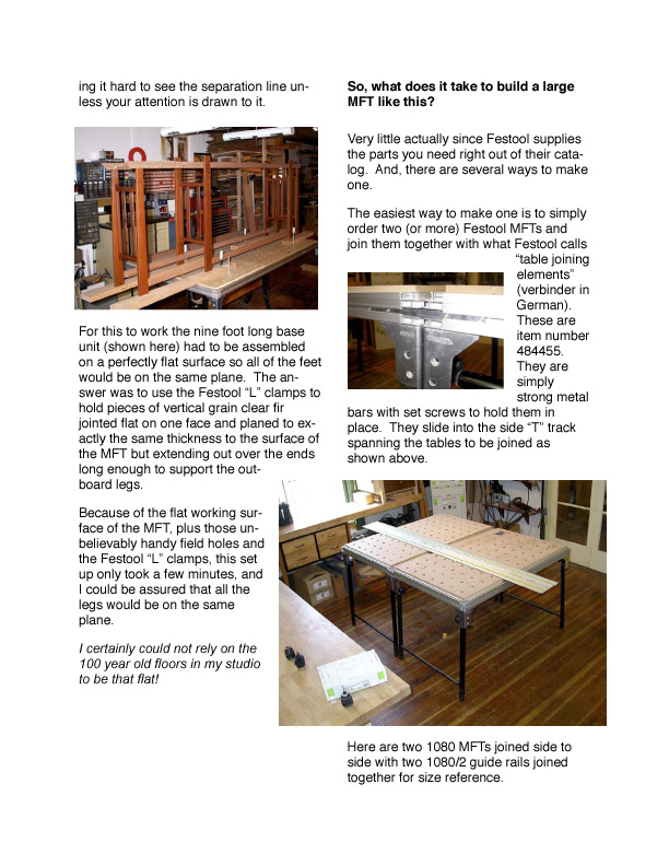
15 To join the tables side to side like this you will need to remove the factory side stops that are used to position the guide rail holding fixtures. With four sets of legs supporting the work surface, this large MFT will hold all the weight you could lift onto it. the photo below left you can see two table joining elements in the foreground and two guide rail joining elements in the background. The close up photo below shows the difference in thickness between guide rail joining units (center) and table joining units (outside). The picture above shows these same two 1080 MFTs joined together end to end to form a really long work surface. For size reference that is a nearly 8 foot long guide rail on the top. To fit two 1080 MFTs together end to end you need to fold up one set of legs as shown. With three sets of legs on the ground this work surface is also very sturdy and can take all the weight you would want to put on it. Another way to build a larger MFT You can also build larger MFTs using different catalog components. The three top plate MFT shown below and in many The table joining elements are similar to the guide rail joining elements discussed earlier but thicker to fit the T slots around the perimeter of the MFTs. In
 and table joining units (outside).")
. might be weaker than the one piece units.")

16 of the photos in this manual I built by ordering one 1080 MFT (item number ), one pair of two meter side rails - called table profile in the catalog (item number ), and two additional top plates called perforated plates in the catalog (item number ). might be weaker than the one piece units. It turns out the off cut piece of the third top plate makes a very handy straight edge with the same 20mm holes in it so it is a very usable jig on its own. To keep the top plates aligned with one another, vital to maintaining the flat work surface shown, I suggest cutting biscuit slots or a spline slot in each mating edge. Don t glue the biscuits or splines in place and don t glue the edges of the top plates either. You want to be able to easily replace a plate if it becomes damaged. The biscuits will swell up on their own just from the moisture in your shop so will hold quite firmly without any glue yet they can be removed later if necessary. I disassembled the MFT The side rails of the MFT 1080 became the end rails on this large table. The two meter table profile extrusions became the side rails and fit perfectly into the cast corner brackets of the MFT Since the perforated top plates are 725mm wide, three of them are longer than the 2 meter side rails. You have two choices. The one I elected was to cut down one of the top plates so the three would exactly fit inside the side and end extrusions. The only other thing you will need is a sturdy set of legs and some cross stringers that will sit under the table to reinforce where the plates join. As much as I like the sturdy Festool MFT legs, they are sized to fit on the ends of a 1080 MFT so The other option would be to cut off pieces from the end rails on the MFT 1080 and use them to extend the two meter table profile extrusions to just fit the overall length of three top plates side to side (2175mm). I m not sure it makes much difference, but I thought the two piece side rails


17 are not wide enough to fit on the sides of a 1080 MFT which are now the ends on this three plate MFT. I used a set of cast iron legs sourced out of Canada separated by fir stringers all held together with threaded tension rods. This makes a very sturdy leg assembly for this three top plate MFT which can be tightened if it ever begins to rack from day-in day-out use. Mine never has loosened and certainly does not rack so this set up has been ideal. You could also build a set of legs from any hard wood or from vertical grain clear fir or could modify the Festool leg set if you wished. I wanted this MFT to be higher than the Festool 1080 so I added a stringer on top of the legs that runs full length side to side. I used oak 60mm wide by 40mm deep, pocket hole screwed these into the top plates from below, and screwed them to the top of the cast iron leg set. Holding the top plates 40mm above the top of the cast iron legs made the overall table height just match the height of the table surfaces on the European combination machine that sits near this large Festool MFT. It is a comfortable working height for me but adjust your working height to be optimum for you and your shop or studio layout. In addition to all the work piece holding features and guide rail uses we will explore next, this work surface is also very handy for mundane things like setting out stock to select grain before machining as is shown in this picture. The final assembly detail is to place stringers across the table under the joints between each top plate. I used oak 20mm wide by 40mm deep pocket hole screwed into the bottom of the two adjoining top plates. This yields a work surface that has remained dead flat.


18 Squaring, clamping and work piece control When first considering a Festool MFT, most people seem to be drawn to the guide rail aspect of this system. As we will see shortly, that is an important feature, but the most common thing you will do day in and day out is hold work pieces in proper alignment while you work on or assemble them. And, I find the most common kind of alignment is squaring. No matter what kind of furniture you build, most likely some aspects of your piece will need to be assembled to be exactly square. If they are, your final piece will go together correctly, will sit flat on the floor, look good, and function the way you intended. If it is not square, the rest of the assembly can be a nightmare, and the finished piece rarely exhibits the quality you want. So while the act of squaring sounds simple, following the conventional practice of measuring diagonals and readjusting clamps, it is not. Here is a quick, simple and fool proof way to achieve nearly perfect square assemblies every time. Create a corner that is known square and clamp your assembly into that corner as is shown in the photo below. Position your clamps over the outside edge of the known square and over the opposite outside edge of your assembly. As you draw the clamps tight the assembly is drawn into the known square corner so it will also be square without any fiddling or measuring. Since this is such a common operation in furniture making, a squaring jig is one of the first things I suggest a new Festool MFT owner make for personal use. It can be made from any pieces of scrap, but, since you will be using it so often, I suggest you take a little time to make a nice squaring jig that you will enjoy using which exhibits a bit of the quality you want exemplified in your work. I made one leg from oak and one leg from walnut each 46mm wide by 26mm thick by 1210mm long. To make sure they never warp or twist and stay straight I suggest laminating two or more pieces together. Laminated wood remains far more stable than a single solid piece ever will. In my case I used two pieces 14mm thick and around 50mm wide. Once the glue fully cured, I machined the pieces to the final dimensions and used a 45 degree bevel cutter


19 mounted in a router to break the sharp edges. You want to be able to locate your squaring jig anywhere on the surface of the Festool MFT or on any side or end. It would be easy if 20mm dowel that would fit into the 20mm holes in the top surface of the MFT was readily available. It is not in most places. However, at nearly any hardware store you will find.5 female connectors designed for holding two pieces of.5 threaded rod together. It turns out these are almost exactly 20mm across the points so they fit the 20mm holes well and repeatedly. Epoxy one in one end of each arm of your squaring jig. Place it centered about 50mm from one end and 15mm from one edge. Allow it to stick out about 18mm from one face. That will make it recessed slightly on the other face if your components are the size I used. When you want to use this arm anywhere in the field of the MFT, just plop the projecting connector into one of the 20mm holes and screw in a 1/2 bolt with washer from the underside of the table to secure it in place. To make it even handier, epoxy a nut run up against the head of a 1/2 bolt and epoxy on a washer like the one shown next to the wrench in the photo below left. Now the head of the bolt and the nut make for an easy hand hold and the fixed washer allows one handed fastening. To make it easy to mount one of these arms into the T slots on the top of the outside extrusions on the Festool MFT, drill several 8mm holes centered on 20mm in from one edge. In the pictures these are drilled in the oak arm. Place 8mm bolts into these holes with the heads protruding down on the face opposite the face that has the 1/2 connector sticking out. These 8mm bolts will slide right into the T track and can be quickly tightened in


20 place. The 20mm edge to center line spacing of these hold down bolts will keep the edge of your squaring arm parallel with the top plate on the MFT which will provide extreme clamping strength without deflection. Use 1/4 toilet flange bolts if you prefer them to 8mm. They will function just as well. For the walnut arm insert the connector into one of the corner-most holes in the Festool MFT. Mark and drill an 8mm (or 1/4 ) hole centered over the T slot on the opposite side of the MFT. In use the 1/2 connector with a bolt securing it from the bottom and an 8mm bolt with its head in the T slot on the other side of the table will hold that arm very securely as shown in the photo below right. Now you have two arms almost 4 long which can be adjusted at nearly any angle relative to each other. The most common configuration for me is to put the first arm into the T slots on one long side of the Festool MFT secured with nuts and washers from above and the second arm into the corner most hole in the top plate of the MFT secured from below with the 1/2 bolt/nut/washer combination on one end and the bolt in the T slot on the other side of the table. measuring or secondary operations. It also will be flat because it can be held flat on top of the MFT top surface. Those 20mm holes and the nifty L shaped Festool clamps make it easy to clamp the assembly down to the table while you are drawing it into the known square corner. I use this set up for all kinds of things. Rail, stile and panel doors are a cinch to get right. So are drawers, boxes, frames, cabinet carcasses and just about anything else you can think of that needs to come out square and flat. Even flat mitered corners that normally squirm all over the place are easy to do. Just place one corner into your known square and place the large steel square over the opposite corner. Put two clamps going each way across your mitered piece. One end of the clamp goes over the outside of your squaring jig and the other goes over the outside of the steel I use a large steel engineer s square 250mm by 500mm by 10mm thick to create a perfectly square corner between these two arms. It only takes a minute to set up and the corner is known square. No matter what I want square, I can clamp it into that corner and know that when the glue dries the assembly will come out dead on square without any
 hole centered over the T slot on the opposite side of the MFT.")

21 square. Festool L clamps hold everything down flat against the top of the MFT. As you begin to tighten the clamps, the miters can easily be aligned to come out properly flush and perfectly square. Believe me, this is vastly easier than trying to do this with traditional corner clamps, band clamps or bar clamps! If you don t have a large steel square, simply use your known square corner to make a square of whatever size you wish out of whatever wood you have on hand. Reinforce the joint with a steel plate or hunk of baltic birch plywood, a few screws and some epoxy, and it will stay square for years to come. Don t use normal yellow or white wood glues as those tend to creep and might allow your square to become something else. The key is that you are clamping your assembly into a known square corner and, if you wish, with a known square on the opposite corner. Keep the assembly from twisting by tightening the Festool L shaped clamps to hold it tightly to the flat top surface of the MFT. This simple set up will save you hours of time and frustration on every project you do in the future. If you are like I am, you will likely say to yourself that you can justify the cost of the whole MFT set up with this one operation alone. You could do something very similar with any flat work surface, just not as easily or as quickly or as repeatedly. Best of all, your squaring arms can be used on a single MFT, or two or more MFTs joined together with the verbinders or on a three plate MFT with equal ease. You can use them along the edges as shown here or anywhere in the center of the MFT as we will see in subsequent chapters. One particularly nice application is to set up a known square with the apex aligned to the guide rail and each arm projecting out 45 degrees from the guide rail. Now you can cut perfect miters even if the guide rail is not set exactly 45 degrees to the two arms. Since the arms are 90 degrees to one another, if you cut the right miter against the right fence and the left miter against the left fence, the resulting joint will be exactly 90 degrees. If you are cutting molding or other trim, the corner you are fitting into often will not be exactly 90 degrees. No problem. Just set the squaring arms to whatever that angle is, cut the right side against the right squaring arm and the left side against the left arm and the trim will fit perfectly every time.


22 Keeping your MFT table top surface and squaring arms free of glue squeeze I often laugh when I ask first timers to my studio what they think the most dangerous tool in the place is. They invariably point to the big cutting tools like the shaper and table saw. They are surprised when I disagree with them and hold up instead a measuring tape with the comment that more accidents are made with a measuring tape than with any of those other tools. I usually follow this question with another, what is the most useful tool in the place? They generally ponder a bit knowing the first question had turned out to be tricky. This answer is a roll of white butcher paper mounted on my old fashioned (somewhat cluttered) sales counter, the one pictured here. Every time I want to glue something together, I rip off a piece of the butcher paper and place it on top of the MFT surface. The paper is less than 0.1mm thick (around.003 ) so it doesn t throw the assembly out of whack, but it sure does help to keep the MFT surface and the squaring arms clean. Butcher paper is hard enough to prevent the glue from bleeding through and yet absorbent enough to soak up some of the excess. The paper that gets glued to the work pieces comes off easily with the first sanding. Here is a sequence of photos to show how handy this can be. I tuck the paper under the squaring arms so it won t be in the way. Next the individual components get laid out for a final look before glue up. Clamp into the square corner and down flat on the surface of the MFT so you know your assembly will come out flat and square every time with no glue mess on your MFT.
23 Making glued up flat panels the easy way Many furniture projects require glued up panels. They may be used for tops, the panels in rail, style and panel doors, cabinet sides, dust shields between drawers, drawer bottoms or simply to get wide enough carcass pieces for the design you are building. Traditional wisdom says to joint the edges of two or more boards, plane them to all be exactly the same thickness, align them with biscuits or splines, clamp them together with clamps alternating over and under the panel and then hold the whole mess flat with cull boards clamped across the panel between each edge to edge clamp. The problem is that that rarely works very well or very easily. If you cut your biscuit or spline slots exactly the same distance from all the top edges and perfectly parallel with the top edges, the boards will likely align correctly, but the panel often will take on a bow just because some clamps are drawn more tightly than others. Or, if your cull boards don t have just the right amount of center down bow, they may not hold the panel flat side to side. With the Festool MFT you can make child s play out of this once frustrating process, and you can do so even if your boards are of differing thicknesses or if you don t want to take the time or have the ability to cut biscuit or spline slots accurately. The key is to clamp all your work pieces down to the surface of the Festool MFT while you are drawing them together with the side to side clamps. Being forced to a flat surface to begin with means that as the glue dries there is no tendency to warp or pull away from that flat surface so the panel comes out flat once the glue dries. If the boards are of different thicknesses, it won t matter because you are clamping what will be the top surface of all of the boards to the same flat surface so those edges will all align properly. I try to always take the time to properly prep my stock by jointing one face and one edge and then planing the other face and edge to be square, straight and parallel. While this adds a little time, it insures a proper outcome. We will talk a bit later about how to cut the edges to be glue line straight using the Festool guide rails and a Festool circular saw if you don t have a jointer or one of the right


24 size for the sizes of work pieces you are using for your panel glue up. fence that is really parallel with the cutter. Unfortunately, many are not. I also always take the time to cut biscuit slots aligned from what will become the top of the finished panel. By placing the fence of the biscuit joiner on the top of the work piece, I have good confidence that each biscuit slot will be very close to the same distance down from that face. Just make sure your biscuit joiner has a A good trick is to use one of the squaring arms you built earlier to act as a stop for the work piece so you don t have to rely only on down force to hold it in place as is shown in the photo above. Another thing to keep in mind is that the surface of the MFT stands proud of the aluminum side and end extrusions. This

25 space is very handy for cutting biscuits in thinner stock as shown here. Once the stock is prepped and the biscuit slots cut, I tear off pieces of the white butcher paper to cover the MFT surface where the glue lines will be. My technique is to apply glue first into the biscuit slots, then to both edges with a small paint brush. Next I insert the biscuits alternating piece to piece. The process of inserting the biscuit will normally force out some glue and I use the paint brush to apply that glue to the protruding edge of the biscuit. Once the pieces are aligned, I use a rubber dead hammer to bang them together and place the panel with what will be its top surface down on the surface of the MFT. I start with a bar clamp in roughly the middle of the panel. Before I draw it together, I use a Festool L clamp to hold the outside edges of the panel down flat on the MFT surface. Then I draw the clamp up tightly. I repeat this process proceeding from the middle out with a bar clamp about every 12 inches or so. In most cases the combination of the biscuits holding the faces in proper alignment, the joined edges mating at a true 90 degrees to the top of the MFT, and the Festool L clamps preventing the outboard edges of the glued up panel from lifting under the clamping force causes the glued up panel to lie perfectly flat and dry without clamp induced stress. On rare occasions when the stock is not properly prepped, the middle of the glue up may try to bow up. If this happens, just set a block down where it is trying to bow and use any old cull board and two more Festool L clamps outboard of the panel to force it down tightly to the MFT surface. The glue that squeezes out between the MFT and the panel is captured by the white butcher paper. The glue that squeezes out on the side facing you can be wiped off with a paper towel or you can leave it until it becomes a bit plastic and cut it off with a chisel or plane once the bar clamps are removed. Since I started doing this shortly after purchasing my first Festool MFT, I can t remember a glued up panel that didn t come out just right no matter how big. One picture on the next page shows part of a set of kitchen counter tops made from White Oak. Single pieces were over

 was held flat by the Festool table extensions set flush with the top of the MFT and the other (about a foot long) by a sandwich of 3/4 plywood culls.")
26 come out. Now I don t even think about it any more, it is so easy and repeatable. Also, there is no reason to do just one at a time. Fill the table with as many as it will hold to save your time. The large three plate MFT is shown above and the 2 feet wide and over 10 feet long. It was a heavy monster and I really appreciated the large MFT for that job! The glue up shown here is half of that unit. After both halves were done, I put them together the same way. The bulk of this glue up was held down flat on the top surface of the large MFT. One projected end (about two feet long) was held flat by the Festool table extensions set flush with the top of the MFT and the other (about a foot long) by a sandwich of 3/4 plywood culls. Even that large piece came out straight, flat and properly aligned. It took less than a.5mm pass (less than.020 ) on the wide belt sander to get everything perfectly flat and ready for final sanding and finish. In the past when I have been faced with large panel glue ups of this size, it was a real crap shoot as to how they would standard 1080 below.

27 This same process works just as well for small or thin panels as for large thick ones. I really like the look of book matched solid wood drawer bottoms and now find it easy to glue them up even for large drawers. Since a standard biscuit slot is 4mm thick and you need at least 2mm of wood on either side of the biscuit, you need to plan on drawer bottoms that are more than 8mm thick if you biscuit the edges. Since a drawer bottom is held all around its perimeter anyway, I find that I can simply edge glue panels down to 6mm thick for smaller drawers with little chance of failure. The picture to the right shows a simple looking but challenging glue up. It is multiple short boards glued to make a cross grain rather than long grain panel. Using the conventional one clamp up/ one clamp down process, multiple short boards like this will nearly always bow and twist. Doing it with the MFT, the glue up came out flat and straight - just as I expected.

 out towards each end. For portability the trestle top had to be removable from the side uprights but the joint not readily discernible, as shown in the photo below.")

28 The MFT is not just for square and flat objects So far we have talked mostly about how to use the MFT to make and hold square and flat objects. It works just as well for curved and three dimensional constructions as well. The strength and vibratory requirements dictated that the trestle be made from two pieces joined together in only two places by a short stretcher with sliding dovetail joints (shown in this picture made from blood wood) out towards each end. For portability the trestle top had to be removable from the side uprights but the joint not readily discernible, as shown in the photo below. For strength two dowels were required in the top of each upright to mate with each side of the trestle. This was all made far more complicated by the fact that the trestle was curved on both the bottom and top faces with varying radius curves. One example is using the MFT and one of the squaring arms you built earlier as a handy straight reference for oddly shaped pieces. The pictures show various steps in making a large gong stand from Brazilian Cherry, South African Blood Wood and Oregon Black Walnut. This unit holds a symphonic gong 36 in diameter that is quite heavy so the stand needed to be adequately strong. So, how in the world can you cut the four female sliding dovetail slots to exactly align both pieces of the trestle one with another while at the same time keeping the joint locating dowels properly aligned with the holes in the bottom of the trestle feet? One very laborious way would be to build a template jig, cut the dovetail slots and drill the dowel holes before cutting the curved top and bottom surfaces of each


29 side of the trestle. Given the sizes of the pieces, I found it far less labor intensive to cut the curved shapes first and do the Once in place the trestle could be moved up and down this cull board knowing that the flats on its mounting feet would always be 90 degrees to the guide rail even though the curved top edge might not be exactly symmetrical side to side. Next, dowel pieces were inserted into mounting holes and the second piece registered to the first with its inside face also pointing up away from the surface of the MFT. The two pieces of the trestle could then be moved to properly locate the router to cut the sliding dovetail recesses in both pieces at the same time. alignment for cutting the dovetail slots on the MFT with a Festool guide rail and router. That is where the squaring arm comes into play. It is easy to align the router to the intended line of cut using the mark on the front of the router base as shown. As a result, even though the two sides of I set the Festool guide rail into the included holder which fastens into the T slots on the side of the MFT. The squaring arm was then set to be 90 degrees to the guide rail. One trestle piece was placed with the bottoms of its mounting feet against the squaring arm and its inside face pointing up, away from the MFT surface. A second cull board was clamped with Festool L clamps to hold its face to the two points on its up-curved top edge. The squaring arm was then removed. the trestle were not necessarily the exact same shape and the two halves of either side were not necessarily exactly sym-


30 metrical, the dovetail slots cut in each kept them and the dowel holes perfectly aligned, something that would not be easy to do in any other way that I know. Once you start using the Festool MFT as your primary multi purpose jig like this, all kinds of applications will become apparent to you. Every day I have another aha!. Here is another example, this time placing four Lamello biscuit style brass hinges into two doors for a rail, stile and panel chest held together by sliding dovetails. The key is getting the doors and the sides properly aligned and held stable while you make the plunge mortise cuts for the hinges. I used the Festool L clamps to hold one side to the side of the large MFT standing proud from the surface by the width of the doors. The dovetailed dividers were inserted into this side and then into the other side standing upright on the surface of the MFT. Now both doors could be located in the opening in which they will live using washers all around to maintain the proper spacing. A pencil mark located the hinges and they were easy to plunge cut from this orientation. I really like these hinges, but they can be a challenge to align any other way. Another example is building a hall table with top shelves made from steamed eucalyptus and legs and lower shelf from highly figured Oregon Big Leaf Maple. The key here was gluing the stretcher dowels with the legs perfectly square so they would stand without wobble.

31 Using the MFT, Festool clamps, and the squaring arms built earlier, this was easily achievable. Two square corners were established on the MFT surface. Each leg assembly was clamped into these known square corners. The Festool clamps held the legs firmly against the surface of the MFT so nothing could move as the glue dried. upper, lower and side surfaces of the extruded table sides can help support work in upright and overhanging positions. The table surface can be extended to be wider and longer to match your work piece holding requirements. And, very importantly, a Festool guide rail can be set at any angle relative to your work piece and can be used to guide a circular saw, a router or a jig saw in an exactly straight line and at a known distance away from the surface of the MFT. Finally, with Festool table joining elements you can easily put together as many Festool MFTs as you need for the size of your work pieces. Now let s explore more about those Festool guide rails and how they can alter for the better how we work. From these few examples it is apparent that the Festool MFT provides three dimensional work piece positioning that is not at all obvious when you first look at a table surface full of holes, as first time viewers often describe the MFT. Though that first impression is apt, there is so much more than that to a Festool MFT. The holes are quite accurately positioned across the whole field so you can reference from anywhere with a simpleto-make squaring arm. The variety of Festool clamps can be positioned with the clamping element on either the top or the bottom surface and anywhere across the field so you can securely hold objects of nearly any shape. The T slots on the
32 Mirroring - Cutting the two interior walls of a cabinet carcass to be exactly the same As was discussed a bit in the introduction, one of the most important changes in how I build fine furniture occasioned by my use of the MFT is the ability to easily and quickly cut a series of dados, sliding dovetail slots, or component positioning lines in two or more work pieces at the same time. The most common thing you will use this for is cutting these slots in the two interior sides of a cabinet carcass to hold shelves or drawer guides. You will also use this for cutting such slots to hold upright components like interior walls or even to hold the sides of the carcass to the top and bottom of the cabinet. In fact, shortly after you start using the techniques we will cover in this chapter, I predict you will change for the better how you build all case goods in the future. While there is a bit of a learning curve to visualizing in three dimensions, within a short time you will regularly be doing such mirroring in all three dimensions: side to side, front to back, and bottom to top. It makes no difference whether you build your cabinet carcass from solid material, man made material or built up rail, stile and panel components. Once the components are nice and square, you will do the mirroring cuts the same way. While it is possible to make the cuts described here by a number of other means, I have yet to find any system that is as fast, reliable, accurate, and repeatable as is made possible using the Festool MFT, guide rails, and router. First, the MFT provides a flat surface and an easy way to hold your work pieces stable while making the cuts. Second, since the Festool guide rail holds the router in a straight line whether cutting with or against the rotation of the bit, you can cut in either direction accurately. Third, since you can hold the two sides of the work pieces together through the whole cut sequence, all the slots and marks will be in exactly the same place on both pieces no matter how many slots you need to cut. Finally, the ability to control the depth of cut with Festool routers with great accuracy makes possible multiple interlocking slid-
33 ing dovetail joints that you might never have imagined before. You need to start with components that are flat and square. We covered how to square most anything and how to make flat glue up panels in earlier chapters. Now let s combine these with mirroring. As an illustration of the techniques, we will follow along the construction of a real project for one of my clients. They wanted a small cabinet to house a flat panel TV, their audio video components on adjustable shelves behind a door, and some small speakers on either side of the door. The more traditional armoire style piece which completely hides the TV when closed would have been too big and dominant visually for their space and style. The room where this piece will live is done in an arts and crafts style with two wonderful Morris chairs, a period leather couch, and other furniture pieces I have built for them from Oregon black oak and Australian silky oak (often called lace wood in North America). This piece was to be made from the same wood combination with the TV sitting on top, a flapper door rather than swinging doors to hide the AV components, an open back for cooling and ease of cabling, and room on each side for the two small speakers. To fit the intended space it had to be no more than about 32 wide by 17 deep and 22 high. To fit the arts and crafts theme, a rail, style and panel construction was selected. The top was to be a single glued up piece of black oak. The bottom was to employ rail, stile and panel construction and be made from black oak. The outside sides which also would form the legs were to be rail, stile and slat components made from the silky oak. Inboard would be two rail, stile and panel uprights made from black oak and drilled for adjustable shelves which are made from glued up panels of black oak. The flapper door was to have silky oak rails and stiles with black oak panels. The front toe kick was to be silky oak. Since there would be no back, it was important to make sure the structure itself would provide plenty of rack resistance so the flapper door would work properly. The outsides slide into sliding dovetail slots in the underside of the top. The bottom slides into sliding dovetail slots cut on the inner faces of the outside compo-

34 nents. The inner uprights slide into sliding dovetail slots on the underside of the top and on the upper surface of the bottom rail, stile and panel component. The flapper door utilizes brass pins sliding in dados cut on the inside faces of the inner uprights and is supported at the front of the unit when in the open position by two more brass pins. All the sliding dovetail slots were to be stopped from the front so they would not show. So, here is a piece that has solid wood components, rail, stile and panel components, both dovetail and dado slots which run side to side, bottom to top and front to back. They are all stopped so they don t show from the front. And, it all has to go together rigidly with no back to add lateral support. This ought to be enough of a test to see if squaring, panel construction and mirroring using the Festool MFT can alter how you build just as it has altered how I build. To let the secret out early, I built this piece start to finish in less than one third the time I used to take making similar pieces. Therefore, I could sell a better quality piece less expensively. Also, the perceived value for my customer was much greater than it would have been had I followed past practice. Faster build time for me and a more precisely crafted piece add up to better value for my customer and a greater profit margin for me. That is what I call a good return on investment in tools, in this case the Festool MFT, guide rails, and router. Once the individual pieces were cut, all of the component assembly, squaring and mirroring cuts were done exclusively on the MFTs using a Festool guide rail and router. I work to a set of standards based around the metric system of measurements as it is far faster and less error prone for me to do so. In this case the piece is built to what I call a 50mm by 20mm by 10mm standard. That means that all the rails and stiles are 50mm wide by 20mm thick with 10mm wide and deep mortise and tenon joints. With modern glues these standards provide plenty of gluing surface for a strong assembly. All the dovetails are 10mm deep cut with a 20mm dovetail cutter. I like angles around 15 degrees so use the Festool router bit of these specs to make the cuts.


35 The math is quite simple. All I need to know is the overall outside dimensions of the piece in order to calculate the size of each assembly. Once the size of the assembly is known, then sizing the individual components is a snap. For example, the top on this piece is 820mm long and overhangs the sides by 20mm. Since the sides are 20mm thick, then the center lines of the dovetail grooves which will hold the sides to the top are 30mm in from each side and 760mm apart. The interior space between the inside uprights is 490mm so these two dovetail slots are 510mm center line to center line. Hence the center line spacing from the outer dovetail slots to each of the interior dovetail slots is 125mm. And so on. Let s start with the glue ups for the top and the various panels. As discussed in that chapter, making glue up panels is easy, fast and nearly fool proof using the MFT. Cut the individual boards to width and thickness, biscuit and clamp them together face down on top of a piece of paper on the MFT. Use Festool clamps to hold everything down flat on the surface of the MFT and draw the assembly together with bar clamps. Once the panels are glued up, they are cut to final dimension and sanded flat using up through 400 grit. In this case I used a small wide belt sander to flatten, but you could easily use the Festool Rotex or the linear sander as well. The rail and style components are all cut to overall size and then the corners are broken with a 45 degree Festool router bit number Either use the Festool router and edge guide working from the top or use a router table. I cut the grooves on the table saw portion of my European combination machine because it is faster for me, but they could just as easily be cut with a router and slotting cutter. I cut the shoulders for the end tenons on the sliding table saw and the sides of the tenons on the band saw, again, because it is the fastest way for me to cut them accurately and safely. They could just as easily be done on the shaper or less easily on a router table. They also can be cut on the MFT with a Festool router and guide rail.


36 Once you have the individual pieces cut to size as shown in this photo, the real fun begins. First, assemble the rail, stile and panel components. Make sure they come out flat and square using the techniques outlined in the chapters on glued up panels and squaring using the MFT. This is easy to do if you take a few moments to build squaring fences so top from glue squeeze out. With all the components in front of you, as shown here on top of the three plate MFT, it is time to cut the several dovetail slots and the grooves for the flapper door. I always start by cutting the female dovetail grooves first and then fitting the male dovetails to them later. Since both the outer sides and the upright you can clamp the component parts into a known square corner and clamp them down flat to the surface of the MFT. Again, use a piece of paper to protect the inner sides will connect to the top via sliding dovetails, that is a good first one to cut. Also, since the inner sides will also connect to the bottom via sliding dovetails, you want to make those cuts at the same time.


37 In the photo on the previous page, note how the top and bottom are laid out just as they will be on the assembled piece with their front edges aligned together. want for the dovetail grooves that will hold the outsides to the top. No room for measurement error here. With the guide rail clamped in position the router will be aligned with the intended line of cut, in this case the center line of the dovetail groove which will hold the inner side components to the top and bottom. Since we do not want these slots to show through from the front, the cut will stop about 30 to 40mm back from the front edge of each piece. You can see the pencil marks indicating where they are to stop in the photo to the left, but a simple way to site the stop is to use the handy side foot on the router as pictured on the previous page. That foot has marks for the centerline of the bit and 25mm forward and aft of centerline. Very nice. The edge of the bottom piece where the Festool clamp points to the left will get cut later with a male dovetail to slide into a matching female dovetail slot on the inner faces of the outer sides. A square is used to align the guide rail to be parallel with the sides of the top and bottom components and to make sure those two are properly aligned one with another. I recommend measuring from the center out to lay out both of the inner dovetail slots on the underside of the top. Use the edges of the bottom piece to mark the center lines for the dovetail groove that will receive the outer sides. Since the bottom piece will dovetail into the outer sides by 10mm and the outer sides are 20mm thick, the outside edge of the bottom will be exactly the center line you In this photo you can see the completed female dovetail slots cut in both the underside of the top and in the upper surface of the bottom at the same time so


38 they are perfectly aligned one with another. The next step is to cut the female dovetail grooves on the inside faces of the outer Notice in this case that the outer side components also form the legs so a toe kick has been cut out. To prevent the router from falling into this cut out, save the cut out pieces and position them as shown to give a good surface for the router stabilizing foot to slide across. sides which will receive the bottom. Just as the dovetails which hold the sides to the top and bottom run from the front to the back of the unit, so will these. The photo above shows the two outer sides face down on the MFT with their front edges aligned together. It is important for all these mirroring cuts to be made with the front edges held tightly together. The front edge is what you will see when the unit is assembled and you want these to line up perfectly. Any error in squareness will result in the back edges of the dovetail slots slightly misaligned, but the fronts will be spot on. Do not try to measure for the location of these dovetail slots. Instead, mark them directly off of the inner upright sides. Both the inner and the outer uprights dovetail 10mm into the top and the inner dovetails 10mm into the bottom. The bottom is 20mm thick, so you just need to line up the top edges of the inner and outer side components and mark the bottom of the inner side onto the outer side. That is exactly where you want the center line of the dovetail slot that holds the bottom to the sides to be. No room for measurement error here either.


39 The photo at the bottom of the previous page shows the slots cut in both sides at the same time so they are perfectly aligned. Note that they also stop short of the front edge so the joints will not show from the front. The Festool L clamps make it possible to hold everything in place. The next step is to drill the shelf bracket holes on the inner faces of the inside upright sides. I really like the Festool 32mm hole routing system for these cuts. guide rail make it simple to get all four rows of holes lined up just so. The third part of this system is the two guide rail aligning fixtures shown clamped to the guide rail and overhanging the edge of the work piece. The close up photo above shows the nifty offset marks on those aligning fixtures. Once you calibrate the fixture to the router base (a one time step,) you can set the offset where you want the center line of your shelf support holes to be from the edge of the work piece just by dialing it in. In the close up photo it is set for a 10mm set back, but you normally would want something more like 20 to 30mm. The system is made up of three major components as shown above. First is a guide rail that has slots machined in it that are precisely 32mm apart. A special router base plate shown at the lower right on the MFT rides on the guide rail and features a spring loaded indexing pin which will position the router to drill the holes. Note the black rocker handle in the middle of the special router base plate. Press either end to release the pin to allow you to index hole to hole very quickly. The combination of the easy to plunge Festool router with this base plate and This project is built to a mm standard so all of the rail and stile components are 50mm wide and 20mm thick. A set back of 25mm will place the shelf bracket holes right down the middle. The close up to the right shows the router in place on the base plate with the indexing pin lever in the foreground. The pointer is center line with where the shelf bracket will be drilled so it is easy to mark


40 the desired beginning and ending locations right on the guide rail with a pencil. Slick, fast and accurate. Here is a shot of the whole set up in use down from the top of the inner side upright components. Since they fit into 10mm deep dovetail slots, that will make your groove centered 25mm below the top. Set the 1/4 brass pin centered on the sides of the door down 28mm from the top. This will give enough clearance for the door to swing up and in easily. on this project. Note how the Festool L clamps come up from under the table to hold the guide rail to the work piece once the locating arms are removed. I use the Festool 5mm hole drilling router bit and it seems to stay sharp forever. With the female dovetail slots all cut and the shelf support holes all drilled, it is time to cut the stopped dado slots for the flapper door brass pins to ride in. Same steps again only this time with a grooving bit instead of a dovetail bit. I use a 1/4 brass rod riding in a 9mm groove. This combination does not bind, allowing the door to swing up and then in smoothly. Center the 9mm groove 35mm To cut the grooves, mark the center line and place the two inner side uprights face down on the MFT with their front edges together. Align the two so their top edges are flush. The photo above was taken after the male dovetails had been cut, but that makes no difference. Just keep the front faces together and the top edges aligned. Again, you will be cutting from the back edge towards the center stopping your cut this time 10mm from the front edge to the center of the router bit. That way the 20mm thick door will hang flush with or slightly recessed from the front edge of the inside upright components, just where you want it. Note in the photo above how the router stabilizing foot rides directly on the surface of the MFT. That way the router cannot tip on you and you can use the scale on that handy foot to stop where


41 you want to. In this case I used a small machinist square to locate the front and drew a line on the MFT with a pencil. In back from the front edge of the two inner side upright components. Next comes the dovetail slot that will hold the front toe kick to the two outer side components. This slot will run from the bottom of the two side components towards the top and will intersect the dovetail slot you just cut. You will make these cuts a bit differently but following the same mirroring technique. Place the two outer side components face down on the MFT bottom edge to bottom edge but with about a 40mm gap between them. Push these up against the fence and align the router to the center line as you did before. You will cut from the center space into each work piece stopping when the router bit passes into the dovetail slot you just cut to receive the bottom. All that is left now is to cut the male dovetails on the various ends of the respective pieces. making the cut I just stopped when the 10mm mark on the stabilizing foot was aligned with the pencil mark from both directions. Drill 1/4 holes for the flapper holding pins 40 mm down from the top and 80mm After that is done, before you do anything else, completely sand and finish all these component parts flat before assembly. Yes, that is right, sand and finish everything before you assemble the piece. Sanding flat components is a snap: no inside corners to try to reach and no awkward angles to reach into. For rail,


42 stile and panel construction I like the flat pad linear Festool RS-2 E plus sander. It is easier to keep flat on all these various a micro fiber pad as shown in the photo below. If there is any grain raised by the application of the oil, lightly buff the piece with the Rotex or RS115 rotary sander set in rotary mode with Festool Vlies pads attached. These are like 3M pads in that they will smooth out the finish without sanding through it. surfaces than a random orbit sander, and the square edges of the pad reach right into the corners on the panels without leaving scratch marks. I like to sand up to 400 grit for parts like these that will receive an oil and wax finish. A liberal coat of oil can be left to dry over night on nice smooth surfaces like these and you are ready for wax in the morning. The photo above shows all the components fully machined, sanded and finished. Not only is the sanding more easily done before assembly, so is the waxing. I like to apply the wax with a Festool RO- 150 Rotex sander set to rotary mode with I put mahogany colored wax on the silky oak and clear on the black oak. With the Rotex it is fast and easy to do three quick coats to make sure you have even coverage. Wait for the wax to dry (usually 15 to 30 minutes) and you can change to a buffing pad and use the same Rotex set to rotary mode to do the final polish. Since you are working on flat surfaces, this proceeds very quickly. The wax will


43 help all the sliding dovetails go together easily. With everything finished it is time to set the brass pins in the sides of the flapper door and in the inside uprights to hold the flapper door when open and pushed back into the cabinet. Now it is time to start assembling the piece. As the photo shows, the two interior uprights slide into the bottom which slides into the two outer sides. Now you can slide the top in place. Notice how easily everything goes together. No hammers, no straining, and for what some will find a shocker - NO GLUE. You will not use any glue when you assemble this piece. The dovetails alone will align and lock the piece together straight and true. Here is a quick tip on polishing those brass pins to look nice and glide smoothly. Chuck them in a drill and hold 3M pads around the pin while you turn it with the drill. Any gunk on the pins will be removed quickly and they will shine beautifully.


44 Note the engineer s square at the left front corner in this photo. Once the top is in place and the front toe kick locks the rest of the dovetails to provide the rack such bamboo pins under the name BBQ skewers with points on them to hold food together while it is cooking. For a piece like this I use bamboo pins that are about.130 to.150 in diameter, but the size does not matter. All the pins do is keep the dovetailed pieces registered within their grooves. The dovetail joints themselves provide all the needed strength. Drill a hole through the piece from the opposite side of the female dovetail slot and into the male dovetail about an inch or so. Place a bit of glue on the end of the bamboo pin and push it home. Cut off the protruding end and sand it flush with the surrounding surface. resistance, the piece squares itself in all directions. Any slight errors you might have introduced will usually cancel each other out. If you are going into light woods such as the black oak in this piece, sand with a linear sander so as not to burn the bamboo and it will virtually disappear. If going into dark woods such as walnut, sand with fine paper on a random orbit sander to burn the end of the bamboo making it dark enough so it will not show there either. You only need to pin the dovetails at the back of the piece as shown here to keep all of the expansion and contraction moving towards the front of the piece where it won t show. I use simple bamboo pins since bamboo is a grass rather than a wood and is resistant to breakage even in sheer. Most food stores sell


45 You don t need to be overly aggressive with the sanding. Only sand the pin flush without damaging the already finished surrounding surface. A bit of oil and wax and the pins simply go away visually. The nice thing is that if you ever want to disassemble the piece, all you need to do is to drill out those bamboo pins and the whole thing will come apart easily. The final step is to fit the flapper door. It should be the same width as the opening but 2mm shorter. Before you insert the brass pins into the sides of the door, do a trial fit. I like to resaw the door perfectly square registering off of the top of the door to leave 1mm spacing on each side. This photo shows how little it took to make the door perfectly fit the opening. A quick splash of oil followed by some wax and the cut sides look just like the rest of the piece. Insert the door from the rear with its brass pins registered in the dados and the front edge resting on the pin in the side of the interior uprights. A screw set into the dado groove at the rear prevents the door from sliding out the back. You are done! The pictures show just how easily the whole thing fits together. I usually call my wife down to the studio to stand by while I do a complex interlocking sliding dovetail assembly like this one as you never know when a minor warp might bind up one of the joints and you need a second pair of hands to recover. Without glue, recovery is almost always without trauma, but with glue in those dovetail joints recovery would be almost always impossible without breaking something. In this case, as in so many cases before, I called her down. She stood there watching all the parts simply go together - snick, snick, snick - and gave me that what am I doing here? bored look. You needed me? I have watched you assemble a bunch of pieces this way since you first bought the MFT. I have yet to see one that didn t go together that well! Better safe than sorry, I muttered. I know! she smiled, you wanted an audience to show off for and you just did! as we both admired the finished result you see here. What you have been following through this narrative took place from start to fin-
46 ish in one third the time it used to take me to build a similar piece. The precision is such that the components all fit together with a smooth, simple push. No hammers, no clamps, and no glue. Yet the piece is so stable and rack resistant that you have to open the flapper door to convince yourself that there is no back there to provide the stability more conventional cabinet construction techniques require. It is all made possible by the tight integration of the Festool MFT, guide rails, clamping systems, routers, sanders, and specialty components like the 32mm hole system. The keys are that with the MFT you can (1) quickly produce glued up panels of any size or thickness that come out really flat and nearly ready to use, (2) quickly square assemblies so they come out flat, square, and nearly ready to use, and (3) you can mirror matching cuts on two different work pieces quickly and easily. Combine these three techniques and you can change for the better how you build most kinds of fine furniture.


47 Cutting to exact size The Festool circular saws, jig saws and routers all come with a fitting that straddles an extruded hat shape in the top of each guide rail to allow the tool to move smoothly in a straight line. In the photo below the fitting is in the base of the Festool circular saw. The green line is a strip of slippery plastic that makes the saw glide easily along the surface of the guide rail. The black plastic fitting is an adjustable gib, shown in close up here. By tightening a set screw in the gib, the fitting can be made to move with little or no side to side play. Unlike guide rails that depend simply on the edge of a tool base gliding against the edge of a guide rail, the Festool system holds the cutting tool securely on line against both in thrust and out thrust forces. It is not your hands or eyes that keep the tool on line, it is the guide rail itself. The guide plate for the jig saw is on the left in this photo. The center and right guide plates are for the routers. The green protrusion is a micro adjust feature that allows you to position the router with great accuracy by lining up the mark on the base of the router with your intended line of cut. Once it is in position, you can be assured that your cut will be where you want it to be. Fully trapping the guide plates onto the guide rail is really important for cuts made with a router. In that case the rotation of the bit will try to pull the router into the work piece when you cut in one direction and away from the work piece when cutting in the other direction. In many mirror-

48 ing operations this is critical as you will need to make the cuts in opposite directions on each side of the cabinet carcass as was the case for the example piece we followed in the previous chapter. Each of the cutting tools provides a positive visual reference for where the center or edge of the cut will take place. For cuts with the circular saws a strip of rubber along the bottom edge of the guide rail is cut zero clearance to the saw blade with the first cut. From that point on you only need to align the rubber edge of the guide rail with the edge of the desired cut and you will be dead on accurate. In this photo you can see the rubber strip and a blade that has seen much use. (This blade will cut better after that gunk is cleaned off!) You can change the rubber strip if it gets nicked or if you change to a blade of a different thickness or blade set. The combination of the zero clearance strip on the guide rail with the no play hold of the base plate on the saw to the guide rail means that you can position the guide rail with great accuracy for all kinds of cuts. Just align the rubber edge on the guide rail with the edge of your intended line of cut and you will be right on every time. You have seen the V mark on the outside front edge and side of the base of the Festool routers denoting the center of the cut. Line that up with the intended line of cut and you will accurately follow your intended line of cut. To do so, place the guide rail parallel with and about 25mm or so away from the intended line of cut. Place the router guide stop shown on the previous page over the hat shape extruded into the top of the guide rail. Two steel bars attach to this fixture and pass through holes in the base of the router. Slide the router over until the V mark is aligned with your desired line of cut and tighten the router base to the two bars. The jig saw snaps into a recess molded into its guide stop, also shown on the previous page. On the front is a molded V mark indicating the center of that line of cut. The guide rails come in a variety of sizes and in two types. One type is intended just for guiding the hand power tools. The other has holes cut on 32mm centers to accept the special router guide stop which we discussed earlier. It features a spring loaded pin which indexes the router to exact 32mm spacing along the length of the guide rail. While intended


49 into the top and bottom of each guide rail. For work pieces which have no overhanging lip to clamp against, such as a box, Festool also supplies clamps which push horizontally along the bottom of the guide rail. mainly for drilling shelf bracket holes on 32mm centers with a router, as we did in the project we followed in the last chapter, the holes in these guide rails are handy for a variety of locating tasks. These are my favorite guide rails for every day use. The short one is 42.5 long and carries the mouthful name of FS1080/2-LR32. The long one is just under 8 feet and is called FS2424/2-LR32. The guide rails all have strips of soft rubber on the bottom side and strips of a slippery sliding compound on the top side. For many cutting operations they will stay in place just by the weight of your hand and the tool on the top of the guide stop. You can also clamp the guide rails to the work piece using any of the Festool L shaped clamps since the leg of the L is sized to slip into the T slots extruded The fourth means of aligning the guide rail with the work piece is by use of the MFT itself. Each table comes with a guide rail and a two part guide rail positioning system. One is a pivot which affixes to the bottom of the guide rail and slides into the T slots extruded into the sides of the MFT. A thumb wheel locks the pivot in place against a factory installed stop. A cam clamp allows the attached guide rail to be positioned up to 90mm (just under 4 ) above the table surface. On the opposite side of the table the second part of the guide rail positioning system also slides into the T slot extruded into the sides of the MFT and up against a factory installed stop. This component locks the other end of the guide rail into a fixed, known position as well as supports the guide rail at a known distance above the surface of the MFT. You can remove and reinstall these repeatedly and always know the line of cut will be in exactly the same place. Don t be afraid to use these guide rails in combination with one another. In this photo I am using a block to set the guide rail on the MFT surface to be 90 degrees to the guide rail bridging the MFT by

50 aligning to a large steel square that is in my left hand. The MFT also comes standard with a nice two component miter fence. A base unit affixes to the top of the MFT by two 20mm pins which fit through two of the the 20mm holes machined into the table top and is locked in place by tightening the included thumb nuts from the under side of the MFT. The miter fence itself is about 4 long and has a T slot on one side and on the top. The miter fence base unit slides into the side T slot so The miter fence base features an adjustable zero stop for initial calibration so you can set it to be exactly 90 degrees to the guide rail mounted to the sides of the table. The miter fence also has handy pin stops at 15, 22.5, 30, 45, 60, 67.5, 75 and 90 degrees. An included clamp which slides into the upper T slot on the end of the MFT holds the miter fence in the position selected. A handy length stop slides into the upper T slot in the miter fence so you can set it for repetitive cuts of the same length. Once calibrated, you can remove and remount the miter fence unit with great precision, returning to exact 90 degree cuts relative to the guide rail. Whether making cuts using a guide rail bridging the MFT or a guide rail clamped to the work piece directly, the key is to make sure the rubber edge is exactly aligned with your intended line of cut. It is that simple. When the intended line of cut is parallel with the edge of a work piece, I recommend doing the alignment at both ends of the guide rail with a story stick or steel rule rather than by measuring with the notoriously inaccurate steel tape. A story stick is just two pieces of scrap held together by a clamp of some sort. you can position the fence to be forward or aft of the base unit anywhere along its 48 length. Clamp a block on one end to overhang the edge of the work piece and extend the end of the other to be right where you want your line of cut. Clamp the two sticks together. You can move the story stick from one end to the other of the guide rail and achieve very accurate alignment. The only difficult alignment is where you want to rip or cross cut multiple pieces that are narrower or shorter than the guide rail. In this case place a scrap piece the same thickness as your work piece parallel to it to fully support the guide rail and keep it from tipping. Make

51 sure that the scrap piece is wide enough to project out the back edge of the guide rail. Measure and align the first piece just as you would for any cut. Before you make the cut, clamp the work piece down. Slide the scrap piece firmly up against the work piece under the guide rail and clamp it down. Now you have established a reference edge under the guide rail which you can use to align subsequent pieces for repetitive narrow cuts. will get piece after piece that is identical in size. Warning! Do not set a fence outboard of the rubber edge of the guide rail for cutting thin strips. Doing so will trap the cut off piece between the fence and the saw blade at the end of the cut and dangerous kick back is almost certain. Finally, it should be clear that using the Just be careful. The cut off piece will be under the guide rail and, while the riving knife on the Festool circular saw will limit kick back, it is still possible for the cut off piece to get thrown back by the blade. For really narrow cuts such as slats, you want those to fall to the outside of the cut line away from the blade and the guide rail. To ensure that happens, fashion another couple of story boards only this time clamp a block on either end. One block will go over the back edge of the guide rail. The other will be positioned to allow just enough of the work piece to project beyond the rubber strip on the guide rail to produce the desired width of cut off piece plus the width of the saw kerf. You might have to make a couple of test cuts to get really close, but it can be done easily. In use place the two story sticks at either end of the length of your work piece and hooked over the back of the guide rail. Push the work piece out to hit the blocks on the other end of each story stick and clamp your work piece down. Remove the story sticks and make your cut. Reset the story sticks, move the work piece out and repeat the process. You Festool guide rails and circular saw make previously tricky cuts such as tapers and cutting off the rough edge of an unsurfaced board a snap. Just align the guide rail with the desired line of cut and cut away. The photo above shows the guide rail and saw ready to remove the waney edge on this board cleanly. I keep a few pieces of thin plywood handy to hold the work piece off of the surface of the MFT to avoid cutting into it.

52 Conclusion There are many, many other uses for the Festool MFT that will become readily apparent to you as you use it. Also, there are any number of ways to utilize the other Festool hand power tools to help you improve the quality and efficiency of your work. While we have only scratched the surface in this manual, I hope you have seen enough to begin to use these techniques on your own. Squaring, flat panel glue ups, mirroring, holding all kinds of work pieces for all kinds of machining and assembly operations are what you will do day in and day out using the Festool MFT and accessories. Cutting and routing with precision and far better dust control will become common place if you also add the Festool circular saw, router and dust collector. Together these components represent a system that can change for the better how you work wood. By moving the rotating cutter in a carefully controlled path past the stationary work piece instead of the other way around, your woodworking future will be quite unlike your woodworking past. Jerry Work designs and hand crafts fine furniture in the 1907 Masonic Temple building in historic Kerby, Oregon. Enjoy!
Router Table Plans. www.bobsplans.com
 www.bobsplans.com Router Table Plans Increase the capabilities of your router with this weekend project. Features a sliding fence with EZ-Mount clamps. These clamps are simple to make and grip tightly
Gate Leg Drop Leaf Table Plans
 Preparing the table top blanks: Cut and glue enough 3/4 stock to make three panels 40 long by 24 wide (they will be cut to final size at a later time). While the glue dries we will work on the legs. Preparing
The tablesaw may be your shop s most valuable cutting. Crosscut Sleds. Foolproof. Innovative approach guarantees perfect results
 Foolproof Crosscut Sleds Innovative approach guarantees perfect results B Y A L A N T U R N E R The tablesaw may be your shop s most valuable cutting tool, but for precise, repeatable crosscuts it needs
Ladder Shelf Plans Final dimensions: 25 L x 21 W x 72 H
 Ladder Shelf Plans Final dimensions: 25 L x 21 W x 72 H Copyright 2011. MLCS Woodworking. Page 1 Router bits and supplies needed: 3/8 Rabbeting bit (#10691) 1 Bottom Cleaning bit (#7941) Top and Bottom
Installing Window and Door Mouldings
 Installing Window and Door Mouldings About Window and Door Mouldings The trim around windows and doors greatly influences the look and style of your interior. They also bridge the gaps and cover spaces
Wren Kitchens Installation Tips... 3. Carefully check your kitchen delivery... 4. Measuring out and marking up... 5. Fitting the base cabinets...
 tra 1 Index Wren Kitchens Installation Tips... 3 Carefully check your kitchen delivery... 4 Measuring out and marking up... 5 Fitting the base cabinets... 6 Fitting the corner cabinets... 7 The 972mm or
DIY CABINET REFACING INSTALLATION GUIDE
 DIY CABINET REFACING INSTALLATION GUIDE CABINET REFACING INSTALLATION Are you ready to reface your outdated cabinets? This guide will show you how to install your new Facelifters Cabinet Refacing Products
DIRECTIONS FOR ASSEMBLING BASE & WALL CABINETS
 DIRECTIONS FOR ASSEMBLING BASE & WALL CABINETS TheRTAStore.com STEP 1: CLEAR A WORK SPACE Place your RTA cabinet panels on a smooth, scratch resistant surface in a large, open area. (Some people like to
How to Build a Poker Table
 How to Build a Poker Table www.pokertablematerials.com 10-Person Poker Table- 96 x 48 These are step by step instructions for building a poker table. The table will measure 48" x 96" and have a 4" wide
How to Build Your Own CornHole Game
 How to Build Your Own CornHole Game DIMENSIONS Here is a diagram with the basic measurements for the Cornhole board game. SUPPLIES 1/2 thick sheet of plywood one 4 x4 or two 2 x4 s 8 long 2 4 s (4) 4 1/2
Cedar Cottage Doghouse Plans
 Overlapping cedar shingles add an element of charm to this medium size doghouse. The walls, floor, and trim are constructed of solid cedar, making it naturally weather resistant and provides excellent
Premier & Deluxe 3-Season Room Sliding Glass Door
 DTSSGD-11 Premier & Deluxe 3-Season Room Sliding Glass Door Installation Instructions Screen Door Seal Left Side Track Top Track Assembly Right Side Track Right Side Trim Sliding Glass Door Sliding Screen
Complete Dovetail Jig Instructions
 Complete Dovetail Jig Instructions 18 15 1 12 13 8 (22818) 19 17 16 4 3 6 14 5 9 9 11 10 2 PARTS LIST - COMPLETE DOVETAIL JIG Introduction Your new dovetail jig will cut Full Through Dovetails and three
www.cornholesupplies.com
 www.cornholesupplies.com How To Build Regulation Cornhole Boards Home of the Original Cornhole Bags and Boards Supply List: 1-4' X 8' Piece of Plywood (pre sanded) 4-2" X 4" X 8' Studs (2 by 4s make sure
KITCHENS. Tip PAGE 1 FITTING YOUR KITCHEN GUIDE. How to mark out a kitchen. Tools required for installing a kitchen STEP ONE STEP TWO STEP THREE
 FITTING YOUR KITCHEN GUIDE How to mark out a kitchen PAGE 1 Before starting on the installation, measure 870mm from the lowest point of the floor and mark a datum line around the room to indicate where
HOW TO INSTALL A BEAUTIFUL NEW KITCHEN
 HOW TO INSTALL A BEAUTIFUL NEW KITCHEN Easy to follow step-by-step kitchen cabinet installation TOOL AND MATERIAL LIST Hammer Pry bar Screwdriver Phillips Flathead Level Tape measure Pencil Straight edge
Advanced Cutting and Routing Techniques Using the Festool MFS Fence System
 Advanced Cutting and Routing Techniques Using the Festool MFS Fence System Text and Photos by Jerry Work Isn t it interesting how every so often a simple appearing new tool or technique comes along that
Children s Furniture Projects
 This is an excerpt from the book Children s Furniture Projects by Jeff Miller Copyright 2002 by The Taunton Press www.taunton.com CHILD S ROCKER KIDS ARE ALWAYS IN MOTION. It s not easy to get them even
Stair Parts Installation. Tricks
 Stair Parts Installation Tips & Tricks Introduction Your DIY staircase guide Welcome to the Stairpart home installation guide. Your stairway is both a functional and focal point in your home, so keeping
1958-64 WINDOW CHANNEL, WEATHERSTRIP & WHISKER STRIP REPLACEMENT FOR 2-DOOR SEDANS
 By Denny Williams Photos by Denny Williams 1958-64 WINDOW CHANNEL, WEATHERSTRIP & WHISKER STRIP REPLACEMENT FOR 2-DOOR SEDANS Denny Williams - Technical Writer Denny is first and foremost a dyed-in-thewool
Hive Top Ventilation Shims
 Hive Top Ventilation Shims When preparing your bee hives for the winter, it is very important to provide for ventilation at the top of the hive. Through out the winter, the bees are expelling a lot of
COMPLIMENTARY WOODWORKING PLAN
 COMPLIMENTARY WOODWORKING PLAN Adirondack Chair This downloadable plan is copyrighted. Please do not share or redistribute this plan in any way. It has been created for Wilton Tools, a division of WMH
RECLINE IN THE SUMMERTIME Get comfortable on the patio or deck with this sturdy reclining lounge chair
 RECLINE IN THE SUMMERTIME Get comfortable on the patio or deck with this sturdy reclining lounge chair As early as the eighth century B.C., the Greeks used a piece of furniture called the kline, for lounging
WHI 90-Minute Rated Veneered Door Frame Installation Instructions
 No. 940-03-10 INSTALLATION INSTRUCTIONS 90 MINUTE RATED VENEERED DOOR FRAME DOOR REQUIREMENTS: Consult the door manufacturer to make sure that the doors are qualified for the hardware to be installed,
C O N V E Y O R C O M P O N E N T S C H A I N S B E L T S B E A R I N G S
 C O N V E Y O R C O M P O N E N T S C H A I N S B E L T S B E A R I N G S January 2009 Issue 6 Valu Guide Brackets The Ultimate in Adjustability and Cost Savings Valu Guide brackets are part of a family
Garage Workbench Plans
 www.bobsplans.com Garage Workbench Plans Every home woodworker knows the importance of making efficient use of the available space in his or her shop. This workbench is designed to provide the maximum
Ceiling Mounted Folding Attic Ladders Installation Instructions
 Ceiling Mounted Folding Attic Ladders Installation Instructions WARNING Before you start installing your new Louisville Ceiling Mounted Folding Attic Ladder, you must read and understand the following:
Pole Lathe and Shave Horse Design
 Pole Lathe and Shave Horse Design These pictures and accompanying words are Copyright Michael Hughes February 2002. They are not to be re-produced, in part or whole, without permission from the author.
MGB Chrome Bumper Conversion
 MGB Chrome Bumper Conversion Installation Instructions For 1974 1/2-1980 MGB This kit requires cutting, welding, and painting. Professional installation recommended. Note: Every MGB body is slightly different
BUILDINGA 1/10 SCALE FLATBED TRAILER
 VOLUME 1, ISSUE 1 BUILDINGA 1/10 SCALE FLATBED TRAILER BUILT, DESIGNED & WRITTEN BY NATHAN MYERS MATERIALS: FEATURES: While the design was kept simple to allow anyone to be able to build their own trailer,
INSTALLATION INSTRUCTIONS for Bifold Doors (JII103)
") Thank you for selecting JELD-WEN products. Attached are JELD-WEN s recommended installation instructions for premium composite, hollow and solid core molded Bifold Doors. Bifolds are designed for fast
Thank you for selecting JELD-WEN products. Attached are JELD-WEN s recommended installation instructions for premium composite, hollow and solid core molded Bifold Doors. Bifolds are designed for fast
FTC 2015-2016 DIY Mountain Build Guide
 FTC 2015-2016 DIY Mountain Build Guide Assembly Instructions Check out the DIY2015-2016 Prints and BoM for individual part details. Release 1.0 9/10/15 Page 1 This guide and Bill of Materials are for constructing
Modular Locomotive System Instruction Manual for HBK8 George Body Kit
 Modular Locomotive System Instruction Manual for HBK8 George Body Kit Roundhouse Engineering Co. Ltd. Units 6-10 Churchill Business Park. Churchill Road, Wheatley. Doncaster. DN1 2TF. England. Tel. 01302
Chapter 3 Installing Over-the-Post Railing on an L-Shaped Stair
 49 Chapter 3 Installing Over-the-Post Railing on an L-Shaped Stair In this chapter: The Over-the-Post Balustrade System Determining the Rail Centerline Using Rail Bolts Making a Pitch Block Laying Out
SHELVES. www.tedswoodworking.com
 SHELVES It's rare that bookshelves look as interesting as the objects you display on them. After all, how much can you decorate the edges of your shelves and sides? This unit is unusual because the shelves
Build a Trade-Show Booth for Under $200!
 Build a Trade-Show Booth for Under $200! This corner booth, with a seven foot front and sweeping 4x8 backdrop, assembles in less than 20 minutes and can be built in one weekend. Materials Tools 4 x8 x3/4
Assembly Instructions Model 1544 Heart-Of-The-Kitchen Island
 Assembly Instructions Model 1544 Heart-Of-The-Kitchen Island A. These units are Ready-to-Assemble. Catskill uses positive fastening methods such as wood screws and in some places hidden Bastion fasteners.
Assembly Instructions Basic Folding-Leg Box Frame Style
 Assembly Instructions Basic Folding-Leg Box Frame Style Basic Folding Leg Cornhole Board Concept 1 2 12 3 1 2 3 15 16 4 1 4 52 9 R1 3 4 6 21 48 12 1 4 Bolt Washer 9 13 16 35 Washer Double Nut CornholePlayers.net
Lathe Milling Attachment
 Lathe Milling Attachment By L C. MASON BY CLEVERLY stacking cold-rolled flat stock together, T-slots and slide for this lathe milling attachment are made without costly machinery. In fact, only two tools,
Making Wooden Hinges
 Making Wooden Hinges By Alex Reid - www.mokkou.jp Materials and tools used - 3.2mm straight router bit - 1/8 round-over router bit - Flush-cut straight bit (with bearing on bottom) - Finger-joint jig -
DE Frame with C Series Sidelight
 TOOLS REQUIRED Tape measure 6' magnetic level 3' magnetic level Screw gun with clutch adjusted #2 phillips tip #3 phillips tip Screwdriver (used to adjust frame on will using oval slots) Pry Bar Powder
Responsibilities of a Volunteer Leader
 Responsibilities of a Volunteer Leader Inspecting tools for safe conditions. Removing unsafe tools from use and immediately notifying site supervisor. Teaching safe tool use to volunteers on your crew.
INSTRUCTIONS THOROUGHLY BEFORE BEGINNING***************
 Bill of Materials: RAC0012 Green Wing Aerodynamic Skirt Kit Item Part Number Description Quantity 1 RMC0218 Gen 2 Trailer Skirt Roadside 1 2 RMC0219 Gen 2 Trailer Skirt Curbside 1 3 RMC0041 Trailer Skirt
Magnetic Levitation Track Construction Instruction Manual August 2012
 This document is intended to be used by Science Olympiad teams to assist them in building a magnetically-levitated track that will meet all specifications in the event rules for Magnetic Levitation and
Go-kart for little race-drivers
 Go-kart for little race-drivers Drill and drive. Go-kart What it lacks in speed, it more than makes up for in fun: the go-kart will excite little race-drivers. 1 Introduction It s only a go-kart, but it
Black Wolf POCKET BILLIARD TABLE INSTALLATION MANUAL. SERVICE DEPARTMENT P.O. BOX 68 BRISTOL, WI 53104
 Black Wolf TM POCKET BILLIARD TABLE INSTALLATION MANUAL www.brunswickbilliards.com SERVICE DEPARTMENT P.O. BOX 68 BRISTOL, WI 53104 51-905710-000 SEPTEMBER 2010 NOTE: Please use the instructions in this
AZEK Rail Install Guide
 TRIM MOULDING DECK PORCH RAIL PAVERS AZEK Rail Install Guide Installing AZEK Rail with CableRail by Feeney... 1 Installing CableRail by Feeney for AZEK Rail... 7 Installing AZEK Rail Stairs with CableRail
POD Visor Instructions
 POD Visor Instructions Please read fully before beginning assembly and mounting the Visor Parts List - Visor Left Part (LV), Visor Right Part (RV) Qty 2, Aluminum Crossbars Hardware - Qty 17, 1/4" X 3/4"
HSC 2001 - Industrial Technology Band 4/5 INDUSTRIAL TECHNOLOGY FOLIO
 Statement of Intent I intend to construct a slim boy which will suit my needs and will be compatible with my furniture in my bedroom in my house. This will be very handy and useful to everyone in my home.
All-Season Sunroom Sliding Glass Door Installation Instructions
 ASRESGD-08 All-Season Sunroom Sliding Glass Door Installation Instructions Panel Frame Door Frame Left Side Foam Insulator IE241 H Bar Assembly Door Frame Top Track Panel Frame Door Frame Right Side Stationary
AstroSystems Digital Setting Circles for Zhumell, GSO, Apertura and Astro-Tech
 AstroSystems Digital Setting Circles for Zhumell, GSO, Apertura and Astro-Tech Components 1 Sky Commander Digital Setting Circle Computer 2 Encoders 10,000 step 1 Sky Commander Digital Setting Circle Manual
Installation Manual. SKU# 21000 series (Base Rails) SKU# 22000 series (Overhead Racks)
 SKU# 22000 series (Overhead Racks)") Installation Manual SKU# 21000 series (Base Rails) SKU# 22000 series (Overhead Racks) Welcome to the world of TracRac! We re delighted that you have chosen TracRac, the ultimate sliding truck rack system.
Installation Manual SKU# 21000 series (Base Rails) SKU# 22000 series (Overhead Racks) Welcome to the world of TracRac! We re delighted that you have chosen TracRac, the ultimate sliding truck rack system.
BUILD A TABLETOP LOOM
 BUILD A TABLETOP LOOM From 1" x 2" stock (actual 3/4" x 1"1/2) cut: 4 pieces 15" long 4 pieces 5"1/2 long Use the above to make 2 frames for the front and back of the loom. From 1" x 4" stock (actual 3/4"
CAST IRON THE BASICS. Heatline - Cast Iron Radiators SMOOTH FLAT FILE TO REMOVE ANY SWARF. ONE TIME. ASSEMBLY. JOINTS SHOULD BE TIGHTENED.
 CAST IRON THE BASICS 1. DO NOT LIFT ON YOUR OWN. 2. ONLY LIFT THE RADIATOR VERTICALLY. 3. DO NOT LIFT MORE THAN 8/10 SECTIONS AT ANY ONE TIME. 4. POSITION THE RADIATOR BEFORE FINAL ASSEMBLY. 5. THIS PRODUCT
Roll-Up Door Maintenance Guide
 R Roll-Up Door Maintenance Guide Cable Replacement on Two Spring Type Balancer Page 1 Panel Replacement - Removable Roller Cover Type Bottom Panel Page 1 Panel Replacement - Removable Roller Cover Type
Building The Modular Moveable Greenhouse described in The Four Season Farm Gardener s Cookbook By Barbara Damrosch and Eliot Coleman
 1 Building The Modular Moveable Greenhouse described in The Four Season Farm Gardener s Cookbook By Barbara Damrosch and Eliot Coleman This modular greenhouse is designed so home gardeners can easily build
2002 2005 Mini Cooper S Grille Install Instructions
 2002 2005 Mini Cooper S Grille Install Instructions Lower Front Grille BEFORE AFTER Package Contents 1 perforated grille (Stiletto, RAZR, or Monster) 6 Zip Tie Mounting Pads 1 is for the temp. sensor 5
Picnic Table Plans. Made out of a single sheet of plywood, it s also portable! By Kevin Ayer. This children's picnic table would
 Picnic Table Plans Made out of a single sheet of plywood, it s also portable! By Kevin Ayer Materials One 4- by 8-foot sheet of 3 4-inch AC plywood Twelve 11 4-inch wood screws Primer and exterior paint
Wine Rack & Glass Storage Bench Chris Gardner
 Wine Rack & Glass Storage Bench Chris Gardner Quantity Length Width Material Part 2 48 16 3/4 birch plywood top, bottom 2 14 16 3/4 birch plywood sides 2 14 13 3/4 birch plywood support dividers 2 3 15
The JIG is UP Or A couple hours up front pays in the long run.
 Ed Simon Page 1 of 5 The JIG is UP Or A couple hours up front pays in the long run. A large part of the fun of beekeeping is the construction and assembly of the equipment. Since it is a hobby, I decided
Assembly and Usage Instructions
 Assembly and Usage Instructions A Product 5885 West Van Horn Tavern Road Columbia, MO 65203 www.caldwellshooting.com Instruction #1001667 Limited Warranty Every Caldwell product is warrantied to be free
RadianceRail Installation Guide
 RadianceRail Installation Guide Installing RadianceRail with CableRail by Feeney... 2 Installing CableRail by Feeney for RadianceRail... 7 Installing RadianceRail Stairs with CableRail by Feeney... 10
Architectural Casework 06400-01. 1.01 Description of Work
 06400-01 1.01 Description of Work A. Extent of each type of architectural millwork and casework as indicated on drawings. Types of architectural casework shall include both stained and plastic laminated
2. This is a close up of a typical area where the rocker is rusted out leaving holes under where the rocker moulding would be..
 ROCKER PANELS 55,56,57 CHEVY REPLACEMENT Do not throw away any pieces when you first remove them. There are many supports that are not reproduced and will need to be used again. When disassembling try
Introduction to Door Construction
 Entry Door Construction Made Simple with Freud s Entry & Interior Door Router Bit System Congratulations on your purchase of Freud s Entry & Interior Door Router Bit System. This unique set allows you
Step by step guide to installing your own Ku Band satellite dish
 Step by step guide to installing your own Ku Band satellite dish If you don't feel comfortable installing your own system, your local TV Aerial or Handyman can easily follow these helpful guidelines for
UPLIFT Height Adjustable Standing Desk (T-Frame) DIRECTIONS FOR ASSEMBLY AND USE - - ALSO - - Watch our assembly video
 DIRECTIONS FOR ASSEMBLY AND USE - - ALSO - - Watch our assembly video") UPLIFT Height Adjustable Standing Desk (T-Frame) DIRECTIONS FOR ASSEMBLY AND USE - - ALSO - - Watch our assembly video http://bit.ly/9ywwh! CAUTION MAKE SURE NO OBSTACLES ARE IN THE DESK S PATH AND ALL
UPLIFT Height Adjustable Standing Desk (T-Frame) DIRECTIONS FOR ASSEMBLY AND USE - - ALSO - - Watch our assembly video http://bit.ly/9ywwh! CAUTION MAKE SURE NO OBSTACLES ARE IN THE DESK S PATH AND ALL
Panel/Hand Saw Kit Assembly Instructions
 Panel/Hand Saw Kit Assembly Instructions PLEASE READ THE FOLLOWING INSTRUCTIONS BEFORE BEGINNING Brief Summary You will be performing the following Tasks: 1. Determining the degree of shaping laying out
Speed-Mat Rectangle Cutter
 Speed-Mat Rectangle Cutter 1 Honeycomb baseboard. 2 Left hold down. 14 3 Bottom hold down. 4 4 Left / right rule. 8 5 8 5 Left / right rule pointer. 1 6 Top / bottom rule. 7 Top / bottom rule pointer.
Base Cabinet with Self-storing Folding Doors and Floor
 Usable Kitchens When designing a kitchen for use by persons with mobility impairments, especially those who use wheelchairs, careful layout of the kitchen is crucial to maintaining accessibility. People
Taking Wainscot Up Stairs
 Taking Wainscot Up Stairs raised MDF panels and stock moldings bring this elegant trim detail to the rest of the house BY GARY STRIEGLER I credit a lot of the success of my business to the trimwork we
glass & Glazing Products
 glass & Glazing Products WallMaker Create an unlimited variety of bright, beautiful and secure interior environments with the easy-to-install Stylmark WallMaker glass wall system. This versatile system
Vinyl Brick Mould Field Installation Instructions All Vinyl and Vinyl Clad Windows
 Vinyl Brick Mould Field Installation Instructions All Vinyl and Vinyl Clad Windows Viewed from the exterior. IMPORTANT: Please read before you begin installation. TABLE OF CONTENTS AND TOOL / MATERIAL
Dave s Sheet Metal Bending Brake
 Dave s Sheet Metal Bending Brake I started building a Zenith CH601XL from plans in mid January 2006. After several failed attempts to bend the rudder spar I ended up going to a local sheet metal shop for
Chelsea Loft Bed WARNING:
 Chelsea Loft Bed WARNING: Failure to follow these warnings and assembly instructions could result in serious injury or death. Read all instructions before assembling bunk bed. KEEP INSTRUCTIONS FOR FUTURE
SUPERCHIPPER CASTING MAINTENANCE
 INTRODUCTION By design, the Superchipper Rotor is clad in castings which wear during crushing. The castings wear at different rates depending on their location on the rotor, material feed rate, material
30 minutes in class, 2 hours to make the first time
 Asking questions and defining problems Developing and using models Planning and carrying out investigations 30 minutes in class, 2 hours to make the first time 3 12 x 24 x ¾ inch plywood boards 1 x 12
Raised Panel Doors Made Simple With Freud s 2+2 Raised Panel Bit Set
 Raised Panel Doors Made Simple With Freud s 2+2 Raised Panel Bit Set Congratulations on your purchase of Freud s world class 2 + 2 Raised Panel Bit Set. This revolutionary design combines two small wings
Section A. GENERAL INFORMATION
 Section A. GENERAL INFORMATION I. Description The information and instructions for attaching the sidecar to the right-hand side of the motorcycle are contained in this handbook and must be carefully observed.
FRONT BUMPER INSTALLATION INSTRUCTIONS 2007-2011 DODGE / MERCEDES SPRINTER
 Aluminess Products Inc 9402 Wheatlands Ct. #A Santee, CA 92071 619-449-9930 FRONT BUMPER INSTALLATION INSTRUCTIONS 2007-2011 DODGE / MERCEDES SPRINTER Please read before beginning Stainless steel hardware
The Hive Bodies. In the Beekeeper s Work Shop. Building a Bee Hive: The Hive Bodies. by Stephen E. Tilmann
 The Hive Bodies In the Beekeeper s Work Shop The hive body is the heart of a managed bee hive colony (Figure 1). It is where the queen lays her eggs, the house bees raise the brood and the workers store
Installation Instructions
 Installation Instructions 1. Position the unit onto bridging packers. These keep the unit away from any water sitting inside the frame. 2. Centralise the unit within the frame and pack the edges with appropriate
A Simple Approach to Raised-Panel
 A Simple Approach to Raised-Panel 82 FINE HOMEBUILDING Wainscot BY GARY STRIEGLER Stock molding and MDF panels transform a room 1 2 3 4 3 5 6 Raised-panel wainscot speaks of a time when craftsmen had an
Dock Hardware & Accessory Products Catalog
 Dock Hardware & Accessory Products Catalog Product Page # Product Page # Angle Brackets/Clips 8 Back Up Plate 5 Backing Plate/Hurricane Stop 10 Carriage Bolt Sets 4 Chain Retainer 10 Connector Pin Set
KITCHEN INSTALLATION GUIDE
 KITCHEN INSTALLATION GUIDE The step-by-step guide to installing your new kitchen right The materials and tools you ll need This brochure is your guide to preparing and installing your new kitchen. Inside
Guidelines for Earthquake Bracing of Residential Water Heaters
 Guidelines for Earthquake Bracing of Residential Water Heaters Department of General Services Division of the State Architect 1102 Q Street, Suite 5100 Sacramento, CA 95814 Phone: (916) 324-7099 Fax: (916)
CHARISMA SHOWER/TUB DOOR INSTALLATION INSTRUCTIONS
 CHARISMA SHOWER/TUB DOOR INSTALLATION INSTRUCTIONS IMPORTANT DreamLine reserves the right to alter, modify or redesign products at any time without prior notice. For the latest up-to-date technical drawings,
HALE PET DOOR INSTALLATION INSTRUCTIONS HALE STANDARD PANEL MODEL
 HALE PET DOOR INSTALLATION INSTRUCTIONS HALE STANDARD PANEL MODEL Please read these instructions carefully and completely before attempting to install Hale Pet Doors; they will guide you through the steps
TopSky DLG Installation Manual
 TopSky DLG Installation Manual Attention: Because after the compound materials solidify, there will be ammonia iris on the surface, which affect the bonding strength afterwards. Please polish with sandpaper
PROJECT PLAN. Stackable shelves
 PROJECT PLAN Stackable shelves This article originally appeared in The Family Handyman magazine. For subscription information, visit www.familyhandyman.com Please note that pages that appeared in the magazine
Router Table. Operating Procedures for
 Operating Procedures for Router Table INTRODUCTION: The router table is a very versatile tool. It can be used to cut a molding profile, cut workpieces to match the shape of a pattern and cut a molding
These instructions will show you how to install an internal door into a non-loadbearing partition wall. The instructions are split into three parts.
 No 8 in the series of 'How to' brochures produced by PlaceMakers, New Zealand How to Frame and Hang a Door These instructions will show you how to install an internal door into a non-loadbearing partition
SHOP NOTES METAL SHAPER FOR YOUR SHOP
 SHOP NOTES METAL SHAPER FOR YOUR SHOP A METAL SHAPER is indispensable for certain machining operations where flat surfaces must be produced within very close limits, such as machining flats on castings,
Retail Reception kiosk
 Retail Reception kiosk put 42" corner post in below 66" to allow post to extend above kiosk for raised box sign Mini cantilever option - 24" overhead support leg Mini cantilever option - 24" overhead 66/48E
DTU Animal Cart Programme
 DTU Animal Cart Programme TECHNICAL 21 RELEASE PIPE AND ROLLER DONKEY CART AXLES Development Technology Unit, Department of Engineering, University of Warwick, Coventry, CV4 7AL UK, tel: +44 (0)1203 523523
PRS X-axis E-chain installation: For tools with a 12 Z-Axis
 PRS X-axis Energy Chain (Echain) Installation Page -1- PRS X-axis E-chain installation: For tools with a 12 Z-Axis This kit is compatible with PRS Shopbots that have an X-axis cutting area of 96 to 144.
OHIO University Mechanical Engineering Summary Report: Human Power System for Small Appliances and Machinery
 OHIO University Mechanical Engineering Summary Report: Human Power System for Small Appliances and Machinery Appalachian Human Power Brad Bundy Ben Chovan Zach Fetchu Ed Passarrelli Ryan Tedford Will Zaylor
Installation Instructions For Slider Casement Air Conditioners
 Installation Instructions For Slider Casement Air Conditioners NOTE: These instructions describe installation in a typical wood framed window with a wood SLIDE-BY sash, or installation in a metal CASEMENT
How To Make A Spiral Fluted And Wire Wrapped Dagger Handle
 Making A Spiral Fluted and Wire Wrapped Dagger Handle By: Steve Culver, MS Part 1 Making A Spiral Fluted and Wire Wrapped Dagger Handle By: Steve Culver, MS After the rough handle material is drilled through
INSTRUCTIONS FOR CHAIN LINK INSTALLATION Chain Link fence & Posts Meshdirect.co.uk
 INSTRUCTIONS FOR CHAIN LINK INSTALLATION Chain Link fence & Posts Meshdirect.co.uk This guide explains how to correctly install our chain link fencing and post system. The guide provides details of the