FLAT ROOF CARPORT RECOMMENDED INSTRUCTION MANUAL
|
|
|
- Clare Bishop
- 10 years ago
- Views:
Transcription
1 FLAT ROOF CARPORT RECOMMENDED INSTRUCTION MANUAL

2 Table of Contents Introduction... 2 Components... 3 Step 1 Marking out the Perimeter of the Carport... 3 Step 2a Footing Set-Out for Concrete Block Pad Footing... 3 Step 2b Footing Set-Out for Concrete Slab... 4 Step 3 Preparation of Carport Posts... 5 Step 4 Post Sleeve on Base Plate Set-out... 6 Step 5 Preparation of Rafters... 7 Step 6 Assemble and Stand the Carport Post and the Rafter... 8 Step 7 Fixing of the Beam... 9 Step 8 Fixing of Roof Purlins... 9 Step 9 Plumb the Posts... 9 Step 10 Fix Base Plate Permanently... 9 Step 11 Carport Frame to be Square Step 12 Complete Fixing of the Frame Step 13 Gusset Plate Knee Brace Step 14 Fit Roof Sheeting Step 15 Fit Gutters and Flashings Step 16 Cut and fit downpipes Step 17 Finish

3 Introduction This Recommended Instruction Manual is a guide only. IT IS IMPERATIVE TO REFER TO THE ENGINEERING PLANS SUPPLIED WITH THIS MANUAL FOR SPECIFICATIONS AND DETAILS TO ALL THE CHAPTERS IN THIS MANUAL. Due to the large range of sizes and styles available, it is not possible to prepare an instruction manual for all styles, sizes and models. The following instruction manual is an EXAMPLE of a 6m wide x 6m long Flat Roof Carport. Things to do before you commence construction a. It is recommended to obtain professional advice to ensure your needs are adequately met. b. Check with your local government of any approval or restriction requirements. It is your responsibility to ensure that all approvals required are obtained. Safety Advice Important DISCLAIMER: This is a general safety advice. Refer to relevant state workplace authority website for safety advice on specific items and OH&S safety requirements. NOTE: Do not rely on this guide as exhaustive of all hazards that may exist on a construction site. Construction hazards must be assessed for risk and controls put in place to reduce the risk identified before commencing work. CHECK AND ENSURE THAT YOUR COMPONENTS ON SITE ARE CORRECT AND COMPLETE AS PER THE BILL OF MATERIALS. IF IN DOUBT, PLEASE CONTACT YOUR SUPPLIER. 2

4 Components Step 1 Marking out the Perimeter of the Carport Mark and set-out the perimeter of the Carport with pegs and strings. In this example, the size of the carport is 6.0m wide x 6.0m long. Refer to Engineering Plans for the actual size and specifications of your specific job. Step 2a Footing Set-Out for Concrete Block Pad Footing Mark and set-out the location of concrete pad footings to be excavated. The centre line of the posts is equivalent to the centre line of the pad footings. Using the string set-out of the perimeter as a guide, edge of the post is set in on the sidewall by the flange width of the Rafter. To determine the centreline of the post, add 1/2 of the post size to the flange width of the Rafter. Example: C150 Rafter has a 64mm flange width so the edge of the post is set in by 64mm from the string set-out. The post size is 75mm x 75mm so half of 75mm is 37.5mm. The centreline of the post is 64mm set in from the string set-out. The posts are set in on the endwall by 1300mm to centre line of posts as shown in Diagram Ab. Ensure that the diagonal measurements of the pad footings are equal, level and square. Refer to the Engineering Plans for size and specifications of the concrete pad footing. Dig out and pour concrete pad footings. 3

5 Step 2b Footing Set-Out for Concrete Slab Mark and set-out the edges of the concrete slab to be excavated. The edge of the slab is equivalent to the string set-out of the perimeter and using it as a guide, edge of the post is set in on the sidewall by the flange width of the Rafter. To determine the centreline of the post, add 1/2 of the post size to the flange width of the Rafter. Example: C150 Rafter has a 64mm flange width so the edge of the post is set in by 64mm from the string set-out. The post size is 75mm x 75mm so half of 75mm is 37.5mm. The centreline of the post is 64mm in from the concrete slab set-out. The posts are in on the endwall by 1300mm to centre line of posts as shown in Diagram As. Ensure that the diagonal measurements of the concrete slab are equal, level and square. Refer to the Engineering Plans for size and specifications of the concrete slab. TIP: Pegs and strings marking the perimeter of the building to be left in place until the position of base plates are clearly marked. 4

6 Step 3 Preparation of Carport Posts Check levels of footings and if required, cut posts accordingly to suit the building height requirements as the posts are supplied in stock lengths. Set-out and bore two holes at the top of the carport posts to match the punching (holes) detail of the C-Purlin Rafters. Refer to the Engineering Plans for the holes specifications. Size of holes and punching details vary according to the size of the C-Purlin Rafter. A table below is provided for the C-Purlin punching details for reference. The Rafter is to be bolted to the top of the post on an angle based on the roof pitch. Refer to the Engineering Plans for bolt size and specifications. 5

7 Set-out and bore two holes at the bottom of the carport post, punching details to be the same as the top of the post. Holes at bottom of post are only required if posts are to be bolted to the post sleeve on base plate fixed to concrete footing or slab. Refer to Diagram B. TIP: If Post is to be embedded, angle bracket at the base of the post with 2 tek screws is to be fixed in lieu of the bolt holes. Refer to Diagram C. You may stand the plumb post into the excavated holes and pour concrete at this stage or go to Step 5 to bolt the eave purlin to the posts before standing the posts. Step 4 Post Sleeve on Base Plate Set-out Using the set-out string marking the perimeter of the building as a guide, mark the position of the post sleeve on base plate. The post sleeve which is inserted to the bottom of the post is in on the sidewall by the flange width of the edge beam plus 1/2 of the post size and is in on the endwall by 1300mm from edge to centre line as shown in Diagram D. Fix the post sleeve on base plate to the concrete footing with fastening type as per the Engineering Plans. TIP: The centre line of post is equivalent to the centre line of post sleeve on base plate. NOTE: The post sleeve on base plate comes in 2-hole or 4-hole depending on the size and the requirements of the carport. Refer to the Engineering Plans for the specifications of the post sleeve. 6

8 Step 5 Preparation of Rafters On the outer web side of the Rafters, set-out and attach the shorter leg of the angle cleat bracket with 2 frame bolts. This bracket will be fitted inside the web of the beam. Refer to Diagram E. NOTE: Triangular carport knee braces run in two directions, along the sidewall between the rafter and the post and along the endwall between the beam and the post. Refer to Step 13 for detailed instructions of the Gusset Plate. 7

9 Step 6 Assemble and Stand the Carport Post and the Rafter Bolt the Rafter to the carport posts temporarily with the framing bolts supplied, one per column. Stand post in footing holes if embedded or insert the post over the post sleeve with base plate if not embedded. Refer to the Engineering Plans for specific footing requirements. Plumb the post and hold in place with 2 frame screws through the rafter into the post. Adjust and plumb the post as required. The bolts for this sidewall frame can now be completed and permanently tightened. Refer Diagram F. Repeat this process to erect the other Rafter. 8

10 Step 7 Fixing of the Beam Place the beam in position on the side of the front posts and bolt temporarily into the angle cleat attached to the rafter. Refer Diagram H. Repeat this step at the rear pair of posts. Step 8 Fixing of Roof Purlins Fit and bolt the general purpose bracket to the inner web face of the Roof purlins and the outer web of the Rafter. The beams at the low and high ends have the open side of the C-Purlin face out. Refer to Step 12 3D View. Step 9 Plumb the Posts Plumb the front posts on one side and temporarily brace it into position. Drill the remaining top hole and fit the second bolt. Plumb the rear post on the same side and fit the remaining bolt through the rafter. Step 10 Fix Base Plate Permanently Drill and fit masonry fixings to the base plates with post sleeve for posts that have been plumbed if base plate is required OR set concrete into the footing hole if embedment is required. 9

11 Step 11 Carport Frame to be Square Ensure the diagonals shown dotted are equal and prop the side that is not fixed into position. Refer Diagram K. TIP: Another option to use to check that the diagonals are equal is to calculate using this formula. Diagonal = square root (length 2 + width 2 ). Step 12 Complete Fixing of the Frame On the side that is on props, fix the remaining two posts to the Rafter. Plumb the posts then either bolt to the post sleeve with base plate or concrete them into position whichever is required. Ensure the rafters are on the correct roof pitch angle. Fit and permanently fix the long bolts supplied through to the post sleeve inside the base of the posts. TIP: If posts are embedded into concrete footings, it is recommended to wait for a few hours until 10

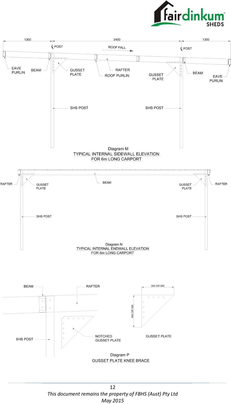
12 the concrete is set before starting on the roofing sheets. Step 13 Gusset Plate Knee Brace Gusset Plate knee brace are to be fitted in 2 different directions, along the sidewall between the outer flange of the end posts and the web of the rafter on 1 side only, Refer Diagram M. The endwall will have the gusset plate between the inner flange of the end posts and the web of the beams. Refer Diagram N. NOTE: Mid posts on longer carports have the gusset plate fitted between the web of the rafter and the outer flange of the mid post on 2 sides of the post. If fitted at this stage, the corner of the gusset plate will need to be notched 20mm both sides to allow for easy fitting. Refer Diagram P. 11

13 12
14 Step 14 Fit Roof Sheeting Lay the first sheet in position and ensure that the roof sheet is flush with the outside face of the rafter on the high end. This edge of the rafter should be pan fixed using wall screws to aid in the fitting of barge capping. If the frame is square, the first sheet should now be flushed along the length of the rafter. All other sheets may now be fixed at crest with the number of screws per sheet at supports specified on the Engineering Plans. Ensure that roofing sheets are turned up at the high end to prevent water running off this end. Step 15 Fit Gutters and Flashings Remove plastic cover protecting gutters and flashings before they are fitted. a) Fit the cover flashing to the gutter end of the roof b) Fit the stop ends and nozzle to the guttering c) Fit gutter brackets to the cover flashing with pop rivets. Ensure the brackets are fitted with a string line to the required fall location. d) Fit the gutter brackets into the gutter e) Fit side and head barge flashing and ensure that the bottom edge of the flashing is fixed to the bottom lip of the C-Purlin with pop rivets. Step 16 Cut and fit downpipes Cut and fit the downpipes to the drainage system. Step 17 Finish Remove any temporary bracing and check that all the required bolts and tek screws are fitted and tightened. BRUSH COMPLETE CARPORT DOWN WITH A SOFT BROOM TO REMOVE ANY METAL DUST/FILINGS CAUSED BY ANGLE GRINDER. CONGRATULATIONS ON A JOB WELL DONE! 13

Instruction Manual 19/9/01. Flat Roof Carport
 Flat Roof Carport Thank you for choosing this quality carport. We strongly recommend that you read these instructions thoroughly. The carport you are building may vary from a carport previously bought
FLAT ROOF BOX SPAN CARPORTS
 AGS/NC/03 FLAT ROOF BOX SPAN CARPORTS Thank you for choosing this quality product. We strongly recommend that you read these instructions thoroughly. Please take your time and do not rush the erection
STEEL BUILDINGS RECOMMENDED INSTALLATION GUIDE
 STEEL BUILDINGS RECOMMENDED INSTALLATION GUIDE 3 TO 30 METRE SPAN TILT UP METHOD SUPPLIED BY: Last update 8 December 2010 2010 FBHS (Aust) Pty Limited FBHS (Aust) Pty Limited ABN 83 126 232 504 trading
Construction Guide Skillion (Flat Roof) Patio Skillion Awning SKILLION CONSTRUCTION GUIDE 1
 Patio Skillion Awning SKILLION CONSTRUCTION GUIDE 1") Photographs are indicative only, and may contain elements not supplied in kit. Construction Guide Skillion (Flat Roof) Patio Skillion Awning SKILLION CONSTRUCTION GUIDE 1 Contents 1. Disclaimer... 2 2.
Photographs are indicative only, and may contain elements not supplied in kit. Construction Guide Skillion (Flat Roof) Patio Skillion Awning SKILLION CONSTRUCTION GUIDE 1 Contents 1. Disclaimer... 2 2.
Construction Guide. Pitched Roof Patio Pitched Roof Awning
 Construction Guide Pitched Roof Patio Pitched Roof Awning Photographs are indicative only, and may contain elements not supplied in kits. Add thousands of dollars value to your home Typically can be erected
SUPER SHED. Indoor shelter for your outdoor tools.
 SUPER SHED Indoor shelter for your outdoor tools. Not everyone needs a garden shed. But, if you've no more space on your garage wall for that new leaf rake, if you can't find your potting trowel because
Owner's Manual & Assembly Instructions
 Owner's Manual & Assembly Instructions BO01 PATIO COVER/CARPORT Model No. PC1010 Attached 705220511 Missing Parts, Questions on Assembly? Call: 1-800-851-1085 or [email protected] Do not return to
BUILD A CARPORT. 2 - Planning the carport. 3 - Designing the carport
 BUILD A CARPORT You only need basic DIY and woodworking skills to build a carport. The most important part of the job is setting the supporting posts truly vertical - a job for which another pair of hands
POST AND FRAME STRUCTURES (Pole Barns)
") POST AND FRAME STRUCTURES (Pole Barns) Post and frame structures. The following requirements serve as minimum standards for post and frame structures within all of the following structural limitations:
POST AND FRAME STRUCTURES (Pole Barns) Post and frame structures. The following requirements serve as minimum standards for post and frame structures within all of the following structural limitations:
How To Build A Gambrel Roof And A Gable End Roof
 Dutch Gable or Gambrel Roof and The Scotch Valley The folowing pages are an extract from Carp 12 text TAFE NSW Construction and Transport Division 71 HIP and VALLEY ROOFING GAMBREL / DUTCH GABLE The effect
MGB Chrome Bumper Conversion
 MGB Chrome Bumper Conversion Installation Instructions For 1974 1/2-1980 MGB This kit requires cutting, welding, and painting. Professional installation recommended. Note: Every MGB body is slightly different
Owner's Manual & Assembly Instructions
 Owner's Manual & Assembly Instructions BL01 PATIO COVER/CARPORT Model No. PC1020 Attached 705120511 Missing Parts, Questions on Assembly? Call: 1-800-851-1085 or [email protected] Do not return to
Best Barns USA Assembly Book
 Best Barns USA Assembly Book Revised November 27, 2013 the Easton - R 12'x 20' Manufactured by Reynolds Building Systems, Inc. 205 Arlington Drive Greenville, PA 16125 724-646-3775 This manual is copyrighted.
WorkSafe Guidance Document FALL PROTECTION IN RESIDENTIAL CONSTRUCTION
 WorkSafe Guidance Document FALL PROTECTION IN RESIDENTIAL CONSTRUCTION WorkSafe Guidance Document Fall Protection in Residential Construction Table of Contents Executive Summary... 1 Introduction... 1
UNIVERSAL ASSEMBLY INSTRUCTIONS FOR VERSATUBE BUILDINGS CONTRACTOR SERIES 2 X 4 FRAMES
 UNIVERSAL ASSEMBLY INSTRUCTIONS FOR VERSATUBE BUILDINGS CONTRACTOR SERIES 2 X 4 FRAMES Our unique assembly process quickly transforms the individual pieces into a finished structure that will give you
INSTALLATION. General. Important Note. Design. Transport
 General The roof trusses you are about to install have been manufactured to precise engineering standards. To ensure that the trusses perform as designed, it is essential that they be handled, erected
Leaky Homes Financial Assistance Package (FAP) Repair plan example
 Repair plan example") LEAKY HOMES FINANCIAL ASSISTANCE PACKAGE FACT SHEET Repair Plan Example - June 2014 Page 1 Leaky Homes Financial Assistance Package (FAP) Repair plan example Introduction This repair plan example is intended
LEAKY HOMES FINANCIAL ASSISTANCE PACKAGE FACT SHEET Repair Plan Example - June 2014 Page 1 Leaky Homes Financial Assistance Package (FAP) Repair plan example Introduction This repair plan example is intended
Installation Manual for STANDING SEAM ROOFING
 Installation Manual for STANDING SEAM ROOFING Absolute Steel Toll Free 877-833-3237 / Phone 480-768-1618 / Fax 480-768-1514 www.metalroofingsource.com Standing Seam features approximately one-inch high
Chapter 10 - Scaffolding Systems
 Chapter 10 - Scaffolding Systems Contents Chapter 10 - Scaffolding Systems... 10-1 Check and Oil the Pump Jacks... 10-4 Set Pump Jack Brackets... Error! Bookmark not defined. Set Pump Jack Poles... 10-5
March 14, 2007. Installation of Bay, Bow and Garden Windows
 March 14, 2007 Re: Installation of Bay, Bow and Garden Windows Attached are the Atrium Companies, Inc recommendation for the installation of bay, bow and garden windows. These instructions were developed
Installation Instructions Double-Hung, Single-Hung, Casement, Awning, Sliding, Picture & Shapes Non-Impact & Impact Resistant Nailing Fin Windows
 Installation Instructions Double-Hung, Single-Hung, Casement, Awning, Sliding, Picture & Shapes Non-Impact & Impact Resistant Nailing Fin Windows americancraftsmanwindows.com Project Requirements: Read
Installation Instructions For Slider Casement Air Conditioners
 Installation Instructions For Slider Casement Air Conditioners NOTE: These instructions describe installation in a typical wood framed window with a wood SLIDE-BY sash, or installation in a metal CASEMENT
HURRICANE MITIGATION RETROFITS FOR EXISTING SITE-BUILT SINGLE FAMILY RESIDENTIAL STRUCTURES
 HURRICANE MITIGATION RETROFITS FOR EXISTING SITE-BUILT SINGLE FAMILY RESIDENTIAL STRUCTURES 101 Retrofits Required. Pursuant to Section 553.844 553.884, Florida Statutes, strengthening of existing site-built,
PANELIZED HOME INSTALLATION GUIDELINE
 PANELIZED HOME INSTALLATION GUIDELINE A typical home package will be constructed of Snap-N-Lock Insulated Panels clad with steel skins. 4" panels will be used for the walls, and 6" panels for the roof.
OSHA GUIDANCE DOCUMENT FALL PROTECTION IN RESIDENTIAL CONSTRUCTION
 OSHA GUIDANCE DOCUMENT FALL PROTECTION IN RESIDENTIAL CONSTRUCTION OSHA GUIDANCE DOCUMENT FALL PROTECTION IN RESIDENTIAL CONSTRUCTION Table of Contents Executive Summary... 1 Introduction... 1 Installing
Installation Instructions
 Installation Instructions 1. Position the unit onto bridging packers. These keep the unit away from any water sitting inside the frame. 2. Centralise the unit within the frame and pack the edges with appropriate
Installation Instructions
 Installation Instructions One-Piece Deep Wall Sleeve For Use with Packaged Terminal Units Please read these instructions completely before attempting installation. NOTE: Ensure that the unit is only installed
FCA CARPENTRY & JOINERY THEORY. 10 SIMPLE ROOF CONSTRUCTION Part 2
 CARPENTRY & JOINERY FCA CARPENTRY & JOINERY THEORY 10 SIMPLE ROOF Double Roofs A double roof is a roof whose rafters are of such a length that they require an intermediate support. This support is usually
After reading this lesson you will be able to: 12.3 IMPORTANCE OF ROOF 12.4 TYPES OF ROOF IN A HOUSE
 86 :: Certificate in Construction Supervision (CIVIL) 12 ROOF 12.1 INTRODUCTION The structure provided to cover the house surface (floor) is known as roof. For different situation and requirement, it is
TYPICAL PATIO COVERS 111
 City of Laguna Niguel Building Division 30111 Crown Valley Pkwy Laguna Niguel, CA 92677 (949) 362-4360 FAX 362-4369 www.cityoflagunaniguel.org TYPICAL PATIO COVERS 111 PLEASE NOTE: This information Bulletin
Owner's Manual & Assembly Instructions
 Owner's Manual & Assembly Instructions PM01 BASE KIT Model No. FDN1014 717090311 CAUTION: SOME PARTS HAVE SHARP EDGES. CARE MUST BE TAKEN WHEN HANDLING THE VARIOUS PIECES TO AVOID A MISHAP. FOR SAFETY
Mark Cramer Inspection Services, Inc.
 Mark Cramer Inspection Services, Inc. 492 Twentieth Avenue, Indian Rocks Beach, FL 34635-2970 (727) 595-4211 Fax (727) 596-7583 Certified Member #12085 American Society of Home Inspectors Construction
Packaged Terminal Air Conditioner Wall Sleeve Installation
 Installation & Maintenance Data IM 1196 Group: PTAC Part Number: 910141799 Date: October 2013 Packaged Terminal Air Conditioner Installation x 42" PGAN with Top-Mounted Hydronic Heat Note: Installation
WHI 90-Minute Rated Veneered Door Frame Installation Instructions
 No. 940-03-10 INSTALLATION INSTRUCTIONS 90 MINUTE RATED VENEERED DOOR FRAME DOOR REQUIREMENTS: Consult the door manufacturer to make sure that the doors are qualified for the hardware to be installed,
STRUCTURAL CONCEPT FOR LIGHT GAUGE STEEL FRAME SYSTEM
 Chapter 9 STRUCTURAL CONCEPT FOR LIGHT GAUGE STEEL FRAME SYSTEM 9.1 BACKGROUND Steel is widely used in the construction of multi-storey buildings. However, steel construction is seldom used and is traditionally
Free 12 x 8 Shed Plan With Illustrations, Blueprints & Step By Step Details
 Free 12 x 8 Shed Plan With Illustrations, Blueprints & Step By Step Details Brought To You By: MyShedPlans Click Here To Download 12,000 Shed Plans >> 12 x 8 Basic Shed This 8 12-ft. shed features a simple
KAHU RESIDENTIAL ROOFING RRKA DETAIL LIST
 KAHU DETAIL LIST 00 / 24 COVER SHEET 01 / 24 ROOF RIDGE 02 / 24 SAWTOOTH RIDGE 03 / 24 SAWTOOTH EAVE 04 / 24 ROOF VALLEY 05 / 24 ROOF - CHANGE PITCH 06 / 24 EAVE WITH METALLINE FASCIA 07 / 24 EAVE WITH
Brick Veneer Construction
 Brick Veneer Construction Check list of suggested tools & support items Claw hammer Tape measure 3/4" [19 or 20] Wood chisel Wood or plastic shims Pry bar Utility knife Caulking and caulking gun Power
HORIZONTAL INSTALLATION
 THERMO/SOLAR Žiar s.r.o. MANUAL FOR INSTALLATION PV SUPPORTING FRAMES HORIZONTAL INSTALLATION Technical alternation reserved A1410 1 12/2014 CONTENT ORD.NO. PAGE Mounting information 3 Mounting, flat roof
ETL listed for installations within 5 ft. (1.5M) of outer edge of water www.srsmith.com 79-15152-00 Rev E2 9.14 Page 1 of 10
 of outer edge of water www.srsmith.com 79-15152-00 Rev E2 9.14 Page 1 of 10") Color Light Streams Large Laminar Installation Manual (CLSLL) Input Power: Total Power: 12V AC 5W 4008814 ETL listed for installations within 5 ft. (1.5M) of outer edge of water 79-15152-00 Rev E2 9.14
Color Light Streams Large Laminar Installation Manual (CLSLL) Input Power: Total Power: 12V AC 5W 4008814 ETL listed for installations within 5 ft. (1.5M) of outer edge of water 79-15152-00 Rev E2 9.14
Vinyl Greenhouse Window Page 2 of 6 New Contruction Installation Instructions
 New Construction Installation Instructions EPLACEMENT Installation Instructions Page 2 of 6 New Contruction Installation Instructions 1. Frame rough opening equal to window call out size. ough opening
PITCHED ROOF STRUCTURES
 PITCHED ROOF STRUCTURES for framed and frameless photovoltaic modules Needed tools and materials: cordless screwdriver 10mm and 13mm spanners 5mm Allen key bolts, screws and tools for fixing the system
Residential Deck Safety, Construction, and Repair
 Juneau Permit Center, 4 th Floor Marine View Center, (907)586-0770 This handout is designed to help you build your deck to comply with the 2006 International Residential Building code as modified by the
Chapter 3 Pre-Installation, Foundations and Piers
 Chapter 3 Pre-Installation, Foundations and Piers 3-1 Pre-Installation Establishes the minimum requirements for the siting, design, materials, access, and installation of manufactured dwellings, accessory
!!!!!! !!! Decra Plus DPSW010 DPSTW011 DPSW012 DPSW013 DPSW014 DPSW015 DPSW016 DPSW020 DPSW021 DPSW024 DPSW030 DPSW031 DPSW035 DPSW030 DPSW031 DPSW035
 Decra Plus Drawing no DPSW010 DPSTW011 DPSW012 DPSW013 DPSW014 DPSW015 Description Shown In Decra Brochure Most Commonly Used Detail t~êã=oççñ=b~îéë=aéí~áä=b~îéë=lîéêü~åö=táíü=fåëìä~íéç=c~ëåá~=~åç=pçññáí
Installation Instructions
 READ BEFORE INSTALLING UNIT For Slider Casement Air Conditioners To avoid risk of personal injury, property damage, or product damage due to the weight of this device and sharp edges that may be exposed:
Residential Foundations and Basements
 Residential Foundations and Basements Disclaimer All of the following information is based on the 2006 International Residential Code with Kentucky Amendments. As some information is paraphrased, article
Architectural Canopy Schematic Available in: Mill Finish & Anodized; Various Lengths & Alloys ENGINEERING AVAILABLE UPON REQUEST
 Architectural Canopy Schematic Available in: & Anodized; Various Lengths & Alloys ENGINEERING AVAILABLE UPON REQUEST Back Gutter Fascia Hanger Arm: Square Tube, Round Tube or Pipe Pans Architectural Canopy:
The WANZ Guide to Window Installation
 The WANZ Guide to Window Installation as described in E2/AS1 Amendment 5 Ver. 1.1 Page 2 of 74 Contents Overview Page 5 Objective Page 5 Scope Page 5 Opening Preparation Page 7 Step P1 Preliminary Check
SAMPLE INSTRUCTIONS. Best Barns USA Assembly Book. the Denver. 12'x 12' or 12'x16' Revised November 29, 2010
 Best Barns USA Assembly Book Revised November 29, 2010 SAMPLE INSTRUCTIONS the Denver 12'x 12' or 12'x16' Manufactured by Reynolds Building Systems, Inc. 205 Arlington Drive Greenville, PA 16125 724-646-3775
UBBINK SOLAR IN-ROOF SYSTEM
 UBBINK SOLAR IN-ROOF SYSTEM The integrated solar mounting system Installation guide UBBINK SOLAR IN-ROOF SYSTEM Table of contents Solar In-Roof System introduction System components Installation guide
Installation instruction do88 Intercooler for Volvo S40 / V50 / C30
 Installation instruction do88 Intercooler for Volvo S40 / V50 / C30 This instruction shows how to replace the OEM intercooler with our performance intercooler. 2. 3. 1. 4. 5. Part number: ICM-170 6. At
How To Repair A House
 Assessing Structural Damages Please note-this presentation is only intended to be used as a basic educational tool and is by no means all encompassing. Each property should be treated on a case by case
2.9 WINDOW & DOOR BUCKS
 2.9 WINDOW & DOOR BUCKS Bucks provide attachment surfaces for windows and doors while holding back concrete from these openings during concrete placement. Mark the center and edges of openings as you place
Hollow or Cinder Block Wall Mount Job Aid
 Summary This Job Aid covers: Hollow or Cinder Block Wall Mount Job Aid Hollow or Cinder Block wall Mount Bracket Installing the Mount Bracket into Cinder Block This Job Aid supports the Technician audience.
Installation Guide for Andersen Architectural Wood Inswing Entry Doors
 Installation Guide for Andersen Architectural Wood Inswing Entry Doors Congratulations! You have just purchased one of the many fine Andersen products. Proper assembly, installation and maintenance are
Clad Direct Glaze Window Installation Instructions
 Clad Direct Glaze Window Installation Instructions Sill flashing and sealing: 2. An overview of the proper flashing sequence is shown in figure 1. Please read entire installation instructions carefully
INSTRUCTION BOOK FOR. Lace And Grommet Theater-Type Screens
 INSTRUCTION BOOK FOR Lace And Grommet Theater-Type Screens Pre-Installation Da-Lite Lace and Grommet screens are custom made to meet the requirements for large surface installation of a relatively permanent
Fiberstars Lighted Laminar Flow Fountain Installation Manual
 Fiberstars Lighted Laminar Flow Fountain Installation Manual 79-15037-00 REV Xx http://www.fiberstars.com Page 1 of 8 SAVE THESE DIRECTIONS! These directions are provided to ensure the proper installation
STEADYfast Stabilizer Installation Notes Fifth Wheel and Travel Trailers 11/23/13
 STEADYfast Stabilizer Installation Notes Fifth Wheel and Travel Trailers 11/23/13 (See Supplemental Instructions for trailers with heavy duty round footplates and/or Power Leveling Systems) PHONE SUPPORT
Metal Free Standing Canopy Assembly Instructions
 Before assembly We recommend that time is taken to read the instructions before starting assembly, then follow the easy step by step guide. The instruction sheet is only a guide to the assembly. Certain
All-Season Sunroom Sliding Glass Door Installation Instructions
 ASRESGD-08 All-Season Sunroom Sliding Glass Door Installation Instructions Panel Frame Door Frame Left Side Foam Insulator IE241 H Bar Assembly Door Frame Top Track Panel Frame Door Frame Right Side Stationary
WINDOW INSTALLATION GUIDE FOR NEW CONSTRUCTION - WOOD FRAMING
 WINDOW INSTALLATION GUIDE FOR NEW CONSTRUCTION - WOOD FRAMING IMPORTANT NOTICES AND INFORMATION Read these instructions in their entirety prior to installing windows. Any local building code requirements
8/18/14. Introduction to. Framing. Terminology and Concepts
 8/18/14 Introduction to Framing Terminology and Concepts Terminology: Framing Level Two points on exactly the same horizontal plane. Square Intersecting lines or faces that form an exact 90 angle. Plumb
AA Solar and Sun Power Plus
 AA Solar and Sun Power Plus www.aasolar.co.nz www.sunpowerplus.co.nz -1- Contents Chapter Title Page 1 General information 3 2 Safety and Installer Responsibilities 4 3 Technical Specifications 5 4 Tools
INSTALL INSTRUCTIONS KK-C-HVAC-1 HVAC UNIT 2003-2014 CHEVROLET/GMC VANS FOR
 INSTALL INSTRUCTIONS KK-C-HVAC-1 HVAC UNIT 2003-2014 CHEVROLET/GMC VANS FOR (For NEW 2007 ALL WHITE KWIK-KITS ONLY) Warning do not attempt to install A/C units unless you are experienced with servicing
Cedar Cottage Doghouse Plans
 Overlapping cedar shingles add an element of charm to this medium size doghouse. The walls, floor, and trim are constructed of solid cedar, making it naturally weather resistant and provides excellent
Slide the new steering column shaft through the steering column from the driver compartment.
 Slide the new steering column shaft through the steering column from the driver compartment. Push the column shaft through the steering column until the machined end is out past the column lower bushing.
STANDARD OPEN PATIO COVER
 STANDARD OPEN PATIO COVER BUILDING & SAFETY DIVISION 201 E. LA HABRA BLVD. LA HABRA, CA 90631 62-90-9710 Call Before You Dig 1-800-227-2600 PLEASE NOTE: This information Bulletin is made available to assist
Page 2 of 6. Fittings Checklist. Care & Maintenance. Additional Tools Required. General Hints & Tips When
 MANHATTAN STORAGE BED PLEASE READ this sheet prior to assembly to familiarise yourself with the various stages of construction. Carefully open the pack supplied and check the contents against the parts
CARPENTRY - HOUSING. This is the sloping length of a right-angled triangle.
 CARPENTRY - HOUSING PART 2: GABLE ROOFS The gable roof is classified as being double-pitched and one of the simplest roof forms, due to the fact that all rafters in the roof are exactly the same length
LX STEEL BUILDING INSTALLATION MANUAL
 LX STEEL BUILDING INSTALLATION MANUAL A complete guide to the installation of the Quicken Mfg. LX Building and its accessories Copyright 2015 Quicken Manufacturing Inc. 16454 SE Hwy 19 Cross City, FL 32628
ROOF CONSTRUCTION Roof Styles Gable Roof Hip Roof Gambrel Roof
 ROOF CONSTRUCTION The overall appearance of a building is greatly affected by the roof lines and the roofing materials. The designer has many standard designs to choose from and should be able to find
Table of Contents. Safety... 3 Specifications... 4 Assembly... 5. Maintenance... 29 Warranty... 32 Parts Lists... 30
 Table of Contents Safety... 3 Specifications... 4 Assembly... 5 Maintenance... 29 Warranty... 32 Parts Lists... 30 WARNING SYMBOLS AND DEFINITIONS This is the safety alert symbol. It is used to alert you
AMERICAN GOTHIC PLAYHOUSE
 AMERICAN GOTHIC PLAYHOUSE Project Plan #856 Sheet 1 of 5 Pick a spot and get started with the beautiful that your kids will love. The design of the playhouse includes 35 square feet of interior space plus
300mm. 2mm MIN GAP. PLACE 100mm X 100mm. SO THAT IT IS 38mm INTO
 INSTALL PEEL & STICK (P&S) GUSSETS WITH PRIMER AS PER MANUFACTURERS INSTRUCTIONS 2mm MIN GAP IN SHEATHING STEP 1 PLACE 100mm X 100mm PIECE OF P&S IN CORNER SO THAT IT IS 38mm INTO THE OPENING EACH WAY
Manufactured Home Inspection Checklist
 Where building safety research leads to real-world solutions. Manufactured Home Inspection Checklist Nearly eight percent of the U.S. population lives in a manufactured home, according to the U.S. Census
Replacement Window Installation Guide Non-Impact & Impact Resistant Windows without Nailing Fin
 Replacement Window Installation Guide Non-Impact & Impact Resistant Windows without Nailing Fin americancraftsmanwindows.com Project Requirements: Failure to follow these instructions may void product
Classic Products, Inc. ClickLock Standing Seam Installation Manual
 Classic Products, Inc. ClickLock Standing Seam Installation Manual Classic Products, Inc. 8510 Industry Park Drive Piqua, OH 45356 800.543.8938 Table of Contents page Introduction 1. 1 Starter. 2. 1 Panels.
We urge you to read and follow the attached installation instructions. Failure to do so may void the warranty of this garden window unit.
 Important Information for New Construction Installations Attention Installer! We urge you to read and follow the attached installation instructions. Failure to do so may void the warranty of this garden
ISSUE 2. Installation Guide
 ISSUE 2 Installation Guide Here at Slide and Fold, we LOVE our Bi-Fold Plus range of folding-sliding doors. We want to ensure that your customers love them too. So we have created a new, detailed installation
Guidelines for Earthquake Bracing of Residential Water Heaters
 Guidelines for Earthquake Bracing of Residential Water Heaters Department of General Services Division of the State Architect 1102 Q Street, Suite 5100 Sacramento, CA 95814 Phone: (916) 324-7099 Fax: (916)
Owner's Manual & Assembly Instructions
 R0 Owner's Manual & Assembly Instructions Model No. EH08-A VL086-A WL08-A 697.686 709607 BUILDING DIMENSIONS * Size rounded off to the nearest foot CAUTION: SOME PARTS HAVE SHARP EDGES. CARE MUST BE TAKEN
Materials. Estimating Steel. Players. Materials. Shop Drawings. Detailing Process. Standard shapes. Fabricated members, Built-up sections
 Materials Standard shapes W sections, C channels, Structural T, Angles, Pipes, Tubes, Rods and Plates Fabricated members, Built-up sections Adding plates to beam flanges, Stiffeners to beam webs Built
How To Retaining Wall Guide
 How To Retaining Wall Guide Before you start: Consents and Engineering Building Consent Retaining walls over 1.5m high will require a building consent from the Local Body Council. Walls that carry extra
www.cornholesupplies.com
 www.cornholesupplies.com How To Build Regulation Cornhole Boards Home of the Original Cornhole Bags and Boards Supply List: 1-4' X 8' Piece of Plywood (pre sanded) 4-2" X 4" X 8' Studs (2 by 4s make sure
COMPLETE CONSERVATORIES K2 INSTALLATION GUIDE
 COMPLETE CONSERVATORIES CONTENTS SECTION NAME PAGE Introduction 3 Introduction - Victorian Roof Styles 6 Base Cill 7 Window Panels 10 Eaves Beam 17 Eaves Beam - Traditional 19 Firrings 21 Box Gutter 22
Basement Window Installation Guide Hopper and Sliding
 Basement Window Installation Guide Hopper and Sliding americancraftsmanwindows.com Project Requirements: Installation must comply with all applicable building codes. Existing window frame, wall and weatherresistant
Installation Guide for Andersen Architectural Clad Outswing Commercial Doors
 Installation Guide for Andersen Architectural Clad Outswing Commercial Doors Congratulations! You have just purchased one of the many fine Andersen products. Proper assembly, installation and maintenance
Vinyl Brick Mould Field Installation Instructions All Vinyl and Vinyl Clad Windows
 Vinyl Brick Mould Field Installation Instructions All Vinyl and Vinyl Clad Windows Viewed from the exterior. IMPORTANT: Please read before you begin installation. TABLE OF CONTENTS AND TOOL / MATERIAL
Elo Touch Solutions Wall-mounting Kit for the 5501L IDS Touchmonitors
 Installation Manual Elo Touch Solutions Wall-mounting Kit for the 5501L IDS Touchmonitors SW602206 Rev B Table of Contents Chapter 1: Safety Warning... 3 Chapter 2: Kit Contents... 4 Included in Kit...
The better way to build TM. Installation Manual. FOUNDATION SIPs & FROST WALLS SIPs
 The better way to build TM Installation Manual FOUNDATION SIPs & FROST WALLS SIPs February 2016 PWF FOUNDATION & FROST WALL SIPs Installation Manual Table of Contents Topics General Requirements...................................
TIMBER FRAME STANDARD DETAILS SEPTEMBER 09
 Building 1 Grosvenor Court, Hipley Street OLD WOKING, SURREY GU22 9LL Tel: +44 (0) 1483 769518 Fax: +44 (0) 1483 770863 E-mail: [email protected] Internet: www.silvatecdesign.com TIMBER FRAME STANDARD
IF YOU NEED A POLE BARN OR DIY KIT CALL NOW AND LETS MAKE A DEAL
 IF YOU NEED A POLE BARN OR DIY KIT CALL NOW AND LETS MAKE A DEAL Check out our Affordable Selection of DIY Pole Barn kit sizes and prices below. We offer a complete DIY pole barn kit plus independent experienced
8' W x 8' H or 10' H Peak Style Shelter Assembly Instructions
 ' W x ' H or ' H Peak Style Shelter Assembly Instructions Description ' x ' x ' Peak Style Shelter - Gray ' x ' x ' Peak Style Shelter - Gray Recommended Tools Please read instructions COMPLETELY before
AMS 120. EFT Guest Card Terminal & Refund unit
 AMS 120 EFT Guest Card Terminal & Refund unit ACCOUNT MANAGEMENT STATIONS Wall mounted kiosk offering Visitor card purchase and refund Card deposit EFT purchase, refund and loading Full statement facilities
GYPSUM AREA SEPARATION FIREWALLS GA-620-2011
 GYPSUM AREA SEPARATION FIREWALLS GA-620-2011 GA-620-2011 Copyright 2011 Gypsum Association All rights reserved. Printed in U.S.A. Characteristics, properties, or performance of materials or systems herein
COMMONLY USED RESIDENTIAL BUILDING CODES
 COMMONLY USED RESIDENTIAL BUILDING CODES INTERNATIONAL RESIDENTIAL CODE (2009) form revised 5/10 FOUNDATION 1. DESIGN OF FORMWORK. Section 1906.1 IBC 2009, Section R404.1.2.3.6 IRC 2009, ACI 318 Section
Information Technology Solutions
 Information Technology Solutions Aluminum Sliding Door Assembly Instructions Shield Doors & Windows Bi-fold Door Assembly Instructions For Support Please Call 03 8339 2252 Aluminum Sliding Door Assembly