A Practical Guide to Shaft Alignment
|
|
|
- Lucinda Hope Chapman
- 10 years ago
- Views:
Transcription
1 A Practical Guide to Shaft Alignment Care has been taken by the authors, PRUFTECHNIK LTD, in the preparation of this publication. It is not intended as a comprehensive guide to alignment of process machinery, nor is it a substitute for seeking professional advice or reference to the manufacturers of the machinery. No liability whatsoever can be accepted by PRUFTECHNIK LTD, PRUFTECHNIK AG or its subsidiaries for actions taken based on information contained in this publication. PRUFTECHNIK AG and/or its subsidiaries assume no responsibility directly or indirectly for any claims from third parties resulting from use or application of information contained in this handbook. 1 Edition 4; Copyright 2002 PRUFTECHNIK LTD All rights reserved Distributed in the U.S. by LUDECA Inc.

2 Introduction The purpose of producing this handbook is to provide basic information and guidelines for the implementation of good shaft alignment for standard rotating machine systems. Laser alignment is an essential component of a viable maintenance strategy for rotating machines. In isolation each strategy can help to reduce unexpected machine failure but taken together they form the hub of a proactive maintenance strategy that will not only identify incipient problems but allows extending machine operating life considerably. In each section of this handbook we have used one or two examples of the available methods for measuring the required parameters. We do not suggest that the methods illustrated are the only ones available. Prueftechnik are specialists in the alignment and monitoring of rotating machines, we have accumulated substantial practical knowledge of these subjects over the 30 years of our existence, in so doing we have produced many handbooks covering individual subjects and systems. This handbook is a distillation of this accumulated knowledge plus a brief overview in each section of the latest systems from Prueftechnik that address the specific applications concerned. We hope that this information is presented in a clear readable form and that it will provide for the reader new to the subject a platform to successfully apply profitable maintenance practice in their plant. We are indebted to our collegues in Prueftechnik AG (Germany) and our associates at LUDECA Inc. (USA) for permission to reproduce some of the graphics used in this handbook, additionally we have drawn on information previously published in Prueftechnik equipment handbooks for information on alignment standards, and graphical and mathematical methods of balance calculation. For this information we are grateful. 2

3 Introduction Shaft Alignment Page Number What is shaft alignment 6.. A definition 6.. Machine catenary 7.. Operation above critical speed 8 Expressing alignment 10.. Alignment parameters 10.. Angularity, gap and offset 11.. Short flexible couplings 14.. Spacer shafts 15 How precise should alignment be? 18.. Alignment tolerances 18 Troubleshooting 21.. Coupling strain and shaft deflection 21 Causes of machine breakdown 23.. Couplings and misalignment 23.. Bearings 24.. Seal wear 24.. Machine vibration 25.. Symptons of misalignment 25 Alignment methods and practice 27.. Machine installation guidelines 28.. Measurement and correction of soft foot 29 Alignment by Eyesight 33 3

4 Contents Page Number Alignment by Dial indicator 36.. Trial and error method 37.. Rim and face method - by calculation 38.. Reverse indicator method - by calculation 41.. Indicator bracket sag measurement 43 Alignment by Laser 45.. Basic operation requirements 48 Laser alignment case study.. Laser alignment cuts energy costs 52.. Laser alignment improves pump reliability 56.. Laser alignment improves bearing & seal life 58.. Laser alignment reduces vibration alarms 59 Thermal expansion of machines 60.. Thermal growth calculations 61 4

5 Shaft Alignment 5

6

7

8
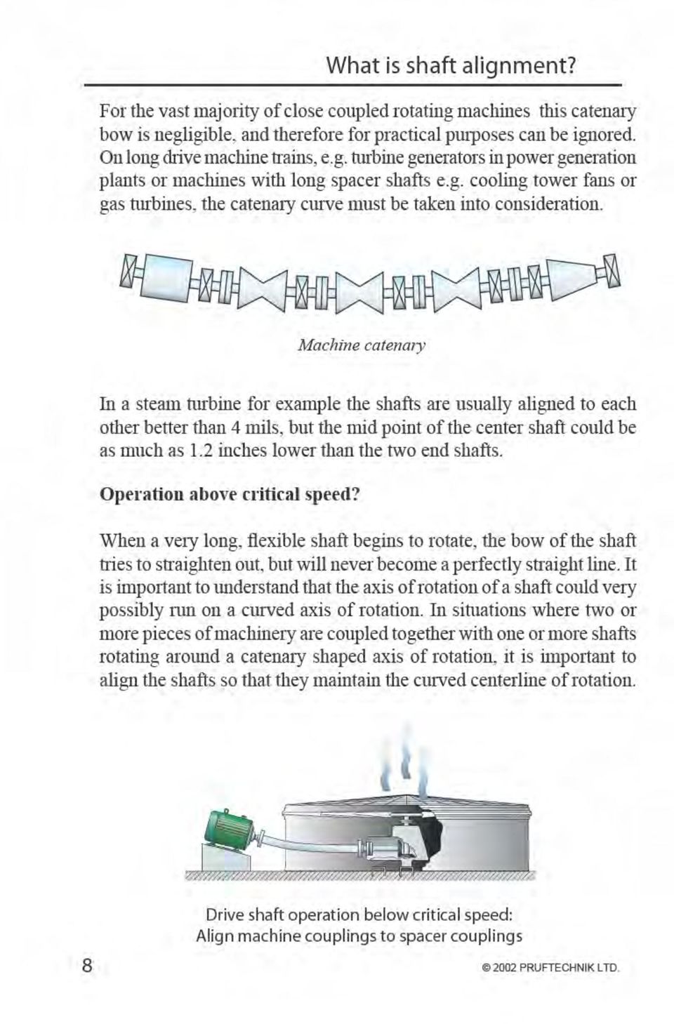
9 What is shaft alignment? Drive shaft operation above critical speed: Align machine couplings to one another ignoring spacer. 9

10

11
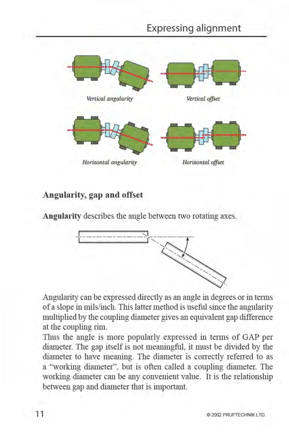
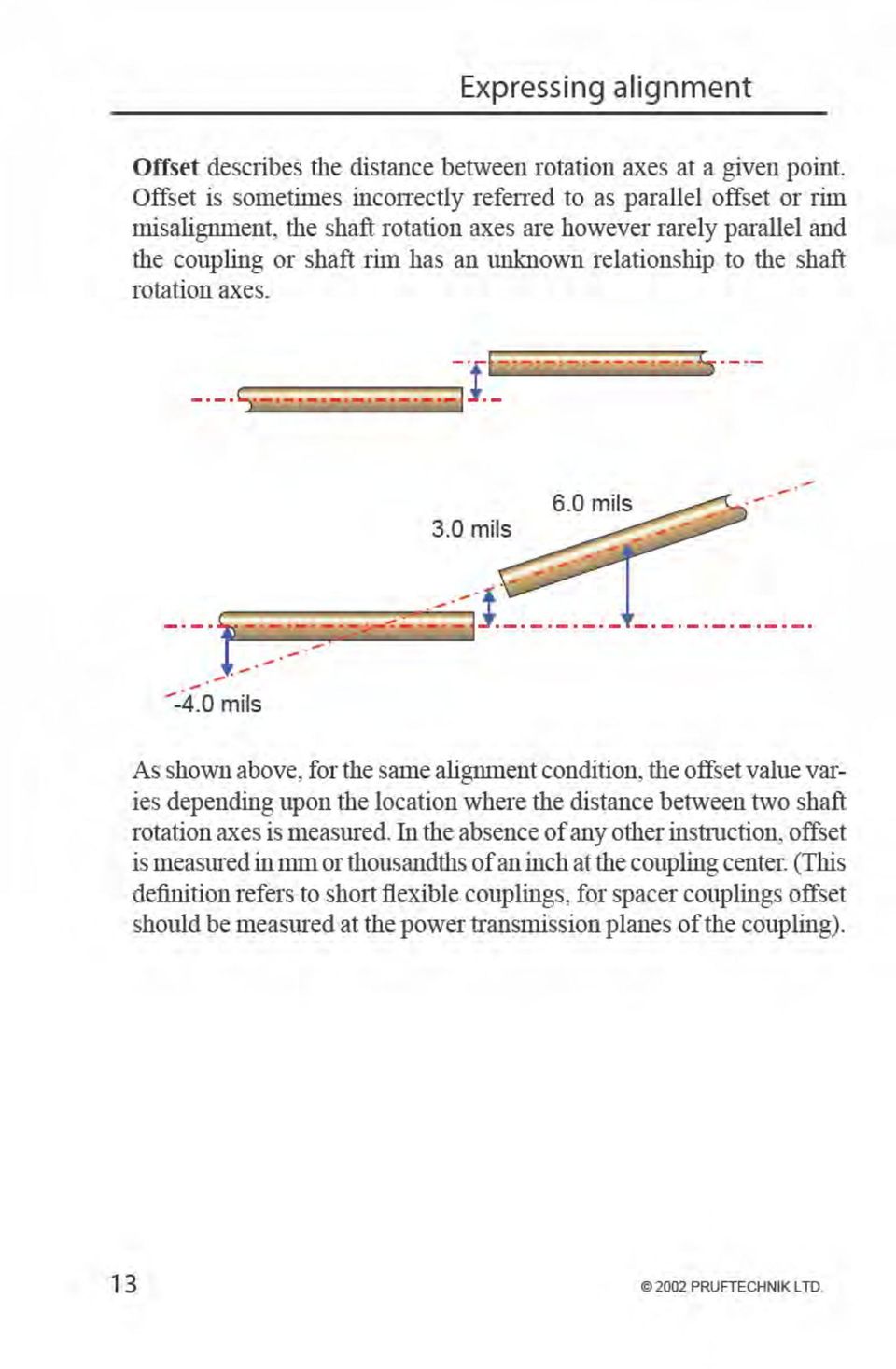
12

13
14

15

16

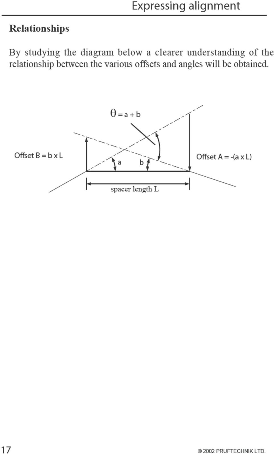
17
18 How precise should alignment be? Alignment tolerances for flexible couplings The suggested tolerances shown on the following pages are general values based upon over 20 years of shaft alignment experience at Prueftechnik and should not be exceeded. They should be used only if no other tolerances are prescribed by existing in-house standards or by the machine manufacturer. Consider all values to be the maximum allowable deviation from the alignment target, be it zero or some desired value to compensate for thermal growth. In most cases a quick glance at the table will tell whether coupling misalignment is allowable or not. As an example, a machine with a short flexible coupling running at 1800 RPM has coupling offsets of -1.6 mils vertically and 1.0 mil horizontally, both of these values fall within the excellent limit of 2.0 mils. Angularity is usually measured in terms of gap difference. For a given amount of angularity, the larger the diameter the wider the gap at the coupling rim (see page 12). The following table lists values for coupling diameters of 10 inches. For other coupling diameters multiply the value from the table by the appropriate factor. For example, a machine running at 1800 RPM has a coupling diameter of 3 inches. At this diameter the maximum allowable gap would be: 0.9 mils. For spacer shafts the table gives the maximum allowable offset for 1 inch of spacer shaft length. For example, a machine running at 1800 RPM with 12 inch of spacer shaft length would allow a maximum offset of: 0.6 mils/inch x 12 inches = 7.2 mils at either coupling at the ends of the spacer shaft. Rigid couplings have no tolerance for misalignment, they should be aligned as accurately as possible. 18

19 How precise should alignment be? Suggested alignment tolerance table 19

20 How precise should alignment be? Note For industrial equipment the amount of misalignment that can be tolerated is a function of many variables including RPM, power rating, coupling type, spacer length, design of coupled equipment and expectations of the user with respect to service life. Since it is not practical to consider all these variables in a reasonably useful alignment specification, some simplification of tolerances is necessary. Tolerances based on RPM and coupling spacer length were first published in the 1970 s. Many of the tolerances were based primarily on experience with lubricated gear type couplings. Experience has shown however that these tolerances are equally applicable to the vast majority of non lubricated coupling systems that employ flexible elements in their design. In the previous table acceptable limits are calculated from the sliding velocity of lubricated steel on steel, using a value of 0.5 inch/sec for allowable sliding velocity. Since these values also coincide with those derived from elastomer shear rates they can be applied to short flexible couplings with flexible elements. Excellent values are based on observation made on a wide variety of machines to determine critical misalignment for vibration. Compliance with these tolerances does not however guarantee vibration free operation. 20

21
22
23 Causes of machine breakdown Couplings can take misalignment? An often quoted comment is...why bother to align the machine when it is fitted with a flexible coupling designed to take misalignment? Experience and coupling manufacturers maximum misalignment recommendations would suggest otherwise. Anecdotal evidence suggests that as much as 50% of machine breakdowns can be directly attributed to incorrect shaft alignment. It is true that flexible couplings are designed to take misalignment, typically up to 400 mils or more radial offset of the shafts. But the load imposed on shafts, and thus the bearings and seals increase dramatically due to the reaction forces created within the coupling when misaligned. 23
24 Causes of machine breakdown Anti-friction Bearings Bearings are precision manufactured components designed to operate with clean lubrication and constant but restricted operating temperatures. Components manufactured within 0.2 mils accuracy are: Not able to withstand operating for long periods at elevated temperatures caused by misalignment. Not able to withstand contamination caused by mechanical seal failure which has allowed ingress of dirt, grit, metallic elements or other objects. Not manufactured to operate for long periods with misalignment imposing axial shock loads on the carefully machined and honed components. In addition to the damage imposed on the bearings through the misalignment itself, when mechanical seals fail, bearings have to be removed from the shaft assembly, sometimes re-fitted or in most cases replaced. Removal and re-fitting in itself can cause bearing damage. Most pump manufacturers and repairers recommend that when repairing damaged pumps, bearings should always be replaced irrespective of apparent condition, since it is easy to miss minor damage to the bearing that will progessively worsen after re-fitting. Mechanical Seals Seal wear increases due to shaft loading when shafts are misaligned. Pump seals are a high cost item often costing up to a third of the total pump cost. Poor installation and excessive shaft misalignment will substantially reduce seal life. Manufacturers have addressed the problem of poor installation practice by the introduction of cartridge type seals which can be installed with little or no site assembly. Seals however have precision ground and honed components with finished accuracy of 2 microns (0.08 mils) they do not tolerate operation in a poorly aligned condition, face rubbing, elevated temperatures and ingress of contaminants quickly damage expensive components. Seal failure is often catastrophic, giving little or no pre warning, the resultant plant downtime, seal replacement costs, pump repair costs and bearing replacements makes seal failure due to misalignment an expensive and unnecessary problem. 24
25 Causes of machine breakdown Machine vibration Machine vibration increases with misalignment. High vibration leads to fatigue of machine components and consequently to premature machine failure. The accumulated benefits of shaft alignment The benefits that accrue from adopting good shaft alignment practice begin with improved machine operating life thus ensuring plant availability when production requires it. Accurately aligned machinery will achieve the following results. Improve plant operating life and reliability Reduce costs of consumed spare parts such as seals and bearings Reduce maintenance labor costs Improve production plant availability Reduce production loss caused by plant failure Reduce the need for standby plant Improve plant operating safety Reduce costs of power consumption on the plant Push plant operation limits in times of production need Obtain better plant insurance rates through better operating practice and results 25 Symptoms of misalignment It is not always easy to detect misalignment on machinery that is running. The radial forces that are transmitted from shaft to shaft are difficult to measure externally. Using vibration analysis or infrared thermography it is possible to identify primary symptoms of misalignment such as high vibration readings in radial and axial directions or abnormal temperature gradients in machine casings, but without such instrumentation it is also possible to identify secondary machine problems which can indicate inaccurate shaft alignment.
26 Causes of machine breakdown Loose or broken foundation bolts. Loose shim packs or dowel pins. Excessive oil leakage at bearing seals. Loose or broken coupling bolts. Some flexible coupling designs run hot when misaligned. If the coupling has elastomeric elements look for rubber powder inside the coupling shroud. Similar pieces of equipment are vibrating less or have longer operating life. Unusual high rate of coupling failures or wear. Excessive amount of grease or oil inside coupling guards. Shafts are breaking or cracking at or close to the inboard bearings or coupling hubs. Good shaft alignment practice should be a key strategy in the maintenance of rotating machines. A machine properly aligned will be a reliable asset to the plant, it will be there when it is needed and will require less scheduled (and unscheduled) maintenance. In a later section we will review some specific case studies that will show how shaft alignment will deliver substantial cost benefits to operating plants. The next section of this handbook however will review the various methods of shaft alignment that can be used to deliver good installed machinery alignment. 26
27 Alignment methods and practices There are a number of different methods whereby acceptable rotating machine alignment can be achieved. These range from an inexpensive straight edge to the more sophisticated and inevitably more expensive laser systems. We can condense these methods into three basic categories, Eyesight straightedge and feeler gauges Dial indicators mechanical displacement gauges Laser optic alignment systems Within each category there are a number of variations and options, it is not the intention here to evaluate all of these options, instead we will concentrate on the most widely used methods in each category. Preparation is important The first preparatory step toward successful alignment is to ensure that the machine to be aligned may be moved as required: this includes vertical mobility upwards (using proper lifting equipment, of course) and downwards, should the machine require lowering, as is frequently the case. This can be achieved by inserting 2 to 4 mm ( ) of shims beneath the feet of both machines on initial installation (we recommend shimming both machines initially so that changes in the foundation condition may later be compensated, if need be). Horizontal positioning of machines is best performed using jack bolts or a simple machine puller tool or hydraulic equipment, all of which allow fine control of movement in a slow, gentle and continuous manner. Methods such as hammers not only make exact positioning more difficult but can damage machines (by causing chatter marks on bearings), but the vibration could displace the alignment system during the MOVE function and therefore lead to less accurate monitoring of correction positioning. 27
28 Alignment methods and practices Machine installation guidelines The installation of machinery such as a pump, gearbox or compressor etc. require some general rules to be followed. The driven unit is normally installed first, and the prime mover or motor is then aligned to the shaft of the driven unit. If the driven unit is driven through a gearbox, then the gearbox should be aligned to the driven unit and the driver aligned to the gear box. Basic checks should be carried out to determine the accuracy of the machine couplings, i.e. check for run-out (concentricity and squareness to the shaft centerlines) of coupling halves using a dial indicator, if possible (out of true coupling halves can cause out of balance problems!). Preparation of the machinery baseplate and machine mounting surfaces, feet, pedestals etc. is of paramount importance! Successful alignment cannot be easily achieved otherwise! Clean, dress up and file any burrs from mounting faces and anchor bolt holes etc. Have quality precut shims available to align precisely and effectively. Before assembling the shaft alignment system/ instrumentation to the machines, take a few minutes to look at the coupling/shaft alignment. Remember, your eyes are your first measuring system! Check that the pump/motor etc. is sitting square to the base plate. (Soft foot check) and correct as required - see following pages. Keep shims to a minimum i.e. no more than 3 shims maximum if possible under machinery feet/mounts. Correct alignment as required to ensure that, when the machinery is running, the machinery shafts are centered in their bearings and are aligned to manufacturers tolerances. 28
29 Alignment methods and practices Always check manufacturers alignment figures prior to commencing work! - temperature growth may require specific cold alignment offsets. Ensure that any pipework attached to machines is correctly supported but free to move with thermal expansion. Measurement and correction of soft foot An essential component of any successful alignment procedure is the determination and correction of soft foot. Just as a wobbly chair or table is an annoyance, a wobbly machine mount causes alignment frustration. The machine stands differently each time an alignment is attempted, and each set of readings indicate that the machine is still misaligned. Additionally when the machine is bolted down, strain is placed upon the machine casing and bearing housings. Essentially, there are three types of soft foot, two of which are illustrated in the sketch below. 29 Parallel soft foot indicates that the baseplate and machine foot are parallel to each other allowing correction by simply adding shims of the correct thickness. Angular soft foot is caused by the machine feet forming an angle between each other. This situation is more complex to diagnose and to correct. One solution is to use tapered shims to fill the angular space between the baseplate and the foot; a more drastic but long term solution is to remove the machine and grind the machine feet flat (or correct the angle of the baseplate)
30
31
32 Alignment methods and practices When eliminating soft foot follow these steps: 1) Check all four machine feet, any foot showing over 3.0 mils correct as appropriate. 2) Examine the largest (or two largest if the same) soft foot with feeler gauges to determine the type of soft foot. It never hurts to examine the other feet as well, but concentrate on finding and fixing the largest problem first. 3) Correct the condition diagnosed by shimming only one foot if any. 4) If all feet are within tolerance commence the alignment. 32
33 The straightedge Alignment methods - Eyesight This method of shaft alignment was common practice in many plants, provided a flexible coupling was used, it was considered good enough to eyeball the alignment and bolt the machine down. The equipment is certainly cheap and readily available. The corrective values for the machine feet were usually estimated according to the experience of the person carrying out the alignment. Most often corrections at machine feet need to be repeated on a trial and error basis before the eyeball alignment condition was completed. Even then there is no certainty that the completed alignment was correct. Since the resolution of the human eye is limited to 4.0 mils, alignment accuracy is correspondingly limited. Additionally without having carried out extensive checks on the fitting accuracy of the coupling on the shaft, no direct correlation between the completed alignment and the actual alignment of the machine shafts can be made. At best this alignment method can be described as coupling alignment not shaft alignment as defined earlier. 33
34 Alignment methods - Eyesight The feeler gauge Although classified here as an eyesight method of shaft alignment the feeler gauge method under certain circumstances and for some machines can be perfectly acceptable. In the installation and alignment of turbine sets where the coupling half is an integral part of the rotor shaft and has no flexible elements, it is possible for a skilled turbine engineer to align the two coupling halves very accurately. (As noted in the section on alignment tolerances, no allowance for offset or gap is permissible on these solid type of couplings) Using the feeler gauge or a vernier caliper the engineer accurately measures any gap between the coupling halves. Lift oil is then used to rotate the shafts together through 180 degrees and the gap is then checked again (with the lift oil off). This procedure is then carried out for the horizontal alignment measurements. 34
35 Alignment methods - Eyesight Readings are usually graphically plotted to establish alignment condition and any necessary corrections that are required. In some cases engineers will rotate one shaft through 180 degrees and take additional readings, these readings are then averaged to eliminate any possible shaft machining errors. The averaged readings form the basis for the alignment graph. On machines that employ flexible elements in the coupling design, the use of feeler gauges is beset with the same limitations as the straightedge method and can only be described as coupling alignment. 35
36 Alignment methods - Dial indicators The use of dial indicators for the vast majority of shaft alignment tasks where a flexible coupling element is used represents a substantial step forward in accurate shaft alignment methods. There are a number of dial set ups that can be used to effect the alignment of machines, this section will review some of these, however, there are also a number of factors that the engineer should take into account before embarking on a dial indicator alignment task. Indicator bracket sag: This should always be measured before actual alignment readings are taken - no matter how solid the bracket appears. See section on measuring sag. Internal friction / hysteresis: Sometimes the gauge has to be tapped in order for the indicator needle to settle on its final value. 1 mil resolution: Up to 0.5 mil rounding error may occur with each reading. This may be compounded several times in a full set of readings. Reading errors: Simple errors occur when dials are read under difficult conditions and severe time constraints. Play in mechanical linkage: slight amounts of play may go unnoticed but will produce large reading errors. Tilted dial indicators: The gauge may not be mounted perpendicular to the measurement surface so that part of the displacement reading is lost. Axial shaft play: This will affect face readings taken to measure angularity unless two axial gauges are used. 36
37
38
39 Alignment methods - Dial indicators Shim = (F6-F0+FS)(s)/dia -(R0-R6+RS)/2 Move = (HA)(s)-HO Move = (F9-F3)(s)/dia - (R3-R9)/2 If the dial indicators are set to zero at 12:00 and then read at 6:00, the shim calculation becomes: Shim = (F6+FS)(s)/dia + R6-RS/2 Positive result means add shims. Negative result means remove shims. If the dial indicators are set to zero at 3:00 and then read at 9:00 the MOVE calculation becomes: Move = (F9)(s)/dia + R9/2 Positive means move toward 3:00 Negative means move toward 9:00 The Shim and Move calculations must each be done twice, once for the front feet, and once for the back feet. Indicator reading validity rule. The sum of the 3 and 9 o clock readings should equal the sum of the 12 and 6 o clock readings. This applies to both radial and face readings. 39
40 Alignment methods - Dial indicators Where: R0 = Rim reading at 12:00 o clock position R3 = Rim reading at 3:00 o clock position R6 = Rim reading at 6:00 o clock position R9 = Rim reading at 9:00 o clock position F0 = Face reading at 12:00 o clock position F3 = Face reading at 3:00 o clock position F6 = Face reading at 6:00 o clock position F9 = Face reading at 9:00 o clock position dia = Diameter of the circle travelled by face indicator foot RS = Sag of Rim indicator FS = Sag of Face indicator * s = Span from measurement plane (rim indicator foot) to machine foot (front or back) This value can be positive or negative Clockwise is determined looking along shaft from MTBM towards STAT. Shim = (VA) (s)-vo Sag A major source of error in the above procedure is the sag of the spanner bar. This error can affect the shim amounts to such an extent that the machine will be grossly misaligned. To compensate for this sag, measure it and then add the sag reading (it can be positive or negative) to the 6:00 readings. See the above formulas. 40
41
42 Alignment methods - Dial indicators Where: S0 = Left rim reading at 12 o clock S3 = Left rim reading at 3 o clock S6 = Left rim reading at 6 o clock S9 = Left rim reading at 9 o clock M0 = Right rim reading at 12 o clock M3 = Right rim reading at 3 o clock M6 = Right rim reading at 6 o clock M9 = Right rim reading at 9 o clock d = Distance between left and right indicators c = Distance between left indicator and coupling center SS = sag of left rim indicator (1) MS = sag of right rim indicator (1) (1) these values can be positive or negative The corrections at the right machine feet can be calculated as follows: Shim left feet = (VA - sl) - VO Shim right feet = (VA - sr) - VO Positive result means add shim, negative result means remove shim. Shim left feet = (VA -sl) - VO Shim right feet = (VA -sr) - VO Positive result means move towards 3 o clock, negative means move toward 9 o clock. sl = Distance from the coupling center to left feet of right m ce sr = Distance from the coupling center to right feet of right m ce. If the dial indicators are set to zero at 12 o clock and then read at 6 o clock the shim calculation are as follows: HO = (S9-S3)/2 - (S9-S3+M9-M3)C/2D HA = (S9-S3+M9-M3)/2D 42
43 Alignment methods - Dial indicators shim left feet = (S6-S3+M6-M3)(c+sL)/2D -(S6-SS)/2 shim right feet = (S6-S3+M6-M3)(c+sR)/2D -(S6-SS)/2 Positive result means add shim, negative result means remove shim. If the dial indicators are set to zero at 3 o clock and then read at 9 o clock the move calculations are as follows: move left feet = (S9+M9)(c+sL)/2D -S9/2 move right feet = (S9+M9)(c+sR)/2D -S9/2 Positive result means move towards 3 o clock, negative means move toward 9 o clock. Indicator Bracket Sag Measurement To measure sag mount the entire measurement fixture (brackets, bars and indicators) onto a piece of straight pipe. Adjust the fixture until the brackets are the same distance apart as they will be when they are mounted on the actual machinery. Likewise position the indicators as near possible to the way they will be set on the machinery. With the indicators held at the 12 o clock position zero the dials. Rotate the pipe until the indicators are at 6:00 o clock. Read and record the dial indicators (the rim indicator will be a negative value, the face indicator may be positive or negative but should be close to zero) 43
44 Alignment methods - Dial indicators Vertical and horizontal shim corrections are shown on each graph. The corrections assume that the alignment should be 0.0/0.0 in vertical and horizontal planes. Any manufacturers figures or computed figures for thermal expansion should be accomodated in these shimming corrections or in the original dial indicator readings. 44
45 Laser shaft alignment Shaft alignment by laser became popular in the mid 1980 s when Prueftechnik introduced OPTALIGN, the world s first commercially available computer aided laser shaft alignment system. Despite its then relatively high price, the system quickly gained a market popularity with mechanics and companies across a wide spectrum of process industries worldwide. OPTALIGN offered many significant advantages in effecting quick and accurate alignment of coupled rotating machines. Since the introduction of the first system developments in laser and microprocessor technology have allowed new generations of laser systems to be developed which offer the user simple to understand, menu led, systems that can be used for virtually any shaft alignment task irrespective of complexity or size. As we have seen in the previous sections there are a number of important considerations that should be taken into account when using mechanical methods of shaft alignment, additionally calculations of alignment corrections can be complicated and error prone. None of the considerations apply to the laser method of shaft alignment. Access to precision shaft alignment and the benefits that this brings (see following section) is readily available when laser shaft alignment is used on site. A summary of some of the advantages offered by laser systems are shown here: Precision alignment with no graphical or numeric calculations to perform. Graphic display of alignment results at the power transmission planes of the coupling and shim and adjustment corrections at the machine feet. No mechanical fixtures - no bracket sag. No need to disassemble the coupling to effect an alignment. No need to take readings at predetermined locations such as 12;00, 3;00, 6;00 and 9;00 o clock. Results can be obtained with less than 90 degrees of shaft rotation. 45
46 Laser shaft alignment Data storage and print out of results for report generation of alignment condition. Certified calibrated accuracy of the laser system to comply with ISO 9000 requirements. Universal bracket systems which cover all types of alignment application. No need for special Christmas tree brackets for long spacer shaft measurement. Menu driven user interface allows use by a wide range of engineering skills and disciplines. Live dynamic display of vertical and horizontal corrections during alignment corrections. Built-in alignment tolerance analysis of alignment accuracy. Having identified some of the benefits and advantages that can be obtained by using a laser alignment system to carry out shaft alignment, it is important to establish the functionality of the alignment system that will suit the users requirements. There are a number of systems available and a number of manufacturers who offer laser alignment systems. As a minimum the system you choose should have the following capabilities: Certified calibration to a traceable standard. There is no point purchasing a system for accurate shaft alignment that cannot have its measurement accuracy certified. High accuracy and repeatability. Poor accuracy simply results in wrong correction values. High repeatability means that fewer measurements are required to acquire sufficient data to calculate accurate results. Rugged, water, shock and dust proof A rugged enclosure means outdoor use in wet conditions is not a problem. Rugged instruments with a guaranteed seal of approval like the IP standards (see page 60 and 62) let you continue working even in adverse conditions. 46
47 Laser shaft alignment Measurement resume capability Resume allows you to easily re-start an alignment in progress after an interruption or at the start of a new day the user won t have to input dimensions or targets again, even measurement results will be saved. Measurement extend capability The ability to extend the dynamic range of the laser detector system will ensure that no matter what the misalignment being measured the laser system will cope with the alignment task. Static detector systems will not allow measurement of gross misalignment on long or intermediate spacer shafts what ever the stated size of the detector plane. (See later notes). Interchangeable static feet The ability to vary static feet allows the engineer maximum flexibility and the ability to deal with bolt bound feet on the MTBM without the need for re-measuring or complex calculations; all possible alternatives of machine moves can be shown. Assortment of brackets A wide range of brackets means that measuring equipment can be fitted even to the most awkward of machines with speed and ease. Tolerances (TolCheck) Built in verification of alignment tolerances save time and effort. No time is wasted on unnecessary machine moves. Automatic tolerance check shows when excellent or acceptable alignment has been reached. Report generation directly from the box Direct reporting means faster reporting to any printer with the serial number, date and time, and operator name printed on the report, allowing full compliance with ISO 9000 traceability requirements for example. 47
48 Laser shaft alignment Laser systems basic operating principles Essentially there are two types of laser systems, one that uses a single beam projected onto either a detector or on to a reflector that returns the beam to the laser detector, the other type of system uses two lasers each with inbuilt detectors. The former single laser system is a patented system used exclusively by Prueftechnik, the two laser systems are employed by other system suppliers. The single laser system as shown above has a number of advantages that have been incorporated to improve system versatility and useability. Measurement extend capability - only one laser data means that it is possible to dynamically extend the detector range of the system to incorporate gross misalignment - see later explanation. Split alignment capability - one laser allows alignment of machines that have no spacer or coupling in place, each machine can be rotated independently. This is particularly useful when large spacer couplings or fluid couplings are used, when aligning large machines such as turbines or when one or both machines cannot easily be rotated. 48
49
50 Laser shaft alignment This previous sketch illustrates the limitations imposed by long spacer coupling lengths. Taking as a simple example a coupling set up with an angular misalignment between the couplings of 0.5 degrees, this means over a simple short coupling length of 4 inches an offset of 34.8 mils between coupling centerlines would occur. An offset that could be comfortably measured by any laser system. If the distance between coupling faces increases to 20 inches the centerline offset becomes 174 mils, outside the range of most static laser detector systems. Now increase the distance to 40 inches offset = 348 mils As the coupling spacer gets longer so does the offset until at 120 inches a massive 1.0 inch offset occurs. This with only a 0.5 degree angle between the shaft ends! This large offset can only be measured by an extendable detector range since it would require a static detector area of approximately 2.4 inches to accomodate this offset. The reason for such a large detector can be explained as follows: The working area of the detector is less than the physical detector surface. For example, if the detector area is 790 mils x 790 mils, and the laser beam is 157 mils dia then the maximum useful measurement range is 630 mils as shown below. 50
51 Laser shaft alignment To be able to measure an offset a system detector range has to be twice the offset. As with a dial gauge, the laser receiver measures twice the physical offset of the two shafts as shown below. To measure a physical offset of 80 mils we need a detector measurement range of 160 mils. 51
52 Laser shaft alignment - Case study Laser Shaft Alignment Cuts Energy Costs A project to determine the extent to which shaft misalignment influenced the power consumption of the plant was set up as a graduate student project at a major UK chemical processing plant. The study was conducted over a six week period in a controlled environment that accurately reflected the normal operating conditions across the plant. A redundant 7.5 kw pump rig in a plant was used for the investigation. Before the project commenced the pump and motor were removed to the workshop where new bearings were fitted, and both units were rebalanced to eliminate any external factor that could distort the project results. Plates and jacking bolts were attached to the motor base plate to allow fine adjustments in alignment condition. The pump set was installed to circulate water through a closed loop of piping with the motor running at 3000 RPM (+/- 1% due to variations in load condition). The pump and motor were initially installed with the alignment recorded as 0.00 gap and offset in the vertical and horizontal directions. The system was run in this condition for a number of days with current drawn being measured at the distribution board every few hours. During the course of the trial period the alignment of the machines was adjusted and at each misalignment interval run for a set period with current drawn measured at regular intervals. Across the site the two principle types of coupling installed were pin and tire couplings. In order to obtain a reasonable picture of potential savings that could be obtained in the plant both types of coupling were installed with the same amount of misalignment/current measured on each coupling type. The results of the study are shown in the following graphs. Offset misalignment affected power consumption more than angularity; angular misalignment affected power drawn by pin type couplings more than tire couplings. The components of misalignment are additive irrespective of whether the misalignment was vertical or horizontal. 52
53 Laser shaft alignment - Case study 53
54 Laser shaft alignment - Case study It was concluded from the project to implement a site wide recommendation to align machines to within an offset tolerance of inches and an angularity tolerance of inches per inch of coupling diameter. To estimate the potential cost savings that could accrue from this new site standard a random sample of machines were measured to estimate the extent of misalignment that existed on the plant. The pie chart below illustrates the findings of this survey. 54 Shaft offsets in 1/100 mm at the coupling center for a sample of 100 machines operating at 3000 RPM.
55 Laser shaft alignment - Case study Less than 10% of machines measured were within the recommended site alignment standard. Using the pie chart a representative median offset of 0.35 mm was estimated as a reasonable figure for calculating the potential power saving in the plant. Given that the power consumption for the rotating equipment in the plant was in the range of 30 Megawatts, the following estimate of power saving that could be achieved was: Assuming electricity rates of $0.06 per kwh and a conservative % power reduction of 0.75%. 30,000 kw x 0.75% x $0.06 / kwh = $13.50 per hour or $101,360. per year! 55
56 Laser shaft alignment - Case study Laser shaft alignment improves pump reliability Substantial plant operating improvements were achieved following the introduction of a comprehensive pump alignment and monitoring program at a major Acetate Chemical plant in Derbyshire. The production process requires materials to be mechanically moved around the plant from process stage to process stage. Some 260 pumps are used in this plant, it is therefore vital that both duty and stand-by equipment is reliable and available. Maintenance was very much a firefighting exercise until The plant engineer at that time persuaded management of the need to take a more pro-active view of pump performance maintenance and monitoring. Using Prueftechnik laser alignment systems and condition monitoring equipment a coordinated plan to improve plant performance was introduced. In the preceding years there had been an estimated 120 pumps repaired per year at an annual cost of some $192,000., the calculated mean time between failure (MTBF) of these pumps was 10 months. By applying a combination of laser alignment of newly refurbished machines and alignment of installed machines when time permitted plus routine plant condition monitoring together with a comprehensive review of installed components such as seals, bearings and gaskets the plant began to see significant savings on maintenance of the all important pump systems. The program, now well established, has returned substantial dividends. Plant reliability has improved to more than 46 months MTBF and routine pump repairs have been drastically reduced. Calculated savings are now in excess of $157,000. per year, and since the beginning of the program in 1996 is in the order of $880,000! 56
57 Laser shaft alignment - Case study A comprehensive plan of action was used by engineers to achieve these extraordinary savings in the plant, the key factors include: Engineer s and manager s commitment to the program Patience! Laser Alignment Condition monitoring Training Root cause analysis Careful mechanical seal selection Careful bearing selection Partnerships with suppliers Improved piping design and installation Considered pump selection Advanced lubrication systems selection 57
58 Laser shaft alignment - Case study Laser shaft alignment improves bearing and seal life A study was conducted by the Infraspection Institute in the USA to evaluate the effect of misalignment on key machine elements such as bearings, seals and couplings. In a series of tests, misalignment was introduced into a pump motor set. At each new misalignment interval thermographic pictures were taken to identify the degree of temperature rise on key components. The tests were conducted across a wide variety of flexible coupling types. Without exception all couplings, bearings and machine housings (and therefore seals) showed significant temperature rise. The graphic below shows the effect of misalignment on components when the machine set was aligned to +/- 2 mils and when the misalignment was increased to + 20 mils. Aligned to +/- 2 mils Aligned to + 20 mils Not only was the flexible element of the coupling shown to heat up, but the machines themselves also develop elevated temperatures particularly around the bearing housings. Neither bearings nor seals are designed to operate at the elevated temperatures caused by misalignment for prolonged periods of time. An inevitable result of their operating in these conditions is premature failure and reduction in machine operating life. 58
59 Laser shaft alignment - Case study Laser shaft alignment reduces vibration alarms During the period from 1987 to 2000 a major UK petroleum refinery adopted laser shaft alignment as a standard policy for all coupled rotating machinery. They used the Prueftechnik OPTALIGN system and later the ROTALIGN system. Over the period they also monitored the incidents of vibration alarms and how, if at all, the use of laser shaft alignment would help reduce this. Alarms were broken down into problems caused by misalignment and other problems such as bearing damage, unbalance and mechanical looseness. The graph provided by the company shows clearly that a substantial reduction in alarm violations was achieved, with those of alignment related problems all but eliminated altogether. 59
60 Thermal expansion of machines 60 In most cases in this handbook, we have considered only the cold alignment conditions of rotating machines. However, for larger machine sets and for equipment that operates at elevated temperatures on one component of the machine set it is necessary to consider the effects of expansion (or contraction) on the alignment condition of the machine. There is little point in accurately aligning a machine set at cold if this alignment condition will change at the normal operating condition of the machine set. There are a number of ways of establishing the final alignment or operating alignment condition. Manufacturers of machines should be able to provide thermal offset information Empirical calculation based on coefficient of Thermal Expansion for specific materials per unit length of centerline height per degree of thermal change (see following page). Online measurement of cold to hot alignment condition using contact or non contact alignment measurement instruments. Estimating or calculating the effective alignment position change is by no means a simple operation. On complex machine systems such as compressors where there are a number of machine elements each with varying temperature gradients simple thermal growth calculations become very complex. In these cases on-line measurement of the machine components is usually necessary.
61 Thermal expansion of machines Thermal growth calculations If the direction and extent of growth are known, the machines may be purposely misaligned such that they grow into place, resulting in good alignment condition during normal operation. OPTALIGN Smart, SHAFTALIGN and ROTALIGN Ultra contain a special function designed especially to incorporate such alignment target values. The most readily available target specifications for cold alignment are generally obtainable from machine manufacturers. Where this information is not avaliable the following calculations will assist in establishing thermal growth. DL = L (c) (DT) Where DL L c DT = thermal expansion = height centerline to base of machine = coefficient of thermal expansion of material ( for cast iron) = change in temp from ambient For example: A pump with liquid at 300ºF. Base to center height 26 inches. Ambient temp 50ºF. DL = L (a) (DT) DL = 26 inches ( ) x (300-50) = 26 inches ( ) x 250 =.038 inches (Some advanced laser alignment systems such as ROTALIGN Ultra perform these calculations for you) 61
62 Thermal expansion of machines In these cases, a laser system such as the Prueftechnik PERMALIGN system is an ideal tool. Systems such as PERMALIGN are designed for long term operation in difficult conditions, often the very act of mounting the equipment onto a turbine or compressor operating in excess of 572 degrees F will mean that the measurement system needs to be cooled to avoid damage or inaccurate thermal growth readings. Thermal expansion is not however the only cause of machine position change. Many elements can impinge on the accuracy of the final result such as: Thermal Expansion of bearing supports Changes in radial or axial forces Changes in oil film thickness on bearings Changes in foundation or base plate supports Changes in piping forces. 62
63
A Practical Guide to Shaft Alignment
 A Practical Guide to Shaft Alignment Care has been taken by the authors, PRUFTECHNIK LTD, in the preparation of this publication. It is not intended as a comprehensive guide to alignment of process machinery,
Field Application Note
 Field Application Note Reverse Dial Indicator Alignment RDIA Mis-alignment can be the most usual cause for unacceptable operation and high vibration levels. New facilities or new equipment installations
An Engineer s Guide. Making Maintenance Matter
 An Engineer s Guide Making Maintenance Matter Optimising plant availability using laser shaft alignment, vibration analysis and dynamic balancing techniques 1 Ask for the professionals PRUFTECHNIK LTD.
Pump Skid Fabrication for Magnetic Coupling. Rick Soltis Chief Mechanic City of Bedford
 Pump Skid Fabrication for Magnetic Coupling Rick Soltis Chief Mechanic City of Bedford Contents Magnetic Couplings What They Are, How They Work, Where They re Used Fabrication and Manufacturing of Pump
Shaft Alignment White Paper
 Shaft Alignment White Paper Despite the best efforts to precisely align rotating machinery shafts, dynamic movement (commonly believed to be due to the thermal growth of the machine casings) has resulted
due to uncertainty. This, in turn, has a direct impact on equipment availability and maintenance costs. Unfortunately, due to misconceptions and
 due to uncertainty. This, in turn, has a direct impact on equipment availability and maintenance costs. Unfortunately, due to misconceptions and pressure from plant operators to get "back on line", it
Understanding Shaft Alignment: Thermal Growth. Published in Maintenance Technology 1/2003
 Understanding Shaft Alignment: Thermal Growth Published in Maintenance Technology 1/2003 Part two of a four-part series that will cover alignment fundamentals and thermal growth, and highlight the importance
ROTATING MACHINES. Alignment & Positioning of. Fast, easy and accurate alignment of rotating machines, pumps, drives, foundations, etc.
 Alignment & Positioning of ROTATING MACHINES Fast, easy and accurate alignment of rotating machines, pumps, drives, foundations, etc. To compete in today s marketplace, you have to outperform your competitors
SHAFT VERSUS FOOT ALIGNMENT TOLERANCES A Critique of the Various Approaches by Alan Luedeking, Ludeca, Inc.
 SHAFT VERSUS FOOT ALIGNMENT TOLERANCES A Critique of the Various Approaches by Alan Luedeking, Ludeca, Inc. The only correct way to express shaft alignment tolerances is in terms of alignment conditions
Coal Handling Plant Alignment Standards For Shaft To Shaft Alignment. By Makarand Joshi M.Tech
 Coal Handling Plant Alignment Standards For Shaft To Shaft Alignment By Makarand Joshi M.Tech 1.0 Abstract: - Shaft alignment is a technical skill that is not common in the construction and maintenance
ALIGNMENT. Pump and Driver Alignment
 ALIGNMENT Pump and Driver Alignment Alignment Subject: Pump and Driver Alignment In the pump business alignment means that the centerline of the pump is aligned with the centerline of the driver. Although
F HIT O E PAP S ER GRUND W ALIGNMENT GENERAL
 GRUND W F HIT O E PAP S ER ALIGNMENT by Greg Towsley W ith requirements of organizations to cut costs and manage operation and maintenance budgets better, minimizing equipment downtime has become increasingly
ROTALIGN Ultra is The intelligent System for Machinery Alignment
 ROTALIGN Ultra is The intelligent System for Machinery Alignment 2 sensalign improves the quality of your alignment XXL HD PSD (Ultra-large High Definition Position Sensitive Detector) At a glance Real
A Practical Guide to Pulley Alignment
 A Practical Guide to Pulley Alignment Care has been taken by the authors, PRUFTECHNIK LTD, in the preparation of this publication. It is not intended as a comprehensive guide to alignment of process machinery,
APPENDIX F VIBRATION TESTING PROCEDURE
 APPENDIX F VIBRATION TESTING PROCEDURE Appendix F SPS-F-1 of 14 VIBRATION PERFORMANCE TESTING I. General Perform a vibration analysis on all motor driven equipment listed below after it is installed and
ALIGNMENT PITFALLS - HOW TO IDENTIFY AND ELIMINATE THEM
 ALIGNMENT PITFALLS - HOW TO IDENTIFY AND ELIMINATE THEM by Robert D. Skeirik Vibration Group Marketing Manager for Computational Systems, Inc Knoxville, Tennessee ABSTRACT In theory, machine alignment
CASE HISTORY #2. APPLICATION: Piping Movement Survey using Permalign Laser Measurement System
 CASE HISTORY #2 APPLICATION: Piping Movement Survey using Permalign Laser Measurement System EQUIPMENT: Dresser-Clark Hot Gas Expander (Turbine), 60-inch Inlet Flange HISTORY: Piping support modifications
PowerLine Magnetic-Laser Sheave Alignment System Instructions
 PowerLine Magnetic-Laser Sheave Alignment System Instructions The PowerLine Magnetic-Laser Sheave Alignment System laser aligns belts, pulleys, sheaves, sprockets, gear trains, rollers, platforms, conveyors,
Successful Belt Maintenance. ADVANCED Maintenance Solutions
 Successful Belt Maintenance A research paper by ADVANCED Maintenance Solutions 7600 Delview Drive West Chester, OH 45069 Phone: 513-779-5880 Fax: 513-779-5881 Cell: 513-379-4574 [email protected]
UPDATE YOUR SHAFT-ALIGNMENT KNOWLEDGE. By: Heinz P. Bloch, P.E. Consulting Engineer for Chemical Engineering (www.che.com; September 2004 page 68-71)
") UPDATE YOUR SHAFT-ALIGNMENT KNOWLEDGE By: Heinz P. Bloch, P.E. Consulting Engineer for Chemical Engineering (www.che.com; September 2004 page 68-71) When the shaft of two rotator machines are directly
UPDATE YOUR SHAFT-ALIGNMENT KNOWLEDGE By: Heinz P. Bloch, P.E. Consulting Engineer for Chemical Engineering (www.che.com; September 2004 page 68-71) When the shaft of two rotator machines are directly
DiscPlus DX195 and DX225 Air Disc Brakes
 Revised 11-04 Technical Bulletin Revised 1 Technical 11-04 Bulletin DiscPlus DX195 and DX225 Air Disc Brakes Inspection, Installation and Diagnostics Air Disc Brake Inspection Intervals and Procedures
PTFE Slide Bearings 04/10 149
 04/10 149 1.0 GENERAL INFORMATION In a wide range of applications, PTFE Slide bearings are superior to conventional expansion plates, rollers and rocker arm type supports. They support petrochemical plant,
Interactive Computer Based Courses
 These SKF Self-Learning Tools (SLT) are a onestop interactive solution for students at various levels including the students of mechanical and other engineering streams. They eliminate the need to take
300 SERIES 331, 332, 333, 344, 356 AND 367 MODELS
 Section: MOYNO 500 PUMPS Page: 1 of 8 Date: March 1, 1998 SERVICE MANUAL MOYNO 500 PUMPS 300 SERIES 331, 332, 333, 344, 356 AND 367 MODELS Mechanical Seal Models Packing Gland Models MODELS DESIGN FEATURES
Owner s Manual. Models: 2S5P & 3S5P OPERATION AND MAINTENANCE OF SELF-PRIMING CENTRIFUGAL TRASH PUMPS PEDESTAL DRIVE
 Owner s Manual Models: 2S5P & 3S5P OPERATION AND MAINTENANCE OF SELF-PRIMING CENTRIFUGAL TRASH PUMPS PEDESTAL DRIVE WARNING!! Installation & Operating Instructions Self-Priming Centrifugal Pump DO NOT
ALIGNMENT OF VERTICAL SHAFT HYDROUNITS
 FACILITIES INSTRUCTIONS, STANDARDS, AND TECHNIQUES VOLUME 2-1 ALIGNMENT OF VERTICAL SHAFT HYDROUNITS Issued 1967 Darrell Temple Revised 1988 William Duncan Jr. Revised 2000 Roger Cline HYDROELECTRIC RESEARCH
PowerLine Magnetic-Laser Pulley Alignment System Instructions
 MONARCH INSTRUMENT 15 COLUMBIA DRIVE AMHERST, NEW HAMPSHIRE 03031 PHONE: 603-883-3390 FAX: 603-886-3300 E-mail: [email protected] Web site: www.monarchinstrument.com PowerLine Magnetic-Laser
FIXED DISPLACEMENT HYDRAULIC VANE PUMPS BQ SERIES
 BQ FIXED DISPLACEMENT HYDRAULIC VANE PUMPS BQ SERIES Versatility, power, compactness and low running costs are the main characteristics of B&C vane pumps. All the components subject to wear are contained
VERTICAL TURBINE AND PROPELLER PUMPS
 VERTICAL TURBINE AND PROPELLER PUMPS INTRODUCTION Vertical Turbine and Propeller Pumps Model 7000 Series Turbine Pump Model 800 Series Axial Flow Propeller Pump Model 800 Series Mixed Flow Propeller Pump
FIXED DISPLACEMENT HYDRAULIC VANE PUMPS BQ SERIES
 BQ FIXED DISPLACEMENT HYDRAULIC VANE PUMPS BQ SERIES Versatility, power, compactness and low running costs are the main characteristics of B&C vane pumps. All the components subject to wear are contained
Industrial Process Pump Safety Manual IMPORTANT SAFETY NOTICE
 Industrial Process Pump Safety Manual IMPORTANT SAFETY NOTICE To: Our Valued Customers User safety is a major focus in the design of our products. Following the precautions outlined in this manual will
FIXED DISPLACEMENT HYDRAULIC VANE PUMPS BQ SERIES
 BQ FIXED DISPLACEMENT HYDRAULIC VANE PUMPS BQ SERIES Versatility, power, compactness and low running costs are the main characteristics of B&C vane pumps. All the components subject to wear are contained
Reliability. The Essentials of Eliminating Downtime of your Electric Motor. Asset Management? Or, Maintenance Management, Re-branded?
 for maintenance reliability and asset management professionals feb/march 14 Reliability The Essentials of Eliminating Downtime of your Electric Motor Asset Management? Or, Maintenance Management, Re-branded?
IMPORTANT SAFETY NOTICE
 IMPORTANT SAFETY NOTICE To: Our Valued Customers User safety is a major focus in the design of our products. Following the precautions outlined in this manual will minimize your risk of injury. ITT Goulds
Q&A Session for Advanced Ball Screws 102: Troubleshooting for Design Engineers
 Q&A Session for Advanced Ball Screws 102: Troubleshooting for Design Engineers Topic: Noise Q: Is there a way to predict/calculate noise on a ball screw? A: No, there is no way to calculate the noise of
CHAPTER 65 TAIL ROTOR DRIVE SYSTEM. Section Title Page
 CHAPTER 65 TAIL ROTOR DRIVE SYSTEM Section Title Page 65-00 Description........................................ 65.1 65-10 Tail Rotor Drive Fan Shaft.............................. 65.1 65-20 Tail Rotor
Practical Alignment Tools and Techniques
 Practical Alignment Tools and Techniques Bruce Lehmann Sr. Engineer, Thin Kerf Technologies Inc Accurate sawing requires attention to proper alignment and maintenance. Alignment is critical to modem sawmills
Mechanical Installation
 Page -1-1. INTRODUCTION AND PURPOSE 1.1. This specification covers the installation, testing and precommissioning of mechanical equipment. Work is to be performed in conjunction with the manufacturer s
James M. Pleasants Company
 James M. Pleasants Company SUBMITTAL DATA GAINESVILLE MECHANICAL DECEMBER 20, 2013 PROJECT: GSU: J-183 HUMANITIES LAW BLDG. QUOTE NO:12116 ENGINEER: STEVENS & WILKINSON GASKETED PLATE HEAT EXCHANGER Tag:
SHAFT ALIGNMENT. Quick, simple and effective! PC SOFTWARE INCLUDED PRINTER CONNECTION EXPANDABLE MEASUREMENT VALUE FILTER COMPENSATION THERMAL GROWTH
 D505 D525 SHAFT ALIGNMENT Quick, simple and effective! PC SOFTWARE INCLUDED PRINTER CONNECTION EXPANDABLE COMPENSATION THERMAL GROWTH TOLERANCE CHECK MEASUREMENT VALUE FILTER 40 MINIMUM ROTATION FOR ALL
Step 11 Static Load Testing
 Step 11 Static Load Testing Test loading is the most definitive method of determining load capacity of a pile. Testing a pile to failure provides valuable information to the design engineer and is recommended
Module 5 Couplings. Version 2 ME, IIT Kharagpur
 Module 5 Couplings Lesson 1 Introduction, types and uses Instructional Objectives At the end of this lesson, the students should have the knowledge of The function of couplings in machinery. Different
Rotary Pump Startups. A pre-startup guide that will help keep gremlins away from your system. By James R. Brennan
 Rotary Pump Startups A pre-startup guide that will help keep gremlins away from your system. By James R. Brennan Many pump startups are the culmination of months if not years of work designing the process,
SERIES ASM NEOPRENE/EPMD FLANGED SINGLE SPHERE CONNECTOR CONNECTORS. Pressures to 225 PSIG (15.51 barg) Temperatures to 230ºF (110ºC)
 Temperatures to 230ºF (110ºC)") APPLICATIONS Process Industry Weak Acids Alkalies Compressed Air Pulp & Paper MODELS ASM - Flanged Connection OPTIONS Control Rods Oil & Gas Water & Waste Pump suction & discharge Sea water Chemical lines
APPLICATIONS Process Industry Weak Acids Alkalies Compressed Air Pulp & Paper MODELS ASM - Flanged Connection OPTIONS Control Rods Oil & Gas Water & Waste Pump suction & discharge Sea water Chemical lines
Recommended For. Introduction to Asset Efficiency Optimisation
 E-Learning Courses Learn at your own place and pace with SKF e-learning courses. These courses cover a wide range of product and technology topics and complement the courses taught by our specialist training
SUPPLEMENTAL TECHNICAL SPECIFICATIONS BI-DIRECTIONAL STATIC LOAD TESTING OF DRILLED SHAFTS
 July 14, 2015 1.0 GENERAL BI-DIRECTIONAL STATIC LOAD TESTING OF DRILLED SHAFTS This work shall consist of furnishing all materials, equipment, labor, and incidentals necessary for conducting bi-directional
Fire Pump Applications
 Fire Pump Applications Installation & Maintenance Manual Universal Joint Driveshafts www.cumminsfirepower.com Table of Contents Section 1 General 1.1 Introduction 1.2 Safety Precautions 1.3 Warranty Statement
SECTION 2B WHEEL ALIGNMENT TABLE OF CONTENTS
 SECTION 2B WHEEL ALIGNMENT TABLE OF CONTENTS Description and Operation... 2B2 Four Wheel Alignment... 2B2 Toein... 2B2 Caster... 2B2 Camber... 2B2 Diagnostic Information and Procedures... 2B3 Tire Diagnosis...
SJT / SJM / SJP Large Vertical Pumps
 SJT / SJM / SJP Large Vertical Pumps The Heart of Your Process SJT, SJM, SJP Large Vertical Pumps Product Overview SJT Turbine Ns 1800 < 5000 nq 35 < 110 SJM Mixed Flow Ns 5800 < 8300 nq 113 < 161 SJP
Renishaw 2008. apply innovation TM. Calibrating 5-axis machines to improve part accuracy. 5Align
 Calibrating 5-axis machines to improve part accuracy 5Align Productive Process Pyramid TM Understanding and tracking machine behaviour Process verification Thermal compensation In-cycle process control
Shaft- Mounted Speed Reducers
 Torque Arm Design Considerations for Todd R. Bobak has worked in the gear industry for 15 years. He has held positions in technical service, design and development, and quality assurance. He is a product
Shaft Alignment. Powertrain Vibration
 Shaft Alignment and Powertrain Vibration Chris Leontopoulos C1 Shaft Alignment Definition Most shipboard configurations of shafts and bearings are likely to be aligned when some or all of the centrelines
BARREL ALIGNMENT- A CRITICAL FACTOR IN REDUCING EXTRUDER WEAR
 BARREL ALIGNMENT- A CRITICAL FACTOR IN REDUCING EXTRUDER WEAR Jeff A. Myers- BARR Inc., Onsted, MI Mike Puhalla Milacron, Batavia, OH Abstract As processors increase the demand on the extruder for increased
ROTEX SD shiftable jaw coupling
 4014 E 1 SD shiftable jaw coupling Schutzvermerk Gezeichnet: 14.08.06 Sha Ersatz für: vom 9.07.85 4014 E SD is a torsionally flexible jaw coupling shiftable at standstill. It is able to compensate for
DODGE USAF 200/300 Direct Mount Pillow Block Bearings
 DODGE USAF 200/300 Direct Mount Pillow Block Bearings These instructions must be read thoroughly before installation or operation. WARNING: To ensure that drive is not unexpectedly started, turn off and
The Bonelle Tool and Cutter Grinder
 The Bonelle Tool and Cutter Grinder The grinder was constructed about 1987 and exhibited at the 89th Model Engineering exhibition where it was awarded a bronze medal (see ME Vol164 No 3868 page 273). Subsequently
Model 362A AURORA. 340A/360A Series SINGLE STAGE END SUCTION PUMPS. www.aurorapump.com
 Model 62A MODEL 41A MODEL 44A AURORA 40A/60A Series SINGLE STAGE END PUMPS www.aurorapump.com SINGLE STAGE END PUMPS AURORA 40A/60A Series Single Stage End Suction Pumps Capacities to 4500 G.P.M. (1022
The Lifetime Reliability Solutions Certificate Course in Maintenance and Reliability Module 4 Precision Maintenance Techniques for Machinery
 Phone: Fax: Email: Website: +61 (0) 402 731 563 +61 (8) 9457 8642 [email protected] www.lifetime-reliability.com The Lifetime Reliability Solutions Certificate Course in Maintenance and Reliability
12. REAR WHEEL/BRAKE/SUSPENSION
 12 12 12-0 SERVICE INFORMATION... 12-1 REAR BRAKE... 12-5 TROUBLESHOOTING... 12-2 REAR SHOCK ABSORBER... 12-8 REAR WHEEL... 12-3 REAR FORK... 12-9 SERVICE INFORMATION GENERAL INSTRUCTIONS When installing
EQUIPMENT SET UP RECURVE BOW
 EQUIPMENT SET UP RECURVE BOW Archery Australia Inc Coaching and Standards Committee Proudly Sponsored By EQUIPMENT SET UP RECURVE BOW It is important that equipment to be used must be set up correctly
GMC 2013: Piping Misalignment and Vibration Related Fatigue Failures
 GMC 2013: Piping Misalignment and Vibration Related Fatigue Failures www.betamachinery.com Authors/Presenters: Gary Maxwell, General Manager, BETA Machinery Analysis Brian Howes, Chief Engineer, BETA Machinery
\ srl High Technology Gear Reducers and Cardan Shafts CERTIFIED QUALITY SYSTEM: UNI ISO EN 9001:2008 ICIM 2779/2; IQNET N. IT-28236 UNIVERSAL SHAFT
 UNIVERSAL SHAFT CAT CERTIFICATION CARDAN SHAFTS - COUPLINGS Alongside with the production of special gearboxes, our company has developed the production of Universal shafts, with the same high quality
THE COMPOSITE DISC - A NEW JOINT FOR HIGH POWER DRIVESHAFTS
 THE COMPOSITE DISC - A NEW JOINT FOR HIGH POWER DRIVESHAFTS Dr Andrew Pollard Principal Engineer GKN Technology UK INTRODUCTION There is a wide choice of flexible couplings for power transmission applications,
Mobile field balancing reduces vibrations in energy and power plants. Published in VGB PowerTech 07/2012
 Mobile field balancing reduces vibrations in energy and power plants Published in VGB PowerTech 07/2012 Dr. Edwin Becker PRÜFTECHNIK Condition Monitoring PRÜFTECHNIK Condition Monitoring GmbH 85737 Ismaning
Table of Contents. Overview 1. Pump Disassembly 2. Control Disassembly / Reassembly 7. Pump Reassembly 13. Adjustment Procedures DR Control 19
 Table of Contents Overview 1 Pump Disassembly 2 Control Disassembly / Reassembly 7 Pump Reassembly 13 Adjustment Procedures DR Control 19 Adjustment Procedures DRG Control 20 Adjustment Procedures DFR
1.8 CRANKSHAFT OIL SEALS
 SERIES 60 SERVICE MANUAL 1.8 CRANKSHAFT OIL SEALS An oil seal is fitted between each end of the crankshaft and the bores of the flywheel housing and gear case cover to retain the lubricating oil in the
Belt Drives and Chain Drives. Power Train. Power Train
 Belt Drives and Chain Drives Material comes for Mott, 2002 and Kurtz, 1999 Power Train A power train transmits power from an engine or motor to the load. Some of the most common power trains include: Flexible
Char-Lynn Hydraulic Motor. Repair Information. 10 000 Series. October, 1997
 Char-Lynn Hydraulic Motor October, 1997 Repair Information Geroler Motor Two Speed 001 27 Retainer inside bore of valve plate bearingless motors only 4 15 16 3 6 35 Parts Drawing 25 2 2 1 19 17 36 40 47
NEW SIX-SEALS CUTTING RING. INTERNATIONAL INDUSTRIAL PATENT Nr. 864061 of the 10/03/99 FLANKS AND DOES NOT REPLACE THE STANDARD RING CURRENTLY IN USE
 B4 NEW SIX-SEALS CUTTING RING. INTERNATIONAL INDUSTRIAL PATENT Nr. 864061 of the 10/03/99 FLANKS AND DOES NOT REPLACE THE STANDARD RING CURRENTLY IN USE AVAILABLE IN CARBON AND STAINLESS STEEL 23 THEORY
BRAKE DRUM AND ROTOR SERVICE INFORMATION
 SERVICE INFORMATION To achieve maximum drum life and optimum performance, proper brake maintenance and brake balance are essential. Consult your truck or trailer manufacturer s maintenance manual for proper
TECHNICAL SPECIFICATION
 THOMAS - G-FLEX GFLEX TECH SPEC CONNECTING INNOVATION JOHANNESBURG TEL: +27 11 794 7594 CAPE TOWN TEL: +27 21 556 5258 POLOKWANE TEL: 015 298 9142 DESIGNER, MANUFACTURER AND DISTRIBUTOR OF PIPE CONNECTION,
This is the civilian transfer case with the cooling loop only found in the driven gear half of the front case.
 INTRODUCTION The Transfer case used in the AMG Hummer is a New Venture Gear, model 242. This case has been in use for the H-1/Hummer since the early 1990 s. There have been modifications to the internal
Highly flexible couplings
 Construction and operation 8.03.00 Instructions for installation 8.03.00 Types of stress 8.04.00 Diagrams for static deformation of the coupling ring 8.05.00 Coupling size 8.07.00 Examples of combinations
Predictive Maintenance in a Mission Critical Environment
 March 2009 Predictive Maintenance in a Mission Critical Environment This paper discusses the need to proactively protect mechanical and electrical support systems in data processing centers and data storage
AC Electric Motors best practice
 If you want to learn more about best practice machinery maintenance, or world class mechanical equipment maintenance and installation practices, follow the link to our Online Store and see the Training
The quadrature signals and the index pulse are accessed through five 0.025 inch square pins located on 0.1 inch centers.
 Quick Assembly Two and Three Channel Optical Encoders Technical Data HEDM-550x/560x HEDS-550x/554x HEDS-560x/564x Features Two Channel Quadrature Output with Optional Index Pulse Quick and Easy Assembly
Unit 24: Applications of Pneumatics and Hydraulics
 Unit 24: Applications of Pneumatics and Hydraulics Unit code: J/601/1496 QCF level: 4 Credit value: 15 OUTCOME 2 TUTORIAL 2 HYDRAULIC AND PNEUMATIC CYLINDERS The material needed for outcome 2 is very extensive
Oil-Free Screw Compressors. Water-injected Technology. Rely on GD to provide the perfect fit
 Oil-Free Screw Compressors Water-injected Technology Rely on GD to provide the perfect fit Why oil-free? Don t compromise on quality If 100% clean and oil-free compressed air is a requirement for your
Competence gives security. A competitive edge in rotary axes through experience, simulation, calculation, testing
 Competence gives security A competitive edge in rotary axes through experience, simulation, calculation, testing Bearings for rotary axes Competence gives security Figure 1: Axial/radial bearing YRTSM
Nozzle Loads, Piping Stresses, and the Effect of Piping on Equipment
 Nozzle Loads, Piping Stresses, and the Effect of Piping on Equipment By Patty Brown & Mark van Ginhoven November 13, 2009 1 CA 2009 Fluor Corporation. All Rights Reserved. Topics Covered Introduction Nozzle
BSM MOTOR DRIVEN CENTRIFUGAL PUMPS
 PRINCIPLE OF OPERATION A hydraulically and dynamically balanced impeller with raised vane sections discharges liquid as a result of the centrifugal force developed in rotation. The head developed is entirely
Typical water pump claims and causes
 Typical water pump claims and causes www.meyle.com MEYLE water pumps pioneering advancements instead of technological dead end! The water pump quality depends upon the use of high grade components. These
Best Practices: Machinery Alignment Shimming by Alan Luedeking
 Best Practices: Machinery Alignment Shimming by Alan Luedeking There is more to proper shimming of a machine for alignment than meets the eye. There are several things you should keep in mind and look
HORIZONTAL PUMPING SYSTEM
 HORIZONTAL PUMPING SYSTEM BORETS U.S. INC. PERFORMANCE TECHNOLOGY INNOVATION Horizontal Pumping System What is HPS? HPS classification, Pumps, Stages, Impellers, Curves/Performance, Components Why use
Pump and Valve Components and Maintenance
 Pump and Valve Components and Maintenance Outline: 1. Split case and End Suction pumps, industry in the 21 st century, cost of ownership, and performance tips 2. Split case Pumps features, maintenance,
Geometry and dimensional tolerances of engine bearings
 Geometry and dimensional tolerances of engine bearings Dr. Dmitri Kopeliovich (Research & Development Manager.) 1. Hydrodynamic lubrication Engine bearings operate mostly in the hydrodynamic regime of
SECTION G2: CABLE PROCESSOR MODULE MAINTENANCE
 SECTION G2: CABLE PROCESSOR MODULE MAINTENANCE Cable Processor Module overview WARNING! When tipping the Cable Processor Module back, (after removing the toggle arm pin), use extreme caution not to drop
BoWex SD, SD1 and SD2 Operating-/Assembly Instructions
 D-807 Rheine 0111 E 1 curved-tooth gear couplings are flexible shaft connections. They are able to compensate for shaft displacement caused by, as an example, inaccuracies in production, heat expansion,
OPERATOR S MANUAL SUPPORTED TORQUE CALIBRATION BEAM. Part Number 34320 Issue 4 Original Instructions (English)
") OPERATOR S MANUAL SUPPORTED TORQUE CALIBRATION BEAM Part Number 34320 Issue 4 Original Instructions (English) CONTENTS Part Numbers Covered by This Manual 2 Safety 2 Introduction 2 Parts Included 2 Accessories
OPERATOR S MANUAL SUPPORTED TORQUE CALIBRATION BEAM Part Number 34320 Issue 4 Original Instructions (English) CONTENTS Part Numbers Covered by This Manual 2 Safety 2 Introduction 2 Parts Included 2 Accessories
PUMPS TYPE OF PUMP PRESSURE/FLOW RATING CHARACTERISTICS. Centrifugal Low Pressure/High Flow Flow changes when
 PUMPS Pumps provide the means for moving water through the system at usable working pressures. The operation and maintenance of these pumps are some of the most important duties for many water utility
ENERGY TRANSFER SYSTEMS AND THEIR DYNAMIC ANALYSIS
 ENERGY TRANSFER SYSTEMS AND THEIR DYNAMIC ANALYSIS Many mechanical energy systems are devoted to transfer of energy between two points: the source or prime mover (input) and the load (output). For chemical
E420 SHAFT ALIGNMENT. Entry level measurement and alignment system for rotating machines BUILT-IN WIRELESS UNITS LARGE COLOUR DISPLAY QUICK START
 E420 BUILT-IN WIRELESS UNITS QUICK START 2 40 MIN. ROTATION LARGE COLOUR DISPLAY SHAT ALIGNMENT Entry level measurement and alignment system for rotating machines ENTRY LEVEL REDEINED! SETTING A NEW STANDARD
Bearing Failure: Causes and Cures
 Bearing Failure: Causes and Cures bearing.ppt Page 1 Excessive loads usually cause premature fatigue. Tight fits, brinelling and improper preloading can also bring about early fatigue failure. The solution
Spicer Axles & Brakes ABIB-0302
 Information Bulletin Bulletin Type: Parts / Service Information Topic: Dana LMS Hub Assembly Procedure Steer and Drive Axles Spicer Axles & Brakes ABIB-0302 Note: Bulletin ABIB-0302 replaces the original
PRODUCT MANUAL - M090
 PRODUCT MANUAL - M090 MODEL 203/266 ELECTRIC CAN OPENER 1 SAFETY CAUTION: SEVERED CAN LIDS HAVE CUTTING EDGES. USE OF A PROTECTIVE GLOVE OR TONGS IS ADVISED WHEN HANDLING LIDS. WARNING To avoid risk of
GEAROLOGY 4-1 WORMS AND WORM GEARS WORMS AND WORM GEARS
 GEAROLOGY 4-1 4 4-2 GEAROLOGY COMMON APPLICATIONS: Worm and worm gear sets are used in many, everyday products including: electrical mixers, hubometers, right Now that you have an understanding of two
Lathe Milling Attachment
 Lathe Milling Attachment By L C. MASON BY CLEVERLY stacking cold-rolled flat stock together, T-slots and slide for this lathe milling attachment are made without costly machinery. In fact, only two tools,
ALLDATA Online - 2006 Dodge Truck RAM 2500 Truck 2WD L6-5.9L DSL Turbo VI... Service and Repair
 Page 1 of 15 Home Account Contact ALLDATA Log Out Help PAUL REDEHOFT Select Vehicle New TSBs Technician's Reference Component Search: OK 2006 Dodge Truck RAM 2500 Truck 2WD L6-5.9L DSL Turbo VIN C Conversion
QUICK START 40 MIN. ROTATION ENTERING SHAFT ALIGNMENT. Professional measurement and alignment system for rotating machines
 EXPANDABLE QUICK START 2 2 40 MIN. ROTATION BARCODE ENTERING SHAFT ALIGNMENT Professional measurement and alignment system for rotating machines SIMPLY EFFICIENT! OPTIMIZE OPERATING CONDITIONS Easy-Laser
Cement Processing Overview. Power Transmission Products & Solutions for Cement Processing
 Cement Processing Overview Power Transmission Products & Solutions for Cement Processing Choose Rexnord to help you produce tomorrow s cement today. From specification and installation to field monitoring