Scorpius Installation Guide Version 1.7
|
|
|
- Baldwin Hood
- 10 years ago
- Views:
Transcription
1 Scorpius Installation Guide Version 1.7 Updates on yellow since Version 1.5 Updates on green since Version 1.6 CONTROLLER Install 2 x AAA batteries by removing casing and knob screws. Ensure polarity is correct. Reinstall screws. Battry life approx. 500 hours. Press LC or brake button to wake up controller. On first install of batteries the controller may need up to 10 seconds to wake up. After 2 minutes of non-usage the controller goes into sleep mode, this is a power saving function, just press LC or brake button for 2 seconds to wake up. To change ID or any other functions see User Manual. CAR CHIP Car Chip has 7 wires as follows: Blue and white pair: Motor wires. Blue is positive, white is negative. Car should move in a forward direction once installed. If car goes in reverse swap motor wires around. A ferrite and capacitor similar to those used on Scalextric motors must be employed or the car decoder will perform poorly. Green and green pair: Braid wires. These can be soldered to existing wires or contacts or add eyelets depending on what brand of car. A ferrite and capacitor is optional here and demand will vary on motor type. Red and black pair with phototransistor attached: Installed 12mm offset to left as car is facing ion a forward direction and viewing from above the car whilst in an upright position. Use vernier callipers to mark distance from centreline of car to centre of LED hole position. Use 1mm drill bit as pilot hole before increasing to 3mm. De-burr car chassis hole from above before fitting and gluing phototransistor. Ensure face of phototransistor is on the same plane as the car chassis to maximise accuracy of lane changing and lap counting. Do this by holding bottom of chassis up to light and use reflections to get a better idea if the phototransistor is perpendicular to car chassis. The face of the phototransistor should be flush with the bottom of the chassis to maximise accuracy. Blue single wire: Antenna. It should be aiming away from PCB at 90 degrees if possible. Ensure no metal part of the car, eg axles, motor, magnet etc contact car decoder which should be fixed in place to prevent it from moving. We recommend hot glue or any glue that can peel away and leave a clean surface later. Do not use Superglue, Zap or similar glues. These make it impossible to remove the phototransistor without damaging the chassis. These glues also emit a vapour that permanently fogs the lens, which will result in poor lap counting and lane changing.

2 Be careful that chassis is locked flat to workbench when using hot glue as too much glue for too long can bend the chassis. This is critical on non-magnet cars especially. The default ID on the car decoder is #1. To change car decoder ID transfer controller ID to car, to re-flash car decoder or any other function refer to User Manual. Car Decoder Installation Car Decoder sensor which is a phototransistor has its hole drilled 12mm to the left of centre looking from the top view and in a forward direction. Note antenna leaving pcb at 90 degrees. Optional motor can earth wire installed.

3 Spare earth pads on the rear if the car decoder, the 2 large shiny areas.

4 Earth wire soldered onto pad. TRACK POWER 1) 12V is connected directly to rails. Positive is the right rail looking from the top view in a forward direction. The power supply should be rated to 3A per car. Eg 6 cars you will need 18A. The power supply must have a cut out or current limiting device included. External fuses should be avoided if possible. Red wire is positive. Black wire is negative. DONGLE The dongle requires a driver be installed which is included on the CD supplied or from the website. Click on the CP-210X program and follow the prompts. Once installed plug the dongle into any USB port. The computer will automatically find the correct com port for you. Only one program can be opened at any one time with one dongle. Two programs can operate simultaneously with 2 dongles. To test dongle, go to Throttle Test program and use a controller to see if dongle is picking up signal. Remove dongle housing for better transmission results. Important. Dongle should be in an elevated position in room in view of the start finish line. Use 2, 3 or 5 metre USB extension cable. Important. Removing dongle from PC before closing program may cause computer to freeze. LANE BRAIN The Scorpius Lane Brain can be used for 2 purposes i)lap-counting Lane Brain needs to be set to ID 0 using the LB set up program supplied. Install LEDs as you would for any lane changer. When the car passes over the LED beacons, the car will send a lap count signal to the PC. ii) Lane change functions Lane Changer Lane Brains can be configured to transmit on Channels 1-32 The Lane Brains can have their ID configured using the LB set up program. Lane Brain Wiring

5 The Lane Brain has 20 wires. 1-2) Power in, red is positive, black negative. Use 8-16V DC. Use only the same power supply thast drives the track. Power can be taken from adjacent rails. Do not power Lane Brains from an independent power supply. It is important that the voltage to cars and Lane Brains is identical anywhere from 8-16V DC. 3-10) Solenoid driver wires. There are 4 pairs of solenoid wires. Lane 1: A & B Car to go straight green pair. Car to change lanes black pair. Lane 2: A & B Car to go straight orange pair. Car to change lanes blue pair. Remember to go straight Ninco uses a sprung flipper and Carrera a mechanical switch, here those wires not required can be trimmed off and ends insulated, or de-solder from board if skillful enough. SSD XLC : 4 pairs of solenoid wires will be employed SSD CLC: 2 pairs of solenoid wires will be employed. Ninco XLC or double CLC: 2 pairs of solenoid wires will be employed. Green for lane 1 and orange for lane 2. The other pairs are not required. Ninco single LC: 1 pair of solenoid wires will be employed. Green for lane 1 or orange for lane 2. The other pairs are not required. Carrera XLC: 2 pairs of solenoid wires will be employed. Green for lane 1 and orange for lane 2. The other pairs are not required. Carrera single LC: 1 pair of solenoid wires will be employed. Green for lane 1 or orange for lane 2. The other pairs are not required. Timber tracks: If using Peco solenoid (which is actually 2 solenoids in one unit) 2 pairs of wire per solenoid will be employed. SCX: Scorpius cannot be used with SCX digital track system. Each solenoid can be wired in any polarity. Note the set up program allows the power to left and right solenoid (in the same lane) to be swapped should they be wired in reverse. A handy tool ) LED Beacon wires, 4 pairs, each pair one colour and black as earth. The LEDs are factory fitted. Polarity must be observed if shortening or modifying wiring. If unused LEDs are removed the

6 wire pair must be soldered together and insulated. This is because the LEDS are wired in pairs in series. Removing an LED will create an open circuit resulting in non-operation ) Liven flipper wires: Lane 1 wire goes to flipper in lane 1. Repeat for lane 2. Liven flipper does not suit Ninco or Carrera LCs. It is best suited to 2 solenoid per flipper type lane changers such as SSD. Reset switch: Should be installed within easy reach for use when reconfiguring Lane Brain. Polarity to this switch is not critical. Extend wires if needed. Power on LED: A green LED shines when the unit is turned on. Straight and Change are solenoid wires. Do not mix wires from colour set to another.


7 Placement of LEDs in track.
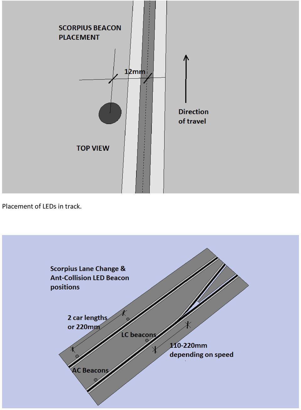
8 LED snap off board. Trim as required to fit your situation. Use only hot glue on plastic tracks for easy removal.

9 Use double sided tape on timber tracks to install. Adding additional LEDs to the Lane Brain. Where cars slide on corners add additional LEDs in series or as shown below. LED board before adding additional LED

10 LED board after adding LEDs and moving earth wire as shown. Delete picture above

11 Delete picture above. Bridging wire are only added if ONE led is to be added. Lane Brain Install tips: 1) Anti-collision Led beacons must be installed if anti-collision box is ticked during configuration. If they have been installed and anti-collision is not required then they must be covered sufficiently enough to stop LED light penetrating. If the car detects an anti-collision beacon and it is not configured to anti-collision mode the operation will be impaired. 2)Use hot glue to attach LED beacon boards to underside of plastic tracks. It removes and cleans up easily. 3)Assemble one LC/LB at a time, fully test in situ before proceeding to the next one. 4)Each LB must be assigned a unique ID. Start/finish line is always 0. Any other lane changer can be assigned any ID from 1-32 in any order. It is common sense however to have the first LC after the start called #1, 2 nd LC, #2 etc. Put a sticker for reference so if you need to re set the ID in future you can easily tell the correct number. 5)Lane Brains must be enclosed for rug racing. Nylon carpet and debris will cause PCB failure. 6)When re-flashing the LB, make sure the laptop is elevated off the floor and not within a metre. This seems to give better results.
Use hot glue to attach LED beacon boards to underside of plastic tracks.")
12 7)Reset button. If pressed put the LB into boot mode, ready to be re-flashed or reconfigured. 8)Each time you re-flash or reconfigure each LB you must turn off the power supply for 5 seconds and back on. This switches it from boot mode into operation mode. 9)Each time the LB goes into boot mode it will start operating any flippers back and forth after 10 seconds. This does 2 things. Firstly it shows it went into boot mode. Secondly it proves if solenoids are working. 10)If the LB power wires are attached and the green LED is not lit it means the polarity is incorrect, or a faulty LB. 11) The antenna wire should be proud or to the side of the PCB and not laying across it. And at right angles if possible. 12) 2 ten connector plugs can be used to separate LC wires to LB wires for a Quick Release set up. 13)When reconfiguring multiple LBs in one go you can leave the switching off/on of the LBs to the end to save turning off on each time. Only downfall here is each LC will click-clack until they are reset to operation mode. This isn t an issue, only noisy! 14)Use vernier callipers to accurately mark out position of LED holes in track and phototransistor hole in car chassis. Use 1mm bit as pilot hole before increasing track LED beacons to 6mm dia. And car chassis to 3mm. De-burr car chassis hole from above before fitting and gluing phototransistor. For very fast track sections increase their hole size to 7-8 mm in diameter to maximise the window of opportunity that the phototransistor has to see the LED in the track as it passes over. The biiger the diameter of the hole the deeper the LED shpuld go. See diagram. 15)Use multimeter to check polarity of wires before and after connection of power wires. 16)Install LEDs flat approx. 4-5mm from the track surface. The dot in the centre of the LED should be the centre of the hole. 17)LEDs should be fixed with double sided tape in a specially routed rebate in the underside of track. It is important the LED is 3-6 mm from the track surface depending on the speed of that particular track section. Reset switch Used in conjunction with reflashing and reconfiguring processes only. Antenna Should be at 90 degrees to PCB if possible. Lane Brain Set up program. See User Manual
If the LB power wires are attached and the green LED is not lit it means the polarity is incorrect, or a faulty LB.")
13 END OF DOCUMENT

Scorpius Installation Guide Version 2.1
 Scorpius Installation Guide Version 2.1 CONTROLLER Install 2 x AAA batteries by removing casing and knob screws. Ensure polarity is correct. Reinstall screws. Battery life approx. 3 months of average use.
R02GA. July 31, 2002. Dear Blue Bird Owner:
 R02GA July 31, 2002 Dear Blue Bird Owner: This notice is sent to you in accordance with the requirements of the National Traffic and Motor Vehicle Safety Act. Blue Bird Body Company has determined that
i ChatterBox! Motorcycle Security
 i Before you Start the Installation * Please read this manual to become familiar with the requirements necessary to complete the installation. * Use a high quality multi-meter to test all wires before
INSTALLATION MANUAL 3RP / 5RP 4-BUTTON SERIES VEHICLE SECURITY SYSTEMS
 3RP / 5RP 4-BUTTON SERIES VEHICLE SECURITY SYSTEMS INSTALLATION MANUAL Before you begin the installation Read the INSTRUCTIONS! Always use a multi-meter when verifying vehicle wiring. Before mounting the
USER MANUAL V5.0 ST100
 GPS Vehicle Tracker USER MANUAL V5.0 ST100 Updated on 15 September 2009-1 - Contents 1 Product Overview 3 2 For Your Safety 3 3 ST100 Parameters 3 4 Getting Started 4 4.1 Hardware and Accessories 4 4.2
PolyBot Board. User's Guide V1.11 9/20/08
 PolyBot Board User's Guide V1.11 9/20/08 PolyBot Board v1.1 16 pin LCD connector 4-pin SPI port (can be used as digital I/O) 10 Analog inputs +5V GND GND JP_PWR 3-pin logic power jumper (short top 2 pins
oxigen system Slot.it oxigen timing RMS installation Dongle driver installation 1/ 11 Race Management Software
 1/ 11 Slot.it oxigen timing RMS installation To install the Slot.it oxigen timing-rms software, follow these steps: 1. download the O2_chrono_installer.zip file from Slot.it ftp site; 2. unzip the downloaded
Document number RS-PRD-00130 Revision 05 Date 20/10/2009 Page 1/30
 Date 20/10/2009 Page 1/30 1. Purpose This document describes the field replacement of the footscan plate cable for these models: 2m hi-end plate SN 11/5/xxx 2m pro plate SN 7/5/xxx 0.5m 2003 hi-end plate
Modifying the Yaesu FT-847 External 22.625 MHz Reference Input
 Modifying the Yaesu FT-847 External 22.625 MHz Reference Input David Smith VK3HZ Introduction This document describes the modification of an FT-847 to allow an external 22.625 MHz Reference oscillator
The $25 Son of a cheap timer This is not suitable for a beginner. You must have soldering skills in order to build this kit.
 The $25 Son of a cheap timer This is not suitable for a beginner. You must have soldering skills in order to build this kit. Micro Wizard has been manufacturing Pinewood Derby timers for over 10 years.
Back-Up Camera Installation Guide
 Hz Hz In This Guide: Back-up camera installation requires connecting power wiring to the existing reverse lighting circuit and adding a chassis ground, as well as routing a video signal cable to the front
1R / 4-BUTTON SERIES
 Button 1 1R / 4-BUTTON SERIES VEHICLE SECURITY SYSTEM Standard Features: Two 4-Button Remote Transmitters Status indicator (LED) Valet / override switch Multi-tone siren Dual stage impact detector Remote
User manual DinaSys DTC/DTS and DTC/DTZ
 PiCommIT has developed the DinaSys DTC/DTS and DinaSys DTC/DTZ turntable controller for the Fleischmann / Marklin Turntables in scale H0, H0m, TT, N and Z. One of the most important starting point was
How to connect to a Class II router using a mobile-phone data cable specifically for Solwise & Safecom routers
 USB to router s serial port How to connect to a Class II router using a mobile-phone data cable specifically for Solwise & Safecom routers by Neo at RouterTech.Org Introduction Routers based on the AR7RD/AR7WRD
Micrio WS1 Replacement Wind Speed Sensor and WC1 Replacement Wind Compass Sensor for Raymarine ST50 and ST60 Wind Instruments. Rev 4.
 Micrio WS1 Replacement Wind Speed Sensor and WC1 Replacement Wind Compass Sensor for Raymarine ST50 and ST60 Wind Instruments. Rev 4.1 The Micrio WS1 Wind Speed Sensor and WC1 Compass Sensor are direct
FG MOISTURE MONITOR Installation & Operation Manual
 FG MOISTURE MONITOR Installation & Operation Manual Issue 3.0 7/20/10 1 Contents SERVICE AND TECHNICAL SUPPORT... 2 INSTALLATION:... 3 MOISTURE SENSOR INSTALLATION:... 3 SENSOR CONNECTOR:... 5 MONITOR
SENSORED BRUSHLESS MOTOR & SPEED CONTROLLER COMBOS
 SENSORED BRUSHLESS MOTOR & SPEED CONTROLLER COMBOS OPERATING INSTRUCTIONS Please keep for future reference Thank you for purchasing this Exceed brushless motor and speed controller combo. We are sure you
UB1 AIR CONDITIONING UNIT INSTALLATION INSTRUCTIONS
 UB1 AIR CONDITIONING UNIT INSTALLATION INSTRUCTIONS INSTALLATION INSTRUCTIONS: Carefully read these instructions before installing your new air-conditioner. AUSTRALIAN AUTOMOTIVE AIR AL00500054E 1 Table
Instruction Manual. 2in1 LAN Tester & Multimeter. Model: LA-1011
 Instruction Manual 2in1 LAN Tester & Multimeter Model: LA-1011 1 Contents Introduction... Features... Safety Precautions.. Meter Description... Electrical Specification... Operation.. AutoRanging Multimeter.
Contractors Guide Central Inverter System Installation
 Contractors Guide Central Inverter System Installation Step By Step Procedures 2,200 Watt/VA 6 Step Installation 1. Mount Bottom Cabinet 2. Mount Top Cabinet 3. Install Batteries 4. Install Conduit 5.
How To Power A Power Control On An Ip40 (Ipl) With A Power Supply (Iplug) With An Ip20 Controller (Iphones) With Power Control (Power Control) With No Antenna) With The Ip20 (Power)
 With A Power Supply (Iplug) With An Ip20 Controller (Iphones) With Power Control (Power Control) With No Antenna) With The Ip20 (Power)") MODEL NUMBER: ISC910-1-0-GB-XX ISC911-5-0-GB-XX IXP20 CONTROLLER SPECIFICATIONS Working Environment Plastic Housing... Power ImproX IXP20 Controller INSTALLATION MANUAL Designed to work in an indoor (dry)
MODEL NUMBER: ISC910-1-0-GB-XX ISC911-5-0-GB-XX IXP20 CONTROLLER SPECIFICATIONS Working Environment Plastic Housing... Power ImproX IXP20 Controller INSTALLATION MANUAL Designed to work in an indoor (dry)
INSTALLATION INSTRUCTIONS
 Rear Vision System Tailgate Handle Camera Mirror Display 2004-2014 Ford F-150 and 2008-2015 Ford Super Duty (Kit part numbers 9002-9521) Kit Contents: Mirror Tailgate Handle with camera and harness Interior
Mazda CX7 2007-09 99-7508
 INSTALLATION INSTRUCTIONS FOR PART 99-7508 APPLICATIONS Mazda CX7 2007-09 99-7508 KIT FEATURES DIN Radio Provision with Pocket ISO Mount Radio Provision with Pocket Double DIN Mount Radio Provision Stacked
with installation dynafact boost GAUGE this manual is for use with systems 64050-64054
 owners manual with installation instructions dynafact boost GAUGE this manual is for use with systems 64050-64054 GENERAL INSTALLATION PRACTICES This manual is an installation guide for all 1. Banks DynaFact
Triac Printed Circuit Board Replacement
 Technical Service Bulletin: Triac Printed Circuit Board Replacement TRONIC 5000C Pro Models: WH17, WH27, WH36 Introduction Fig. 1 ELECTRICITY IS EXTREMELY DANGEROUS. TAKE EXTRA PRECAUTIONS AND ENSURE ALL
SYSTEM 4C. C R H Electronics Design
 SYSTEM 4C C R H Electronics Design SYSTEM 4C All in one modular 4 axis CNC drive board By C R Harding Specifications Main PCB & Input PCB Available with up to 4 Axis X, Y, Z, A outputs. Independent 25
Multi-Protocol decoder 76 200 with Load regulation
 Multi-Protocol decoder 76 2 with Load regulation For locomotives with universal motors on digital layouts operating in the DCC and Motorola data format. Features 76 2 Load regulated multi-protocol decoder
Keep it Simple Timing
 Keep it Simple Timing Support... 1 Introduction... 2 Turn On and Go... 3 Start Clock for Orienteering... 3 Pre Start Clock for Orienteering... 3 Real Time / Finish Clock... 3 Timer Clock... 4 Configuring
Multi Function, User Configurable Remote Vehicle Security System with 4 Button Replaceable Membrane Remote Transmitter
 MODEL PRO-9744 INSTALLATION MANUAL Multi Function, User Configurable Remote Vehicle Security System with 4 Button Replaceable Membrane Remote Transmitter This System Allows The Transmitter Buttons To Be
Recovering from a Hard Drive Failure
 APPENDIXB This appendix describes how to recover from a hard drive failure on a Multiservices Platform Series device. The process for doing so depends on the physical security product that you are using
EtherNet-RS232/485. London Electronics Limited. Ethernet to RS232 or RS485 data converter. Connection details and general information
 London Electronics Limited Warren Court, Chicksands, Shefford, Bedfordshire SG17 5QB Tel +44(0)1462-850967 Fax +44(0)1462-850968 www.london-electronics.com [email protected] Ethernet to RS232
Solar Home System. User Manual. AEH-SHS01-10W2L Solar Home System 2 Lamps
 Solar Home System User Manual AEHSHS0110W2L Solar Home System 2 Lamps All rights reserved Specifications subject to change without prior notice 2 Dear Customer, Thank you for purchasing Schneider Electric
Shunt lock function 3066
 Version: January 2004 Contents Alarm System Activation unit Deactivation unit Digital locking cylinder or Smart Relay 1.0 Method of Operation 4 1.1 General 4 1.2 Turning the Alarm System On 4 1.3 Turning
Networkfleet 3500 Product Line Installation Guide
 Networkfleet 3500 Product Line Installation Guide Light/Medium Duty (L3500) Heavy Duty (H3500) Universal (U3500) www.networkcar.com/fleet Customer Care: (866) 227-7323 [email protected] Table
VOYAGER 570G. 744A Sprayer Control
 VOYAGER 570G 744A Sprayer Control U S E R M A N U A L U S E R M A N U A L Table of Contents CHAPTER 1 - INTRODUCTION...1 SYSTEM CONFIGURATIONS...1 KIT CONTENTS...3 CONTROL HOUSING ASSEMBLY...5 CHAPTER
INSTALLATION MANUAL VEHICLE SECURITY SYSTEM CE-SS200
 INSTALLATION MANUAL VEHICLE SECURITY SYSTEM CE-SS200 FUSION CULTURE TABLE OF CONTENTS There s no point doing something if no one notices. We ve always believed the way to make things happen is by getting
Electronics and Soldering Notes
 Electronics and Soldering Notes The Tools You ll Need While there are literally one hundred tools for soldering, testing, and fixing electronic circuits, you only need a few to make robot. These tools
INSTALLATION INSTRUCTIONS
 INSTALLATION INSTRUCTIONS Accessory Application Publications No. AII 26327 2004 S2000 Issue Date OCT 2004 PARTS LIST Security System: P/N 08E51-S84-100 Attachment Kit: P/N 08E55-S2A-101 2 Remote controls
Time needed: ~3h for lid replacement only. Add 1h for operation harness in lid and ~2h more for installing drive unit and cable harness in trunk.
 DIY for replacing trunk lid and/or retrofitting electrical operation of trunk lid. This document is meant to be a support and give advice on the procedure but I will take no responsibility for any damage
www.sebury.com.cn Digital Keypad Use s Manual
 K3 K4 www.sebury.com.cn Digital Keypad Use s Manual Contents Introduction Introduction Specifications Intramural Interface Circuit 3 Mounting 3 Wiring 5 Power UP 7 Engineer Programming Mode 7 The K3/K4
WARNING! REQUIRED TOOLS & SUPPLIES: HIGH VOLTAGE
 INSTRUCTIONS Product: GEM Electric Motorcars Models: All Subject: Instructions for installing Stereo Accessory Estimated Completion Time:.75 Hours Parts: See Page # 7 REQUIRED TOOLS & SUPPLIES: (1) 3/8
Fitting a Hornby 4 Function Decoder and a PCB Lighting Board to a Hornby Inter City 125 (HST) The lighting board is made by Black Cat Technology
 The lighting board is made by Black Cat Technology") Fitting a Hornby 4 Function Decoder and a PCB Lighting Board to a Hornby Inter City 125 (HST) The lighting board is made by Black Cat Technology All photographs and text are copyright to myself so please
Fitting a Hornby 4 Function Decoder and a PCB Lighting Board to a Hornby Inter City 125 (HST) The lighting board is made by Black Cat Technology All photographs and text are copyright to myself so please
EasyNote TJ Series. Disassembly Manual
 EasyNote TJ Series Disassembly Manual CHAPTER3 Replacing notebook components Preventing static electricity discharge Preparing the work space Required tools Preparing the notebook Adding or replacing memory
AXE114S BINARY CLOCK. revolution Revolution Education Ltd. Email: [email protected] Web: www.rev-ed.co.uk Version 1.1 12/09/08 AXE114.PMD.
 AXE114S BINARY CLOCK Features: The PICAXE binary clock kit tells the time by lighting up blue LEDs in a binary pattern. This is a useful tool for teaching students binary code or simply just confusing/
1 Technical Description Lokal-200PC
 1 Technical Description Lokal-200PC 1.1 Overview laptop with in-built accummulator USB connection correlator box internal power supply laptop (if the device has been supplied by F.A.S.T.) BNC aerial connection
Installation Guide for Hive Active Heating
 Installation Guide for Hive Active Heating Important note: Installation should only ever be carried out by a qualified engineer. Technical Support If you need to contact Hive s Technical Support team during
AudioJoG (TM) Pro 8 Connector PIN LABEL LED Connector PIN LABEL LED. Operations Manual 3.5mm & 6.35mm Mono/Stereo Jacks
 Pro 8 Connector PIN LABEL LED Connector PIN LABEL LED. Operations Manual 3.5mm & 6.35mm Mono/Stereo Jacks") LED/Connector pin identification table AudioJoG (TM) Pro 8 Connector PIN LABEL LED Connector PIN LABEL LED Operations Manual 3.5mm & 6.35mm Mono/Stereo Jacks 3,4,5 pole XLR Male & Female 3,5 & 8 pole 180
LED/Connector pin identification table AudioJoG (TM) Pro 8 Connector PIN LABEL LED Connector PIN LABEL LED Operations Manual 3.5mm & 6.35mm Mono/Stereo Jacks 3,4,5 pole XLR Male & Female 3,5 & 8 pole 180
Targus Wireless RF Mouse USER S GUIDE. Making Your Mobile Life Easier.
 Targus Wireless RF Mouse Visit our Web site at: www.targus.com Features and specifications are subject to change without notice. 2004 Targus Group International and Targus, Inc.. 400-0111-001B USER S GUIDE
Networking. General networking. Networking overview. Common home network configurations. Wired network example. Wireless network examples
 Networking General networking Networking overview A network is a collection of devices such as computers, printers, Ethernet hubs, wireless access points, and routers connected together for communication
Parts and Accessories Installation Instructions
 Parts and Accessories Installation Instructions R5 5 Z CD changer retrofit kit MINI (R 5 and R 53) LHD and RHD The installation time is approx..5 hours, but this may vary depending on the condition of
Bluetooth + USB 16 Servo Controller [RKI-1005 & RKI-1205]
![Bluetooth + USB 16 Servo Controller [RKI-1005 & RKI-1205]](/thumbs/40/21161302.jpg "Bluetooth + USB 16 Servo Controller [RKI-1005 & RKI-1205]") Bluetooth + USB 16 Servo Controller [RKI-1005 & RKI-1205] Users Manual Robokits India [email protected] http://www.robokitsworld.com Page 1 Bluetooth + USB 16 Servo Controller is used to control up to
Bluetooth + USB 16 Servo Controller [RKI-1005 & RKI-1205] Users Manual Robokits India [email protected] http://www.robokitsworld.com Page 1 Bluetooth + USB 16 Servo Controller is used to control up to
MANUAL FOR RX700 LR and NR
 MANUAL FOR RX700 LR and NR 2013, November 11 Revision/ updates Date, updates, and person Revision 1.2 03-12-2013, By Patrick M Affected pages, ETC ALL Content Revision/ updates... 1 Preface... 2 Technical
ILISC515-A Shift Interlock (Manual Lift Door) 2015 Ford Transit, 3.7L and 3.5L
 2015 Ford Transit, 3.7L and 3.5L") An ISO 9001:2008 Registered Company ILISC515-A Shift Interlock (Manual Lift Door) 2015 Ford Transit, 3.7L and 3.5L Introduction The ILISC515-A is a microprocessor driven system for controlling wheelchair
An ISO 9001:2008 Registered Company ILISC515-A Shift Interlock (Manual Lift Door) 2015 Ford Transit, 3.7L and 3.5L Introduction The ILISC515-A is a microprocessor driven system for controlling wheelchair
User Guide Reflow Toaster Oven Controller
 User Guide Reflow Toaster Oven Controller Version 1.5-01/10/12 DROTEK Web shop: www.drotek.fr SOMMAIRE 1. Introduction... 3 2. Preparation of THE REFLOW CONTROLLER... 4 2.1. Power supply... 4 2.2. USB
INSTALLATION GUIDE. Card Reader & Controller with KIM Swipe Reader for Solitaire 850 / 950 / 850L Learnlok PK2930
 INSTALLATION GUIDE Card Reader & Controller with KIM Swipe Reader for Solitaire 850 / 950 / 850L Learnlok PK2930 Card Reader and Controller Model 3.5 with KIM Swipe Reader Table of Contents 1. Features..................................
NOQ_NQ-9121 Z-Wave Data Logger for Gas Meters Firmware Version : 2.55
 NOQ_NQ-9121 Z-Wave Data Logger for Gas Meters Firmware Version : 2.55 Quick Start S This device is a Z-Wave Sensor. Inclusion and Exclusion are confirmed by triple clicking the Z-Wave button on the device.
INSTALLATION INSTRUCTIONS
 Rear Vision System Aftermarket and Factory 5.0, 8.4 and 6.1 MyGig Touch Screen Display (Factory Display requires Chrysler/Dodge dealer to activate) 2009 Current* Dodge Ram (Kit part number 1009-6503) *NOTE:
Clio 2 Pictorial Installation Guide
 Clio 2 Pictorial Installation Guide Fastchip imfd gauge module support for PLX Devices: DM-5 Digital Gauges System Driver - RSTuner VCI and software supplied by: http://www.fastchip.nl Gauges supplied
SYSTEM 45. C R H Electronics Design
 SYSTEM 45 C R H Electronics Design SYSTEM 45 All in one modular 4 axis CNC drive board By C R Harding Specifications Main PCB & Input PCB Available with up to 4 Axis X, Y, Z, & A outputs. Independent 25
LD2 One & Two Zone Water Detection Alarm Installation and Operation Manual
 CMR Electrical Ltd Bolton House Five Chimneys Lane Hadlow Down East Sussex TN22 4DX Tel: 01825 733600 LD2 One & Two Zone Water Detection Alarm Installation and Operation Manual Contents 1) Operation 2)
SE05: Getting Started with Cognex DataMan Bar Code Readers - Hands On Lab Werner Solution Expo April 8 & 9
 SE05: Getting Started with Cognex DataMan Bar Code Readers - Hands On Lab Werner Solution Expo April 8 & 9 Learning Goals: At the end of this lab, the student should have basic familiarity with the DataMan
PUSH BUTTON START INSTALLATION MANUAL
 PUSH BUTTON START INSTALLATION MANUAL ALTHOUGH THIS PRODUCT HAS BEEN THOROUGHLY TESTED KPIERSON TECHNOLOGIES ASSUMES NO RESPONSIBILITY FOR ANY DAMAGE THAT MAY RESULT BY THE INSTALLATION OF THIS PRODUCT.
Assembly Instructions: Shortwave Radio Kit
 Assembly Instructions: Shortwave Radio Kit MTM Scientific, Inc P.O. Box 522 Clinton, MI 49236 U.S.A Introduction Fig 1: The assembled Shortwave Radio Kit The SHORTWAVE RADIO KIT (#SWRAD) from MTM Scientific
Alfa Romeo 147 On board instruments installation guide
 Alfa Romeo 147 On board instruments installation guide Alfa Romeo 147 On board instruments installation guide This guide is describing how I installed oil temperature and oil pressure gauges to my Alfa
General Tips for Installation of mobridge into Porsche Vehicles
 General Tips for Installation of mobridge into Porsche Vehicles Disclaimer: the information herein is provided as a convenient as-is reference only. The information herein is not guaranteed to be accurate
RC2200DK Demonstration Kit User Manual
 Demonstration Kit User Manual Table of contents TABLE OF CONTENTS... 1 QUICK INTRODUCTION... 2 INTRODUCTION... 3 DEMONSTRATION BOARD... 4 POWER SUPPLY SECTION... 5 RS-232 INTERFACE... 6 CONNECTORS... 7
BUILDING INSTRUCTIONS
 etap2hw 38 mm I2C to LCD Interface BUILDING INSTRUCTIONS October 2013 P. Verbruggen Rev 1.01 15-Oct-13 Page 1 Table of Contents Chapter 1 General Information 1.1 ESD Precautions 1.2 Further Supplies 1.3
RS232/DB9 An RS232 to TTL Level Converter
 RS232/DB9 An RS232 to TTL Level Converter The RS232/DB9 is designed to convert TTL level signals into RS232 level signals. This cable allows you to connect a TTL level device, such as the serial port on
INSTALLATION GUIDE OWNER S GUIDE
 INSTALLATION GUIDE OWNER S GUIDE KEYLESS ENTRY MODELS KE100 / KE150 / 1702 CONTENTS System Features... 1 System Components... 1 Technical Assistance... 1 Before You Begin... 1 Precautions... 1-2 Making
USER S MANUAL TACHOTERMINAL PRO. Firmware 2.00.191
 USER S MANUAL TACHOTERMINAL PRO Firmware 2.00.191 In the Box miniusb-usb cable (1.8 metres) 2GB removable memory card (in the slot) TTConfigurator (pre-installed in TERMINAL folder) Optional Accessories
FTDI VCP DRIVER (free) (WIN/MAC/LINUX) http://www.ftdichip.com/drivers/vcp.htm
 (WIN/MAC/LINUX) http://www.ftdichip.com/drivers/vcp.htm") 002 - CONNECTING THE PRINTER Now that you have an idea what 3D printing entails, we can continue and connect the printer to your computer. First make sure you have a computer with a decent amount of RAM
002 - CONNECTING THE PRINTER Now that you have an idea what 3D printing entails, we can continue and connect the printer to your computer. First make sure you have a computer with a decent amount of RAM
MTH SD70ACe DCC Ready Soundtraxx AT-1000 EMD 710 Sound Decoder Install Revised June 1, 2011
 303 447-9251 Fax: 303 447-1406 [email protected] Introduction MTH SD70ACe DCC Ready Soundtraxx AT-1000 EMD 710 Sound Decoder Install Revised June 1, 2011 The MTH DCC Ready SD70ACe has very little
Neo-Neon. LED Vision Mesh Screen Operation Manual. LED Vision Mesh Screen. Neo-Neon International Ltd He Shan Decorative Lighting Company Limited
 Neo-Neon LED Vision Mesh Screen Operation Manual He Shan Decorative Lighting Company Limited LED Display Engineering Department 1 Contents Chapter1 Specification and Function Parameters 3 Chapeter2 Structure
430 Power/Electronics Replacement
 Replacing the main board WARNING Before proceeding, turn off the main power switch and unplug the power cord. Caution Make sure you are properly grounded with an ESD strap before continuing. The main printed
tidesmarine Smart Seal Temperature Alarm System Generation II Installation Instructions Starboard side cable
 tidesmarine Smart Seal Temperature Alarm System Generation II Installation Instructions Starboard side cable Port side cable (with black cable tie attached) Power cable Preparing for Installation 1 Overall
Installation Instructions. Thermo Call TC3
 Installation Instructions Thermo Call TC3 1 2 # 24990A 965 082 AMP 3 4 # 98393A # 67769A sw Improper installation or repair of Webasto heating and cooling systems can cause fire or the leakage of deadly
CMC-DN01 DeviceNet Slave Communication Card Operation Manual
 CMC-DN01 DeviceNet Slave Communication Card Operation Manual 2011-12-26-A Warning This operation manual provides introduction on the functions, specifications, installation, basic operation and settings
SMS Alarm. User Manual
 SMS Alarm User Manual 1 1. Introduction... 2 2. SMSA1000 Specifications... 3 3. Parts Identifications... 4 4. Packing Contents... 5 5. Battery and SIM Card Installation... 6 5.1 Open the Back Cover...
Contents. Document information
 User Manual Contents Document information... 2 Introduction... 3 Warnings... 3 Manufacturer... 3 Description... Installation... Configuration... Troubleshooting...11 Technical data...12 Device Scope: PCB
Wireless Home Security Alarm System AM 500
 Wireless Home Security Alarm System AM 500 12 MONTH GUARANTEE Installation & Operating Instructions INTRODUCTION The AM500 is a simple self-contained alarm system. It protects the home by sounding a siren
DIY Y6. Build Manual V.A 2014
 DIY Y6 Build Manual V.A 2014 1 Contents Thanks for purchasing a DIY Y6! These instructions will show you how to assemble a Y6 using the Pixhawk autopilot system and ArduCopter/APM:Copter firmware. If you
INSTRUCTION MANUAL All-In-One GSM Home Alarm System SB-SP7200-GSM
 INSTRUCTION MANUAL All-In-One GSM Home Alarm System SB-SP7200-GSM Revised: August 28, 2014 PRODUCT REFERENCE MOUNTING ACCESSORIES PIR / MOTION DETECTION UNIT MAIN UNIT POWER ADAPTER MOUNTING ACCESSORIES
DN1600 MEGA SPIN Installation Guide INNOVATIVE CONCEPTS IN ENTERTAINMENT INC. 10123 MAIN STREET, CLARENCE, NY 14031 SERVICE: 1-716-759-0360 FAX:
 DN600 MEGA SPIN Installation Guide INNOVATIVE CONCEPTS IN ENTERTAINMENT INC. 0 MAIN STREET, CLARENCE, NY 40 SERVICE: -76-759-060 FAX: -76-759-0884 EMAIL: [email protected] WEBSITE: www.icegame.com Your
4.3-inch Back-Up Camera
 TM 4.-inch Back-Up Camera Model No.: PKC0BU4 Owner s Manual and Warranty Information Read these instructions completely before using this product. Retain this Owner s Manual for future reference. INTRODUCTION
Juice Box Stages 1&2 135&335 Installation Guide 5/10/08
 Tools Required: 8mm socket or nut driver Small flat head screwdriver Electrical tape, masking tape, or shrink tube Pep talk: Although the install looks daunting at first, once you get the learning curve
BMD16N-SD. version 1.2
 BMD16NSD version 1.2 Feedback decoder with 16 contacts with integrated current detection for the S88bus Compatible with a.o. Märklin Digital, Uhlenbrock Intellibox, Fleischmann TwinCenter and LDT HSI88
ELECTRONIC THERMOSTAT AND THERMOMETER With SPEED CONTROL
 148 OLD CONCORD TURNPIKE, BARRINGTON NH 03825 USA TEL (603) 868-5720 FAX (603) 868-1040 1-800-435-6708 E-Mail:[email protected] www.seafrost.com ELECTRONIC THERMOSTAT AND THERMOMETER With SPEED CONTROL
Mirror Mount Video Monitor/Recorder with Front and Rear View Night Cameras PLCMDVR5
 Mirror Mount Video Monitor/Recorder with Front and Rear View Night Cameras PLCMDVR5 www.pyleaudio.com Instruction Manual Installation and Connection: 1. Please disconnect your car battery. 2. In the contents
Elecraft K3 KPA3 Power Connector Replacement Revision A Review, April 16, 2012 Copyright 2012, Elecraft, Inc. All Rights Reserved
 Introduction Elecraft K3 KPA3 Power Connector Replacement Revision A Review, April 16, 2012 Copyright 2012, Elecraft, Inc. All Rights Reserved The connectors furnishing high current to the KPA3 module
SCREENLOGIC INTERFACE WIRELESS CONNECTION KIT
 SCREENLOGIC INTERFACE WIRELESS CONNECTION KIT FOR INTELLITOUCH AND EASYTOUCH CONTROL SYSTEMS INSTALLATION GUIDE IMPORTANT SAFETY INSTRUCTIONS READ AND FOLLOW ALL INSTRUCTIONS SAVE THESE INSTRUCTIONS Technical
Installation Instructions. ThermoCall TC4. Entry/Advanced
 Installation Instructions ThermoCall TC4 Entry/Advanced Thermo Call TC4 1 2 # 24990A 965 082 AMP 3 4 # 98393A # 67769A Thermo Call TC4 5 ThermoCall TC4 Entry 1 2 3 4 5 6 7 8 9 10 11 12 sw Please refer
WAMLocal. Wireless Asset Monitoring - Local Food Safety Software. Software Installation and User Guide BA/WAM-L-F
 Wireless Asset Monitoring - Local Food Safety Software BA/WAM-L-F Software Installation and User Guide System Overview The BAPI Wireless Asset Monitoring Local (WAM Local) Software receives temperature
Drive Doctor for Nintendo Wii
 Drive Doctor for Nintendo Wii Installation Guide. Warning: Installation of Drive Doctor for Nintendo Wii requires you to have some prior experience of soldering, and demands careful following of these
KVT-729DVD INSTALLATION MANUAL
 MONITOR WITH DVD RECEIVER KVT-729DVD INSTALLATION MANUAL B54-4516-00/00 (EV) Accessories 1 0...1...1 2!...1...2 3...1 4 5...1...1 6...2 7...4 8...4 9...2 2 KVT-729DVD Installation Procedure 1. To prevent
INSTALLATION INSTRUCTIONS
 INSTALLATION INSTRUCTIONS Accessory Application Publications No. AII23628 2003 PILOT Issue Date MAY 2002 PARTS LIST Security System Kit (sold separately): P/N 08E51-S84-100 2 Remote controls Attachment
Control Box Wiring For PRSstandard Tool
 888-680-4466 ShopBotTools.com Control Box Wiring For PRSstandard Tool Copyright 2016 ShopBot Tools, Inc. page 1 Copyright 2016 ShopBot Tools, Inc. page 2 Table of Contents Introduction:...5 Installation:...5
Total solder points: 167 Difficulty level: beginner 1 2 3 4 5 advanced DMX CONTROLLED RELAY K8072 ILLUSTRATED ASSEMBLY MANUAL
 Total solder points: 167 Difficulty level: beginner 1 2 3 4 5 advanced DMX CONTROLLED RELAY K8072 Control a relay by means of the wellknown DMX512 protocol. ILLUSTRATED ASSEMBLY MANUAL H8072IP-1 Features
POCKET AUDIO GENERATOR K8065
 POCKET AUDIO GENERATOR K8065 Great little gadget for service repair, testing, education, etc... ILLUSTRATED ASSEMBLY MANUAL H8065IP-1 VELLEMAN NV Legen Heirweg 33 9890 Gavere Belgium Europe www.velleman.be
Firewall Cover Installation Instruction Sheet
 Firewall Cover Installation Instruction Sheet Please Read Carefully Our Firewall cover is designed to fit on the stock strut brace. If you have an aftermarket strut brace than it is you re responsibility