Rock Bolt Condition Monitoring Using Ultrasonic Guided Waves
|
|
|
- Luke Randall Montgomery
- 10 years ago
- Views:
Transcription
1 Rock Bolt Condition Monitoring Using Ultrasonic Guided Waves Bennie Buys Department of Mechanical and Aeronautical Engineering University of Pretoria

2 Introduction Rock Bolts and their associated problems Available Integrity Testing Methods Guided Ultrasonic Waves Experimental Setup Early investigations Simulating and testing 2 mayor defects Conclusion and recommendations Voltage (mv) Gaussian windowed sine burst excitation. Excitation and reception are on the same end of the bolt Recovery time of circuit L(,1) First end reflection F(1,1) First end reflection L(,1) Second end reflection Time (ms)
 First end reflection F(1,1) First")
3 Scope of work Investigation into rock bolts and their associated defects and available NDT testing methods. Developing a fundamental understanding of ultrasonic waves and FEA modelling of wave propagation. Simulating an unbounded rock bolt using Finite Elements and comparing it to analytical wave equation results. Comparing the Experimental unbounded bolt to the FEA model.

4 Scope of work Perfectly embedded bolts - FEA model - Experimental bolt Simulating two mayor resin anchored rock bolts - Partially embedded bolts - Local corrosion defects

5 Rock Bolts and their associated Problems Rockbolts - steel bolts fixed into the roof to prevent the movement and expansion of rock strata in mines. 187 ground fall accidents were reported in 26 with 85 people killed in these accidents.

6 The Resin Anchored Bolt Different types of rock bolts in used. This study focussed on resin anchored rock bolts. More than 16 million rock bolts are installed each year. Of these 45 percent is resin anchored bolts. 5 % of the resin bolts installed not effective. Two component cartridges containing resin and catalyst. Bolt rod spun into the resin cartridges by the drill.

7 The Resin Anchored Bolt Different problems with resin anchored rock bolts: Incomplete mixing Overspinning Corrosion Voids Cracks All result in a unsatisfactory bond and/or reduction of the integrity of the roof support.

8 Rock Bolt s Integrity Testing A few approaches are presently used for measuring integrity. Pull-Out Test: Most frequently used in the SA mines. Very expensive and destructive. GRANIT (Scotland): Resultant vibrational response interpreted by neural networks. It is the only nondestructive patent on the market Very expensive and can only be used on bolts that was monitored when it was installed. Boltometer (Sweden): Ultrasonic device, in used since Can indicate bad grouting, but if the impedances of the grout and surrounding rock are the same, wave energy will dissipate into the rock before it could reach a major defect, signaling good grouting. Imperial College (UK): Pulse echo test using guided ultrasonic waves.
: Ultrasonic device, in used since 1979.")
9 Rock Bolt s Integrity Testing Ultrasonic Guided Waves: Principle: A short duration Gaussian windowed sine burst is used to excite a guided wave in the bolt from the free end. The wave is then reflected from the other end and from any major defects. From the reflection arrival time and knowledge of the wave velocity dispersion curves, the positions of the defects or the bolt length can be calculated.

10 Rock Bolt s Integrity Testing Ultrasonic Guided Waves: The quality of the grouting and the location of the defect can be determined. Specific modes can be selected that are less sensitive to differences in impedance compared to the Boltometer. Present study extends the previous work to investigate damage in more realistic embedded bolts which deviate from pure cylinders.

11 Ultrasonic Guided Waves What is guided waves? Ultrasonic waves that propagate in solid media with boundaries. These ultrasonic waves experience reflection and refraction with the boundary of the solid, which cause mode conversion between longitudinal and shear waves. Different guided wave modes can exist in a cylindrical solid (Rock Bolt). Each of these modes has a particular wave structure. The wave structure describes the distribution of particle motion in the cylindrical solid. Some modes have large particle motion amplitudes near the surface, while others feature more intense motion near the middle of the cylinder. The wave structure determines the sensitivity of the particular mode to a particular flaw type.

12 Ultrasonic Guided Waves The velocity of propagating waves is one of the most important parameters in ultrasonic testing. In bulk waves it is constant and can be calculated with the well known equation: c 2 = E/p, but in guided waves it changes with frequency and this relationship is represented on a dispersion curve.

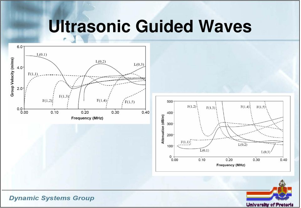
13 Ultrasonic Guided Waves Dispersion curves are used to describe and predict the relationship between frequency, phase velocity and group velocity, mode and thickness. An example of the phase and group velocity curves for a 2 mm diameter perfectly elastic rod in a vacuum is shown in the following slide:

14 Ultrasonic Guided Waves
15 FEA Modelling of guided waves Axisymmetrical models. Assuming axial symmetry of the geometry, load, boundary conditions and materials, allows one to analyze the three dimensional bolt and surrounding rock mass with a two dimensional model. Full three dimensional models. Defects can occur that are not symmetric around the axis and in which case a three dimensional model of the rock bolt will be necessary. Software. The MSC.Software package, comprising MSC.Patran, MSC.Nastran and MSC.Dytran Computer Capabilities. 3.2 GHz Pentium 4 computer and 3 GB of RAM.

16 FEA Modelling of guided waves The effect of mesh density and time step size: The time step size is more critical than the element size for the implicit solver The element size is more critical than the time step size for the explicit solver.

17 FEA Modelling of guided waves Infinite boundary? Unsolvable FEA model? The finite boundary of the rock mass of the FE model causes the leaking waves to be reflected and superimposed on the progressing waves in the bolt. Solutions: Energy absorbing elements at the boundaries. Move the boundary a large distance away from the bolt so that the boundary does not influence the results. This however causes the model to become very large and consequently time-consuming to solve, limiting the present study to the low frequency scenario. Maybe with a new generation of computers it will also become practically feasible to model the high frequency scenario.

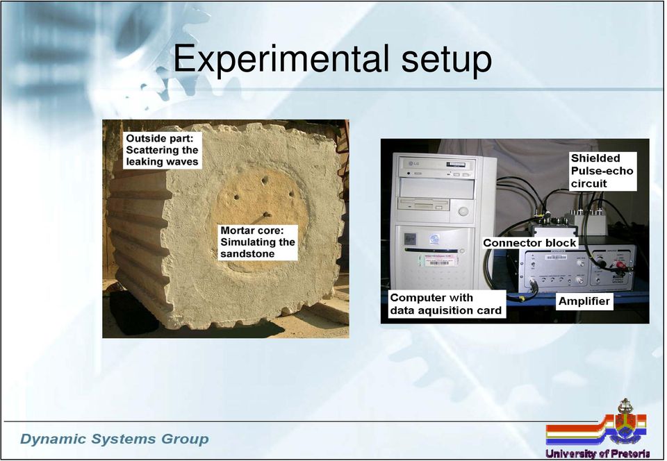
18 Experimental setup
19 Experimental setup Exciting a specific guided wave mode. Signal with a large number of cycles. - Conceal early reflections. 1 5 khz Gaussian Toneburst Gaussian Windowed sine burst. The Gaussian window allows more energy to be focussed at a particular frequency. Amplitude Time (s) x FFT of Gaussian Toneburst.2 Amplitude Frequency (khz)
 x 1-4.25 FFT of Gaussian Toneburst.2 Amplitude.15.1.5 2 25 3 35 4 45 5 55 6 65 7 75 8 Frequency (khz)")
20 Experimental setup Exciting a specific guided wave mode. Displacement of the transducer should match the displacement of the mode profile. Piezo ceramic transducer. Disc that was cut with thin blades into small blocks. These blocks can be individually controlled to excite different mode shapes.

21 Early Investigations Experimental Unbounded rock bolt A 1.5 m long mild steel bolt, with a diameter of 2 mm was suspended in the air on strings to.25 Gaussian windowed sine burst exitation with amplitude of 2 V Clipped at.2 V represent an unbounded.2 configuration Recovery time of pulse-echo circuit Voltage (V) L(,1) First end reflection F(1,1) First end reflection L(,1) Second end reflection Time (ms)
22 Early Investigations Comparison Experimental and FEA
23 Early Investigations Group Velocity Comparison 52 5 FEM EXPERIMENTAL POCHHAMMER-CHREE 48 Group Velocity (m/s) L(,1) Frequency (khz)
24 Perfectly Embedded Bolt Perfectly Embedded bolt 4 khz 1 Experimental 4 khz Voltage (mv) Displacement (μm) Time (ms) Recovery time of circuit Gaussian windowed sine burst excitation FEM 4 khz Result of no damping First end reflection First end reflection Gaussian windowed sine burst excitation Time (ms)
25 Perfectly Embedded Bolt Perfectly Embedded bolt 5 khz 1 Experimental 5 khz Voltage (mv) Displacement (μm) Recovery time of circuit Gaussian windowed sine burst excitation Time (ms) FEM 5 khz Result of no damping Gaussian windowed sine burst exitation Time (ms) First end reflection First end reflection
26 Perfectly Embedded Bolt Perfectly Embedded bolt 6 khz 1 Experimental 6 khz First end reflection Voltage (mv) 5-5 Reverberations Gaussian windowed tone burst excitation Time (ms) Displacement (μm).5.25 FEM 6 khz First end reflection Result of no damping -.25 Gaussian windowed tone burst excitation Time (ms)
27 Defect - Partially Encapsulated bolt Model of the Partially Encapsulated Bolt
28 Defect - Partially Encapsulated bolt Results - 5 khz Voltage (mv) Displacement (μm) Displacement (μm) khz Gaussian windowed sine burst excitation khz Gaussian windowed sine burst excitation Recovery time of circuit (a) Experimental Bolt Reflection from start of encapsulation (b) Axisymmetric Model Reflection from start of encapsulation (c) 3 Dimensional Model 5 khz Gaussian windowed sine burst excitation Reflection from start of encapsulation Time (ms) First end reflection First end reflection First end reflection
29 Defect - Partially Encapsulated bolt Results - 6 khz Voltage (mv) Displacement (μm) Displacement (μm) khz Gaussian windowed sine burst excitation (a) Experimental bolt Ringing of transducer (b) 6 khz Gaussian windowed sine burst excitation Reflection from start of encapsulation Axisymmetric model Reflection from start of encapsulation (c) 3 dimensional model 6 khz Gaussian windowed sine burst excitation Reflection from start of encapsulation First end reflection First end reflection Time (ms)
30 Defect - Partially Encapsulated bolt Concluding Remarks Partially encapsulated bolts. The three dimensional model the reflected signal becomes stretched out in time for the higher frequencies. At higher frequencies the velocity of the pulse in the concrete causes earlier reflections from the boundary of the mortar block. These reflections interfere with the reflection from the start of the encapsulation, causing the stretched signal. For the higher frequency excitations the reflections from the start of the encapsulation are smaller than the bolt end reflections. This illustrates that more energy propagates in the centre of the bolt at higher frequencies and more energy propagates near the bolt surface at lower frequencies. The start of the encapsulation are much smaller for the experimental bolt. An explanation is that for the experimental bolt more energy is dissipated due to leakage which could not be exactly modelled by the FE models due to uncertainties of the material properties. From the above results it is concluded that the signal is not significantly influenced by resin defects when the frequency of the signal is high, because the energy propagates more in the centre of the bolt.
31 Defect Local corrosion cracking Model of the Corrosion cracking
32 Defect Local corrosion cracking Results 1 (a) Reflection from crack First end reflection Displacement (μm) (b) Reflection from crack First end reflection Reflection from crack in bolt Reflection from crack in mortar (c) 1 First end reflection Time (ms)
33 Defect Local corrosion cracking Concluding Remarks Local corrosion cracking. It is possible to detect simulated local corrosion cracks with the finite element models. Clear reflections for the crack in the bolt can be seen. If the bolt, resin and rock are cracked, different reflections are observed. These different reflections complicate the interpretation of the results. Overlapping of returning signals can also add to complicate the interpretation of the results. It is therefore recommended that more sophisticated signal processing techniques be utilized for future studies.
34 Conclusion and Recommendations Guided ultrasonic waves testing seems to hold promise as a testing method, as comparable results could be obtained from experimental and finite element models considered in this study. Unbounded bolt Axisymmetrical model compares well with the experimental bolt. The group velocity curves of these models compared well with the Pochammer-Chree frequency equation group velocity curve for a rod in air. Partially encapsulated bolt. The FE model of this bolt compares well to the experimental results. At high frequencies the energy propagates more along the centre of the bolt. It is recommended to use lower frequencies when defects such as these need to be identified.
35 Conclusion and Recommendations Local corrosion cracking. It is possible to detect these simulated local corrosion cracks with the finite element models. Clear reflections from the crack in the bolt can be seen. If the bolt, resin and rock are all cracked, different reflections are observed. This complicates the interpretation of results. It is recommended that signal processing techniques be investigated in future studies. Further investigations should consider other scenarios such as inclined and multiple crack scenarios.
36 Conclusion and Recommendations This study considered only the time of arrival to locate the simulated defects. However, the amplitude of the reflecting signal may also contain information on the nature and location of a defect. Effect of damping as well as the effect of transducer mounting on the observed responses. Considering higher frequencies - higher frequency modes are less sensitive to material properties, epoxy thickness and surface defects. Obtain a reliable indication of the bolt's length. Basic principles and concepts developed here could soon be extended to higher frequencies with a new generation of computers or by applying energy absorbing boundaries.
37 Acknowledgements Professor Stephan Heyns for his excellent guidance with the project. Dr. Phillip Loveday for his expert help and guidance with the project. All the staff of the Sasol Laborotory for Structural Mechanics I also gratefully acknowledge the financial support of the Mine Health and Safety Council in the execution of this research.
DESIGN AND EVALUATION OF PROBE WITH THREE DEGREE- OF-FREEDOM FOR NON-DESTRUCTIVE TEST USING THREE- DIMENSIONAL FINITE ELEMENT METHOD
 DESIGN AND EVALUATION OF PROBE WITH THREE DEGREE- OF-FREEDOM FOR NON-DESTRUCTIVE TEST USING THREE- DIMENSIONAL FINITE ELEMENT METHOD Masafumi Aoyanagi Graduate School of Systems and Information Engineering,
3-D WAVEGUIDE MODELING AND SIMULATION USING SBFEM
 3-D WAVEGUIDE MODELING AND SIMULATION USING SBFEM Fabian Krome, Hauke Gravenkamp BAM Federal Institute for Materials Research and Testing, Unter den Eichen 87, 12205 Berlin, Germany email: [email protected]
CHAPTER 4 4 NUMERICAL ANALYSIS
 41 CHAPTER 4 4 NUMERICAL ANALYSIS Simulation is a powerful tool that engineers use to predict the result of a phenomenon or to simulate the working situation in which a part or machine will perform in
A wave lab inside a coaxial cable
 INSTITUTE OF PHYSICS PUBLISHING Eur. J. Phys. 25 (2004) 581 591 EUROPEAN JOURNAL OF PHYSICS PII: S0143-0807(04)76273-X A wave lab inside a coaxial cable JoãoMSerra,MiguelCBrito,JMaiaAlves and A M Vallera
APPLICATION NOTE AP050830
 APPLICATION NOTE AP050830 Selection and use of Ultrasonic Ceramic Transducers Pro-Wave Electronics Corp. E-mail: [email protected] URL: http://www.prowave.com.tw The purpose of this application note
Finite Element Analysis for Acoustic Behavior of a Refrigeration Compressor
 Finite Element Analysis for Acoustic Behavior of a Refrigeration Compressor Swapan Kumar Nandi Tata Consultancy Services GEDC, 185 LR, Chennai 600086, India Abstract When structures in contact with a fluid
Plate waves in phononic crystals slabs
 Acoustics 8 Paris Plate waves in phononic crystals slabs J.-J. Chen and B. Bonello CNRS and Paris VI University, INSP - 14 rue de Lourmel, 7515 Paris, France [email protected] 41 Acoustics 8 Paris We
Dynamics-based Structural Health Monitoring Using Laser Vibrometry
 Dynamics-based Structural Health Monitoring Using Laser Vibrometry Massimo Ruzzene Atlanta, GA - USA Politecnico di Millano 05/23/2007-1- Outline Introduction to dynamics-based SHM Laser Vibrometry Our
Fluid structure interaction of a vibrating circular plate in a bounded fluid volume: simulation and experiment
 Fluid Structure Interaction VI 3 Fluid structure interaction of a vibrating circular plate in a bounded fluid volume: simulation and experiment J. Hengstler & J. Dual Department of Mechanical and Process
Impact Echo Scanning Technology for Internal Grout Condition Evaluation in Post-Tensioned Bridge Ducts
 Impact Echo Scanning Technology for Internal Grout Condition Evaluation in Post-Tensioned Bridge Ducts Yajai Tinkey, Ph.D. Olson Engineering, Wheat Ridge, Colorado Larry D. Olson, P.E. Olson Engineering,
Dispersion diagrams of a water-loaded cylindrical shell obtained from the structural and acoustic responses of the sensor array along the shell
 Dispersion diagrams of a water-loaded cylindrical shell obtained from the structural and acoustic responses of the sensor array along the shell B.K. Jung ; J. Ryue ; C.S. Hong 3 ; W.B. Jeong ; K.K. Shin
Advancements in High Frequency, High Resolution Acoustic Micro Imaging for Thin Silicon Applications
 Advancements in High Frequency, High Resolution Acoustic Micro Imaging for Thin Silicon Applications Janet E. Semmens Sonoscan, Inc. 2149 E. Pratt Boulevard Elk Grove Village, IL 60007 USA Phone: (847)
APPLICATION NOTE ULTRASONIC CERAMIC TRANSDUCERS
 APPLICATION NOTE ULTRASONIC CERAMIC TRANSDUCERS Selection and use of Ultrasonic Ceramic Transducers The purpose of this application note is to aid the user in the selection and application of the Ultrasonic
Scanning Acoustic Microscopy Training
 Scanning Acoustic Microscopy Training This presentation and images are copyrighted by Sonix, Inc. They may not be copied, reproduced, modified, published, uploaded, posted, transmitted, or distributed
Ultrasonic Wave Propagation Review
 Ultrasonic Wave Propagation Review Presented by: Sami El-Ali 1 1. Introduction Ultrasonic refers to any study or application of sound waves that are higher frequency than the human audible range. Ultrasonic
Long Range Guided Wave Inspection Usage Current Commercial Capabilities and Research Directions
 Long Range Guided Wave Inspection Usage Current Commercial Capabilities and Research Directions M.J.S. Lowe and P. Cawley Department of Mechanical Engineering Imperial College London 29 March 2006 Summary
METHOD OF STATEMENT FOR STATIC LOADING TEST
 Compression Test, METHOD OF STATEMENT FOR STATIC LOADING TEST Tension Test and Lateral Test According to the American Standards ASTM D1143 07, ASTM D3689 07, ASTM D3966 07 and Euro Codes EC7 Table of Contents
Numerical Analysis of Independent Wire Strand Core (IWSC) Wire Rope
 Wire Rope") Numerical Analysis of Independent Wire Strand Core (IWSC) Wire Rope Rakesh Sidharthan 1 Gnanavel B K 2 Assistant professor Mechanical, Department Professor, Mechanical Department, Gojan engineering college,
Numerical Analysis of Independent Wire Strand Core (IWSC) Wire Rope Rakesh Sidharthan 1 Gnanavel B K 2 Assistant professor Mechanical, Department Professor, Mechanical Department, Gojan engineering college,
SIESMIC SLOSHING IN CYLINDRICAL TANKS WITH FLEXIBLE BAFFLES
 SIESMIC SLOSHING IN CYLINDRICAL TANKS WITH FLEXIBLE BAFFLES Kayahan AKGUL 1, Yasin M. FAHJAN 2, Zuhal OZDEMIR 3 and Mhamed SOULI 4 ABSTRACT Sloshing has been one of the major concerns for engineers in
Introduction to acoustic imaging
 Introduction to acoustic imaging Contents 1 Propagation of acoustic waves 3 1.1 Wave types.......................................... 3 1.2 Mathematical formulation.................................. 4 1.3
PIPELINE INSPECTION UTILIZING ULTRASOUND TECHNOLOGY: ON THE ISSUE OF RESOLUTION By, M. Beller, NDT Systems & Services AG, Stutensee, Germany
 ABSTRACT: PIPELINE INSPECTION UTILIZING ULTRASOUND TECHNOLOGY: ON THE ISSUE OF RESOLUTION By, M. Beller, NDT Systems & Services AG, Stutensee, Germany Today, in-line inspection tools are used routinely
Physics 9e/Cutnell. correlated to the. College Board AP Physics 1 Course Objectives
 Physics 9e/Cutnell correlated to the College Board AP Physics 1 Course Objectives Big Idea 1: Objects and systems have properties such as mass and charge. Systems may have internal structure. Enduring
REHABILITATION OF THE FIGUEIRA DA FOZ BRIDGE
 REHABILITATION OF THE FIGUEIRA DA FOZ BRIDGE A.Rito Proponte, Lda, Lisbon, Portugal J. Appleton A2P Consult, Lda, Lisbon, Portugal ABSTRACT: The Figueira da Foz Bridge includes a 405 m long cable stayed
Hunting Bats. Diagnostic Ultrasound. Ultrasound Real-time modality
 Diagnostik Ultrasound Basic physics, image reconstruction and signal processing Per Åke Olofsson Dpt of Biomedical Engineering, Malmö University Hospital, Sweden Ultrasound Real-time modality 17-WEEK FETAL
Active and passive structural health monitoring system based on arrays of ultrasonic guided waves transducers
 DINFO Dipartimento di Ingegneria dell Informazione Department of Information Engineering Active and passive structural health monitoring system based on arrays of ultrasonic guided waves transducers L.
Efficient implementation of Full Matrix Capture in real time ultrasonic damage imaging
 Efficient implementation of Full Matrix Capture in real time ultrasonic damage imaging Patrice Masson, Nicolas Quaegebeur, Pierre Claude Ostiguy GAUS, Mechanical Engineering Dept. Université de Sherbrooke
Measuring the Condition of Prestressed Concrete Cylinder Pipe
 Measuring the Condition of Prestressed Concrete Cylinder Pipe John Marshall, P.E.I, I J.W. Marshall and Associates, and Paul S. Fisk, President NDT Corporation Introduction Prestressed Concrete Cylinder
Piezoelectric Driven Non-toxic Injector for Automated Cell Manipulation
 Medicine Meets Virtual Reality 18 J.D. Westwood et al. (Eds.) IOS Press, 2011 2011 The authors. All rights reserved. doi:10.3233/978-1-60750-706-2-231 231 Piezoelectric Driven Non-toxic Injector for Automated
Burst Pressure Prediction of Pressure Vessel using FEA
 Burst Pressure Prediction of Pressure Vessel using FEA Nidhi Dwivedi, Research Scholar (G.E.C, Jabalpur, M.P), Veerendra Kumar Principal (G.E.C, Jabalpur, M.P) Abstract The main objective of this paper
Safakcan Tuncdemir 1, William M. Bradley *2. 1. Introduction
 Modeling and Experimental Verification of the Power Transfer and Thermal Characteristics of Piezoelectric Transformers Subjected to Combined Mechanical and Electrical Loading Safakcan Tuncdemir 1, William
Acoustic GHz-Microscopy: Potential, Challenges and Applications
 Acoustic GHz-Microscopy: Potential, Challenges and Applications A Joint Development of PVA TePLa Analytical Systems GmbH and Fraunhofer IWM-Halle Dr. Sebastian Brand (Ph.D.) Fraunhofer CAM Fraunhofer Institute
Gage Applied Technologies
 Copyright 2004 As seen in Evaluation Engineering/September 2004 1 Use of a PC-Based Digitizer in an Ultrasonic Flaw-Detection System Written by: Andrew Dawson, Ph.D. ABSTRACT: Use of modern high-speed
NON-DESTRUCTIVE METHODS. CE 165: Concrete Materials and Concrete Construction
 NON-DESTRUCTIVE METHODS NON-DESTRUCTIVE METHODS Purpose: quick assessment of the structure Non-Destructive Techniques Many industrialized nations currently dedicate a considerable portion of the construction
Part IV. Conclusions
 Part IV Conclusions 189 Chapter 9 Conclusions and Future Work CFD studies of premixed laminar and turbulent combustion dynamics have been conducted. These studies were aimed at explaining physical phenomena
Mounting instructions. Acceleration Transducer B12. B 26.B12.10 en
 Mounting instructions Acceleration Transducer B12 B 26.B12.10 en B12 3 Contents Page Safety instructions.............................................. 4 1 Scope of supply..............................................
ACOUSTIC EMISSION SIGNALS GENERATED BY MONOPOLE (PEN- CIL-LEAD BREAK) VERSUS DIPOLE SOURCES: FINITE ELEMENT MODELING AND EXPERIMENTS
 VERSUS DIPOLE SOURCES: FINITE ELEMENT MODELING AND EXPERIMENTS") ACOUSTIC EMISSION SIGNALS GENERATED BY MONOPOLE (PEN- CIL-LEAD BREAK) VERSUS DIPOLE SOURCES: FINITE ELEMENT MODELING AND EXPERIMENTS M. A. HAMSTAD Department of Mechanical and Materials Engineering, University
ACOUSTIC EMISSION SIGNALS GENERATED BY MONOPOLE (PEN- CIL-LEAD BREAK) VERSUS DIPOLE SOURCES: FINITE ELEMENT MODELING AND EXPERIMENTS M. A. HAMSTAD Department of Mechanical and Materials Engineering, University
CHAPTER 3 MODAL ANALYSIS OF A PRINTED CIRCUIT BOARD
 45 CHAPTER 3 MODAL ANALYSIS OF A PRINTED CIRCUIT BOARD 3.1 INTRODUCTION This chapter describes the methodology for performing the modal analysis of a printed circuit board used in a hand held electronic
Potentials and Limitations of Ultrasonic Clamp load Testing
 2007-01-1668 Potentials and Limitations of Ultrasonic Clamp load Testing Copyright 2007 SAE International Dr.-Ing. Gunther Hartmann KAMAX-Werke ABSTRACT Ultrasonic clamp load testing is known as a sophisticated
www.integratedsoft.com Electromagnetic Sensor Design: Key Considerations when selecting CAE Software
 www.integratedsoft.com Electromagnetic Sensor Design: Key Considerations when selecting CAE Software Content Executive Summary... 3 Characteristics of Electromagnetic Sensor Systems... 3 Basic Selection
Electrical tests on PCB insulation materials and investigation of influence of solder fillets geometry on partial discharge
 , Firenze, Italy Electrical tests on PCB insulation materials and investigation of influence of solder fillets geometry on partial discharge A. Bulletti, L. Capineri B. Dunn ESTEC Material and Process
WAVELET ANALYSIS BASED ULTRASONIC NONDESTRUCTIVE TESTING OF POLYMER BONDED EXPLOSIVE
 WAVELET ANALYSIS BASED ULTRASONIC NONDESTRUCTIVE TESTING OF POLYMER BONDED EXPLOSIVE Weibin Zhang, Yong Tian, Zhanfeng Yang, Liling Wang Institute of Chemical Materials, China Academy of Engineering Physics,
Robot Perception Continued
 Robot Perception Continued 1 Visual Perception Visual Odometry Reconstruction Recognition CS 685 11 Range Sensing strategies Active range sensors Ultrasound Laser range sensor Slides adopted from Siegwart
Sonic Logging in Deviated Boreholes of an Anisotropic Formation: Laboratory Study
 Sonic Logging in Deviated Boreholes of an Anisotropic Formation: Laboratory Study Zhenya Zhu, Shihong Chi, and M. Nafi Toksöz Earth Resources Laboratory Dept. of Earth, Atmospheric, and Planetary Sciences
Coupling Impedance of SIS18 and SIS100 beampipe CERN-GSI-Webmeeting
 Coupling Impedance of SIS18 and SIS100 beampipe CERN-GSI-Webmeeting 23 October 2011 TU Darmstadt Fachbereich 18 Institut Theorie Elektromagnetischer Felder Uwe Niedermayer 1 Contents Motivation / Overview
Design Validation and Improvement Study of HVAC Plumbing Line Assembly under Random Loading Condition
 Design Validation and Improvement Study of HVAC Plumbing Line Assembly under Random Loading Condition Rakesh Jakhwal Senior Engineer Chrysler Group LLC RMZ Millenia II, Perungudi Chennai 600096, India
METHOD STATEMENT HIGH STRIAN DYNAMIC TESTING OF PILE. Prepared by
 METHOD STATEMENT HIGH STRIAN DYNAMIC TESTING OF PILE Prepared by Infratech ASTM CO., LTD. Contents Chapter Description Page Contents...... 1 List of Appendix. 1 1. Introduction.. 2 2. Test Method..2 3.
ENS 07 Paris, France, 3-4 December 2007
 ENS 7 Paris, France, 3-4 December 7 FRICTION DRIVE SIMULATION OF A SURFACE ACOUSTIC WAVE MOTOR BY NANO VIBRATION Minoru Kuribayashi Kurosawa, Takashi Shigematsu Tokyou Institute of Technology, Yokohama
Plates and Shells: Theory and Computation - 4D9 - Dr Fehmi Cirak (fc286@) Office: Inglis building mezzanine level (INO 31)
 Office: Inglis building mezzanine level (INO 31)") Plates and Shells: Theory and Computation - 4D9 - Dr Fehmi Cirak (fc286@) Office: Inglis building mezzanine level (INO 31) Outline -1-! This part of the module consists of seven lectures and will focus
Plates and Shells: Theory and Computation - 4D9 - Dr Fehmi Cirak (fc286@) Office: Inglis building mezzanine level (INO 31) Outline -1-! This part of the module consists of seven lectures and will focus
Structural Health Monitoring of Industrial Piping Systems Based on Guided Elastic Waves
 DGZfP-Jahrestagung 27 - Vortrag 32 Structural Health Monitoring of Industrial Piping Systems Based on Guided Elastic Waves Frank SCHUBERT, Bernd FRANKENSTEIN, Klaus-Jochen FRÖHLICH, Martin KÜTTNER, Bozena
NEW TECHNIQUE FOR RESIDUAL STRESS MEASUREMENT NDT
 NEW TECHNIQUE FOR RESIDUAL STRESS MEASUREMENT NDT E. Curto. p.i. Ennio Curto Via E. di Velo,84 36100 Vicenza Tel. 0444-511819 E-mail [email protected] Key words: NDE Residual stress. New technique
Investigation of Stress Intensity Factor of Axial Compressor Blade of Helicopter
 Investigation of Stress Intensity Factor of Axial Compressor Blade of Helicopter Neelesh V K Mr. Manjunath M V Mr. Devaraj Dept. of Mechanical Engineering Asst prof, Dept. of Mechanical Engineering Asst
Handbook on the Ultrasonic Examination. Austenitic Welds
 Handbook on the Ultrasonic Examination Austenitic Welds The International Institute of Welding Edition Handbook On the Ultrasonic Examination of Austenitic Welds Compiled by COMMISSION V Testing, Measurement,
1) The time for one cycle of a periodic process is called the A) wavelength. B) period. C) frequency. D) amplitude.
 The time for one cycle of a periodic process is called the A) wavelength. B) period. C) frequency. D) amplitude.") practice wave test.. Name Use the text to make use of any equations you might need (e.g., to determine the velocity of waves in a given material) MULTIPLE CHOICE. Choose the one alternative that best completes
practice wave test.. Name Use the text to make use of any equations you might need (e.g., to determine the velocity of waves in a given material) MULTIPLE CHOICE. Choose the one alternative that best completes
UNCLASSIFIED INNOVATIVE CONCEPTS FOR PERFORMANCE EVALUATION & QUALITY ASSURANCE OF CERAMIC TILE ARMOR SYSTEMS (U)
") INNOVATIVE CONCEPTS FOR PERFORMANCE EVALUATION & QUALITY ASSURANCE OF CERAMIC TILE ARMOR SYSTEMS (U) Peter A Russell, Michelle Dubas and Michael Reynolds O Gara-Hess & Eisenhardt Armoring Company Fairfield,
INNOVATIVE CONCEPTS FOR PERFORMANCE EVALUATION & QUALITY ASSURANCE OF CERAMIC TILE ARMOR SYSTEMS (U) Peter A Russell, Michelle Dubas and Michael Reynolds O Gara-Hess & Eisenhardt Armoring Company Fairfield,
ADVANCED NDT TECHNIQUES FOR PLASTIC PIPELINE INSPECTION
 ADVANCED NDT TECHNIQUES FOR PLASTIC PIPELINE INSPECTION Eurico Assunção* Luisa Coutinho** Fredrik Hagglund *** Mike Troughton *** Malcolm Spicer*** *EWF, Oeiras, Portugal **TU-Lisbon, Instituto Superior
Effect of Sleeve Shrink-fit on Bearing Preload of a Machine Tool Spindle: Analysis using Finite Element Method
 Effect of Sleeve Shrink-fit on Bearing Preload of a Machine Tool Spindle: Analysis using Finite Element Method Aslam Pasha Taj 1, Chandramouli SR 2* ACE Designers Limited, Peenya Industrial Area, Bangalore-560058
MASTER DEGREE PROJECT
 MASTER DEGREE PROJECT Finite Element Analysis of a Washing Machine Cylinder Thesis in Applied Mechanics one year Master Degree Program Performed : Spring term, 2010 Level Author Supervisor s Examiner :
BIOMEDICAL ULTRASOUND
 BIOMEDICAL ULTRASOUND Goals: To become familiar with: Ultrasound wave Wave propagation and Scattering Mechanisms of Tissue Damage Biomedical Ultrasound Transducers Biomedical Ultrasound Imaging Ultrasonic
Overview. also give you an idea of ANSYS capabilities. In this chapter, we will define Finite Element Analysis and. Topics covered: B.
 2. FEA and ANSYS FEA and ANSYS Overview In this chapter, we will define Finite Element Analysis and also give you an idea of ANSYS capabilities. Topics covered: A. What is FEA? B. About ANSYS FEA and ANSYS
THE COMPOSITE DISC - A NEW JOINT FOR HIGH POWER DRIVESHAFTS
 THE COMPOSITE DISC - A NEW JOINT FOR HIGH POWER DRIVESHAFTS Dr Andrew Pollard Principal Engineer GKN Technology UK INTRODUCTION There is a wide choice of flexible couplings for power transmission applications,
Lamb wave mode conversion in CFRP plates
 Lamb wave mode conversion in CFRP plates Gerhard MOOK 1, Christian WILLBERG 2, Ulrich GABBERT 3, Jürgen POHL 4 1 Institute of Materials and Joining, Otto-von-Guericke-University Magdeburg; Magdeburg, Germany
Numerical modelling of shear connection between concrete slab and sheeting deck
 7th fib International PhD Symposium in Civil Engineering 2008 September 10-13, Universität Stuttgart, Germany Numerical modelling of shear connection between concrete slab and sheeting deck Noémi Seres
Doppler Effect Plug-in in Music Production and Engineering
 , pp.287-292 http://dx.doi.org/10.14257/ijmue.2014.9.8.26 Doppler Effect Plug-in in Music Production and Engineering Yoemun Yun Department of Applied Music, Chungwoon University San 29, Namjang-ri, Hongseong,
Back to Elements - Tetrahedra vs. Hexahedra
 Back to Elements - Tetrahedra vs. Hexahedra Erke Wang, Thomas Nelson, Rainer Rauch CAD-FEM GmbH, Munich, Germany Abstract This paper presents some analytical results and some test results for different
The simulation of machine tools can be divided into two stages. In the first stage the mechanical behavior of a machine tool is simulated with FEM
 1 The simulation of machine tools can be divided into two stages. In the first stage the mechanical behavior of a machine tool is simulated with FEM tools. The approach to this simulation is different
Photonic Hydrophones based on Coated Fiber Bragg Gratings
 Photonic Hydrophones based on Coated Fiber Bragg Gratings M. Pisco, M. Moccia, M. Consales, V. Galdi, A. Cutolo, A. Cusano Optoelectronics Division, Engineering Department, University of Sannio, Benevento,
Finite Element Analysis of a Golf Driver and Golf Ball
 Professor Suo 1/16 Solid Mechanics Finite Element Analysis of a Golf Driver and Golf Ball Abstract: This paper performs a theoretical stress and frequency analysis of both a 2D and 3D golf driver head
Detection of Exposure Damage in Composite Materials Using Fourier Transform Infrared Technology
 Detection of Exposure Damage in Composite Materials Using Fourier Transform Infrared Technology Randy Duvall Dennis Roach Sandia National Labs FAA Airworthiness Assurance Center Sandia is a multiprogram
Ultrasonic Guided Waves Evaluation of Trials for Pipeline Inspection
 17th World Conference on Nondestructive Testing, 25-28 Oct 2008, Shanghai, China Ultrasonic Guided Waves Evaluation of Trials for Pipeline Inspection Francisco C. R. MARQUES 1, Alessandro DEMMA 2 1 E&P
NDT 2010 Conference Topics
 NDT 2010 Conference Topics Session 2B (2) Novel Techniques Chairman Dr R A Smith 14.30 A new and novel inspection system for Titanium billets Authors - Harshad V. Patel, Xiaoming Jian, Simon Woods, Ian
ELECTRONIC TAP HAMMER FOR COMPOSITE DAMAGE ASSESSMENT
 ELECTRONIC TAP HAMMER FOR COMPOSITE DAMAGE ASSESSMENT Gary Georgeson, Scott Lea, and Jeff Hansen Boeing Defense & Space Group P.O. Box 3707, MS 4X_54 Seattle, WA 98124 ABSTRACT The percentage of composite
Lecture 6 - Boundary Conditions. Applied Computational Fluid Dynamics
 Lecture 6 - Boundary Conditions Applied Computational Fluid Dynamics Instructor: André Bakker http://www.bakker.org André Bakker (2002-2006) Fluent Inc. (2002) 1 Outline Overview. Inlet and outlet boundaries.
Experiment 1: SOUND. The equation used to describe a simple sinusoidal function that propagates in space is given by Y = A o sin(k(x v t))
)") Experiment 1: SOUND Introduction Sound is classified under the topic of mechanical waves. A mechanical wave is a term which refers to a displacement of elements in a medium from their equilibrium state,
Experiment 1: SOUND Introduction Sound is classified under the topic of mechanical waves. A mechanical wave is a term which refers to a displacement of elements in a medium from their equilibrium state,
Lab Exercise 1: Acoustic Waves
 Lab Exercise 1: Acoustic Waves Contents 1-1 PRE-LAB ASSIGNMENT................. 2 1-3.1 Spreading Factor: Spherical Waves........ 2 1-3.2 Interference In 3-D................. 3 1-4 EQUIPMENT........................
Training programme on flow measurements
 WMO / OMM Autorite du Bassin du Niger Niger-HYCOS and Volta-HYCOS Projects Training programme on flow measurements 2 nd part : Flow measurement techniques Flow measurements and calculations Definitions
RF-thermal-structural-RF coupled analysis on the travelling wave disk-loaded accelerating structure
 RF-thermal-structural-RF coupled analysis on the travelling wave disk-loaded accelerating structure PEI Shi-Lun( 裴 士 伦 ) 1) CHI Yun-Long( 池 云 龙 ) ZHANG Jing-Ru( 张 敬 如 ) HOU Mi( 侯 汨 ) LI Xiao-Ping( 李 小
AS COMPETITION PAPER 2008
 AS COMPETITION PAPER 28 Name School Town & County Total Mark/5 Time Allowed: One hour Attempt as many questions as you can. Write your answers on this question paper. Marks allocated for each question
Standing Waves on a String
 1 of 6 Standing Waves on a String Summer 2004 Standing Waves on a String If a string is tied between two fixed supports, pulled tightly and sharply plucked at one end, a pulse will travel from one end
Self-piercing riveting
 Self-piercing riveting Andre Stühmeyer, CAD-FEM GmbH Germany Self-piercing riveting Overview The self piercing riveting process FE analysis of the joining process Large deformation Material failure 2D
v = fλ PROGRESSIVE WAVES 1 Candidates should be able to :
 PROGRESSIVE WAVES 1 Candidates should be able to : Describe and distinguish between progressive longitudinal and transverse waves. With the exception of electromagnetic waves, which do not need a material
Overview of Topics. Stress-Strain Behavior in Concrete. Elastic Behavior. Non-Linear Inelastic Behavior. Stress Distribution.
 Stress-Strain Behavior in Concrete Overview of Topics EARLY AGE CONCRETE Plastic shrinkage shrinkage strain associated with early moisture loss Thermal shrinkage shrinkage strain associated with cooling
FXA 2008. UNIT G485 Module 4 5.4.3 Ultrasound. Candidates should be able to :
 1 Candidates should be able to : ULTRASOUND Describe the properties of ultrasound. ULTRASOUND is any sound wave having a frequency greater than the upper frequency limit of human hearing (20 khz). Describe
Contents. Microfluidics - Jens Ducrée Physics: Fluid Dynamics 1
 Contents 1. Introduction 2. Fluids 3. Physics of Microfluidic Systems 4. Microfabrication Technologies 5. Flow Control 6. Micropumps 7. Sensors 8. Ink-Jet Technology 9. Liquid Handling 10.Microarrays 11.Microreactors
THE EFFECT OF WAVEGUIDE MATERIAL AND SHAPE ON ACOUSTIC EMISSION TRANSMISSION CHARACTERISTICS PART 1: TRADITIONAL FEATURES
 Abstract THE EFFECT OF WAVEGUIDE MATERIAL AND SHAPE ON ACOUSTIC EMISSION TRANSMISSION CHARACTERISTICS PART 1: TRADITIONAL FEATURES JOANNA SIKORSKA and JIE PAN University of Western Australia, Perth, Australia
Precision Miniature Load Cell. Models 8431, 8432 with Overload Protection
 w Technical Product Information Precision Miniature Load Cell with Overload Protection 1. Introduction The load cells in the model 8431 and 8432 series are primarily designed for the measurement of force
APPLICATION OF ULTRASONIC IMAGING TECHNIQUE AS STRUCTURAL HEALTH MONITORING TOOL FOR ASSESSMENT OF DEFECTS IN GLASS FIBER COMPOSITE STRUCTURES
 APPLICATION OF ULTRASONIC IMAGING TECHNIQUE AS STRUCTURAL HEALTH MONITORING TOOL FOR ASSESSMENT OF DEFECTS IN GLASS FIBER COMPOSITE STRUCTURES ABSTRACT Marija Masonkina, Bc. Sc.ing., assistant Kaspars
Outer Diameter 23 φ mm Face side Dimension 20.1 φ mm. Baffle Opening. Normal 0.5 Watts Maximum 1.0 Watts Sine Wave.
 1. MODEL: 23CR08FH-50ND 2 Dimension & Weight Outer Diameter 23 φ mm Face side Dimension 20.1 φ mm Baffle Opening 20.1 φ mm Height Refer to drawing Weight 4.0Grams 3 Magnet Materials Rare Earth Size φ 9.5
Technical data. General specifications. Indicators/operating means. 30 Hz Multiplex operation 30 Hz / n, n = number of sensors, n 5
 Model Number Single head system Features Parameterization interface for the application-specific adjustment of the sensor setting via the service program ULTRA 000 programmable switch outputs Hysteresis
Technology of EHIS (stamping) applied to the automotive parts production
 applied to the automotive parts production") Laboratory of Applied Mathematics and Mechanics Technology of EHIS (stamping) applied to the automotive parts production Churilova Maria, Saint-Petersburg State Polytechnical University Department of Applied
Laboratory of Applied Mathematics and Mechanics Technology of EHIS (stamping) applied to the automotive parts production Churilova Maria, Saint-Petersburg State Polytechnical University Department of Applied
Force measurement. Forces VECTORIAL ISSUES ACTION ET RÉACTION ISOSTATISM
 Force measurement Forces VECTORIAL ISSUES In classical mechanics, a force is defined as "an action capable of modifying the quantity of movement of a material point". Therefore, a force has the attributes