WiFi Long Shots Get the latest copy at Elektra Wagenrad
|
|
|
- Opal Crawford
- 10 years ago
- Views:
Transcription
1 WiFi Long Shots Get the latest copy at Elektra Wagenrad

2

3 Why? Building cheap infrastructure wherever ISP's don't see the chance of quick return of investment. Community Networks Add your motivation here ;-)

4 How? Make sure you have... Finally, the beef... Free line of sight Clear Fresnelzone (60 % free at least) Good & powerful Wifi NICs that could be switched into non-standard mode Antennae with a lot of gain ;-) Proper mounted antennae, cables and plugs Decent protection against rain and moisture
 Proper mounted antennae, cables and")
5 Short introduction to electromagnetic waves elect ric force m agnetic force

6 Frequency and wavelength

7 Free line of sight Line of sight Microwaves behave like light If the line of sight is obstructed a long shot will never work With plenty of power you may penetrate a few objects like trees, but certainly only achieve 'short' distance (that is the way WiMAX goes)

8 Fresnel Zone Line of sight electromagnetic wave An area between the antennae that looks like a ellipsoid in 3D. If there are objects in this area, electromagnetic waves are reflected and reach the antenna on the receiving side in or out of phase. This will attenuate the signal. (In theory it can also amplify it, though. I promise it won't...)

9 Waves - in or out of Phase A X Tim e Wave A is the signal we want to receive, following line of sight Wave X is one disturbing wave reflected in the fresnel-zone Wave X is out of phase because it arrived later travelling a longer path.

10 Waves - In or out of Phase S N X Tim e The sum of all fresnelzone-reflected waves adds up to noisefloor N, reducing our Signal-to-Noise Ratio.

11 Fresnel Zone The most difficult issue to deal with. 60 % of the Fresnelzone must be kept clear without obstructions at least. Otherwise the link will be unreliable, poor or may never work. For many links the most expensive problem you have to keep the Fresnelzone clear by any means necessary. That could mean to erect your own towers, if you are not lucky enough to find a appropriate hill, building or the like.

12 Fresnel Zone Calculation r = 0.5* *d d r
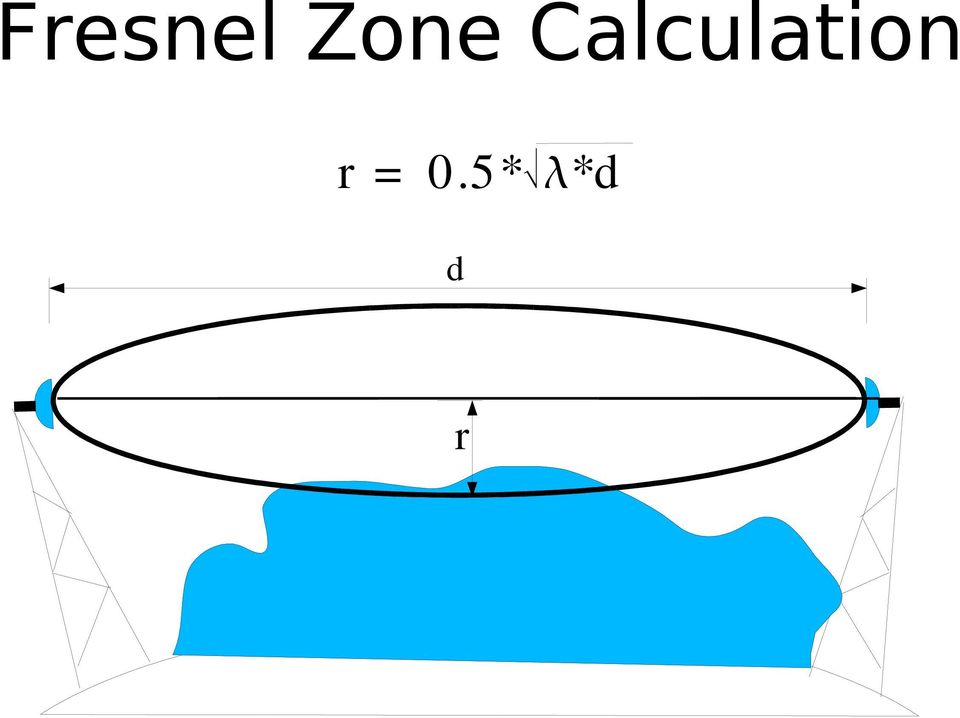
13 Fresnel Zone Calculation r = 0.5* *d d 60% free r Ideally would be a 80%-free Fresnel Zone, no significant signal loss. Keep at least 60 % of the Zone free that will sacrifice some signal strength.

14 Fresnel Zone &Terrain Roughness If the Fresnel Zone is 60% clear, there will be attenuation in addition to regular free space loss. A rough estimation: Flat surface adds 2 db attentuation to free space attenuation Small houses of similar height / forest adds about 3 db loss Urban area adds estimated loss of about 5 db

15 How to deal with the Fresnel Zone The diameter of the Fresnel Zone depends on the length of the link and the wavelength. Keep it small by choosing the highest frequency smallest wavelength you can use. Frequ en cy = Wavelen gth = Fresn el Zon e ø A tradeoff for using 5.x Ghz instead of 2.4x is bigger free space attenuation, higher sensitivity to rain and fog. But Antennae have considerably higher gain at higher frequencies.

16 Earth Bulge
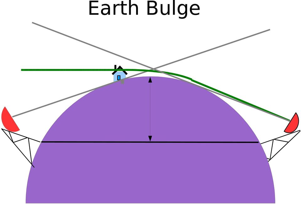
17 Earth Bulge h d1 d 2 Geodaetic Bulge h= * (d1*d2) Bulge with Refraction: h= *((d1*d2)/1.333)

18 Antenna height calculation Calculate the height of the antennae (depending on Fresel Zone radius, landscape, earth bulge). Example: 30 km distance. Frequency 5GHz Wavelength = Speed of light/frequency = m/sec / Hz =0.06 m Fresnel zone radius for 5GHz : 21.21m = 0.5* m * 0.06m Fresnel zone radius with 40% obstructions, 60 % clear: 12.73m = 21.21m * 0.6

19 Antenna height calculation Earth bulge (in the middle between towers): 13.23m= *((15km*15km)/1.333) Tower height: 25.96m=12.73m+13.23m
/1.")
20 Link calculation (Example values...) Antenna + 24 db Propagation Loss - 135dB Antenna + 24 db Plug -1dB Plug-1dB Cable -1dB Cable -1dB Plug-1dB Plug-1dB WiFi- Interface TX Power +20dB WiFi- Interface RX Received Signal - 73dB -73dB = 20dB 1dB 1dB 1dB + 24dB 135dB + 24dB 1dB 1dB - 1dB

21 Transmitter(TX)-Power More is more, but does not really help much if the Fresnel Zone is obstructed... more power = more powerful disturbing reflections Good receiver sensitivity is more important! Measurment unit is mw or dbm. 1mW = 0 dbm 16mW = 12 dbm 2mW = 3 dbm 32mW = 15 dbm 4mW = 6 dbm 64mW = 18 dbm 8mW = 9 dbm 128mW = 21 dbm
22 Receiver sensitivity Card Mbps Senao NL/SL-2511CD PLUS EXT2 (200mW, 2 MMCX connectors) Cisco 350 Series (100mW) Compaq MultiPort W200 (32mW) Lucent/Agere/Proxim Orinoco Gold/Silver Card (32mW) Netgear MA401 (PCMCIA) Microsoft MN-520 (PCMCIA16)
23 A Uber-Wifi-Card ;-) High Power (26dbm) Atheros 6G Mini-PCI Adapter-NMP-8602 Receive Sensitivity (Typical) a: 6Mbps, 54Mbps g: 6Mbps, 54Mbp b: 1Mbps 11Mbps Tx-Power 2.412~2.472G(IEEE802.11g) 26 ± 23 ± 2.412~2.472G(IEEE802.11b) 26 ± 2, 5.5 and ~ 5.825GHz 20 ± 17 ±
24 Free space attenuation km -db -db
25 Rule of thump for WiFi-frequencies: 3 db more attentuation for 50% more distance 6 db more attentuation for 100% more distance
26 Link Fade 0.1dB/km (worst case)
27 Big grid dish 24dBi 2.4GHz 27dBi 5.8GHz Antennae
28 Cables and plugs Cable Aircom Plus Aircell 7 LMR400 RG213 Plugs N-Type Don't use crimpplugs not waterproof Wrap outdoor connectors with self-amalgaming tape. Don't worry too much about signal losses of different cable just keep them as short as possible.
29 Example Free space loss 30 km = dB fade margin = - 15dB terrain roughness = - 5dB total propagation loss = dB cable,connector loss = - 6dB total loss = dB antenna gain 2x = + 54dB txpower (senao) = + 23dB signal strength at receiver input = dB
30 Calculation within legal limits Effective radiated power ERP The sum of all gains and losses on the transmitter side. 2.4GHz in Germany 20dBm 5.8GHz 30dBm Better to have less TX-Power and more antenna gain. Plug -1dB Antenna + 24 db Cable -1dB Plug-1dB WiFi- Interface TX ERP= 41dBm Power +20dB
31 Example: 10km Antenna + 27 db Propagation Loss - 133dB Antenna + 27 db Plug -1dB Plug-1dB Cable -1dB Cable -1dB Plug-1dB Plug-1dB WiFi- Interface TX Power +6dB WiFi- Interface RX Received Signal - 81dB
32 Long distance timing issues of b Propagation delay: 1 sec for 299 m 100 sec for 29. 9km b provides very small timeslots for successful transmissions. 10 sec Short Inter- Frame Spacing interval 50 sec Distributed Point Coordination Function Inter- Frame Space 640 sec Contention Window
33 Long distance timeing issues Some chipsets just do the trick out of the box, while others don't... Working: Prism 2, 2.5, 3 Orinoco b Atheros a,b,g (untested, but tools are available to adjust timeslots for distance with athctrl)
34 Alternative: Adhoc-demomode Available for Atheros, Prism and Orinoco Proprietary , doesn't necessarily work between different chipsets... Provided by drivers: orinoco hostap madwifi Doesn't send acknowledgements...
35 Initial alignment Kismet
36 Links This document: Online link calculator:
This Antenna Basics reference guide includes basic information about antenna types, how antennas work, gain, and some installation examples.
 Antenna Basics This Antenna Basics reference guide includes basic information about antenna types, how antennas work, gain, and some installation examples. What Do Antennas Do? Antennas transmit radio
Understanding Range for RF Devices
 Understanding Range for RF Devices October 2012 White Paper Understanding how environmental factors can affect range is one of the key aspects to deploying a radio frequency (RF) solution. This paper will
An Introduction to Microwave Radio Link Design
 An Introduction to Microwave Radio Link Design Table of Contents 1 Introduction... 3 2 Radio Link Engineering main steps... 3 2.1 Make Path profile... 3 2.2 Calculate Free Space Loss (FSL)... 4 2.3 Calculate
is the power reference: Specifically, power in db is represented by the following equation, where P0 P db = 10 log 10
 RF Basics - Part 1 This is the first article in the multi-part series on RF Basics. We start the series by reviewing some basic RF concepts: Decibels (db), Antenna Gain, Free-space RF Propagation, RF Attenuation,
Radio Physics for Wireless Devices and Networking. The Radio Physics of WiFi. By Ron Vigneri
 Radio Physics for Wireless Devices and Networking By Ron Vigneri The Radio Physics of WiFi The standard for wireless LANs (WLANs) was completed in 1997 with the release of the IEEE 802.11 specification
WiFi Antenna Installation Best Practices Design Guide
 WiFi Antenna Installation Best Practices Design Guide Choosing the right antenna The first step to building a wireless network is choosing the correct antenna for your application. Coverage and range will
Wireless Internet. Is an system to provide connectivity to customers to the Internet. Service Provider (WISP) TECHNICAL INFO.
 TECHNICAL INFO.") Description The Service Provider System (WISP) is an integrated Metropolitan Area Network (MAN) system of connecting customers to the. High-speed wireless data links are used to provide access on a point-to-point
Description The Service Provider System (WISP) is an integrated Metropolitan Area Network (MAN) system of connecting customers to the. High-speed wireless data links are used to provide access on a point-to-point
EE4367 Telecom. Switching & Transmission. Prof. Murat Torlak
 Path Loss Radio Wave Propagation The wireless radio channel puts fundamental limitations to the performance of wireless communications systems Radio channels are extremely random, and are not easily analyzed
communication over wireless link handling mobile user who changes point of attachment to network
 Wireless Networks Background: # wireless (mobile) phone subscribers now exceeds # wired phone subscribers! computer nets: laptops, palmtops, PDAs, Internet-enabled phone promise anytime untethered Internet
Avaya WLAN 9100 External Antennas for use with the WAO-9122 Access Point
 Avaya WLAN 9100 External Antennas for use with the WAO-9122 Access Point Overview To optimize the overall performance of a WLAN in an outdoor deployment it is important to understand how to maximize coverage
Antenna Deployment Technical Brief
 ProCurve Networking Antenna Deployment Technical Brief Introduction... 2 Antenna types... 2 Omni directional antennas... 2 Directional antennas... 2 Diversity antennas... 3 High gain directional antennas...
WiFi Installs Frequently Asked Questions Version 1.3
 The Allendale Group. Pindar Road, Hoddesdon Herts. EN11 0BZ. Worldwide Suppliers of High Grade Antennas for Wireless Networks... W: Wifi-antennas.co.uk E: [email protected] WiFi Installs Frequently
UHF Wave Propagation Losses Beyond 40 Percent Fresnel Zone Radius in South-South, Nigeria
 UHF Wave Propagation Losses Beyond 40 Percent Fresnel Zone Radius in South-South, Nigeria D. E. Bassey 1, Aniefiok O. Akpan 2, E Udoeno 3 1 Electronics and Computer Technology Unit, Department of Physics,
The Application of Land Use/ Land Cover (Clutter) Data to Wireless Communication System Design
 Data to Wireless Communication System Design") Technology White Paper The Application of Land Use/ Land Cover (Clutter) Data to Wireless Communication System Design The Power of Planning 1 Harry Anderson, Ted Hicks, Jody Kirtner EDX Wireless, LLC Eugene,
Technology White Paper The Application of Land Use/ Land Cover (Clutter) Data to Wireless Communication System Design The Power of Planning 1 Harry Anderson, Ted Hicks, Jody Kirtner EDX Wireless, LLC Eugene,
Antennas & Propagation. CS 6710 Spring 2010 Rajmohan Rajaraman
 Antennas & Propagation CS 6710 Spring 2010 Rajmohan Rajaraman Introduction An antenna is an electrical conductor or system of conductors o Transmission - radiates electromagnetic energy into space o Reception
Basic Outdoor WiFi Network Planning
 Basic Outdoor WiFi Network Planning Michael E Fox, N6MEF Santa Clara County ARES /RACES SIG Meeting 15 May 2014 Revised: 16 May 2014 ARES and Amateur Radio Emergency Service are registered service marks
Troubleshooting Problems Affecting Radio Frequency Communication
 Troubleshooting Problems Affecting Radio Frequency Communication Document ID: 8630 Refer to the Cisco Wireless Downloads (registered customers only) page in order to get Cisco Aironet drivers, firmware
AN INTRODUCTION TO TELEMETRY PART 1: TELEMETRY BASICS
 AN INTRODUCTION TO TELEMETRY PART 1: TELEMETRY BASICS Telemetry is defined as the sensing and measuring of information at some remote location and then transmitting that information to a central or host
Part I: Wireless System Characteristics
 Part I: Wireless System Characteristics Smart grid technology holds great promise of cleaner air, more efficient power, and lower greenhouse gas emissions. In a smart grid system, the system itself will
Attaching the PA-A1-ATM Interface Cables
 CHAPTER 4 Attaching the PA-A1-ATM Interface Cables To continue your PA-A1-ATM port adapter installation, you must attach the port adapter cables. The instructions that follow apply to all supported platforms.
Selecting Receiving Antennas for Radio Tracking
 Selecting Receiving Antennas for Radio Tracking Larry B Kuechle, Advanced Telemetry Systems, Inc. Isanti, Minnesota 55040 [email protected] The receiving antenna is an integral part of any radio location
ITRAINONLINE MMTK BASIC RADIO PHYSICS HANDOUT
 ITRAINONLINE MMTK BASIC RADIO PHYSICS HANDOUT Developed by: Sebastian Buettrich, wire.less.dk Edited by: Alberto Escudero Pascual, IT +46 Table of Contents 1. About this document...1 1.1 Copyright information...2
Case Study WIRELESS EXCELLENCE. Case Study MobiNil selects CableFree for GSM network expansion. Cellular Wireless Networks. About Wireless Excellence
 Case Study WIRELESS EXCELLENCE Case Study MobiNil selects CableFree for GSM network expansion Cellular Wireless Networks About Wireless Excellence Founded in 1995 and with headquarters in Oxford UK, Wireless
Feedback Alarm and Its Troubleshooting For Improvement of Microwave Link
 IOSR Journal of Electronics and Communication Engineering (IOSR-JECE) e-issn: 2278-2834,p- ISSN: 2278-8735.Volume 9, Issue 2, Ver. VIII (Mar - Apr. 2014), PP 15-24 Feedback Alarm and Its Troubleshooting
Omni Antenna vs. Directional Antenna
 Omni Antenna vs. Directional Antenna Document ID: 82068 Contents Introduction Prerequisites Requirements Components Used Conventions Basic Definitions and Antenna Concepts Indoor Effects Omni Antenna Pros
Internal GPS Active Patch Antenna Application Note
 Internal GPS Active Patch Antenna Application Note APN-13-8-002/A Page 1 of 14 1. BASICS 2. APPLICATIONS 3. SIZE 4. SHAPE 5. GROUND PLANE 6. IMPEDANCE 7. BANDWIDTH 8. VSWR 9. LINK BUDGET 10. GAIN 11. NOISE
Wireless Networking over Extended Range
 Wireless Networking over Extended Range Technology options for optimizing long range wireless connectivity Technical Note This paper has been compiled using real life data collected over the last 5 years
Cisco - Calculating the Maximum Attenuation for Optical Fiber Links
 Page 1 of 5 Calculating the Maximum Attenuation for Optical Fiber Links Document ID: 27042 Contents Introduction Prerequisites Requirements Components Used Conventions What is Attenuation? Wavelength Estimate
Electronic Communications Committee (ECC) within the Conference of Postal and Telecommunications Administrations (CEPT)
 within the Conference of Postal and Telecommunications Administrations (CEPT)") Page 1 Electronic Communications Committee (ECC) within the Conference of Postal and Telecommunications Administrations (CEPT) ECC RECOMMENDATION (05)08 (replacing recommendations T/R 20-08 and 22-07)
Page 1 Electronic Communications Committee (ECC) within the Conference of Postal and Telecommunications Administrations (CEPT) ECC RECOMMENDATION (05)08 (replacing recommendations T/R 20-08 and 22-07)
Location management Need Frequency Location updating
 Lecture-16 Mobility Management Location management Need Frequency Location updating Fig 3.10 Location management in cellular network Mobility Management Paging messages Different paging schemes Transmission
Antenna Diversity in Wireless Local Area Network Devices
 Antenna Diversity in Wireless Local Area Network Devices Frank M. Caimi, Ph.D. Kerry L. Greer Jason M. Hendler January 2002 Introduction Antenna diversity has been used in wireless communication systems
Mobile Phones: Jargon Explained
 Mobile Phones: Jargon Explained 2G 3G Aerial Second Generation Mobile Phone System. See GSM See Third Generation Mobile Phone System. Device designed to radiate and receive electromagnetic energy. Antenna
Introduction to RF Engineering. Andrew CLEGG
 Introduction to RF Engineering Andrew CLEGG 1 Comparing the Lingo Radio Astronomers Speak a Unique Vernacular We are receiving interference from your transmitter at a level of 10 janskys What the ^#$&
Cellular Wireless Antennas
 Cellular Wireless Antennas A Technical Brief GarrettCom Inc., November 2010 Overview The Cellular Wireless Antenna Technical brief is provided to assist with the design and deployment of the DX940 Cellular
INTRODUCTION FIGURE 1 1. Cosmic Rays. Gamma Rays. X-Rays. Ultraviolet Violet Blue Green Yellow Orange Red Infrared. Ultraviolet.
 INTRODUCTION Fibre optics behave quite different to metal cables. The concept of information transmission is the same though. We need to take a "carrier" signal, identify a signal parameter we can modulate,
Municipal Mesh Network Design
 White Paper Municipal Mesh Network Design Author: Maen Artimy 1 Summary This document provides a wireless mesh network design for the downtown area of the Town of Wolfville, Nova Scotia. This design serves
Potential Effects of Wind Turbine Generators on Pre-Existing RF Communication Networks SEAN YUN. June 2009. Software Solutions in Radiocommunications
 Potential Effects of Wind Turbine Generators on Pre-Existing RF Communication Networks June 2009 SEAN YUN 2 2 Abstract In an effort to help preserve the ozone and the availability of diminishing natural
RECOMMENDATION ITU-R P.1546-1. Method for point-to-area predictions for terrestrial services in the frequency range 30 MHz to 3 000 MHz
 Rec. ITU-R P.546- RECOMMENDATION ITU-R P.546- Method for point-to-area predictions for terrestrial services in the frequency range 30 MHz to 3 000 MHz (200-2003) The ITU Radiocommunication Assembly, considering
LOW LOSS CABLE PAG. 1
 LOW LOSS CABLE PAG. 1 INTRODUCTION Following many requests we received regarding the need for low-loss custom cable assemblies, we have set up a special production of high performance coaxial cable assemblies
FOM-5A, 6A. Asynchronous Fiber Optic Modem
 FOM-5A, 6A Asynchronous Fiber Optic Modem FEATURES Asynchronous transmission at up to 19.2 kbps Transmission range up to 3 km (1.8 mi), regardless of data rate Full- or half-duplex Transfers one control
SHARING BETWEEN TERRESTRIAL FLIGHT TELEPHONE SYSTEM (TFTS) AND RADIO ASTRONOMY IN THE 1.6 GHz BAND. Paris, May 1992
 AND RADIO ASTRONOMY IN THE 1.6 GHz BAND. Paris, May 1992") European Radiocommunications Committee (ERC) within the European Conference of Postal and Telecommunications Administrations (CEPT) SHARING BETWEEN TERRESTRIAL FLIGHT TELEPHONE SYSTEM (TFTS) AND RADIO
European Radiocommunications Committee (ERC) within the European Conference of Postal and Telecommunications Administrations (CEPT) SHARING BETWEEN TERRESTRIAL FLIGHT TELEPHONE SYSTEM (TFTS) AND RADIO
Cisco Aironet Antennas and Accessories
 Reference Guide Cisco Aironet Antennas and Accessories Overview Executive Overview This antenna reference guide explains issues and concerns about antennas used with a Cisco Aironet wireless LAN system
Radio-Tracking of Birds: Regulation and Ruling of Radio Frequencies
 Radio-Tracking of Birds: Regulation and Ruling of Radio Frequencies Animal Tracking workshop @ Hula Valley 7-9 Nov 1 Dr. Haim Mazar; Israeli Ministry of Communications Vice Chairman ITU-R Study Group 1
Attenuation (amplitude of the wave loses strength thereby the signal power) Refraction Reflection Shadowing Scattering Diffraction
 Refraction Reflection Shadowing Scattering Diffraction") Wireless Physical Layer Q1. Is it possible to transmit a digital signal, e.g., coded as square wave as used inside a computer, using radio transmission without any loss? Why? It is not possible to transmit
Wireless Physical Layer Q1. Is it possible to transmit a digital signal, e.g., coded as square wave as used inside a computer, using radio transmission without any loss? Why? It is not possible to transmit
GSM frequency planning
 GSM frequency planning Band : 890-915 and 935-960 MHz Channel spacing: 200 khz (but signal bandwidth = 400 khz) Absolute Radio Frequency Channel Number (ARFCN) lower band: upper band: F l (n) = 890.2 +
Correlation between OATS, Fully Anechoic Room and GTEM Radiated Emissions
 Correlation between OATS, Fully Anechoic Room and GTEM Radiated Emissions Stephen Clay Introduction: Just a few words about myself. My name is Steve Clay and I work for Nokia Mobile Phones, and it is my
5. ANTENNA TYPES. Figure 5. The vertical dipole and its electromagnetic equivalent, the vertical monopole
 Antennas can be classified in several ways. One way is the frequency band of operation. Others include physical structure and electrical/electromagnetic design. The antennas commonly used for LMR both
Receiving Saorview Digital Terrestrial Television
 Receiving Saorview Digital Terrestrial Television Introduction RTÉ NL Nutley Building Donnybrook Dublin 4 Tel: 01-2082223 Fax: 01-2082283 Email: [email protected] Web: www.rtenl.ie Saorview s Digital Terrestrial
Signal directionality Lower frequency signals are omnidirectional Higher frequency signals can be focused in a directional beam
 Transmission Media Transmission medium Physical path between transmitter and receiver May be guided (wired) or unguided (wireless) Communication achieved by using em waves Characteristics and quality of
Sol: Optical range from λ 1 to λ 1 +Δλ contains bandwidth
 1. Use Figure 3.47 and Figure 3.50 to explain why the bandwidth of twisted-wire pairs and coaxial cable decreases with distance. Figure 3.47 figure 3.50 sol: The bandwidth is the range of frequencies where
Wireless Tips and Tricks for RouterOS v6. MUM South Africa 2013 Johannesburg Uldis Cernevskis MikroTik
 Wireless Tips and Tricks for RouterOS v6 MUM South Africa 2013 Johannesburg Uldis Cernevskis MikroTik Topics Quickset for Wireless Transparent wireless links Useful configuration settings and features
FURTHER READING: As a preview for further reading, the following reference has been provided from the pages of the book below:
 FURTHER READING: As a preview for further reading, the following reference has been provided from the pages of the book below: Title: Cellular/PCS Management Author: Paul Beddel Publisher: McGraw-Hill
Pointers on using the 5GHz WiFi bands
 Pointers on using the 5GHz WiFi bands Legalities In the UK, there are two main types of radio devices that use the 5GHz frequency bands. The most common are those devices that conform to the 11a standard.
Zero-Variable Wireless Infrastructure Deployment. Datasheet. Models: BM2HP, BM5HP. Completely integrated Radio
 Zero-Variable Wireless Infrastructure Deployment Models: BM2HP, BM5HP Completely integrated Radio Directly plugs into any Antenna that has a Type N female connector Robust Weatherproof Design Overview
NAVICOM DYNAMICS RTK BASE STATION INSTALLATION AND COMMISSIONING INSTRUCTIONS
 NAVICOM DYNAMICS RTK BASE STATION INSTALLATION AND COMMISSIONING INSTRUCTIONS 1. Locate a suitable position inside the building to install the Base Station enclosure where mains power (240V AC) is available
You will need the following pieces of equipment to complete this experiment:
 UNIVERSITY OF TORONTO FACULTY OF APPLIED SCIENCE AND ENGINEERING The Edward S. Rogers Sr. Department of Electrical and Computer Engineering ECE422H1S: RADIO AND MICROWAVE WIRELESS SYSTEMS EXPERIMENT 3:
Data Transmission. Raj Jain. Professor of CIS. The Ohio State University. Columbus, OH 43210 [email protected] http://www.cis.ohio-state.
 Data Transmission Professor of CIS Columbus, OH 43210 [email protected] http://www.cis.ohio-state.edu/~jain/ 2-1 Overview Time Domain and Frequency Domain Bit, Hertz Decibels Data vs Signal Attenuation, Delay
Cisco Aironet Antennas and Accessories
 Cisco Aironet Antennas and Accessories Overview Executive Overview This antenna reference guide is intended to provide information to assist in understanding the issues and concerns of antennas used with
Data Transmission. Data Communications Model. CSE 3461 / 5461: Computer Networking & Internet Technologies. Presentation B
 CSE 3461 / 5461: Computer Networking & Internet Technologies Data Transmission Presentation B Kannan Srinivasan 08/30/2012 Data Communications Model Figure 1.2 Studying Assignment: 3.1-3.4, 4.1 Presentation
Small-Cell Wireless Backhauling
 Small-Cell Wireless Backhauling A Non-Line-of-Sight Approach for Point-to-Point Microwave Links M. Coldrey*, H. Koorapaty**, J.-E. Berg***, Z. Ghebretensaé***, J. Hansryd****, A. Derneryd*, S. Falahati***
RADIO WAVE TRANSMISSION PRINCIPLES. What Are Radio Waves? 74 Chapter 3 How Wireless Works
 3 C H A P T E R T H R E E HOW WIRELESS WORKS Copyright 2005 by Course Technology. All rights reserved.this publication is protected by federal copyright law. No part of this publication 73 74 Chapter 3
Basics of Radio Wave Propagation
 Basics of Radio Wave Propagation Iulian Rosu, YO3DAC / VA3IUL, http://www.qsl.net/va3iul/ Propagation Modes Ground-wave propagation o Follows contour of the earth o Can Propagate considerable distances
International Civil Aviation Organization
 CNS/MET SG/16 IP/30 (Rev.) Agenda Item 7 (3) 23/07/12 International Civil Aviation Organization SIXTEENTH MEETING OF THE COMMNICATIONS/NAVIGATION/SRVEILLANCE AND METEOROLOGY SB-GROP (CNS/MET SG/16) OF
WiFi hardware Vendors, Choices & Procurement Sebastian Büttrich, wire.less.dk edit: March 2010 http://creativecommons.org/licenses/by-nc-sa/3.
 WiFi hardware Vendors, Choices & Procurement Sebastian Büttrich, wire.less.dk edit: March 2010 http://creativecommons.org/licenses/by-nc-sa/3.0/ Goals To be aware of important criteria for selecting wireless
EECC694 - Shaaban. Transmission Channel
 The Physical Layer: Data Transmission Basics Encode data as energy at the data (information) source and transmit the encoded energy using transmitter hardware: Possible Energy Forms: Electrical, light,
RF Path Loss & Transmission Distance Calculations
 RF Path Loss & Transmission Distance Calculations By Walter Debus Director of Engineering Axonn, LLC Technical Memorandum August 4, 2006 INTRODUCTION DOC# 8545-0003-01 For radio transmission systems that
Environmental Monitoring: Guide to Selecting Wireless Communication Solutions
 Environmental Monitoring: Guide to Selecting Wireless Communication Solutions By: Scott South Published in WaterWorld, January 2005 (Page 48) Rapidly growing demands for information and increased productivity
NON-LINE OF SIGHT: TECHNOLOGY & IMPLEMENTATION
 SOLECTEK WHITE PAPER NON-LINE OF SIGHT: TECHNOLOGY & IMPLEMENTATION Introduction To many industry insiders, the promise of broadband wireless access (BWA) is clear. Delivery of last mile, enterprise infrastructure
WIB250A5 Series PC/104+ 802.11b/g/a/h WLAN Modules
 Product Overview WIB250A5 series are full-featured wireless devices that use the PC/104 Plus form factor. WIB250A5 works with PC/104 Plus and PCI-104 CPU modules and upgrades your embedded system into
Measuring of optical output and attenuation
 Measuring of optical output and attenuation THEORY Measuring of optical output is the fundamental part of measuring in optoelectronics. The importance of an optical power meter can be compared to an ammeter
PRO 5000 CPE 1D Quick Installation Guide
 PRO 5000 CPE 1D Quick Installation Guide Introduction This Quick Installation Guide covers the basic installation of the PRO 5000 CPE. For more information, refer to the relevant sections in the Product
Fixed Wireless Fact Sheet
 National Broadband Network Fixed Wireless Fact Sheet What is the National Broadband Network? The National Broadband Network (NBN) is designed to provide high speed broadband access to 100 per cent of Australian
Alternative Wireless Access Technologies. Heinz Willebrand, CEO & President
 Alternative Wireless Access Technologies Heinz Willebrand, CEO & President The Mobile Wireless Backhaul Dilemma Backhaul Capacity Requirements Increasing Single 4G/LTE base station capacity requirement
MANUAL FOR RX700 LR and NR
 MANUAL FOR RX700 LR and NR 2013, November 11 Revision/ updates Date, updates, and person Revision 1.2 03-12-2013, By Patrick M Affected pages, ETC ALL Content Revision/ updates... 1 Preface... 2 Technical
T = 1 f. Phase. Measure of relative position in time within a single period of a signal For a periodic signal f(t), phase is fractional part t p
, phase is fractional part t p") Data Transmission Concepts and terminology Transmission terminology Transmission from transmitter to receiver goes over some transmission medium using electromagnetic waves Guided media. Waves are guided
Data Transmission Concepts and terminology Transmission terminology Transmission from transmitter to receiver goes over some transmission medium using electromagnetic waves Guided media. Waves are guided
Deliberant.com, 2011. Technology review
 Technology review 11N advantages Parameter 802.11a/g 802.11n 2x2 Improvement factor Data rate, Mbps 108 300 2.7x Max throughput, h t Mbps 45 150 3.3x3 Spectral efficiency, bit/hz 1.125 3.75 3.3x Signal
Microwave QSOs with the aid of airplane reflection. Wolf-Henning Rech DF9IC in JN48iw http://www.df9ic.de
 Microwave QSOs with the aid of airplane reflection Wolf-Henning Rech DF9IC in JN48iw http://www.df9ic.de Content Some theory Observations on beacons Experience from QSOs Airplane tracking with ADS-B A
DVB-SH. Radio Network Planning Tool. (Release 4.2)
") DVB-SH Radio Network Planning Tool (Release 4.2) by AWE Communications GmbH. All rights reserved 1 1 Introduction 1.1 Overview Digital Video Broadcasting Satellite to Handheld (DVB-SH) aims to provide
DVB-SH Radio Network Planning Tool (Release 4.2) by AWE Communications GmbH. All rights reserved 1 1 Introduction 1.1 Overview Digital Video Broadcasting Satellite to Handheld (DVB-SH) aims to provide
Wireless Feasibility Survey And Site Survey For Sandersville, GA. Jay Sexton and Jeffrey Lee Georgia Tech Research Institute
 Wireless Feasibility Survey And Site Survey For Sandersville, GA Jay Sexton and Jeffrey Lee Georgia Tech Research Institute On November 7-8, 2001, two representatives from the Georgia Tech Research Institute
COLLATED QUESTIONS: ELECTROMAGNETIC RADIATION
 COLLATED QUESTIONS: ELECTROMAGNETIC RADIATION 2011(2): WAVES Doppler radar can determine the speed and direction of a moving car. Pulses of extremely high frequency radio waves are sent out in a narrow
EMC Basics. Speaker : Alain Lafuente. [email protected]
 EMC Basics Speaker : lain Lafuente [email protected] WHT IS EMC? 2 CE Marking With the formation of the single European market, standardization was required to remove technical barriers to trade.
WLAN-Antenna Project
 Report WLAN-Antenna Project PPS Antenna Tower Uetliberg FS 08 Mathias Aebersold Matthias Bucher Page 1 of 7 For this project we wanted to build a WLAN-Antenna which has different and for some usage better
1. Introduction. FER-Zagreb, Satellite communication systems 2011/12
 1. Introduction Topics History Characteristics of satellite communications Frequencies Application 1 History Arthur C. Clark suggested in 1945. Earth coverage with 3 geostationary satellites. On 4th of
Mid-Range Complete Radio Station Package
 Equipment, Training and Technical Services for Community Radio www.radioactive.org.uk [email protected] Tel: +44 (0) 207 3723815 Fax: +44 (0) 20 89927115 Mid-Range Complete Radio Station Package
airmax Wireless Broadband CPE Datasheet Models: AG-HP-2G16, AG-HP-2G20, AG-HP-5G23, AG-HP-5G27 High Performance, Long Range Integrated InnerFeed CPE
 airmax Wireless Broadband CPE Models: AG-HP-2G16, AG-HP-2G20, AG-HP-5G23, AG-HP-5G27 High Performance, Long Range Integrated InnerFeed CPE Easy Assembly and Installation Utilizing InnerFeed technology,
Antennas & Transmission Lines
 4 Antennas & Transmission Lines The transmitter that generates the RF 1 power to drive the antenna is usually located at some distance from the antenna terminals. The connecting link between the two is
Radio Network Planning Tools Basics, Practical Examples & Demonstration on NGN Network Planning Part I
 Radio Network Planning Tools Basics, Practical Examples & Demonstration on NGN Network Planning Part I Roland Götz LS telcom AG Regional Seminar on evolving network infrastructures to NGN and related Planning
Engineering Sciences 151. Electromagnetic Communication Laboratory Assignment 3 Fall Term 1998-99
 Engineering Sciences 151 Electromagnetic Communication Laboratory Assignment 3 Fall Term 1998-99 WAVE PROPAGATION II: HIGH FREQUENCY SLOTTED LINE AND REFLECTOMETER MEASUREMENTS OBJECTIVES: To build greater
RSSI LED IP-67. Virtual. HTTPS WISP Bridge
 AirMax DUO 802.11a/b/g Dual Radio Base Station T he AirMax DUO is the latest generation of AirLive Outdoor Base Station that incorporates everything we know about wirelessa feat from the company that starts
Unidirectional Transmitter/ Receiver Units Introduction
 Unidirectional Transmitter/ Receiver Units Introduction Wireless Input/Output (I/O) connects directly to analog, discrete and pulse transducer signals. The signals are transmitted by radio and either re-created
Analysis of radio wave propagation in Lagos environs
 AMERICAN JOURNAL OF SCIENTIFIC AND INDUSTRIAL RESEARCH 2011, Science Huβ, http://www.scihub.org/ajsir ISSN: 2153-649X doi:10.5251/ajsir.2011.2.3.438.455 Analysis of radio wave propagation in Lagos environs
Mitel DECT Base Stations
 Mitel DECT Base Stations On-site Mobility for Professionals The Mitel BS300 range of base stations offers a variety of coverage patterns to suit different situations. By choosing the right mix of base
Outdoor Propagation Prediction in Wireless Local Area Network (WLAN)
") Outdoor Propagation Prediction in Wireless Local Area Network (WLAN) Akpado K.A 1, Oguejiofor O.S 1, Abe Adewale 2, Femijemilohun O.J 2 1 Department of Electronic and Computer Engineering, Nnamdi Azikiwe
Outdoor Propagation Prediction in Wireless Local Area Network (WLAN) Akpado K.A 1, Oguejiofor O.S 1, Abe Adewale 2, Femijemilohun O.J 2 1 Department of Electronic and Computer Engineering, Nnamdi Azikiwe
Outdoor CPE CPE210 / CPE220 / CPE510 / CPE520
 Installation Guide Outdoor CPE CPE210 / CPE220 / CPE510 / CPE520 CONTENTS Overview Hardware Connection Site Consideration Connection and Installation Lightning & ESD Protection Software Configuration
Volts/m For EMC and Antenna Measurement
 Application Note #0430 September 2012 Revised: Volts/m For EMC and Antenna Measurement Application Note Image courtesy of Wikipedia Commons This note describes the concept of electric field strength in
SkyWay-Mobile. Broadband Wireless Solution
 SkyWay-Mobile Broadband Wireless Solution Wonderful World of Wireless The era of ubiquitous communication has arrived. Region by region, country by country and continent by continent, wireless connectivity
Wireless Ethernet LAN (WLAN) General 802.11a/802.11b/802.11g FAQ
 General 802.11a/802.11b/802.11g FAQ") Wireless Ethernet LAN (WLAN) General 802.11a/802.11b/802.11g FAQ Q: What is a Wireless LAN (WLAN)? Q: What are the benefits of using a WLAN instead of a wired network connection? Q: Are Intel WLAN products
Wireless Ethernet LAN (WLAN) General 802.11a/802.11b/802.11g FAQ Q: What is a Wireless LAN (WLAN)? Q: What are the benefits of using a WLAN instead of a wired network connection? Q: Are Intel WLAN products
FSLIMRF05-10 - 15-20 - 25
 1. INTRODUCTION FSLIMRF is a fully wireless, battery-powered infrared beam barrier for the protection of doors and windows with alarm radio transmission. The barrier is made up of two aluminium sections
5GHz 300Mbps 13dBi Outdoor CPE
 5GHz Mbps 13dBi Outdoor CPE Features Built-in 13dBi 2x2 dual-polarized directional MIMO antenna Adjustable transmission power from to dbm/5mw System-level optimizations for more than 15km+ long range wireless