International Civil Aviation Organization
|
|
|
- Coral Oliver
- 8 years ago
- Views:
Transcription
1 CNS/MET SG/16 IP/30 (Rev.) Agenda Item 7 (3) 23/07/12 International Civil Aviation Organization SIXTEENTH MEETING OF THE COMMNICATIONS/NAVIGATION/SRVEILLANCE AND METEOROLOGY SB-GROP (CNS/MET SG/16) OF APANPIRG Bangkok, Thailand, July 2012 Agenda Item 7: Aeronautical Electromagnetic Spectrum tilization 3) Radio spectrum management related issues HANDBOOK ON RADIO FREQENCY SPECTRM REQIREMENTS FOR CIVIL AVIATION: PART II FREQENCY ASSIGNMENT PLANNING CRITERIA FOR AERONATICAL COMMNICATION AND NAVIGATION SYSTEMS (Presented by the Secretariat) SMMARY This paper presents the current status of the draft new Part II of the Handbook on Radio Frequency Spectrum Requirements for Civil Aviation, (ICAO Doc 9718), developed by the ACP WG-F. The paper provides information on the detailed frequency assignment planning criteria for VHF air/ground communication systems and the approval procedures of these, through amending the current provisions in the Regional Plan for the Asia and Pacific Regions through APANPIRG. Action required by the meeting is indicated in paragraph 4 at the end of the paper. This paper relates to Strategic Objectives A: Safety - Enhance global civil aviation safety C: Environmental Protection and Sustainable Development of Air Transport - Foster harmonized and economically viable development of international civil aviation that does not unduly harm the environment Global Plan Initiatives: GPI-23 Aeronautical Radio Spectrum 1. Introduction/Discussion 1.1 The ICAO Aeronautical Communications Panel is progressing, through ACP Working Group F, the development of detailed frequency assignment planning criteria for aeronautical systems for which the ICAO Regional Offices coordinate frequency assignment planning
 SMMARY This paper presents the current status of the draft")
2 CNS/MET SG/16 IP/30 (Rev.) -2- Agenda Item 7 (3) 23/07/12 and publishes, from time to time, lists with coordinated frequency assignments (COM Lists). These lists are related to the Regional Air Navigation Plans. 1.2 To date, updated frequency assignment planning criteria, intended for Global use, for VHF air/ground communication systems operating in the frequency band MHz is nearing completion. 2. Need for updating frequency assignment planning criteria. 2.1 In most Regions, the frequency assignment planning criteria that are being used, although having been subjected to limited updates over the recent years, are limited with respect to the application in frequency assignment planning. The methodology that is being completed in ICAO allows for more flexibility in frequency planning and improving the efficient use of the available spectrum on a global basis. It also supports developing a global database of frequency assignment as part of the Global Air Navigation Plan. 2.2 Annex 10, Volume V is subject to a revision as per State letter 2012/33 dated 24 April This revision has removed from Annex 10 most of the current guidance material and moved this, amended as necessary, in the Handbook, Volume II. This brings together, in a single publication, the spectrum management and the frequency management aspect of use by aviation of aeronautical frequency bands. 2.3 The current material in the Handbook Volume II concentrates on revised frequency assignment planning criteria for air/ground VHF communication systems (voice and data) and is based on the work that has been completed to date by the ACP Working Group. It is expected that Part II will be available for publication in a timely manner to support the related update to Annex 10, Volume V, Chapter Implementation of frequency assignment planning material by Regions. 3.1 Completion of the Handbook, Volume II, is planned at the upcoming ACP Working Group F meeting (September 2012). After review by the Air Navigation Commission, the material is expected to be approved by ICAO and published, around the first or second quarter in The frequency assignment planning criteria in the Handbook are to be implemented on a Regional basis, updating or replacing most of the current material in the Air Navigation Plans. For the APAC Region this means that the planning criteria which were agreed at the ASIA/PAC/3 Regional Air Navigation Meeting (Bangkok, 1993) will be amended through the relevant Conclusions of the ASIA/PAC Planning and Implementation Group (APANPRIG). A detailed review of the material in the Handbook Volume II is foreseen prior to review by the CNS/MET group in 2013 and subsequent approval by APANPIRG. A workshop is being proposed to clarify the updated planning criteria in the Asia/Pacific Region. 3.2 Eventually, after detailed review in the APAC Region of the new frequency assignment planning criteria, amendments to the relevant regional provisions to implement these new planning criteria will be developed for approval by APANPIRG. The same procedure will be applied in other Regions.

3 -3- CNS/MET SG/16 IP/30 (Rev.) Agenda Item 7 (3) 25/07/ The updated frequency assignment planning criteria are presented in Appendix to this paper for information of the CNS/MET SG meeting. Participants and States are invited to provide comments. These comments can be submitted through the Secretariat of the APAC Office for review by the ACP. 4. Action by the Meeting 4.1 The CNS/MET group is invited i) to note the material in the Appendix on the revised VHF COM frequency assignment planning in the frequency band MHz; ii) to note the ongoing global developments on updating the frequency assignment planning material for application on a Regional basis. _

4 Doc ICAO Handbook on radio frequency spectrum requirements for Civil Aviation Part II Frequency assignment planning criteria for aeronautical radio communication and navigation systems Part II of the Handbook is intended to assist States in frequency assignment planning for aeronautical communication and navigation systems. Part II includes frequency assignment planning criteria for VHF air/ground communication systems (voice and data). Chapters addressing VHF/HF radionavigation systems, non-directional beacons, HF frequencies are in preparation. The approval of frequency assignment planning criteria rests with the Regional Planning and Implementation Groups (PIRGs) and should be based on the provisions of Annex 10, the material in this Handbook and relevant Regional Air Navigation Agreements. Page 1

5 Table of Contents CHAPTER 1. GENERAL METHODOLOGY FOR COMPATIBILITY ANALYSIS INTRODCTION COMPATIBILITY MODEL Compatibility assessment Protection of the desired signal Determination of the desired signal at the victim receiver antenna Calculation of the undesired signal at the victim receiver antenna D/ ratio The effect of the adjacent channel rejection D/ ratio at the receiver input PROPAGATION MODELING Introduction Free Space Propagation Model Aeronautical propagation curves Calculation of basic transmission loss when both the undesired transmitter and desired receiver are on the ground NET FILTER DISCRIMINATION (PLACEHOLDER) CHAPTER 2. AERONATICAL VHF AIR-GROND RADIO COMMNICATION SYSTEMS OPERATING IN THE BAND MHZ INTRODCTION ICAO documents relevant to frequency assignment planning in the band MHz INTERFERENCE MODEL General Interference model for aeronautical frequency assignment planning Separation-distance ratio method Minimum signal level method The effect of the radio horizon Protection based on line-of sight separation FREQENCY ASSIGNMENT PLANNING CRITERIA General planning criteria Typical signal parameters ALLOTMENT OF THE FREQENCY BAND MHZ Special frequencies Regional allotment plans FREQENCY SEPARATION AND CHANNELING Frequency separation between VHF COM channels Protection of 25 khz frequency assignments from 8.33 khz assignments Channeling SERVICES AND DESIGNATED OPERATIONAL COVERAGE Services Coordination of special frequencies Table of uniform values for designated operational coverage (DOC) Coverage at very low angles from ground transmitter Interference from FM broadcasting stations Co-location of facilities Page 2
... 14 CHAPTER 2. AERONATICAL VHF AIR-GROND RADIO COMMNICATION SYSTEMS OPERATING IN THE BAND 117.975 137 MHZ... 15 2.1 INTRODCTION... 15 2.1.1 ICAO documents relevant to frequency assignment planning in the band 117.")
6 2.6.7 Coordination of frequency assignments CALCLATION OF SEPARATION DISTANCES (METHODOLOGY) Frequency and/or distance separation Co-frequency separation distances Adjacent frequency separation distances Co and adjacent frequency consideration in a mixed environment where 8.33 khz and 25 khz frequency separation is being used Frequency planning criteria for area services SEPARATION DISTANCES (AIR GROND COMMNICATION SERVICES AND GROND BASED BROADCASTING SERVICES) Calculation of distances to the radio horizon Table of separation distances SEPARATION DISTANCES FOR VDL (VDL MODE 2 AND VDL MODE 4) VDL operating co-frequency with other VDL or VHF COM voice systems VDL operating on adjacent frequencies with other VDL or VHF COM voice systems Operation of VDL on the surface of an airport APPENDIX A APPENDIX B APPENDIX C APPENDIX D List of tables Table 2-1 Typical values for various parameters for VHF communication systems (transmitter) Table 2-2 Typical values for various parameters for VHF communication systems (receiver) Table 2-3 Frequency allotment and special frequencies Table 2-4 Channeling / frequency pairing for frequencies with 25 khz and 8.33 khz separation Table 2-5 Table of uniform designated operational coverage Table 2-6 Distance as function of angle above horizon Table 2-7 Adjacent frequency separation distances for a mixed 25 khz/8.33 khz environ Table 2-8 Distance to radio horizon with aircraft at maximum altitude Table 2-9 Minimum geographical co-frequency separation distances between stations Table khz guard band (channels) between DSB-AM, VDL mode 2 and VDL mode 4 (air-air) Table khz guard band (channels) between DSB-AM and VDL (modes 2 and 4) on the surface of an airport List of figures Figure 1-1 Schematic diagram of the complete scenario to be analyzed... 6 Figure 1-2 Schematic diagram of the minimum signal scenario... 7 Figure 1-3 Schematic diagram of the desired signal path to the receiving antenna... 7 Figure 1-4 Desired signal path when minimum field strength is specified... 8 Figure 1-5 Schematic diagram of the undesired signal path... 8 Figure 1-6 Radio Horizon versus physical horizon Figure 1-7 Propagation through ducting Page 3
... 46 2.9.1 VDL operating co-frequency with other VDL or VHF COM voice systems... 46 2.9.2 VDL operating on adjacent frequencies with other VDL or VHF COM voice systems.")
7 Figure 2-1 Model for establishing separation distances Figure 2-2 Desired signal and undesired signal path to desired (victim) receiver Figure 2-3 Model for establishing separation distances when minimum field strength is specified Figure 2-4 Vertical polar diagram of antenna 30 m above ground level Figure 2-5 Minimum desired signal at antenna and undesired signal path to desired (victim) receiver antenna Figure 2-6 Propagation path greater than radio line of sight Figure 2-7 Reduction in distance to the transmitter when receiving above the horizontal plane through the ground antenna Figure 2-8 Separation based on radio line-of-sight Figure 2-9 Separation distance based on the 5 to 1 distance ratio Figure 2-10 Interference mechanism between broadcast services Figure 2-11 Interference mechanism between broadcast services and air/ground services Figure 2-12 Geometry for calculating separation distances for AS communication services Figure 2-13 Adjacent frequency separation for air-ground services Figure 2-14 Adjacent frequency separation between broadcast services Figure 2-15 Minimum separation of area services Figure A - 1 Curve sets for basic transmission loss at 125 MHz for 50% of the time for values of h Figure A - 2 Curve sets for basic transmission loss at 300 MHz for 50% of the time for values of h Figure A - 3 Curve sets for basic transmission loss at MHz for 50% of the time for values of h Figure A - 4 Curve sets for basic transmission loss at MHz for 50% of the time for values of h Page 4

8 Chapter 1. General Methodology for Compatibility Analysis 1.1 Introduction This chapter describes a general methodology that can be used in the analysis of interference between similar and dissimilar radio systems and provides the procedures for calculating the distance and frequency separation required to prevent harmful interference to systems used by aviation for communication and (radio) navigation purposes. For a more detailed analysis, taking into account the aeronautical compatibility requirements, the method as described in IT-R Recommendation SM.337 on Frequency and distance separation may be used in some cases. Also relevant are the provisions of IT-R Recommendation SM.1535 on The protection of safety services from unwanted emissions. 1.2 Compatibility model Compatibility assessment The electromagnetic compatibility of radio equipment should be calculated by the following method: Step 1: determine the desired signal level (and spectral distribution) at the desired (victim) receiver input; Step 2: determine the undesired (interfering) signal level (and spectral distribution, including noise) at the desired (victim) receiver input, taking into account the total receiving system performance requirements as per Annex 10; Step 3: determine the interactive effects among the desired and undesired signals for various frequency separations, while meeting the total receiving system performance requirements. These effects can be determined through actual measurements or trough analysis. Step 4: determine from the data obtained in step 3, the degree of frequency and/or distance separation required to provide the required level of service to ensure that any interference received by the victim receiver is not harmful; Step 4: determine, for establishing frequency/distance separation requirements, the appropriate propagation model. Note: In all cases, the co-frequency protection requirements have to be assessed, preferably through measurements. The procedures described in Recommendation IT-R SM.337 would allow, under specific conditions, to develop the frequency/distance separation when the interfering signal is not co-frequency with the desired signal while meeting the system performance requirements Protection of the desired signal Protection of the desired signal can be considered along two principles The first principle calculates the actual field strength of both the desired and the undesired signal at the receiver antenna, taking into account the distance to the (desired) transmitter. On the basis of the established D/ ratio, the maximum signal level of the undesired (interfering) signal determines in turn the maximum level of the interfering signal, before the interference becomes harmful as shown in formula (4) in paragraph This principle is illustrated in Figure 1-1. Page 5

9 e.i.r.p D antenna input P d receiver input RP d Transmitter Feeder loss Antenna gain Propagation loss Antenna gain Feeder loss Receiver PT d F d G d L d G r F r PT r antenna receiver input P u input RP u Transmitter Feeder loss Antenna gain Propagation loss PT u F u G u e.i.r.p L u Figure 1-1 Schematic diagram of the complete scenario to be analyzed where:- F d : F r : F u : G d : G r : G u : L d : L u : PT d : PT u : P d P u RP d RP u feeder loss for the desired transmitter (db) feeder loss of the receiver (db) feeder loss for the undesired transmitter (db) gain of the antenna of the desired transmitting system (dbi) gain of the (desired) receiver antenna (dbi) gain of the antenna of the undesired transmitting system(dbi) propagation loss for the desired signal (db) propagation loss for the undesired signal (db) output power of the desired transmitter (dbm) output power of the undesired transmitter (dbm) power at the antenna of the desired receiver power at the antenna of the desired receiver power at the input of the desired receiver power at the input of the desired receiver The second principle uses the minimum field strength at the receiver antenna (signal in space) as is specified by ICAO for all communication and navigation systems. This minimum field strength has to be assured throughout the designated operational coverage of the facility. Similar to the first principle described in paragraph , on the basis of the established D/ ratio, the maximum signal level of the undesired (interfering) signal can be determined, before the interference becomes harmful. This approach is more appropriate to establish protection throughout the designated operational coverage compared to the method in paragraph This principle is shown in Figure In cases where the interactions between the desired and the undesired signal have not been properly established (e.g. through actual measurements) protection of the desired (aeronautical) signal should be based on securing that the undesired signal is well (6 10 db) below the noise floor of the aeronautical receiver. Page 6
 feeder loss of the receiver (db) feeder loss for the undesired transmitter (db) gain of the antenna of the desired")
10 receiver input RP d antenna input P d (as specified) Antenna gain Feeder loss Receiver Transmitter Feeder loss Antenna gain Propagation loss G r F r PT r antenna receiver input P u input RP u PT u F u G u e.i.r.p L u Figure 1-2 Schematic diagram of the minimum signal scenario Determination of the desired signal at the victim receiver antenna The following diagram illustrates the scenario to be analyzed. Desired signal (transmitting system) P d RP d Transmitter Feeder loss Antenna gain Propagation loss Antenna gain Feeder loss Receiver RF filter / Detector PT d F d G d L d G r F r NFD d Receiving system Figure 1-3 Schematic diagram of the desired signal path to the receiving antenna The received power at the antenna of the receiver can be calculated by summing the transmitter power, antenna gains and feeder losses as shown in formula (1) ( 1 ) where: PT d F d : G d : L d : P d : output power of the desired transmitter (dbm) feeder loss for the desired transmitter (db) gain of the desired transmitter antenna (dbi) propagation loss for the desired signal (db) power of the desired signal at the antenna of the receiver (dbm) The propagation loss L d is calculated in accordance with the appropriate propagation model as developed by the IT. See section 1.3 on propagation modeling and using the propagation the model to calculate the path loss. When the minimum desired signal level at the receiver antenna is specified and used in compatibility calculations, the scenario as shown in Figure 1-4 applies. In this case, P d at the antenna of the receiver is as is specified in the relevant provisions of Annex 10. Page 7

11 Receiving system Minimum specified desired signal P d at antenna Antenna gain Feeder loss RF filter Detector G r F r NFD d receiver input RP d Figure 1-4 Desired signal path when minimum field strength is specified This modifies formula (1) into formula (2). paragraph 2.3.2) ( 2 ) (xx is as specified by ICAO; for the conversion from µv/m to dbm see Calculation of the undesired signal at the victim receiver antenna The Figure 1-4 illustrates the undesired signal path to be analyzed. Note: the need for calculating the signal level of the undesired signal applies to both principles as identified in paragraphs and and further clarified in paragraphs and respectively. P u Receiving system Antenna gain Feeder loss Receiver Transmitter Feeder loss Antenna gain Propagation loss G r F r RP u PT u F u G u L u ndesired signal transmitter system Figure 1-5 Schematic diagram of the undesired signal path The received power at the input of the receiver antenna can be calculated by summing the various transmitter power, antenna gains and feeder losses as indicated in formula (3). ( 3 ) where:- F u : G u : L u : PT u : P u : feeder loss for the undesired transmitter (db) gain of the undesired antenna (dbi) propagation loss for the undesired signal (db) output power of the undesired transmitter (dbw) power of the undesired signal at the receiver antenna (dbm) The propagation loss is calculated in accordance with the appropriate propagation model developed by the IT. See section 1.3 on propagation modeling and using the propagation the model to calculate the path loss. Page 8

12 1.2.5 D/ ratio. After having calculated (or used the relevant ICAO standard value) the values for the desired signal and the undesired signals at the receiver antenna, these signal levels, in order to protect the desired signal from harmful interference from the undesired signal need to comply with formula (4): ( 4 ) where: P u = P d = D/: power of the undesired signal at the receiver [detector] (dbw) power of the desired signal at the receiver [detector] (dbw) Protection ratio (db) as required by Annex 10 or established through measurements Note: if the compatibility analysis is for determining compatibility between an aeronautical system and a nonaeronautical system then a safety margin in the order of 6 10 db should be added to the required D/ ratio The effect of the adjacent channel rejection When the frequencies are offset (i.e. the frequency of the desired signal differs from that of the undesired signal) the adjacent channel characteristics of the desired receiver will attenuate the desired signal before it is being processed in the receiver. The factor with which these signals are attenuated is the Adjacent Channel Rejection (ACR). The ACR is either the ACR as specified by ICAO (typically for intra system compatibility) or the ACR obtained by measurements (typically for inter system compatibility). The power Pu at the antenna, as calculated with formula (3) becomes for adjacent frequencies ( 5 ) D/ ratio at the receiver input For both the desired signal and the undesired signal at the receiver antenna gain G r and receiver feeder losses F r are the same. Therefore the D/ ratio at the receiver antenna is the same as the D/ ratio at the receiver input. 1.3 Propagation modeling Introduction The IT has developed a number of propagation models some of which are applicable to the study of the planning criteria for aeronautical systems and the protection of those systems from interference from other radio systems that are either sharing the frequency band or operating in adjacent frequency band. The common propagation models used in aeronautical spectrum studies are described in sections below and their applicability including the advantages and disadvantages are described in section Free Space Propagation Model The free space propagation model as defined in Recommendation IT-R P.525 assumes an ideal propagation path where the transmitter and receiver antennas are considered isotropic antennas located in a perfectly Page 9
![desired signal from harmful interference from the undesired signal need to comply with formula (4): ( 4 ) where: P u = P d = D/: power of the undesired signal at the receiver [detector] (dbw) power](/docs-images/43/15147087/images/page_12.jpg "of the desired signal at the receiver [detector] (dbw) Protection ratio (db) as required by Annex 10 or established through measurements Note: if the compatibility analysis is for determining")
 ( 6 ) where: L bf : free-space basic transmission loss (db) d : distance : wavelength Note that d and are expressed")
13 dielectric, homogeneous, isotropic and unlimited environment with no obstructions. The free space attenuation or propagation loss can be calculated with formula (5) ( 6 ) where: L bf : free-space basic transmission loss (db) d : distance : wavelength Note that d and are expressed in the same unit. The same formula can be re-written using the frequency instead of the wavelength: ( 7 ) where: or f : d : frequency (MHz) distance (km). ( 8 ) where: f : d : frequency (MHz) distance (NM) It should be noted that the propagation of radio waves, typical of VHF and HF frequencies, is subject to a number of additional conditions, compared to the free space propagation. Refraction and ducting as described below as described below can extend the range over which this propagation model is applicable: Refraction Gradual changes in the refractive index of the atmosphere causes the bending of radio waves to bend slightly towards the Earth. The effect is that radio waves can propagate beyond the physical horizon to and can be received up to a distance which is commonly referred to as the radio horizon as shown in Figure 1-6. Along this path no other (significant) losses than the free space propagation loss between the transmitter and the receiver has to be considered. Variations in the refractive index of the atmosphere however cause the radio horizon to vary as well. The effect of refraction is corrected in radio propagation by calculation the distance to the radio horizon using a 4/3 Earth radius. The 4/3 Earth radius approximation has been derived based on a standard atmosphere at sea level and is therefore not universally applicable. However, it is very widely used and provides a good approximation to describe the effect of radio path propagation globally. Figure 1-6 Radio Horizon versus physical horizon Page 10
 where: f : d : frequency (MHz) distance (NM) It should be noted that the propagation of radio waves, typical of VHF and HF frequencies, is subject to a number of additional conditions, compared")
14 Ducting The change in refractive index is normally linear and gradual, but under certain atmospheric conditions a layer, of warm air may be trapped above cooler air, often over the surface of water. The result is that the refractive index will decrease far more rapidly with height than is usual. The rapid reduction in refractive index (and therefore dielectric constant) may cause complete bending down, as illustrated in the Figure 1-7. The unusual atmospheric condition traps the radio waves in a duct. Extreme bending of the radio waves between the top of the atmospheric duct and reflection of the radio waves from the surface of the Earth may propagate the radio waves over extreme long distances (e.g. more than 500 NM). Other phenomena such as sand storm may also cause ducting of radio waves. Figure 1-7 Propagation through ducting Other unusual weather conditions (or other phenomena such as sand storms) can also cause ducting. In aeronautical frequency assignment planning neither variations in the refractive index of the atmosphere (which causes variations in the distance to the radio horizon and effectively modify the 4/3 factor)) nor the effect of ducting is taken into account. In cases where these phenomena cause serious problems, consideration can be given to accommodate different criteria. In the aeronautical standard propagation model free space propagation conditions are assumed when the transmitter and the receiver are within the distance to the radio horizon (line of (radio) sight). The distance to the radio horizon (4/3 Earth radius) can be calculated using equation (9). ( ) ( 9 ) where d RH : h Tx : the distance of the station to the radio horizon (NM) the height of the transmitter above the Earth s surface (feet) Note: The same formula can be used to calculate the radio horizon of the receiver by substituting the height of the transmitter with the height of the receiver. Applying this formula to both the transmitter and the receiver (e.g. between an airborne transmitter and an airborne receiver) formula (10) can be used for the calculation of the distance to the radio horizon between the transmitter and receiver. ( ) ( 10 ) where d RH : h Tx : the radio horizon separation distance between the transmitter and receiver (NM) the height of the transmitter above the Earth s surface (feet) Page 11

15 h Rx : the height of the receiver above the Earth s surface (feet) Aeronautical propagation curves Recommendation IT-R P.528 Propagation curves for aeronautical mobile and radionavigation services using the VHF, HF and SHF bands contains a method for predicting the transmission loss in the frequency range MHz for aeronautical and satellite services. The method uses an interpolation method on basic transmission loss data from sets of curves. These sets of curves are valid for ground-air, groundsatellite, air-air, air-satellite, and satellite-satellite links. The only data needed for this method are the distance between antennas, the heights of the antennas above mean sea level, the frequency, and the time percentage. The curves of Recommendation IT-R P.528 are contained in Appendix A. These curves are also avialble in a tabular format (spread sheet). This Recommendation, also, gives the calculations for the expected protection ratio or wanted-to-unwanted signal ratio exceeded at the receiver for at least 95% of the time, R (0.95). This calculation requires the following additional data for both the wanted and unwanted signals: the transmitted power, the gain of transmitting antenna, and the gain of receiving antenna. This propagation curves are based on empirical data of actual propagation losses for 5%, 50% and 95% time availability. Within the radio horizon these curves are consistent with free-space path loss and allows for an offset to account for the various time availability percentages. These curves were derived from the IF-77 model. The curves are also valid when the propagation path extends beyond the radio horizon and were used to determine the attenuation of radio signals beyond the radio horizon. Aeronautical frequency assignment planning is based on the curves for 50% of the time. These give a good approximation of the free space propagation (until the radio horizon, beyond which the path losses as in paragraph apply For propagation over the horizon and based on Recommendation IT-R P.528 curves for 125 MHz, MHz and 5 100MHz the following path losses expressed in db per nautical mile (a) were established: in the band MHz a is 0.5 db/nm in the band MHz a is 1.6 db/nm in the band MHz a is 2.7 db/nm If the actual distance d between the transmitter and the receiver is less than the distance to the radio horizon, the free space transmission loss can be calculated with formula (8). If the actual distance d between the transmitter and the receiver is greater than the distance to the radio horizon, (i.e. the receiver is beyond direct radio line of sight of the transmitter), the total transmission loss is the sum of the free space transmission loss for the distance to the radio horizon and the transmission loss for propagation beyond the radio horizon (e.g. 0.5 db/nm for VHF frequencies as shown above. The total transmission loss can be calculated with formula (11). ( ) ( ) ( ) ( 11 ) A Windows version of the IF 77 model is contained in the ICAO frequency assignment planning program FREQENCY FINDER and can be used for assessing more precise signal parameters. Normally, for radio paths up to the radio horizon, aeronautical frequency assignment planning is based on free space propagation loss. For the path beyond the radio horizon, as in formula (11) the transmission loss is calculated, depending Page 12

16 on the frequency range, as shown above in paragraph Applying the IF-77 model may result in a more accurate prediction of the actual radio wave propagation characteristics Calculation of basic transmission loss when both the undesired transmitter and desired receiver are on the ground In certain situations, both the undesired transmitter and the desired (victim) receiver can be located on the ground (e.g. the aircraft is on the surface of the airport and may interfere with a ground receiver station or a ground transmitter may interfere with an aircraft receiver). Applying in this case free space propagation loss will result in unrealistic low transmission losses when free space propagation is applied. More realistic models that should be applied in these cases is either the two-ray (or flat Earth model) or the Egli model Two ray or flat Earth model To calculate the received power taking into account the effect of the ground, the two ray ground reflection model or flat Earth model can be applied and gives a more accurate prediction of the received power compared to the free space model with formula (12) In this formula is: P = Received power (dbm) at the receiver input eirp = e.i.r.p. of the undesired (interfering) transmitter, including antenna gain and cable losses d = distance (m) between (undesired) antenna and (desired) receiver H T = transmitter antenna height (m) H R = receiver antenna height (m) G R = receiver antenna gain (db) L R = receiver cable losses (db) L pol = polarization discrimination (db) (assumed to be 10 db if direction of polarization differs 90 ) Egli model The Egli model can be used to predict propagation losses taking into account the effect of the terrain, when both the transmitting and the receiving antenna are located relatively close to the ground. The Egli model offers a more accurate prediction of path loss compared to the free space model. The Egli model is based on measured path losses and converted into the following mathematical model and provides an alternative generic method to predict propagation losses when the antennas are close to the ground and includes an empirical frequency dependent correction for frequencies greater than 30 MHz: The received power from an undesired (interfering) transmitter can be calculated with the formula (13): In this formula is: P = Received power (dbm) at the receiver input eirp = e.i.r.p. of the undesired (interfering) transmitter, including antenna gain and cable losses d = distance (m) between (undesired) antenna and (desired) receiver H T = transmitter antenna height (m) H R = receiver antenna height (m) G R = receiver antenna gain (db) L R = receiver cable losses (db) L pol = polarization discrimination (db) (assumed to be 10 db if direction of polarization differs 90 ) f = frequency (MHz) ( 12 ) ( 13 ) Page 13

17 1.4 Net filter discrimination (placeholder) (to be added) Page 14
")
18 Chapter 2. Aeronautical VHF air-ground radio communication systems operating in the band MHz 2.1 Introduction The frequency band MHz is allocated by the International Telecommunication nion (IT) to the Aeronautical Mobile (Route) Service (AM(R)S) and used for air-ground voice and for air-ground and air-air data link communications. The use of this band is regulated by the IT through the IT Radio Regulations and relevant IT-R Recommendations and Reports. Details on these Regulations can be found in Volume I of this Handbook. Specific provisions pertaining to the aeronautical use of this band is in the relevant ICAO SARPs in Annex 10, Volumes III and V. This chapter contains technical and operational material on the assignment and use of frequencies in the band MHz. Material on the use of the band MHz by the aeronautical mobile (R) service (GBAS/VDB and VDL Mode 4) is in Chapter 3 of this Handbook on VHF/HF navigation systems (ILS, VOR, GBAS/VDB, VDL Mode 4, DME; in preparation). Note: The use of the allocation to the aeronautical mobile (R) service in the band by aviation is subject to the conditions as contained in IT Resolution 413 (WRC-12) ICAO documents relevant to frequency assignment planning in the band MHz a. Annex 10 Volume III (Communication systems), i. Part I (Digital data communication systems) Chapter 6 VHF air-ground digital link ii. Part II (Voice communication systems) Chapter 2 Aeronautical Mobile Service b. Annex 10 Volume V, Chapter 4 tilization of frequencies above 30 MHz and Attachment A - Considerations affecting the deployment of VHF communication frequencies c. ICAO Regional Air Navigation Plans and relevant ICAO Regional Air Navigation Agreements 2.2 Interference model General An aircraft can be subject to interference caused by transmissions from other (nearby) aircraft and from ground stations. These interfering transmissions can be generated on the desired (operational) frequency (co-frequency interference) or on frequencies adjacent to the desired frequency (adjacent frequency interference).the general model (as described in Chapter 1) which is used to establish separation distances between co-frequency and adjacent frequency assignments is illustrated in Figures 2-1 and The protection of communications from harmful interference requires that, in general, a signal from a desired RF source that is received will not receive simultaneously a signal from another (undesired) RF source that can cause harmful interference to the proper reception and processing of the desired signal. This is achieved by securing that in the frequency assignment planning process the undesired RF source is separated in distance (in case both sources operate on the same frequency) from the (desired) receiver or, when operating on adjacent frequencies, is sufficiently separated in frequency and distance. The distance separation (or the frequency/distance separation) needs to be sufficient to bring the undesired signal level at the desired receiver to a value below which the interference, if any, is no longer harmful and the receiving system performance requirements are met.. Page 15

19 2.2.2 Interference model for aeronautical frequency assignment planning The model used for establishing (co-frequency) separation distances in aeronautical frequency assignment planning for systems used in the band MHz for VHF air-ground communications, based on the general method in Chapter 1 and is illustrated in Figures 2-1 and 2-2. This model assesses interference at the antenna input (signals in space). Specifications for aeronautical systems as established by ICAO also refer to signals in space RF emissions that are co-frequency (or adjacent frequency) to the actual operating frequency of facility A in Figure 2-1 (e.g. emissions from aircraft b in Figure 1-2) may interfere with communications within the designated operational coverage of the desired station/service (area A in Figure 2-1). Frequency assignment planning for both the facilities A and B in Figure 2-1 needs to secure that no harmful interference is caused between the station operating within the designated operational coverage of facility A and of facility B. This is achieved by securing sufficient geographical separation between the facilities. Note: Within the designated operational coverage of a single frequency, all aircraft (and the ground station) operate as a party line where multiple users are using the same frequency. a b A d u B d d Station A Range = R A = d d Station B Range = R B Figure 2-1 Model for establishing separation distances For air/ground communications, the protection of the desired aircraft receiver (which is communicating with a ground station) from harmful interference caused by transmissions on another aircraft (operating on the same of an adjacent frequency) is normally the most constraining factor in securing the use of these frequencies free from harmful interference. This model is illustrated in Figure 2-1; the schematic diagram of this model is in Figure In Figure 2-1, aircraft station a that is receiving signals from the (desired) ground station A can be interfered by transmissions from aircraft station b (or any other undesired RF source). The separation distance between aircraft station a and aircraft station b needs to secure that level the (undesired) signals received by aircraft a from aircraft b are sufficiently below the level of the signals received from ground station A to prevent harmful interference. The signal ratio necessary to protect the desired signal from harmful interference from the undesired signal is the protection ratio (D/). Note: in case ground station B (or both ground stations A and B ) is an aeronautical broadcast station (e.g. VOLMET) a different geometry as shown in Figure 2-1 applies. This is further described in paragraphs and The signal level of the desired and the undesired signal at the aircraft antenna can be calculated with the method as illustrated in Figure 2-2. The level of the desired and of the undesired signal at the (desired) antenna input can be calculated with formulas (14) and (15) as shown in Chapter 1, paragraphs and The level of the desired signal at the antenna is: ( 14 ) Page 16
 to the actual operating")
20 The level of the undesired signal at the antenna input is: ( 15 ) Formula (4) in Chapter 1, paragraph shows that Note: for both the desired signal and the undesired signal, the antenna gain and the feeder losses of the receiving station are the same when the frequency of both signals is the same (co-frequency) or when both transmitters operate on the (first) adjacent frequency (25 khz). The ratio of the desired to the undesired signal at the antenna is therefore the same as at the receiver input. e.i.r.p D antenna input P d receiver input RP d Transmitter Feeder loss Antenna gain Propagation loss Antenna gain Feeder loss Receiver RF filtering PT d F d G d L d G r F r PT r antenna receiver input P u input RP u Transmitter Feeder loss Antenna gain Propagation loss PT u F u G u e.i.r.p L u Figure 2-2 Desired signal and undesired signal path to desired (victim) receiver In formula (14) L d is the free space propagation loss for the designated operational range (DOR) of the desired facility (A in Figure 2-1) and can be calculated with formula (8) in Chapter 1, paragraph 1.3.2: In formula (15) L u is the separation distance between the undesired RF source (aircraft b in Figure 2-1 and the desired receiver (aircraft a in Figure 2-1) and can be calculated as follows: ( ). From this formula, the free space separation distance between the desired receiver and the undesired transmitter can be calculated. This separation distance presents the minimum free space separation between the desired receiver and the undesired transmitter Separation-distance ratio method In case the e.i.r.p of both the desired transmitter (A in Figure 2-1) and the undesired RF source ( b in Figure 2-1) are the same, the (required) D/ can be expressed as the ratio between d SEPDIST and d DOR in the formula above For the desired signal at the receiver antenna: For the undesired signal at the receiver antenna: Page 17

21 Note: equal e.i.r.p. for ground and aircraft transmitter is normally assumed in frequency assignment planning for aeronautical air/ground communication systems. The e.i.r.p includes the transmitter output power and the effect of cable losses and antenna gain. Tables 2-1 and 2-2 in paragraph provide typical values normally used in compatibility analyses) The desired to undesired signal ratio (D/) equals in dbm). (formula (4) in Chapter 1); P d and P u are expressed ( ) L d and L u are respectively the propagation losses along the radio path from the desired transmitter and from the undesired transmitter to the receiver and is based on free space propagation conditions. L d is the designated operational range of the desired facility. The free space propagation model is documented in paragraph in Chapter 1. In case the separation between the desired receiver and the undesired transmitter is larger than the radio horizon of each station, the effect of the propagation beyond the radio horizon needs to be considered. The effect of beyond-the-radio horizon propagation is described in paragraph in Chapter 1 and paragraph in this Chapter. The free space propagation loss is calculated using formula (8) in Chapter 1, paragraph as follows: and which brings ( ) ( 16 ) Formula (16) demonstrates that the desired to undesired (D/) signal ratio can be expressed as the ratio between the distance from the receiver to the undesired transmitter and the distance to the desired transmitter under free space propagation conditions For aeronautical VHF air/ground voice communication systems, ICAO SARPs specify that the D/ protection ratio for air/ground voice communication systems is 20 db (signals in space). In areas with frequency congestion, a D/ protection ratio of 14 db may be used. Substituting in formula (16) D/ = 20 gives a separation distance ratio (d u /d d ) of 10. In case (in free space) the distance from the receiver to the undesired transmitter is 10 times larger than the distance to the desired transmitter (when both the desired and the undesired transmitter radiate with the same e.i.r.p.), the signal ratio of the desired signal to the undesired signal is 20 db. Substituting in formula (16) D/ = 14, gives a separation distance ratio (d u /d d )of 5. In case (in free space) the distance from the receiver to the undesired transmitter is 5 times larger than the distance to the desired transmitter (when both the desired and the undesired transmitter radiate with the same e.i.r.p.), the signal ratio of the desired signal to the undesired signal is 14 db. Note: free space propagation conditions only apply when the transmitter and the receiver are within radio lineof-sight of each other (within the radio horizon).the separation distance ratio (d u /d d ) assumes equal e.i.r.p. of both the desired and the undesired transmitter station. See section for the application of the D/ ratio of 20 db or of 14 db The interference model described paragraph and the distance ratio method in paragraph calculate (directly or indirectly) the desired signal level at the receiver antenna (or the receiver input). This Page 18
22 model takes into account that when the distance between the desired transmitter and receiver is decreased, the actual signal strength at the receiver increases and, while meeting the required D/ criteria, the distance from the undesired (interfering) transmitter to the receiver may be decreased. Note: The minimum signal level method, described in paragraph 2.2.4, is based on the protection of the minimum field strength throughout the designated operational coverage of the desired service. The frequency assignment planning constraints in this case are more restrictive Adjacent channel separation distance ratios can also be calculated using this method. When calculation the adjacent channel separation, formula 21 calculates: For adjacent channel calculations, taking into account the adjacent channel rejection ACR, this formula can be re-written into ( ) ( ) ( ) ( ) Note: is the distance from the undesired transmitter to the receiver. The D/ ratio to be used in (normally 20 db) depends on the regionally agreed frequency assignment planning criteria. The minimum geographical separation distance between facilities operating on the first adjacent channel (either 25 khz or 8.33 khz) is normally 10 NM. This implies that designated operational coverage areas where adjacent channels are in use need to be separated by at least 10 NM. For a mixed environment where both 8.33 khz and 25 khz channels are being used, different adjacent channel criteria apply (see paragraph 2.7.4). The method in paragraph below is recommended for determining adjacent channel separation. The distance-ratio method cannot be used for determining geographical separation distances for area services (e.g. ACC, FIR) or for cases where the transmitter is located well outside the center of (or even outside) a circular service area Minimum signal level method Annex 10 (Volume III) has established minimum field strength levels (signal in space) for the air/ground communication systems that can operate in the frequency band MHz. Protection of aeronautical VHF air/ground communication systems is typically based on the principle that the minimum desired signal is not subject to harmful interference when the interfering (undesired) signal is 20 db or more (or 14 db, as required) below the specified minimum field strength (of the desired signal), in accordance with the provisions in Annex 10. ICAO has specified in Annex 10 (Volume II) that the minimum field strength for VHF COM air/ground voice communication systems should be 75 μv/m throughout the designated operational coverage. (Re. Annex 10, Volume III, Part II, paragraph ); the desired to undesired (D/) ratio is either 20 db or, where applicable, 14 db Page 19
23 Note: These field strength levels, together with other relevant data such as typical values for ground and airborne transmitter power, are reproduced in Tables 2 1 and 2 2 (see paragraph below). When protecting only the minimum specified field strength level (which, from the frequency assignment protection point of view is the safest method), the method used for establishing co-frequency separation distances does not take into account the radiated energy of the desired transmitter but requires that the minimum specified RF signal throughout the designated operational coverage area is protected. Generally, this method provides for better protection compared to the distance-ratio method described in paragraph since it takes into account that the VHF COM antenna does not radiate in al directions the same energy (the VHF COM antenna is not an isotropic radiator). See also paragraph below The minimum signal level method is described in paragraph in Chapter 1, Figure 1-2. This method is illustrated in Figures 2-3 and 2-5. In this method, protection of the desired signal from harmful interference requires that a signal from an undesired source (e.g. aircraft b in Figure 2-3) at the desired receiver is sufficiently below the minimum signal level (75 µv/m) of the desired signal (and NOT the actual signal level as calculated in paragraph and 2.2.3). E=75 µv/m A a d u b B Station A Range = RA Station B Range = RB Figure 2-3 Model for establishing separation distances when minimum field strength is specified This model also applies to calculating separation distances when the desired receiver and the undesired transmitter are operating on adjacent frequencies. Due to the effect of RF selectivity of the desired receiver, the minimum separation distance in this case is smaller than when they are operating on the same frequency. The undesired (interfering) station can be an aircraft station or a ground station Effect of the vertical polar diagram of VHF COM antennas The minimum signal level method takes into account the structure of the vertical polar antenna diagram for the VHF COM antenna which is not radiating in all directions with the same energy, as is shown in Figure 2-4 and in areas between the lobes, radiates less energy. It the system design for VHF COM systems should secure that for the ground station the conditions of Annex 10 (which specify the minimum field strength) are met. Since the alternative (or simplified) model does not take into account the actual e.i.r.p. of the desired ground station (transmitter), no separation distance ratio criterion as described in paragraph can be developed The minimum signal level method is recommended for use in particular when compatibility with dissimilar systems (e.g. VHF COM voice and VDL) has to be established. Page 20
24 Figure 2-4 Vertical polar diagram of antenna 30 m above ground level The minimum signal level method requires that the signal level of the undesired (interfering) signal be calculated at the antenna of the receiver. The desired signal level is 75 µv/m. The D/ ratio( P d Pu (dbm)) is 20 (14) db. The analysis below describes this method which is illustrated in the schematic diagram in Figure 2-5. receiver input RP d antenna input P d (75μV/m) Antenna gain Feeder loss Receiver RF filtering G r F r PT r antenna receiver input P u input RP u Transmitter Feeder loss Antenna gain Propagation loss PT u F u G u e.i.r.p L u Figure 2-5 Minimum desired signal at antenna and undesired signal path to desired (victim) receiver antenna The (desired) signal level (P d ) at the antenna is 75 µv/m (-82 dbm). The level of the undesired signal (P u ) (from aircraft b in Figure 2-3) is calculated formula 21 in paragraph (at the receiver antenna) For P u = 25 W (44 dbm), F u = 3dB and G r = 0 db, (at the receiver antenna; P u is for most transmitters typical 25 W) ( ) Page 21
25 In this scenario (D/ = 20 db), and assuming a typical transmitter power for the undesired aircraft transmitter of 25 W, the minimum separation distance between the desired receiver and the undesired (aircraft) transmitter needs to secure that the transmission losses over the radio path are 143 db. Formula (8) in Chapter 1, paragraph calculates that for a free space transmission loss of 143 db (f = 127 MHz) a (free space) distance of 1428 NM is required. This distance is greater than the distance to the radio horizon for aircraft at an altitude of ft. The effect of the radio horizon is described in paragraph Calculations for establishing the minimum separation distance between facilities are in section In case the protection ration is 14 db (see Section 2.3.1), the required free space transmission loss is calculated as follows: Formula (8) in Chapter 1, paragraph calculates that for a free space transmission loss (f = 127 MHz) a (free space) separation distance of 718 NM is required. This distance is greater than the distance to the radio horizon for aircraft at a maximum altitude of ft. The effect of the radio horizon is described in paragraph Calculations for establishing the minimum separation distance between facilities are in section 2.7. Note: When applying the minimum signal level method as described in this section, the application of a D/ of 14 db or 20 db has no (or a limited) effect on the minimum separation distance with a co-frequency interfering station since in both cases the free space separation distance that is required to secure protection of the desired signal from harmful interference is more than the sum of the distances to the radio horizon of the respective facilities The minimum signal level method as described in paragraph can also be used to calculate the adjacent channel separation distance as follows: (at the receiver antenna) ( ) (at the receiver antenna) Where the total transmission loss for the undesired signal (ACR is +60 db for the first adjacent channel) For P u = 25 W (44 dbm), F u = 3dB and G r = 0 db, If ACR =60 db (first adjacent channel rejection), For f=127 MHz and D/=20 DB ( ) (for the values of P d and P u above) Note: To protect the receiver to the muting threshold (5 μv/m or P d = dbm) a minimum separation distance of 21 NM would be required. ( ) ( ) Page 22
26 The minimum geographical separation distance between facilities operating on the first adjacent channel (either 25 khz or 8.33 khz) is normally 10 NM. This implies that designated operational coverage areas where adjacent channels are in use need to be separated by at least 10 NM. For a mixed environment where both 8.33 khz and 25 khz channels are being used, different adjacent channel criteria apply (see paragraph 2.7.4). Editorial note: The ER FMG has developed provisions for the calculation of adjacent channel geographical separation for 8.33 khz and 25 khz facilities operating in a mixed environment. Additional material will be inserted in this paragraph clarifying these provisions. Temporary, the adjacent channel criteria developed by the ER FMG have been inserted in paragraph The effect of the radio horizon The effect of the radio horizon on the (radio) path loss is shown in Figure 2-6 A a d BLOS RH A RH B Radio horizon b B Station A Range = R A Station B Range = R B Distance beyond line of sight = d BLOS Figure 2-6 Propagation path greater than radio line of sight In cases where minimum required free space separation distance between the receiver and the undesired (interfering) transmitter, as calculated with the methods in paragraph or 2.2.4, is greater than the sum of the distance to the radio horizon, the calculation of the total separation distance needs to include the conditions applicable to the over the horizon propagation. The radio signals over the horizon are attenuated at a much faster rate per nautical mile compared to free space propagation. This is shown in the IT propagation curves in Appendix A. For VHF frequencies, the attenuation beyond the radio horizon is 0.5 db/nm. (See Chapter 1, paragraph ). In the example given in Figure 2-6, the total free space loss (propagation loss) between aircraft stations a and b is equal to sum of the free space attenuation of the path (RH A + RH B ) to which the attenuation d BLOS needs to be added. With formula 11 in Chapter 1, the total path loss between aircraft stations a and b as shown in Figure 2-3 can be calculated as follows: ( ) ( ) ( ) In this formula RH A, RH B and d BLOS are expressed in NM; f is expressed in MHz. RH A and RH B can be calculated with formula (9) in Chapter Protection based on line-of sight separation When the minimum required separation between the designated operational coverage of facilities operating on the same frequency is larger than the sum of the distance to the radio horizon of each facility (to obtain the required D/ ratio (20 db or 14 db)) at the edge of coverage (maximum range and maximum height), the frequency assignment planning criteria for co-frequency assignment planning as contained in Annex 10 Volume V requires that the designated operational coverage areas for each facility are separated by no more than the sum of the distances to the radio horizon (see paragraph and Appendix E) Page 23
27 This implies that when the separation distance is indeed determined by the sum of the distance to the radio horizon of the respective facilities, the required D/ protection ratio is not met in a small area at the closest points between the two designated operational coverage areas. It is however recognized that it is highly unlikely that two aircraft will be at the closest point at edge of each designated operational coverage area at the same time. The size of the small area depends on the dimensions of the designated operational coverage of the two facilities In some specific cases however, as described in paragraph 2.7, the effect of propagation beyond the radio horizon has to be considered when establishing geographical separation distances. Note: The calculation of minimum separation distances for various air/ground communication services is described in paragraphs 2.7 and Frequency assignment planning criteria Note: This section describes the frequency assignment planning criteria for VHF air/ground voice communication systems. Frequency assignment planning criteria for the VHF air/ground data link (VDL Mode 2 and VDL Mode 4) are in section General planning criteria Provisions concerning the deployment of VHF frequencies and the avoidance of harmful interference are contained in Annex 10, Volume V, Chapter 4, section (Amendment 86) For the ease of reference, these provisions are reproduced in Appendix E. The latest amendments to Annex 10 should be consulted in case additional amendments were introduced For co-frequency assignments the minimum geographical separation between facilities shall be such that the designated operational coverage of each facility is separated by a distance not less than: i. required to provide a D/ ratio of 20 db; ii. or the sum of the distance to the radio horizon of the designated operational coverage area of each facility. Alternatively, in areas where the frequency congestion is severe, a protection ratio of 14 db can be used on the basis of a Regional air navigation agreement Notes: i. facilities using a common frequency do not require frequency protection between each other (e.g. Extended Range facilities) ii. the distance to the radio horizon is calculated as shown in Chapter 1, paragraph with the formula ( ) where d RH = the distance of the station to the radio horizon (NM) h = the height of the transmitter or receiver above the Earth s surface (feet) iii. the application of the minimum separation distance based on the sum of the radio horizon distance of each facility assumes that it is highly unlikely that two aircraft will be at the closest points between and at the maximum altitude of the frequency protected service volume of each facility Page 24
28 iv. details on the calculation of separation distances are in paragraph 2.7. Paragraph 2.8 contains separation distances for the uniform designated operational coverage for aeronautical services as identified in paragraph 2.6. v. the separation distance shall be calculated for aircraft operating at the maximum range and maximum height of the designated operational coverage. vi. in cases where broadcast services (VOMET) are involved, the minimum geographical separation distance required to obtain a protection ratio D/ of 20 db is established relative to the ground broadcast transmitter For adjacent frequency assignments, the minimum geographical separation between facilities shall be such that points at the edge of the designated operational coverage of each facility are separated by a distance sufficient to ensure operations free from harmful interference. Notes: i. the edge of the designated operational coverage is at the maximum range and maximum height. ii. for facilities operating with 25 khz or 8.33 khz channel spacing, the adjacent channel separation of 10 NM has been established. iii. iv protection is based on an Adjacent Channel Rejection (ACR) of 60 db with the first assignable 25 khz or 8.33 khz channel. In a mixed environment, where both 25 khz and 8.33 khz channel spacing is deployed, the adjacent channel separation as shown in Table 2-6 is to be applied when making frequency assignments Typical signal parameters Table 2 1 contains typical values for ground and airborne transmitter power that can be used in a detailed compatibility assessment. Parameter DSB-AM DSB-AM VDL-M2 VDL-M2 VDL-M3 VDL-M3 VDL-M4 VDL-M4 TRANSMITTER Airborne Ground Airborne Ground Airborne Ground Airborne Ground Output power transmitter (typical ground station output power is 25 or 50 W (44 or 47 dbm) 44 dbm (25 W) 50 dbm (100 W) 42 dbm (16 W) 44 dbm (25 W) 44 dbm (25 W) 44 dbm (25 W) 42 dbm (15 W) Feeder loss (assumed) -3 db -3 db -3 db -3 db -3 db -3 db -3 db -3 db Antenna gain (assumed) 0 db 2 db 0 db 2 db 0 db 2 db 0 db 2 db EIRP 41 dbm (12.5 W) 49 dbm (80 W) 39 dbm (8W) 43 dbm (20 W) 41 dbm (12.5 W) 43 dbm (20 W) 40 dbm (10 W) 45 dbm (32 W) 44 dbm (25 W) Adjacent frequency emission (Transmitter) for VDL specified in Annex 10, Vol. III, Part I, paragraph st adj fr. (16 khz bandwidth) Not specified in Annex dbm -18 dbm -18 dbm -18 dbm -18 dbm -18 dbm 2nd adj fr. (25 khz bandwidth) Not specified in Annex dbm -28 dbm -28 dbm -28 dbm -28 dbm -28 dbm 4th adj fr. (25 khz bandwidth) Not specified in Annex dbm -38 dbm -38 dbm -38 dbm -38 dbm -38 dbm 8th adj fr. (25 khz bandwidth) Not specified in Annex dbm -43 dbm -43 dbm -43 dbm -43 dbm -43 dbm 16th adj fr. (25 khz bandwidth) Not specified in Annex dbm -48 dbm -48 dbm -48 dbm -48 dbm -48 dbm 32nd adj fr. (25 khz bandwidth) Not specified in Annex dBm -53.dBm -53.dBm -53.dBm -53.dBm -53.dBm Table 2-1 Typical values for various parameters for VHF communication systems (transmitter) Parameter DSB-AM DSB-AM VDL-M2 VDL-M2 VDL-M3 VDL-M3 VDL-M4 VDL-M4 RECEIVER Airborne Ground Airborne Ground Airborne Ground Airborne Ground Min signal at receiver antenna Annex 10, Vol. III 75 μv/m (-82 dbm) part II μv/m (-93 dbm) part II μv/m (-82 dbm) part I μv/m (-93 dbm) part I μv/m (-82 dbm) part I μv/m (-93 dbm) part I μv/m (-82 dbm) part I μv/m (-88 dbm) part I Page 25
29 Parameter DSB-AM DSB-AM VDL-M2 VDL-M2 VDL-M3 VDL-M3 VDL-M4 VDL-M4 RECEIVER Airborne Ground Airborne Ground Airborne Ground Airborne Ground Feeder loss -3 db -3 db -3 db -3 db -3 db -3 db -3 db -3 db Antenna gain 0 db 2 db 0 db 2 db 0 db 2 db 0 db 2 db Min. signal at receiver input -85 dbm -94 dbm -85 dbm -94 dbm -85 dbm -94 dbm -85 dbm -89 dbm Out-of-band immunity performance of receiver as per Annex 10, Volume III, Part I, paragraph (VDL) and Volume III, Part II, paragraph (DSB-AM). 1st adj. Ch -40 db -40 db -40 db -40 db -40 db -40 db 4th adj. Ch -50 db -50 db -60 db -60 db -60 db -60 db -60 db -60 db Table 2-2 Typical values for various parameters for VHF communication systems (receiver) Conversion from input power (dbm) to field strength (μv/m and v.v.) was with the following formula: ( 17 ) where: Pr is isotropically received power (db(w)) E is the electric field strength (db(μv/m) and f is the frequency (GHz) (IT-R Recommendation P refers). This formula can be re-written into: ( 18 ) where: P r is the signal at receiver antenna (in space) in mw, E is the field strength at the antenna in µv/m F is the frequency f in MHz. [db(µv/m) = 20log(µV/m)] is expressed in dbm (power relative to 1 milliwatt) 2.4 Allotment of the frequency band MHz Special frequencies Annex 10, Volume V, Chapter 4, paragraph and Table 4 1 has established a general allotment of the frequency band MHz. The main sub-divisions of this band are the frequency bands allocated to both international and national services and frequency bands solely allocated to national services. Specific allotments to services are to be determined regionally. Appendices C and D contain these regionally agreed allotment plans. In practice, not much consideration is given to the allotments for national / international use. Note: Frequency assignments for international use are those that are required as per regional Air Navigation Plan. These frequencies are identified with ICAO in the frequency assignment plan. Other frequencies are for national use and are identified as NAT in the frequency assignment plan. Annex 10, Volume V includes provisions for the use of specific frequencies as follows: Page 26
30 118 MHz MHz EM 122 MHz MHz SAR MHz Air-Air MHz National/International National National/International National National/International MHz MHz MHz CSC VDL M MHz CSC VDL M2 137 MHz Aerodrome Surface Aeronautical Operational Control (bandwidth determined regionally) Frequency (MHz) sage Comments Annex 10, Volume V Aeronautical emergency frequency Guard band* MHz Aerodrome surface communications Auxiliary frequency (SAR) Guard band* MHz Air-to-air communications Outside range of VHF stations Aeronautical Operational Control Range to be determined Regionally** (Rec.) Common signaling channel Reserved for VDL Mode Common signaling channel Reserved for VDL Mode Only for frequency assignments with 25 khz channel spacing , Note 1 * the frequencies MHz, MHz, MHz and MHz are assignable frequencies ** regional allotment plans have determined the actual band for aeronautical operational control communications Table 2-3 Frequency allotment and special frequencies Regional allotment plans provide for the use of the frequency band MHz by VDL (VDL Mode 2 and VDL Mode 4). In Europe the frequency band MHz is reserved for VDL Regional allotment plans In addition to the general allotment plan in Annex 10, all Regions have developed a more detailed allotment plan through which operational services are allotted to certain frequency bands and included these in the relevant ICAO Air Navigation Plans (ANP). The prime goal of these allotment plans is to accommodate new frequency assignments in the sub-bands allotted to a particular service. Appendices C and D contain a detailed overview of these allotment plans Frequency assignments should preferably be made in accordance with the provisions of the Regional allotment table. However, in case a particular requirement for a frequency assignment cannot be made from within the sub-band that is allotted to the relevant service, other sub-bands can be considered to satisfy the requirement. The Regional frequency allotment plans also include provisions for sub-bands for aeronautical operational control (AOC) communications Regional allotment plans provide for the use of the frequency band MHz by VDL (VDL Mode 2 and VDL Mode 4). In Europe the frequency band MHz is reserved for VDL. 2.5 Frequency separation and channeling Frequency separation between VHF COM channels Page 27
31 Annex 10 stipulates that the minimum separation between assignable frequencies in the aeronautical mobile (R) service shall be 8.33 khz. (Annex 10, Volume V, paragraph ) This provision recognizes that in Regions or areas where 25 KHz channel spacing provides for an adequate number of frequency assignments to meet national and international requirements equipment designed for 25 khz channel spacing will continue to be used and continue to be protected. The introduction of 8.33 khz channel spacing in Regions or areas requires a Regional air navigation agreement for the mandatory carriage of equipment designed for 8.33 khz channel spacing Currently, 8.33 khz frequency separation has only been introduced in the ER Region. All other Regions have agreed to base frequency assignment planning on 25 khz frequency separation. This implies that radio equipment designed for 50 khz or 100 khz frequency separation that may be still in operational use is not always be protected from harmful interference that can be caused by stations operating on adjacent 25 khz or 8.33 khz frequencies Protection of 25 khz frequency assignments from 8.33 khz assignments In Regions that continue operation of communication equipment designed for a frequency separation of 25 khz, frequency assignments are protected from harmful interference from the use of frequencies operating on multiples of 8.33 khz, both within the same Region as well as in adjacent Regions (see Annex 10, Volume V, paragraph , note and , note 2) Channeling Normally, in aviation (e.g. in radio telephony) the frequency in use is identified by the actual frequency. For the use of 8.33 khz frequencies, the frequency identification for 8.33 khz frequencies is replaced with a channel identification that is using a number (similar to the identification of a frequency) which is mapped to the actual frequency in use. The channel/frequency identification to be used for identifying frequencies with a channel spacing of 8.33 khz is as shown in Table 2 4. Frequency Frequency (MHz) separation (khz) Channel # etc. Table 2-4 Channeling / frequency pairing for frequencies with 25 khz and 8.33 khz separation 2.6 Services and designated operational coverage Services Page 28
32 Frequency assignments are made to implement specific aeronautical services as follows: Aerodrome TWR Aerodrome control service AS Aerodrome surface communications AFIS Aerodrome flight information service Approach APP Approach control service Automatic terminal information service En route FIS Flight information service ACC Area control service Other functions A/A Air-to-air A/G Air-to-ground AOC Aeronautical operational control VOLMETMeteorological broadcast for aircraft in flight GPS VHF En-Route General Purpose System EM Emergency SAR Search and rescue Coordination of special frequencies No frequency coordination of frequency assignment planning is necessary for the emergency frequency ( MHz) and the SAR frequency ( MHz) as these services are available globally at each station where this service is required. The provisions in Annex 10 include a guard band for these frequencies to prevent adjacent channel interference. Also, no specific frequency assignment planning is required for the air-to-air communication channel MHz as this channel is to be used only in remote and oceanic areas when the aircraft is out of the coverage of VHF ground stations Table of uniform values for designated operational coverage (DOC) Frequencies for aeronautical radio communication services are (normally) implemented to satisfy the operational need for specific services. These services, and their uniform designated operational coverage areas, are as in Table 2 4. Service Designated Operational Coverage (DOC) Mode Range (NM) Height (ft) Comments Aerodrome TWR Height above ground A/G TWR/L Height above ground; only in ER PAR Height above ground A/G AFIS ER: 15 ER: 3000 Height above ground A/G AS Limits of aerodrome Surface A/G Approach APP L APP I 50 ER: ER: ER: A/G A/G Page 29
33 Service APP Designated Operational Coverage (DOC) Range (NM) Height (ft) Comments ER: 50 ER: Mode A/G En-Route ACC L Area Within specified area; max range155 NM** A/G ACC-LL ER: Area Within specified area; max range120 NM** ACC-I Area Within specified area; max range 130 NM** ER: Within specified area; max range 185 NM** A/G ACC Area Within specified area; max range 200 NM** A/G FIS-L Area Within specified area; max range 155 NM** A/G FIS or FIS- Area Within specified area; max range 200 NM** ER: Within specified area; max range 120 NM** A/G VOLMET Maximum range 200 NM* BC Other functions ER: 60 ER: BC A-A Maximum range 200 NM** A/G A-G Maximum range 200 NM** A/G AOC Not protected; max. range 100 NM A/G EM N/A N/A No frequency coordination required A/G SAR N/A N/A No frequency coordination required A/G GPS Maximum range 200 NM** A/G Table 2-5 Table of uniform designated operational coverage Notes: i. For designated operational coverage marked with **, see paragraph ii. Different DOC areas may be specified by States iii. DOC for AOC only provided to enable compatibility assessment when frequencies for AOC are shared with ATC services; different DOC may be specified. iv. For area services, no frequency protection is provides outside the specified area. v. nless specified by States, the DOC for A-A and A-G is assumed at ft. / 200 NM vi. Mode: A/G: air/ground communications; BC: (ground) broadcast communications Additional functionality concerning the use of these services in the column comments may be added to the services as follows: CD Clearance delivery CTA Control area DF Direction finding ER Extended range PAR Precision Approach Radar RCAG Remote controlled air-ground communications SR Surveillance Radar These additions do not alter the basic service or the DOC for which the frequency is required and should be included as a remark to the frequency assignment in the COM list in the global table of frequency assignments. Certain services may not require protection because they are not in operation to provide safety-of-life service (e.g. for Gliders, Balloons). However, when these services are shared with ATC services, a compatibility analysis is required (see also paragraph ). Page 30
34 Non-standard DOC (Range and Height) may be implemented as and when required. Reduced DOC, where operationally acceptable, may alleviate frequency congestion The use of common frequencies, preferably Region wide, to satisfy requirements for specific nonprotected applications such as light aviation, gliding and balloon activities is recommended as such use increases the efficiency in frequency assignment planning Frequencies for aeronautical operational control are not protected through frequency planning. These frequencies are normally assigned on the basis of the traffic loading that is expected. (E.g. within the same area, smaller airlines can share the same frequency for operational control purposes) Coverage at very low angles from ground transmitter Due to the vertical polar diagram of the antenna of the ground station, at very low angles the radiation of the transmitted energy is too low to provide coverage over a large area Also, the distance to the aircraft decreases if the angle of the radio path with the horizontal plane through the ground antenna increases. As an example, for an aircraft operating at ft., the distance to the ground transmitter decreases as shown in Table 2-6.(4/3 Earth radius). Angle (degree) Distance (NM) Height: ft Distance (NM) ft 0 (radio horizon) Table 2-6 Distance as function of angle above horizon The geometry used in these calculations is shown in Figure B 261 NM A Flight level (max) Figure 2-7 Reduction in distance to the transmitter when receiving above the horizontal plane through the ground antenna On the basis of the principles in , in case for certain services no actual maximum Designated Operational Range has been specified, the maximum operational range within which frequency protection is provided can be about 80% of the distance to the radio horizon. For certain of these services, a maximum operational range has been incorporated in table 2-4. Page 31
35 It is recognized that States may require different values for the designated operational coverage from the uniform values in Table 2-5 for certain services Interference from FM broadcasting stations The risk of interference from FM broadcasting stations operating in the band MHz is generally not considered for frequency assignments in the band MHz Co-location of facilities ICAO frequency assignment planning does not include protection against interference that may be caused in case facilities are co-located (e.g. interference due to intermodulation products) Coordination of frequency assignments Frequency coordination must take place with all States which may be affected by a proposal for a new frequency assignment or where the characteristics of an existing assignment are modified. Normally, such coordination is effected through the ICAO Regional Offices which have a central and coordinating role in frequency assignment planning. 2.7 Calculation of separation distances (methodology) Note: The material contained in this section can be used in areas where frequency assignment planning is based solely on 25 khz or 8.33 khz frequency separation. Paragraph contains material to be considered when establishing separation distances in a mixed 25 khz and 8.33 khz environment Frequency and/or distance separation Protection of frequency assignments from harmful interference is achieved through frequency and/or distance separation. Normally, the determining factor in frequency assignment planning is the risk of interference between two aircraft, operating within different DOC areas at the closest point. As normally the ground station is located well within the DOC area, the ground station is protected when the aircraft (receiver) is protected from harmful interference The separation distances provided in this paragraph are the minimum distances that need to be maintained between the ground stations that provide the relevant service. The separation distances have been established using the method and provisions in paragraphs 2.2 and 2.3 and comply with the frequency assignment planning criteria as specified in Annex 10, Volume V. Practical values for the separation of cofrequency facilities are in section Co-frequency separation distances Air/ground communication services. Protection of co-frequency assignments for air/ground communication services (involving aircraft transmissions) is obtained by securing that the D/ ratio is in accordance with the regionally agreed value. The D/ ratio can be either 14 db or 20 db (see paragraph 2.3) Circular service areas (i) Separation distance is based on D/ = 20 db or radio line-of-sight distance As described in paragraph 2.3 and as per the requirements of Annex 10 the minimum required separation distance from the edge of the DOC (of the desired) ground station A to another (undesired) aircraft, operating Page 32
36 on the same frequency (and outside the desired DOC), should be not greater than the sum of the distance to the radio horizon from each aircraft station. As shown in Figure 2-8, the minimum distance between the DOC of the service areas is equal to RH A + RH B The distance to the radio horizon can be calculated with formulas (8) or (9) in Chapter 1, paragraph In these formula, the factor h TX and or h RX is the designated operational height of the respective DOC areas. As shown in Figure 2 8, when the ground stations (with circular coverage and the ground stations are located approximately at the center of this coverage area) have a designated operational range of R A and R B respectively and RH A and R B is the distance from the respective aircraft to the radio horizon, the minimum separation distance between the ground stations is: R A + RH A + RH B +R B. a A RH A RH B Radio horizon Station A Range = R A Station B Range = R B Figure 2-8 Separation based on radio line-of-sight b B Separation distance is based on D/ = 14 db (1 : 5 separation distance ratio) or radio line-of-sight. As described in paragraph and as per the requirements of Annex 10 the minimum required geographical separation distance between the edges of the designated operational coverage areas can be calculated with the separation distance ratio method as follows. This method has been implemented in Europe [and North America]. To meet the 14 db protection requirement, the distance between the (desired) aircraft receiver and the (interfering) aircraft transmitter needs to be at least 5 times the distance between the (desired) aircraft receiver and the desired ground station. A R A a 5*R A or 5*R B Figure 2-9 Separation distance based on the 5 to 1 distance ratio In Figure 2 9 the designated operational range for ground station A is R A and for ground station B is R B. Aircraft stations a and b operate at the closest point and at the edge of the respective DOC areas. If the (minimum) separation distance from aircraft station a to aircraft station b is at least 5 times the distance from aircraft station a to ground station A (5*R A ) aircraft station a is protected (14 db) from interference from aircraft R B b B Page 33
37 station b. Vice versa, if the distance from aircraft station b to aircraft station a is at least 5 times the distance from aircraft station b to ground station B (5*R B ) aircraft station b is protected from interference from aircraft station a. The minimum required separation distance between the two DOC areas A and B is the largest of (Max) [5*R A or 5*R B ] The minimum separation between the ground stations (circular coverage for A and B and the ground stations are located in the approximate center of the DOC) is the larger value of (Max) [ (R A + 5R A + R B ) or ( R A + 5R B + R B )] In cases where the value (Max) [5*R A or 5*R B ] is larger than the sum of the distances to the radio horizon of each facility (RH A + RH B ) as described in and above, the radio line-of-sight criterion should be used. The minimum total required separation distance between closest points at the edges of the respective coverage areas is therefore: (Min) {[RH A +RH B ] or (Max) [5R A or 5R B ]} Note 1: In both cases above, the edge of the DOC area is the point where the aircraft can operate at maximum designated operational range and height. Application of the 5 to 1 distance ratio assumes that the e.i.r.p of both the [desired] station and the [undesired; interfering] station are the same. Where the e.i.r.p of the transmitters is different, adjustments to the 5 to 1 distance ratio are necessary (see paragraph 1.3.4). Note 2: The application of the 5:1 distance ratio in frequency assignment planning is not recommended for area services or for services with circular DOC when the ground station is located well outside the center of the circular service since in these cases the worst case where the 5.1 distance ratio needs to be met is not always the closest point between the DOC areas considered. In addition, it should be recognized that the benefits for efficient frequency assignment planning using the 5:1 distance ratio are marginal. Only in areas where frequency congestion is becoming desperate, the use of the 5:1 distance ratio for frequency assignment planning should be considered. Note 3: in both cases above, once protection of the aircraft receiver a is secured, also the ground station is protected from harmful interference (from aircraft station b since the ground station is well beyond the radio horizon of aircraft station b Area services For area services (such as ACC or FIS; see Table 2-5) the minimum separation distance between the DOC of the area service (ACC, FIS) and the DOC of other service areas (which can either be an area service or a circular service) is the distance between the closest points at the edge of the area service and of the DOC area of the other service. This scenario is illustrated in Figure 2-15 and described in paragraph To secure protection of both services from harmful interference using radio line of sight criterion the distance between these (closest) points shall be at least the sum of the radio horizon of each aircraft at maximum Designated Operational Height. The distance to the radio horizon between these points can be calculated for each point with the formulas (9) and (10) in Chapter 1, paragraph As pointed out in Note 2 to paragraph , the use of the 5:1 distance ratio for co-frequency assignment planning for area services is not recommended. Page 34
38 Broadcast services ( and VOLMET) Broadcast services such as and VOLMET are characterized by ground-to-air transmissions only and do not involve airborne transmissions. As a consequence, only interference from the (undesired) ground broadcast station needs to be considered. Because to the continuing nature of the broadcast transmissions, protection of the (desired) signal) down to the muting level of the receiver is necessary. A VOLMET () broadcast station normally has a maximum designated operational range is 200 NM and a maximum designated operational height of ft. see paragraph and Table 2-4). For an (undesired) VOLMET transmitter with an e.i.r.p. of 100 W, the field strength at the (desired) aircraft, when the VOLMET station is 15 NM beyond the radio horizon of the (desired) aircraft) will be approximately at the receiver muting level of 5 μv/m ( dbm). The designated operational coverage for these broadcast stations is normally the maximum that can be achieved (200 NM at flight level 450). The interference mechanism is shown in Figure A Broadcast station A R A a RH A 15 NM b Broadcast station B Figure 2-10 Interference mechanism between broadcast services The minimum separation distance between two (ground) broadcast stations is R A +RH A +15 (NM) To secure compatibility when station B is the wanted broadcast station and aircraft B is the desired receiving aircraft station, the minimum separation distance between the (ground) broadcast stations A and B is R B +RH B +15 (NM) To secure compatibility between the two broadcast stations the minimum separation distance to be maintained between the ground broadcast stations A and B respectively is the larger value of: (Max) RH A + R A + 15 or RH B + R B + 15 Where: R A is the designated operational range for ground broadcasting station A R B is the designated operational range for ground broadcasting station B RH A is the distance to the radio horizon of aircraft A RH B is the distance to the radio horizon of aircraft B (Distances in NM) The minimum separation distances between the edge of the designated operational coverage of each facility is 15 NM. Page 35
39 Broadcast and air-ground services To protect an aircraft station receiving broadcasts from a ground station from another station providing air/ground communications the mechanism as shown in Figure 2-11 applies a A RH A RH B Radio horizon Air/ground station A b B Broadcast station B Figure 2-11 Interference mechanism between broadcast services and air/ground services In order to protect aircraft B, which is receiving (only) broadcast information from ground broadcast station B (e.g. VOLMET or ), from interference that can be caused by transmissions from aircraft station A, the same methodology as described in paragraph applies (separation distances in case both the undesired and the desired station provide air/ground communication services. To protect aircraft station A from interference that can be caused by (ground ) broadcast station B, the minimum separation between the two ground stations needs to be (see paragraph ): R A +RH A +15 NM However, the distance to protect aircraft station B from interference from transmissions from aircraft station A is always greater than the distance to protect aircraft station A from interference that can be caused by broadcasting station B. Geographical separation between the facilities should be based on the method as described in paragraph Aerodrome surface communications (AS) Aerodrome Surface communications provide an essential safety service. In case the separation distance is not sufficient, clearances or other instructions that are intended to be used solely on a nearby ( undesired ) aerodrome can be understood as a valid instruction on the desired aerodrome. For AS communications, the actual difference in height (above MSL) with a nearby airport or the effect of anomalous propagation may need to be considered. A height difference of 100 m with the nearby aerodrome would result in the radio horizon (of the nearby aerodrome) being increased to about 25 NM. The resulting (D/) would be 15.5 db. (See the Appendix to this paper) Along the same principles as for aircraft in flight, as described in paragraph , the minimum separation distance can be calculated with the formula RH A + RH B as illustrated in Figure Page 36
40 Figure 2-12 Geometry for calculating separation distances for AS communication services In Figure 2-12, the parameters are: AS (D) and AS () : Designated operational coverage for aerodrome surface communications (5 NM/100 ft.) AC (D) : Desired aircraft (antenna height 30 ft.) AC () : ndesired aircraft (antenna height 30 ft.) AS (D) : Desired AS ground [base] station (antenna height 100 ft.) AS () : ndesired AS ground [base] station (antenna height 100 ft.) RH (AS-D) and RH (AS-) : Distance to the radio horizon from the edge of coverage (12.3 NM) RH (AC-D) and RH (AC-) : Distance to the radio horizon from the aircraft at maximum range (6.7 NM for 30 ft.) sing formulas (1) and (3) in Chapter 1 the required transmission loss can be calculated as In this formula (d d =5 NM) and (d u is the distance to the radio horizon between the two ground stations which is for stations at a height of 100 ft. (30 m) above the terrain 2*12.3 NM. A is the required transmission loss beyond the radio horizon) ( ( ) ) For ( ) =24.6, the factor A (transmission loss beyond the radio horizon) equals 6dB. This corresponds to a distance of 12 NM. As a result, the total minimum separation between the two ground stations should be 36.3 NM (37 NM). Since the antenna height above the terrain of the ground station (30) is higher than that of the aircraft station, this separation distance will protect the communications with an aircraft (on the surface of an airport) as well as vehicles using AS frequencies. Note: when using the two-ray propagation model (see Chapter 1, paragraph 1.3.4), the minimum separation distance between the two ground stations would be slightly more than 25 NM. In frequency assignment planning, the DOC for AS services is circular with a designated operational coverage of 5 NM / 100 ft. The minimum separation distance between the DOC of two (co-frequency) AS services is equal to the sum of the distance to the radio horizon of each station. This would provide for a co-frequency separation distance between the ground stations of 35 NM. If so desired, on the basis of regional agreements, the separation distances to be applied can be amended. In addition, consideration could be given to increase the minimum separation distance to a value that would reduce the undesired signal to below a squelch level of 5 μv/m at the [airborne and ground ] receiver antenna. However, when considering that more realistic propagation models for ground-ground propagation as in Chapter 1, paragraph will result in better protection, the separation distance of 35 NM between AS ground stations may provide sufficient protection. Adjacent channel protection for AS services needs to be provided by securing that the DOC of the undesired (interfering) station is separated by at least 10 NM from the DOC of the desired station. Page 37
41 Editorial note: if so desired, this paragraph can be simplified. Note that in the case of AS services, protection if offered to the ground station as the antenna height of the ground station is greater than that of the aircraft station on the surface of the airport nprotected services Certain services are not protected from interference and in many cases, no coverage has been determined for these services. An example is the use of frequencies for aeronautical operational control or for special uses such as for gliders and balloons Assignment of frequencies to stations is in these cases normally determined on the basis of the traffic loading that can be expected by the users of these -unprotected- frequencies. As long as these frequencies are in operation exclusively for unprotected use, these assignments should not be subject to interference calculations When these frequencies are shared with protected services, consideration needs to be given whether the use of the unprotected frequencies may cause interference to frequencies (co- and adjacent frequency) which do require protection from harmful interference and an assessment of potential interference should be undertaken. This may result in a situation that while the protected service is to be protected from interference from the unprotected service, the unprotected service is in turn also protected from interference from the protected service. In these cases, establishing a DOC for the un-protected service is necessary In the interest of efficient frequency assignment planning it is important to realize that when frequency assignments to unprotected services are being made, these should preferably be concentrated in one (or more) sub-bands solely reserved for unprotected services. Where feasible, such sub-bands should be established Adjacent frequency separation distances Air/ground communication services (25 khz or 8.33 khz frequency separation). The minimum separation between aircraft operating on the first adjacent (25 khz or 8.33 khz) frequency used in frequency assignment planning is 10 NM as illustrated in Figure In paragraph and calculations for adjacent channel separation are provided. This separation distance applies to frequency assignment for use by equipment designed for 25 khz frequencies (channels) or for 8.33 khz frequencies (channels). The separation distance in cases where equipment designed for 8.33 khz bandwidth is used in the same area where equipment designed for 25 khz bandwidth channels is used is described in paragraph a b A 10 NM B Station A Range = R A Station B Range = R B Figure 2-13 Adjacent frequency separation for air-ground services The minimum separation between two ground stations operating on the first adjacent 25 khz frequency is: Page 38
42 R A +10 NM +R B This minimum separation distance prevents adjacent frequency interference between two aircraft and applies when one (or both) aircraft stations provides air/ground communications Adjacent frequency separation distances between broadcast services (, VOLMET) In case both ground stations are broadcast ( ) stations, the minimum adjacent frequency separation distance between the aircraft and an unwanted (interfering) ground broadcasting station is 13 NM as shown in Figure a B A 13 NM Station A Range = R A Figure 2-14 Adjacent frequency separation between broadcast services The minimum separation between two ground broadcast stations, operating on adjacent frequency, is R A + 13 NM where: R A is the designated operational range for ground broadcast station A Similarly, for broadcast station B, the minimum separation distance between the two ground stations is R B + 13 NM where: R B is the designated operational range for ground broadcast station B (not shown in Figure 2 14) The minimum separation distance that needs to be secured between the broadcast stations A and B is the larger value of: (Max) R A + 13 NM or RB + 13 NM In this case, the DOC for adjacent channels may overlap with each other Adjacent frequency separation distances broadcast and air-ground services In this case, two different interference mechanisms need to be analyzed as illustrated in Figures 2-13 and The minimum separation distance can be calculated as follows: Aircraft a is involved in air/ground communications with ground station A (Range R A ) Aircraft b is receiving broadcast messages only from ground station B (Range R B ) A - the minimum separation distance between the two ground stations to protect the aircraft station a from interference from the (broadcasting) ground station b, as described in paragraph , is R A +13 NM Page 39
43 where R A is the designated operational range of the station providing air/ground communications. A the minimum separation distance between the two ground stations to protect the broadcast receiver (aircraft station b) from interference from aircraft station a. With the method as described in paragraph , the minimum distance between the aircraft stations is 10 NM. The minimum distance between the ground stations is R A R B where: R A is the designated operational range of the air-ground communication service and R B is the designated operational range of the broadcast service To secure protection of both services, the minimum separation between the ground stations is the larger value of: (Max)R A +13 NM or R A R B Co and adjacent frequency consideration in a mixed environment where 8.33 khz and 25 khz frequency separation is being used Note: The following criteria have been developed by the ER Frequency Management Group and may require further consideration, in particular with regard to the protection of frequencies using off-set carrier (CLIMAX) systems Co-frequency separation criteria should be used when the 8.33 khz frequency and the 25 khz frequency are the same (e.g. channel and operate both on the frequency MHz). Cofrequency separation criteria should also be applied between an 8.33 khz frequency and a 25 khz frequency which are separated by 8.33 khz MHz. (e.g. channels and , using frequencies MHz and MHz respectively) are considered both co-frequency to the [25 khz] frequency ( MHz)) At least [33] NM should be the separation distance between the edges of the DOC s when the 8.33 khz and a 25 khz frequencies are separated by MHz (e.g. channels and , using frequencies MHz and MHz) Note: These frequencies are considered co-frequency to the next 25 khz frequency (e.g. cofrequency to MHz and MHz respectively At least 10 NM should be the separation between the edges of the DOC s when the 8.33 KHz frequency and the 25 khz frequency are separated by 20 khz (i.e. the same criteria as for a 25 khz adjacent frequency At least 4 NM should be the separation distance between an 8.33 khz frequency and a 25 khz frequency which are separated by 25 khz (e.g. channel (25 khz) and (8.33 khz) which use the frequency MHz and the frequency MHz respectively) Table 2 7 gives an overview of the separation distances to be maintained in a mixed 25 / 8.33 khz environment. The values for the adjacent frequency separation are in NM. C indicates that the co-frequency separation criteria (line-of-sight or the 1 to 5 distance ratio needs to be applied. Page 40
44 ICAO Handbook on radio frequency spectrum requirements for Civil Aviation Version C C C C C 10 4 C 10 C C C C C C C C C 10 4 C 10 C C C C C C C C C 10 4 C 10 C C C C C C C C C 10 4 C 10 C C C C C C C 4 10 C C Table 2-7 Adjacent frequency separation distances for a mixed 25 khz/8.33 khz environ Frequency planning criteria for area services For area services, the separation distance is measured from the edge of the coverage of the area service. When the two services considered include a circular service, the separation distance is from the station providing the circular service to the closest point of the edge of coverage of the area service. Page 41
45 R LOS Note: R LOS is radio line-of-sight Figure 2-15 Minimum separation of area services Co-frequency geographical separation for area services The minimum separation between the designated operational coverage of two area services is equal to the sum of the radio line-of-sight for each area service at the limit of the DOC (coverage). This method provides frequency protection throughout the DOC of the area service. In Figure 2 15 around the each of the area services a buffer zone equal to the distance to the radio horizon for an aircraft at maximum altitude of the relevant DOC has been established. The minimum separation to protect the two area services from harmful interference is established at the closest point between the service areas In many cases, for large designated operational coverage areas of area services, a single ground station cannot provide coverage throughout the service area. In these cases, where required, additional coverage is provided through installing extended range stations (forward relay). These stations can operate on the same frequency (using the off-set carrier system as specified in Annex 10, Volume III) or on a discrete frequency. Not in all cases full VHF coverage is provided, in particular for lower flight levels When the same frequency used by an area service is also used by a broadcasting service (which is a circular service), the minimum separation is the larger value of the following: a. to protect the aircraft receiver at the edge of the area coverage, the minimum distance to the ground broadcast transmitter should be at least the distance to the radio horizon + 30 NM from the limit of the DOC of the area service b. the minimum distance from the aircraft broadcast receiver to the airborne transmitter at the edge of the area service should be at least the sum of the distance to the radio horizon (radio line-of-sight) for each aircraft. The minimum distance from the edge of the DOC of the area service to the broadcast transmitter should be at least the sum of the distance to the radio horizon for each aircraft plus the range of the broadcast station The methodology for establishing the minimum separation distances is the same as provided in paragraphs and However, in order to secure protection of area services throughout the DOC, Page 42
46 separation distances are measured from the limit of the DOC rather than from the ground station(s) providing the area service Adjacent frequency geographical separation for area services The minimum separation distance between the designated operational coverage of two area services are to be separated (at the edge of coverage) by at least 10 NM when in each of the two areas the first adjacent frequencies is being used. (In this case, in figure 2 15 the buffer zone around the area service is 10 NM) The same condition applies when one of the services is a circular service. In this case, the minimum separation between the edge of the designated operational coverage of the area service and the ground station of the circular service is the range of the circular service + 10 NM When the adjacent frequency used by an area service is used by a broadcasting service (which is a circular service), the minimum separation is the larger value of the following: a. to protect the aircraft receiver at the edge of coverage, the minimum distance to the ground broadcast transmitter from the edge of coverage should be at least 13 NM. b. the minimum distance from the aircraft broadcast receiving to the airborne transmitter at the edge of the area service should be at least the sum of the distance to the radio horizon (radio line-of-sight) for each aircraft plus 13 NM. The minimum distance from the edge of the DOC of the area service to the broadcast transmitter should be at least 13 NM plus the range of the broadcast station. 2.8 Separation distances (air ground communication services and ground based broadcasting services) Calculation of distances to the radio horizon Applying the methodology as described in paragraph 2.7.2, separation distances between the edges of the designated operational coverage areas have been calculated using the distance to the radio horizon (R LOS ) as below: Symbol Service range (NM) Service height Radio horizon TWR 25 NM 4000 ft. 78 NM AFIS 25 NM 4000 ft. 78 NM AS Limits of aerodrome Surface N/A APP- 150 NM ft. 260 NM APP-I 75 NM ft. 195 NM APP-L 50 NM ft. 134 NM ACC- Specified area ft. 260 NM ACC-L Specified area ft. 195 NM FIS- Specified area ft. 260 NM FIS-L Specified area ft. 195 NM VOLMET 260 NM ft. 260 NM 260 NM ft. 260 NM Table 2-8 Distance to radio horizon with aircraft at maximum altitude Page 43
47 INTERFER ICAO Handbook on radio frequency spectrum requirements for Civil Aviation Version The minimum separation distance between the closest point of the designated operational coverage area of each service are summarized in Table 2 9 and are in accordance with the methods described in paragraph Separation distances involving air/ground communication services have been calculated as shown in paragraph and are limited to the sum of the radio horizon of each facility. When using non-uniform values for the designated operational coverage of the services in Table 2-5, the minimum geographical separation between the can be calculated as shown in paragraph (separation distance based on radio line-of-sight distance) The minimum separation distance between broadcast services ( ) assumes a designated operational coverage for these services of 260 NM / ft. See also paragraph Table of separation distances Separation distances between the edge of the designated coverage areas Service TWR 25/4000 AFIS 25/4000 AS Surface APP- 150/450 APP- I 75/250 APP-L 50/120 VICTIM ACC- Area/450 ACC-L Area/250 FIS- Area/450 FIS- L Area/250 VOLMET 260/ /450 TWR AFIS AS (Note 2) 25 APP APP-I APP-L ACC- (Note 1) ACC-L (Note 1) FIS- (Note 1) FIS-L (Note 1) VOLMET Table 2-9 Minimum geographical co-frequency separation distances between stations Note 1: All distances are in NM. Note 2: Frequencies for aerodrome surface communications should be selected from the band MHz. This band is reserved exclusively for aerodrome surface communications. No separation Page 44
48 distances with other services are provided. Should it be necessary to share frequencies for AS with air/ground communication services, the minimum geographical separation distance can be calculated as shown in paragraph and assuming a designated operational coverage for aerodrome surface communications of 5 NM/100 ft In the ER Region, the table of separation distances has been developed, taking into account i. Different values for the uniform designated operational coverage (see paragraph and Table 2-5. ii. Application of the separation-distance ratio method (5:1) using the D/ protection ratio of 14 db. For information purposes, this table is reproduced below. ER Table of separation distances Service AFIS/TWR 16/3000 TWR 25/4000 APP- 50/250 APP- I 40/150 APP-L 25/100 ACC- Area/450 ACC-I Area/350 ACC-L Area/250 ACC/LL Area/150 VOLMET 271/450 60/02050 AFIS/TWR TWR APP APP-I APP-L ACC- (Note 1) ACC-I (Note 1) ACC-L (Note 1) ACC-LL VOLMET Page 45
49 Notes: i. Separation distances in NM. ii. All distances in red/italics have been calculated using the 5:1 distance ratio. Other separation distances are limited to the radio horizon. iii. Separation distances between VOLMET and were calculated assuming an antenna height of the VOLMET/ transmitter of 65 ft. (20m) 2.9 Separation distances for VDL (VDL Mode 2 and VDL Mode 4) VDL operating co-frequency with other VDL or VHF COM voice systems The same planning criteria as used between VHF voice systems (20 db protection ratio) should be used. The separation criteria are those as described in paragraph The designated operational coverage for VDL Mode 2 and VDL Mode 4 facilities need to be separated from the designated operational coverage of a co-frequency VHF-COM voice (DSB-AM) system with at least the distance to the radio horizon of each service.. Note: This applies also to frequency assignments between VDL facilities VDL operating on adjacent frequencies with other VDL or VHF COM voice systems The 1 st frequency, adjacent (25 khz) to either a DSB-AM frequency or a VDL frequency should not be used in the same airspace. The 2 nd frequency, adjacent (25 khz) to a DSB-AM frequency should not be used in the same airspace for VDL Mode 4. Interference source DSB-AM VDL 2 VDL 4 Victim DSB-AM 1 2 VDL VDL Table khz guard band (channels) between DSB-AM, VDL mode 2 and VDL mode 4 (air-air) Note: The numbers in Table 4 are guard-bands (channels). The next frequency that can be used without frequency planning constrain is 1 channel higher (e.g. a desired DSB-AM station that is interfered by a VDL Mode 2 aircraft station requires one 25 khz guard band.. The next frequency, 50 khz away, can be used in the same designated operational coverage without any frequency assignment planning constraint Operation of VDL on the surface of an airport Attention is drawn to the possibility of interference between DSB-AM and VDL Mode 2/4 when these systems are used on the surface of an airport. The following adjacent channel constraints have been developed under the assumption that the minimum separation between an aircraft on the surface of an airport and the ground station (transmitter/receiver) is at least 210 m. This is considered a realistic scenario at most airports. However, aircraft at the surface of an airport can be separated at closer ranges. Protection has been considered at the minimum required field strength and calculations have been made assuming free space propagation conditions. Measurements at a number of representative airports showed that in many cases the minimum fields strength is about db higher than the minimum required. Page 46
50 On the basis of an analysis performed by the Aeronautical Communications Panel, the following frequency assignment planning constraints have been developed for VDL Mode 2 and VDL Mode 4, when operating with aircraft on the surface of an airport. Interference source DSB-AM VDL 2 VDL 4 Victim DSB-AM VDL VDL Table khz guard band (channels) between DSB-AM and VDL (modes 2 and 4) on the surface of an airport Interference can occur if the frequency separation between a VDL frequency assignment (guard band) is four channels (25 khz) or less. In this case interference between aircraft stations can be prevented through securing that the minimum field strength of these systems is at least 70 dbm at the antenna. Any interference that may be caused in ground based receiving stations (i.e. not aircraft stations) can be mitigated through using cavity filters that block in these receivers the reception of unwanted signals from transmissions from aircraft operating on the surface of an airport Page 47
51 Appendices Appendix A Aeronautical propagation curves for 125 MHz, 300 MHz, 1200 MHz and 5100 MHz (Source: Recommendation IT-R P.528) Appendix B Terms and definitions Appendix C Regional frequency allotment plans Appendix D Regional frequency utilization table Page 48
52 Appendix A Appendix A contains the propagation curves as per IT-R Recommendation P The following points are to be noted: 1 Figures A-1 to A-4 show median values of the basic transmission loss at the frequencies 125, 300, and MHz for the time availability of 50%. 2 Each figure consists of three curve sets where the upper, middle and lower sets provide h 2 values of 1000, , and m, respectively. 3 Additional curves and further details on their application are contained in IT-R Recommendation P This Recommendation also includes the curves in a tabular format (spreadsheet). Page 49
53 Basic transmission loss (db) Basic transmission loss (db) Basic transmission loss (db) ICAO Handbook on radio frequency spectrum requirements for Civil Aviation Version Figure A - 1 Curve sets for basic transmission loss at 125 MHz for 50% of the time for values of h Distance (km) Free space h1 = 1.5 m h1 = 15 m h1 = 30 m h1 = 60 m h1 = m a) h2 = m Distance (km) Free space h1 = 1.5 m h1 = 15 m h1 = 30 m h1 = 60 m h1 = m h1 = m b) h2 = m Distance (km) Free space h1 = 1.5 m h1 = 15 m h1 = 30 m h1 = 60 m h1 = m h1 = m h1 = m c) h2 = m P Page 50
54 Basic transmission loss (db) Basic transmission loss (db) Basic transmission loss (db) ICAO Handbook on radio frequency spectrum requirements for Civil Aviation Version Figure A - 2 Curve sets for basic transmission loss at 300 MHz for 50% of the time for values of h Distance (km) Free space h1 = 1.5 m h1 = 15 m h1 = 30 m h1 = 60 m h1 = m a) h2 = m Distance (km) Free space h1 = 1.5 m h1 = 15 m h1 = 30 m h1 = 60 m h1 = m h1 = m b) h2 = m Distance (km) Free space h1 = 1.5 m h1 = 15 m h1 = 30 m h1 = 60 m h1 = m h1 = m h1 = m c) h2 = m P Page 51
55 Basic transmission loss (db) Basic transmission loss (db) Basic transmission loss (db) ICAO Handbook on radio frequency spectrum requirements for Civil Aviation Version Figure A - 3 Curve sets for basic transmission loss at MHz for 50% of the time for values of h Distance (km) Free space h1 = 1.5 m h1 = 15 m h1 = 30 m h1 = 60 m h1 = m a) h2 = m Distance (km) Free space h1 = 1.5 m h1 = 15 m h1 = 30 m h1 = 60 m h1 = m h1 = m b) h2 = m Distance (km) Free space h1 = 1.5 m h1 = 15 m h1 = 30 m h1 = 60 m h1 = m h1 = m h1 = m c) h2 = m P Page 52
56 Basic transmission loss (db) Basic transmission loss (db) Basic transmission loss (db) ICAO Handbook on radio frequency spectrum requirements for Civil Aviation Version Figure A - 4 Curve sets for basic transmission loss at MHz for 50% of the time for values of h Distance (km) Free space h1 = 1.5 m h1 = 15 m h1 = 30 m h1 = 60 m h1 = m a) h2 = m Distance (km) Free space h1 = 1.5 m h1 = 15 m h1 = 30 m h1 = 60 m h1 = m h1 = m b) h2 = m Distance (km) Free space h1 = 1.5 m h1 = 15 m h1 = 30 m h1 = 60 m h1 = m h1 = m h1 = m c) h2 = m P Page 53
57 Appendix B Terms and definitions Designated operational range or height (DOR or DOH) The range or height to which an aid is needed operationally in order to provide a particular service and within which the facility is afforded frequency protection. Note 1 The designated value for range or height is determined in accordance with the criteria for the deployment of the aid in question. Note 2 The designated value for range or height forms the basis for the technical planning of aids. Designated operational coverage (DOC) The combination of the designated operational range and the designated operational height (e.g. 200NM/FL500 is the designated operational coverage for an aid with a designated operational range of 500 NM and a designated operational height of ft (Flight Level 500). Page 54
58 Appendix C Page 55
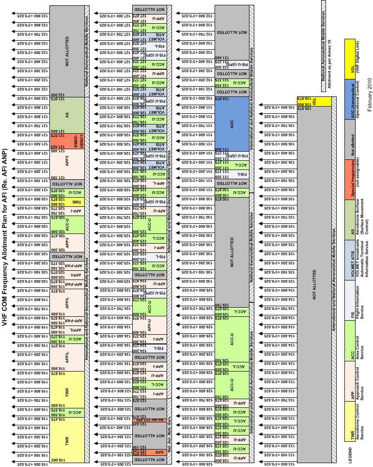
59 Page 56
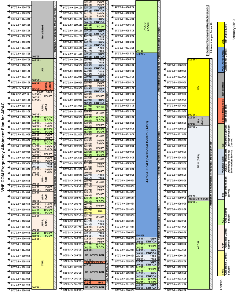
60 Page 57

61 Page 58
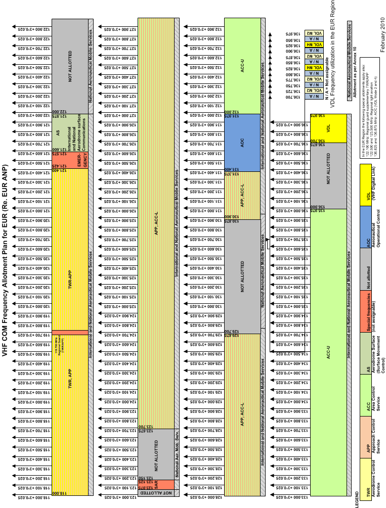
62 Page 59
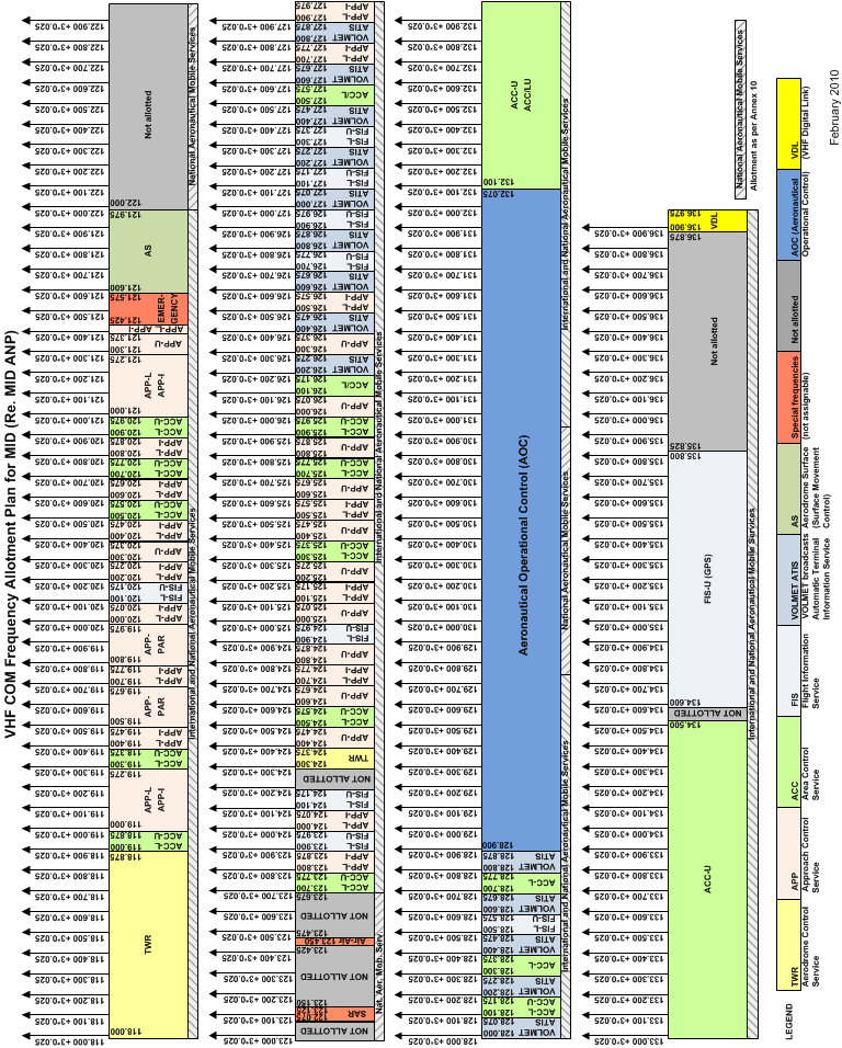
63 Page 60
CIVIL AVIATION REQUIREMENTS SECTION 9 AIR SPACE AND AIR TRAFFIC MANAGEMENT SERIES 'D' PART VI
 GOVERNMENT OF INDIA OFFICE OF DIRECTOR GENERAL OF CIVIL AVIATION TECHNICAL CENTRE, OPP SAFDARJANG AIRPORT, NEW DELHI CIVIL AVIATION REQUIREMENTS SECTION 9 AIR SPACE AND AIR TRAFFIC MANAGEMENT SERIES 'D'
How To Use Vhf For Radio Communication
 Air Navigation Order (ANO) For Aeronautical Radio frequency Spectrum Utilization ANO (COM) A.5 FIRST EDITION FEBRUARY 2009 CIVIL AVIATION AUTHORITY BANGLADESH Civil Aviation Authority, Bangladesh ANO
SHARING BETWEEN TERRESTRIAL FLIGHT TELEPHONE SYSTEM (TFTS) AND RADIO ASTRONOMY IN THE 1.6 GHz BAND. Paris, May 1992
 AND RADIO ASTRONOMY IN THE 1.6 GHz BAND. Paris, May 1992") European Radiocommunications Committee (ERC) within the European Conference of Postal and Telecommunications Administrations (CEPT) SHARING BETWEEN TERRESTRIAL FLIGHT TELEPHONE SYSTEM (TFTS) AND RADIO
European Radiocommunications Committee (ERC) within the European Conference of Postal and Telecommunications Administrations (CEPT) SHARING BETWEEN TERRESTRIAL FLIGHT TELEPHONE SYSTEM (TFTS) AND RADIO
Compatibility between the soundbroadcasting service in the band. of about 87-108 MHz and the aeronautical services in the band 108-137 MHz
 Recommendation ITU-R SM.1009-1 (10/1995) Compatibility between the soundbroadcasting service in the band of about 87-108 MHz and the aeronautical services in the band 108-137 MHz SM Series Spectrum management
AN INTRODUCTION TO TELEMETRY PART 1: TELEMETRY BASICS
 AN INTRODUCTION TO TELEMETRY PART 1: TELEMETRY BASICS Telemetry is defined as the sensing and measuring of information at some remote location and then transmitting that information to a central or host
COMPATIBILITY AND SHARING ANALYSIS BETWEEN DVB T AND RADIO MICROPHONES IN BANDS IV AND V
 European Radiocommunications Committee (ERC) within the European Conference of Postal and Telecommunications Administrations (CEPT) COMPATIBILITY AND SHARING ANALYSIS BETWEEN DVB T AND RADIO MICROPHONES
EE4367 Telecom. Switching & Transmission. Prof. Murat Torlak
 Path Loss Radio Wave Propagation The wireless radio channel puts fundamental limitations to the performance of wireless communications systems Radio channels are extremely random, and are not easily analyzed
SARPS about Emergency frequency. 12 May 2015
 SARPS about Emergency frequency 12 May 2015 Annex 6 3.1.5 If an emergency situation which endangers the safety of the aeroplane or persons becomes known first to the flight operations officer/flight dispatcher,
Electronic Communications Committee (ECC) within the Conference of Postal and Telecommunications Administrations (CEPT)
 within the Conference of Postal and Telecommunications Administrations (CEPT)") Page 1 Electronic Communications Committee (ECC) within the Conference of Postal and Telecommunications Administrations (CEPT) ECC RECOMMENDATION (05)08 (replacing recommendations T/R 20-08 and 22-07)
Page 1 Electronic Communications Committee (ECC) within the Conference of Postal and Telecommunications Administrations (CEPT) ECC RECOMMENDATION (05)08 (replacing recommendations T/R 20-08 and 22-07)
Antennas & Propagation. CS 6710 Spring 2010 Rajmohan Rajaraman
 Antennas & Propagation CS 6710 Spring 2010 Rajmohan Rajaraman Introduction An antenna is an electrical conductor or system of conductors o Transmission - radiates electromagnetic energy into space o Reception
PROTECTION OF THE BROADCASTING SERVICE FROM BROADCASTING SATELLITE SERVICE TRANSMISSIONS IN THE BAND 620 790 MHz
 Electronic Communications Committee (ECC) within the European Conference of Postal and Telecommunications Administrations (CEPT) PROTECTION OF THE BROADCASTING SERVICE FROM BROADCASTING SATELLITE SERVICE
FREQUENCY ASSIGNMENT REQUIREMENTS FOR THE LAND MOBILE SERVICE
 RALI : LM 8 DATE OF EFFECT : 23/09/2015 Radiocommunications Assignment and Licensing Instruction FREQUENCY ASSIGNMENT REQUIREMENTS FOR THE LAND MOBILE SERVICE AUSTRALIAN COMMUNICATIONS AND MEDIA AUTHORITY
This Antenna Basics reference guide includes basic information about antenna types, how antennas work, gain, and some installation examples.
 Antenna Basics This Antenna Basics reference guide includes basic information about antenna types, how antennas work, gain, and some installation examples. What Do Antennas Do? Antennas transmit radio
RECOMMENDATION ITU-R P.1546-1. Method for point-to-area predictions for terrestrial services in the frequency range 30 MHz to 3 000 MHz
 Rec. ITU-R P.546- RECOMMENDATION ITU-R P.546- Method for point-to-area predictions for terrestrial services in the frequency range 30 MHz to 3 000 MHz (200-2003) The ITU Radiocommunication Assembly, considering
RECOMMENDATION ITU-R F.1113. (Question ITU-R 157/9) b) that systems using this mode of propagation are already in service for burst data transmission,
 b) that systems using this mode of propagation are already in service for burst data transmission,") Rec. ITU-R F.1113 1 RECOMMENDATION ITU-R F.1113 RADIO SYSTEMS EMPLOYING METEOR-BURST PROPAGATION (Question ITU-R 157/9) (1994) Rec. ITU-R F.1113 The ITU Radiocommunication Assembly, considering a) that
Rec. ITU-R F.1113 1 RECOMMENDATION ITU-R F.1113 RADIO SYSTEMS EMPLOYING METEOR-BURST PROPAGATION (Question ITU-R 157/9) (1994) Rec. ITU-R F.1113 The ITU Radiocommunication Assembly, considering a) that
CHAPTER 4. Electromagnetic Spectrum
 ELEC4504 Avionics Systems 9 CHAPTER 4. Electromagnetic Spectrum 4.1. Electromagnetic (EM) Waves In free space (or the atmosphere) the electric field is perpendicular to the magnetic field and both are
AIP GEN 3.4-1 GREECE 19 SEP 2013 GEN 3.4 COMMUNICATION SERVICES (COM)
") AIP GEN 3.4-1 GREECE 19 SEP 2013 GEN 3.4 COMMUNICATION SERVICES (COM) 3.4.1 Responsible service 3.4.1.1 The Hellenic Civil Aviation Authority is responsible for the provision of aeronautical telecommunication
AIP GEN 3.4-1 GREECE 19 SEP 2013 GEN 3.4 COMMUNICATION SERVICES (COM) 3.4.1 Responsible service 3.4.1.1 The Hellenic Civil Aviation Authority is responsible for the provision of aeronautical telecommunication
Compatibility of amateur service stations with existing services in the range 415-526.5 khz
 Report ITU-R M.2203 (11/2010) Compatibility of amateur service stations with existing services in the range 415-526.5 khz M Series Mobile, radiodetermination, amateur and related satellite services ii
RECOMMENDATION ITU-R S.524-5. (Questions ITU-R 48/4 and ITU-R 70/4)
") Rec. ITU-R S.524-5 1 RECOMMENDATION ITU-R S.524-5 MAXIMUM PERMISSIBLE LEVELS OF OFF-AXIS e.i.r.p. DENSITY FROM EARTH STATIONS IN THE FIXED-SATELLITE SERVICE TRANSMITTING IN THE 6 AND 14 GHz FREQUENCY BANDS
Rec. ITU-R S.524-5 1 RECOMMENDATION ITU-R S.524-5 MAXIMUM PERMISSIBLE LEVELS OF OFF-AXIS e.i.r.p. DENSITY FROM EARTH STATIONS IN THE FIXED-SATELLITE SERVICE TRANSMITTING IN THE 6 AND 14 GHz FREQUENCY BANDS
Avaya WLAN 9100 External Antennas for use with the WAO-9122 Access Point
 Avaya WLAN 9100 External Antennas for use with the WAO-9122 Access Point Overview To optimize the overall performance of a WLAN in an outdoor deployment it is important to understand how to maximize coverage
Characteristics of terrestrial IMT-Advanced systems for frequency sharing/ interference analyses
 Report ITU-R M.2292-0 (12/2013) Characteristics of terrestrial IMT-Advanced systems for frequency sharing/ interference analyses M Series Mobile, radiodetermination, amateur and related satellite services
How To Protect Your Cell Phone From Interference From Power Lines And Airplanes
 A Sampling of Current Issues: BPL, >275 GHz, & Airborne Cell Phones Andrew Clegg National Science Foundation Broadband over Power Lines The provision of consumer broadband internet access using existing
MODELING FOR SPECTRUM CONGESTION ANALYSIS OF AIR-TO-GROUND VOICE COMMUNICATIONS IN CHINA
 MODELING FOR SPECTRUM CONGESTION ANALYSIS OF AIR-TO-GROUND VOICE COMMUNICATIONS IN CHINA Han Zhou, Haoyu Xu, Jiangnan Bian, Joint Research Laboratory for Aviation Connectivity Technologies, Shanghai Advanced
Introduction to RF Engineering. Andrew CLEGG
 Introduction to RF Engineering Andrew CLEGG 1 Comparing the Lingo Radio Astronomers Speak a Unique Vernacular We are receiving interference from your transmitter at a level of 10 janskys What the ^#$&
GSM frequency planning
 GSM frequency planning Band : 890-915 and 935-960 MHz Channel spacing: 200 khz (but signal bandwidth = 400 khz) Absolute Radio Frequency Channel Number (ARFCN) lower band: upper band: F l (n) = 890.2 +
Antenna Deployment Technical Brief
 ProCurve Networking Antenna Deployment Technical Brief Introduction... 2 Antenna types... 2 Omni directional antennas... 2 Directional antennas... 2 Diversity antennas... 3 High gain directional antennas...
An Introduction to Microwave Radio Link Design
 An Introduction to Microwave Radio Link Design Table of Contents 1 Introduction... 3 2 Radio Link Engineering main steps... 3 2.1 Make Path profile... 3 2.2 Calculate Free Space Loss (FSL)... 4 2.3 Calculate
Omni Antenna vs. Directional Antenna
 Omni Antenna vs. Directional Antenna Document ID: 82068 Contents Introduction Prerequisites Requirements Components Used Conventions Basic Definitions and Antenna Concepts Indoor Effects Omni Antenna Pros
FURTHER READING: As a preview for further reading, the following reference has been provided from the pages of the book below:
 FURTHER READING: As a preview for further reading, the following reference has been provided from the pages of the book below: Title: Cellular/PCS Management Author: Paul Beddel Publisher: McGraw-Hill
AN1200.04. Application Note: FCC Regulations for ISM Band Devices: 902-928 MHz. FCC Regulations for ISM Band Devices: 902-928 MHz
 AN1200.04 Application Note: FCC Regulations for ISM Band Devices: Copyright Semtech 2006 1 of 15 www.semtech.com 1 Table of Contents 1 Table of Contents...2 1.1 Index of Figures...2 1.2 Index of Tables...2
102 26-m Antenna Subnet Telecommunications Interfaces
 DSMS Telecommunications Link Design Handbook 26-m Antenna Subnet Telecommunications Interfaces Effective November 30, 2000 Document Owner: Approved by: Released by: [Signature on file in TMOD Library]
ECC/DEC/(04)08 ELECTRONIC COMMUNICATIONS COMMITTEE
08 ELECTRONIC COMMUNICATIONS COMMITTEE") ELECTRONIC COMMUNICATIONS COMMITTEE ECC Decision of 09 July 2004 on the harmonised use of the 5 GHz frequency bands for the implementation of Wireless Access Systems including Radio Local Area Networks
ELECTRONIC COMMUNICATIONS COMMITTEE ECC Decision of 09 July 2004 on the harmonised use of the 5 GHz frequency bands for the implementation of Wireless Access Systems including Radio Local Area Networks
Antenna Properties and their impact on Wireless System Performance. Dr. Steven R. Best. Cushcraft Corporation 48 Perimeter Road Manchester, NH 03013
 Antenna Properties and their impact on Wireless System Performance Dr. Steven R. Best Cushcraft Corporation 48 Perimeter Road Manchester, NH 03013 Phone (603) 627-7877 FAX: (603) 627-1764 Email: sbest@cushcraft.com
An Algorithm for Automatic Base Station Placement in Cellular Network Deployment
 An Algorithm for Automatic Base Station Placement in Cellular Network Deployment István Törős and Péter Fazekas High Speed Networks Laboratory Dept. of Telecommunications, Budapest University of Technology
Electromagnetic radiation exposure: assessment against ACA mandated limits
 Electromagnetic radiation exposure: assessment against ACA mandated limits General radio services (operating above 0 MHz) (Edition May 0) Disclaimer Unless otherwise specified, the information contained
How To Write A National Radio Plan
 NATIONAL FREQUENCY PLAN IN THE KINGDOM OF SAUDI ARABIA CONTENTS ARTICLE 1: TERMS ARTICLE:2 STRUCTURE OF THE NATIONAL FREQUENCY PLAN 1. Description of the National Table 2 Categories of Services 3 Spectrum
COMPATIBILITY STUDY FOR UMTS OPERATING WITHIN THE GSM 900 AND GSM 1800 FREQUENCY BANDS
 Electronic Communications Committee (ECC) within the European Conference of Postal and Telecommunications Administrations (CEPT) COMPATIBILITY STUDY FOR UMTS OPERATING WITHIN THE GSM 900 AND GSM 1800 FREQUENCY
GHANA NATIONAL FREQUENCY ALLOCATION TABLE 2013
 GHANA NATIONAL FREQUENCY ALLOCATION TABLE 2013 Table of Contents INTRODUCTION... 3 TERMS AND DEFINITIONS... 4 STRUCTURE OF THE NATIONAL TABLE OF FREQUENCY ALLOCATIONS... 10 TABLE OF FREQUENCY ALLOCATION...
A. Jraifi, R. A. Laamara, A. Belhaj, and E. H. Saidi Lab/UFR-groupe Canal Propagation Radio PHE, Faculté des Sciences, Rabat, Morocco
 Progress In Electromagnetics Research C, Vol. 12, 15 25, 2010 A PROPOSAL SOLUTION FOR INTERFERENCE INTER-OPERATORS A. Jraifi, R. A. Laamara, A. Belhaj, and E. H. Saidi Lab/UFR-groupe Canal Propagation
Brief on xdsl interference
 Brief on xdsl interference Prepared by C. Szabo - EUROCONTROL 1. Introduction The xdsl acronym includes the following Digital Subscriber Lines (DSL): - High Data-Rate Digital Subscriber Line (HDSL) - Single-Line
is the power reference: Specifically, power in db is represented by the following equation, where P0 P db = 10 log 10
 RF Basics - Part 1 This is the first article in the multi-part series on RF Basics. We start the series by reviewing some basic RF concepts: Decibels (db), Antenna Gain, Free-space RF Propagation, RF Attenuation,
Understanding Range for RF Devices
 Understanding Range for RF Devices October 2012 White Paper Understanding how environmental factors can affect range is one of the key aspects to deploying a radio frequency (RF) solution. This paper will
International Civil Aviation Organization. The Third Meeting of the Regional ATM Contingency Plan Task Force (RACP/TF/3)
") International Civil Aviation Organization RACP/TF/3 WP06 12-15/11/2013 The Third Meeting of the Regional ATM Contingency Plan Task Force (RACP/TF/3) Bangkok, Thailand, 12 15 November 2013 Agenda Item 4:
International Civil Aviation Organization RACP/TF/3 WP06 12-15/11/2013 The Third Meeting of the Regional ATM Contingency Plan Task Force (RACP/TF/3) Bangkok, Thailand, 12 15 November 2013 Agenda Item 4:
Isolation between antennas of IMT base stations in the land mobile service
 Report ITU-R M.44 (11/011) Isolation between antennas of IMT base stations in the land mobile service M Series Mobile, radiodetermination, amateur and related satellite services ii Rep. ITU-R M.44 Foreword
Planning Terrestrial Radio Networks
 Planning Terrestrial Radio Networks Lab Exercise Manual IK2500 - Radio Communication, Basic Course September 23, 2008 Short Summary The scope of this lab is to help students to develop basic skills in
Application Note AN-00126
 Considerations for Operation within the 902-928MHz Band Application Note AN-00126 Introduction This application note is designed to give the reader a basic understanding of the legal and technical considerations
Environmental Monitoring: Guide to Selecting Wireless Communication Solutions
 Environmental Monitoring: Guide to Selecting Wireless Communication Solutions By: Scott South Published in WaterWorld, January 2005 (Page 48) Rapidly growing demands for information and increased productivity
INTRODUCTION TO COMMUNICATION SYSTEMS AND TRANSMISSION MEDIA
 COMM.ENG INTRODUCTION TO COMMUNICATION SYSTEMS AND TRANSMISSION MEDIA 9/6/2014 LECTURES 1 Objectives To give a background on Communication system components and channels (media) A distinction between analogue
5. ANTENNA TYPES. Figure 5. The vertical dipole and its electromagnetic equivalent, the vertical monopole
 Antennas can be classified in several ways. One way is the frequency band of operation. Others include physical structure and electrical/electromagnetic design. The antennas commonly used for LMR both
How To Get A Signal From Samoa
 1 Government of Samoa Office of the Regulator Private Bag, Apia, Samoa NATIONAL FREQUENCY ALLOCATION TABLE (This document is part of the National Spectrum Plan) Prepare by the Office of the Regulator 2
MANAGEMENT OF BI-DIRECTIONAL AMPLIFIERS IN THE LAND MOBILE SERVICE IN THE FREQUENCY RANGE 29.7 MHz TO 520 MHz
 RALI : LM 6 DATE OF EFFECT :.13/03/96 Sequence Number :.66 Radiocommunications Assignment and Licensing Instruction MANAGEMENT OF BI-DIRECTIONAL AMPLIFIERS IN THE LAND MOBILE SERVICE IN THE FREQUENCY RANGE
DVB-T and Wireless Microphone Exclusion Area Computation Through Interference Analysis
 SE43(11)Info 12 DVB-T and Wireless Microphone Exclusion Area Computation Through Interference Analysis Rogério Dionísio Instituto de Telecomunicações - Portugal 11th SE43 meeting, 19 September 2011 Page
Electromagnetic radiation exposure: assessment against ACA mandated limits
 Electromagnetic radiation exposure: assessment against ACA mandated limits Paging services (Edition May 2002) Disclaimer Unless otherwise specified, the information contained in these guidelines is intended
SYSTEM GLOBAL NAVIGATION SATELLITE SYSTEM LANDING TECHNOLOGY/PRODUCT DEVELOPMENT
 GLOBAL NAVIGATION SATELLITE SYSTEM LANDING SYSTEM The aviation industry is developing a new positioning and landing system based on the Global Navigation Satellite System (GNSS). The GNSS landing system
Aircraft Tracking & Flight Data Recovery
 Airframer view Presented by: Claude Pichavant Aircraft Tracking & Flight Data Recovery Aircraft Tracking & Flight Data Recovery Airbus has contributed to the Aircraft Tracking Task Force (ATTF), to the
RF Path Loss & Transmission Distance Calculations
 RF Path Loss & Transmission Distance Calculations By Walter Debus Director of Engineering Axonn, LLC Technical Memorandum August 4, 2006 INTRODUCTION DOC# 8545-0003-01 For radio transmission systems that
COMMUNICATIONS AND MULTIMEDIA ACT 1998 NOTIFICATION OF ISSUANCE OF CLASS ASSIGNMENTS
 COMMUNICATIONS AND MULTIMEDIA ACT 1998 NOTIFICATION OF ISSUANCE OF CLASS ASSIGNMENTS IN exercise of the powers conferred by section 169 of the Communications and Multimedia Act 1998 [Act 588], the Commission
Radio Physics for Wireless Devices and Networking. The Radio Physics of WiFi. By Ron Vigneri
 Radio Physics for Wireless Devices and Networking By Ron Vigneri The Radio Physics of WiFi The standard for wireless LANs (WLANs) was completed in 1997 with the release of the IEEE 802.11 specification
Design and Certification of ASH Radio Systems for Japan
 Design and Certification of ASH Radio Systems for Japan RFM s second-generation ASH radio hybrids are being used in a wide variety of applications in Japan, operating under the Japanese BIJAKU radio regulations.
COMPATIBILITY BETWEEN CERTAIN RADIOCOMMUNICATIONS SYSTEMS OPERATING IN ADJACENT BANDS EVALUATION OF DECT / GSM 1800 COMPATIBILITY
 European Radiocommunications Committee (ERC) within the European Conference of Postal and Telecommunications Administrations (CEPT) COMPATIBILITY BETWEEN CERTAIN RADIOCOMMUNICATIONS SYSTEMS OPERATING IN
ABHELSINKI UNIVERSITY OF TECHNOLOGY
 Basic of Propagation Theory S-72.333 Physical Layer Methods in Wireless Communication Systems Fabio Belloni Helsinki University of Technology Signal Processing Laboratory fbelloni@wooster.hut.fi 23 November
DT3: RF On/Off Remote Control Technology. Rodney Singleton Joe Larsen Luis Garcia Rafael Ocampo Mike Moulton Eric Hatch
 DT3: RF On/Off Remote Control Technology Rodney Singleton Joe Larsen Luis Garcia Rafael Ocampo Mike Moulton Eric Hatch Agenda Radio Frequency Overview Frequency Selection Signals Methods Modulation Methods
NATIONAL TABLE OF FREQUENCY ALLOCATIONS
 State Commission on Radio Frequencies of the Republic of Moldova NATIONAL TABLE OF FREQUENCY ALLOCATIONS Adopted by Decision of the State Commission on Radio Frequencies of the Republic of Moldova no.
COMMISSION OF THE EUROPEAN COMMUNITIES. Draft COMMISSION DECISION
 COMMISSION OF THE EUROPEAN COMMUNITIES Brussels, C (2008) Draft COMMISSION DECISION of [ ] on harmonised conditions of spectrum use for the operation of mobile communication services on aircraft (MCA services)
Improved satellite detection of AIS
 Report ITU-R M.2169 (12/2009) Improved satellite detection of AIS M Series Mobile, radiodetermination, amateur and related satellites services ii Rep. ITU-R M.2169 Foreword The role of the Radiocommunication
: Coaxial Cable Television Interference to Aviation Systems EXECUTIVE SUMMARY
 EUROCONTROL DIS/COM/SD Date : 15.03.2001 Subject Origin : Coaxial Cable Television Interference to Aviation Systems : EUROCONTROL EXECUTIVE SUMMARY This paper provides a brief on the impact of cable television
UNITED STATES OF AMERICA DRAFT PROPOSALS FOR THE WORK OF THE CONFERENCE
 UNITED STATES OF AMERICA DRAFT PROPOSALS FOR THE WORK OF THE CONFERENCE Agenda Item 10: to recommend to the Council, items for inclusion in the agenda for the next WRC, and to give its views on the preliminary
THE EUROPEAN TABLE OF FREQUENCY ALLOCATIONS AND APPLICATIONS IN THE FREQUENCY RANGE 8.3 khz to 3000 GHz (ECA TABLE)
") Electronic Communications Committee (ECC) within the European Conference of Postal and Telecommunications Administrations (CEPT) THE EUROPEAN TABLE OF FREQUENCY ALLOCATIONS AND APPLICATIONS IN THE FREQUENCY
Electronic Communications Committee (ECC) within the European Conference of Postal and Telecommunications Administrations (CEPT) THE EUROPEAN TABLE OF FREQUENCY ALLOCATIONS AND APPLICATIONS IN THE FREQUENCY
RX-AM4SF Receiver. Pin-out. Connections
 RX-AM4SF Receiver The super-heterodyne receiver RX-AM4SF can provide a RSSI output indicating the amplitude of the received signal: this output can be used to create a field-strength meter capable to indicate
HUMAN EXPOSURE TO EMR: ASSESSMENT OF AMATEUR RADIO STATIONS FOR COMPLIANCE WITH ACA REQUIREMENTS
 HUMAN EXPOSURE TO EMR: ASSESSMENT OF AMATEUR RADIO STATIONS FOR COMPLIANCE WITH ACA REQUIREMENTS May 2005 Version 2.0 PO Box 78 BELCONNEN ACT 2616 Telephone (02) 6219 5555 Facsimile (02) 6219 5353 www.aca.gov.au
Bespoke licence fees for aeronautical VHF communications frequencies A statement
 - Bespoke licence fees for aeronautical VHF communications frequencies A statement Statement Publication date: 7 June 2011 Contents Section 1 Summary 2 Introduction 3 Summary of responses 4 Conclusions
MICROWAVE ANTENNA PATTERN WITH DIFFERENT PARAMETER EVALUATION IN MOBILE ENVIRONMENT
 www.arpapress.com/volumes/vol9issue1/ijrras_9_1_07.pdf MICROWAVE ANTENNA PATTERN WITH DIFFERENT PARAMETER EVALUATION IN MOBILE ENVIRONMENT 1,* D.S. Ramkiran, 2 A.RamaKrishna, 1 Ch.Radhika & 1 B.T.P.Madhav
The Application of Land Use/ Land Cover (Clutter) Data to Wireless Communication System Design
 Data to Wireless Communication System Design") Technology White Paper The Application of Land Use/ Land Cover (Clutter) Data to Wireless Communication System Design The Power of Planning 1 Harry Anderson, Ted Hicks, Jody Kirtner EDX Wireless, LLC Eugene,
Technology White Paper The Application of Land Use/ Land Cover (Clutter) Data to Wireless Communication System Design The Power of Planning 1 Harry Anderson, Ted Hicks, Jody Kirtner EDX Wireless, LLC Eugene,
Rec. ITU-R F.699-5 1 RECOMMENDATION ITU-R F.699-5 *
 Rec. ITU-R F.699-5 1 RECOMMENATION ITU-R F.699-5 * REFERENCE RAIATION PATTERNS FOR LINE-OF-SIGHT RAIO-RELAY SYSTEM ANTENNAS FOR USE IN COORINATION STUIES AN INTERFERENCE ASSESSMENT IN THE FREQUENCY RANGE
COMPATIBILITY STUDIES BETWEEN GROUND BASED SYNTHETIC APERTURE RADAR (GBSAR) AND EXISTING SERVICES IN THE RANGE 17.1 GHz TO 17.
 AND EXISTING SERVICES IN THE RANGE 17.1 GHz TO 17.") Electronic Communications Committee (ECC) within the European Conference of Postal and Telecommunications Administrations (CEPT) COMPATIBILITY STUDIES BETWEEN GROUND BASED SYNTHETIC APERTURE RADAR (GBSAR)
Electronic Communications Committee (ECC) within the European Conference of Postal and Telecommunications Administrations (CEPT) COMPATIBILITY STUDIES BETWEEN GROUND BASED SYNTHETIC APERTURE RADAR (GBSAR)
BASIS for August 1996 REGULATION
 DRAFT TECHNICAL pr TBR 029 BASIS for August 1996 REGULATION Source: ETSI TC-SES Reference: DTBR/SES-00007 ICS: 33.060.30 Key words: broadcasting, earth station, radio, satellite, TV, TVRO, type approval
Measurement of RF Emissions from a Final Coat Electronics Corrosion Module
 Engineering Test Report No. 37802-02 Rev. A Measurement of RF Emissions from a Final Coat Electronics Corrosion Module For : Canadian Auto Preservation, Inc. 390 Bradwick Drive Concord, Ontario CANADA
Wireless Public Address Systems (WPAS) Licensing. Information Briefing Westbury Hotel, Dublin 26 th July 2006
 Licensing. Information Briefing Westbury Hotel, Dublin 26 th July 2006") Wireless Public Address Systems (WPAS) Licensing Information Briefing Westbury Hotel, Dublin 26 th July 2006 27/07/2006 2 Agenda WPAS: Wireless Public Address System 1. Background to WPAS Licensing Scheme
Wireless Public Address Systems (WPAS) Licensing Information Briefing Westbury Hotel, Dublin 26 th July 2006 27/07/2006 2 Agenda WPAS: Wireless Public Address System 1. Background to WPAS Licensing Scheme
BASIS for April 1997 REGULATION
 FINAL DRAFT TECHNICAL pr TBR 029 BASIS for April 1997 REGULATION Source: ETSI TC-SES Reference: DTBR/SES-00007 ICS: 33.020 Key words: Satellite, earth station, TV, TVRO, type approval Satellite Earth Stations
Part I: Wireless System Characteristics
 Part I: Wireless System Characteristics Smart grid technology holds great promise of cleaner air, more efficient power, and lower greenhouse gas emissions. In a smart grid system, the system itself will
Selecting Receiving Antennas for Radio Tracking
 Selecting Receiving Antennas for Radio Tracking Larry B Kuechle, Advanced Telemetry Systems, Inc. Isanti, Minnesota 55040 lkuechle@atstrack.com The receiving antenna is an integral part of any radio location
CABLES CABLES. Application note. Link Budget
 CABLES CABLES radiating Link Budget 3. 1. LINK BUDGET The basic elements to calculate a link budget can be illustrated by considering the example shown in Figure 4. It involves a GSM 900 radio coverage
RECOMMENDATION ITU-R BS.704 *, ** Characteristics of FM sound broadcasting reference receivers for planning purposes
 Rec. ITU-R BS.704 1 RECOMMENDATION ITU-R BS.704 *, ** Characteristics of FM sound broadcasting reference receivers for planning purposes (1990) The ITU Radiocommunication Assembly, considering a) that
Amplifier for Small Magnetic and Electric Wideband Receiving Antennas (model AAA-1B)
") Amplifier for Small Magnetic and Electric Wideband Receiving Antennas (model AAA-1B) 1. Description and Specifications Contents 1.1 Description 1.2 1.2 Specifications 1.3 1.3 Tested parameters in production
Amplifier for Small Magnetic and Electric Wideband Receiving Antennas (model AAA-1B) 1. Description and Specifications Contents 1.1 Description 1.2 1.2 Specifications 1.3 1.3 Tested parameters in production
ETSI EN 302 774 V1.2.1 (2012-02)
") EN 302 774 V1.2.1 (2012-02) Harmonized European Standard Broadband Wireless Access Systems (BWA) in the 3 400 MHz to 3 800 MHz frequency band; Base Stations; Harmonized EN covering the essential requirements
EN 302 774 V1.2.1 (2012-02) Harmonized European Standard Broadband Wireless Access Systems (BWA) in the 3 400 MHz to 3 800 MHz frequency band; Base Stations; Harmonized EN covering the essential requirements
Pillbox Antenna for 5.6 GHz Band Dragoslav Dobričić, YU1AW dragan@antennex.com
 Pillbox Antenna for 5.6 GHz Band Dragoslav Dobričić, YU1AW dragan@antennex.com Introduction The pillbox or cheese antenna is made of two parallel plates which are connected to the narrow strip of parabolic
T = 1 f. Phase. Measure of relative position in time within a single period of a signal For a periodic signal f(t), phase is fractional part t p
, phase is fractional part t p") Data Transmission Concepts and terminology Transmission terminology Transmission from transmitter to receiver goes over some transmission medium using electromagnetic waves Guided media. Waves are guided
Data Transmission Concepts and terminology Transmission terminology Transmission from transmitter to receiver goes over some transmission medium using electromagnetic waves Guided media. Waves are guided
EMC Standards: Standards of good EMC engineering
 Electromagnetic Compatibility (EMC) IEEE Definition Origin, control, and measurement of electromagnetic effects on electronic and biologic systems. IEEE EMC Society Areas of Interest EMC Standards: Standards
Amplification of the Radiation from Two Collocated Cellular System Antennas by the Ground Wave of an AM Broadcast Station
 Amplification of the Radiation from Two Collocated Cellular System Antennas by the Ground Wave of an AM Broadcast Station Dr. Bill P. Curry EMSciTek Consulting Co., W101 McCarron Road Glen Ellyn, IL 60137,
RECOMMENDATION ITU-R SM.1792. Measuring sideband emissions of T-DAB and DVB-T transmitters for monitoring purposes
 Rec. ITU-R SM.1792 1 RECOMMENDATION ITU-R SM.1792 Measuring sideband emissions of T-DAB and DVB-T transmitters for monitoring purposes (2007) Scope This Recommendation provides guidance to measurement
ACRS 2.0 User Manual 1
 ACRS 2.0 User Manual 1 FCC Regulatory Information This device complies with part 15 of the FCC Rules. Operation is subject to the following two conditions: (1) This device may not cause harmful interference,
Coaxial Cable Feeder Influence on Yagi Antenna Dragoslav Dobričić, YU1AW dragan@antennex.com
 Coaxial Cable Feeder Influence on Yagi Antenna Dragoslav Dobričić, YU1AW dragan@antennex.com Introduction o far, in several previous articles [1, 2, 3], we investigated how boom radius and its S distance
RECOMMENDATION ITU-R M.1082-1*, **
 Rec. ITU-R M.1082-1 1 RECOMMENDATION ITU-R M.1082-1*, ** INTERNATIONAL MARITIME MF/HF RADIOTELEPHONE SYSTEM WITH AUTOMATIC FACILITIES BASED ON DIGITAL SELECTIVE CALLING SIGNALLING FORMAT Rec. ITU-R M.1082-1
Spectrum and Power Measurements Using the E6474A Wireless Network Optimization Platform
 Application Note Spectrum and Power Measurements Using the E6474A Wireless Network Optimization Platform By: Richard Komar Introduction With the rapid development of wireless technologies, it has become
Downlink Performance of WiMAX Broadband from High Altitude Platform and Terrestrial Deployments sharing a common 3.5GHz band
 Downlink Performance of WiMAX Broadband from igh Altitude Platform and Terrestrial Deployments sharing a common 3.5Gz band Z. Yang, D. Grace, P. D. Mitchell Communications Research Group, Department of
System Design in Wireless Communication. Ali Khawaja
 System Design in Wireless Communication Ali Khawaja University of Texas at Dallas December 6, 1999 1 Abstract This paper deals with the micro and macro aspects of a wireless system design. With the growing
1 Multi-channel frequency division multiplex frequency modulation (FDM-FM) emissions
 emissions") Rec. ITU-R SM.853-1 1 RECOMMENDATION ITU-R SM.853-1 NECESSARY BANDWIDTH (Question ITU-R 77/1) Rec. ITU-R SM.853-1 (1992-1997) The ITU Radiocommunication Assembly, considering a) that the concept of necessary
Rec. ITU-R SM.853-1 1 RECOMMENDATION ITU-R SM.853-1 NECESSARY BANDWIDTH (Question ITU-R 77/1) Rec. ITU-R SM.853-1 (1992-1997) The ITU Radiocommunication Assembly, considering a) that the concept of necessary
UK Interface Requirement 2063
 UK Interface Requirement 2063 Ground based secondary surveillance radar site monitor at aeronautical stations of the aeronautical radionavigation service. Publication date: Feb 2006 Version: 1.0 98/34/EC
Transport Spectrum Tune-Up 2009. Aviation Spectrum Issues. Eddy D Amico, RF Spectrum Manager Airservices Australia. November 2009
 Transport Spectrum Tune-Up 2009 Aviation Spectrum Issues Eddy D Amico, RF Spectrum Manager Airservices Australia November 2009 Overview Background Importance of radio spectrum for aviation Communications
Radio Network Planning Tools Basics, Practical Examples & Demonstration on NGN Network Planning Part I
 Radio Network Planning Tools Basics, Practical Examples & Demonstration on NGN Network Planning Part I Roland Götz LS telcom AG Regional Seminar on evolving network infrastructures to NGN and related Planning