00 Publication number:
|
|
|
- Felix Wilson
- 8 years ago
- Views:
Transcription
1 Europaisches Patentamt European Patent Office Office europeen des brevets 00 Publication number: B1 EUROPEAN PATENT SPECIFICATION Date of publication of patent specification: Int. CI.5: H04Q 11/02, H04B 10/00, H04J 14/00, H04L 12/54, Application number: H04L Date of filing: Switching techniques for FDM communication systems. Priority: US Date of publication of application: Bulletin 88/09 Publication of the grant of the patent: Bulletin 93/30 Designated Contracting States: DE FR GB NL SE References cited: EP-A WO-A-84/04015 DE-A FR-A US-A Proprietor: AMERICAN TELEPHONE AND TELEGRAPH COMPANY 550 Madison Avenue New York, NY Inventor: Darcie, Thomas Edward 4 Fox Drive Hazlet New Jersey 07730(US) Inventor: Gans, Michael James 39 River Avenue Monmouth Beach New Jersey 07750(US) Representative: Johnston, Kenneth Graham et al AT&T (UK) Ltd. 5 Mornington Road Woodford Green Essex, IG8 OTU (GB) 00 PATENT ABSTRACTS OF JAPAN, vol. 10, no. 108 (E-398)[2165], 23rd April 1986 & JP-A m CM CL LU Note: Within nine months from the publication of the mention of the grant of the European patent, any person may give notice to the European Patent Office of opposition to the European patent granted. Notice of opposition shall be filed in a written reasoned statement. It shall not be deemed to have been filed until the opposition fee has been paid (Art. 99(1) European patent convention). Rank Xerox (UK) Business Services (3. 10/3.6/3.3. 1)

2 EP B1 Description The present invention relates to a Frequency Division Multiplexed (FDM) switching technique for use in optical or radio communication systems such as, for example, Local Area Networks (LANs). More particularly, each system user's transmitter and receiver is fixed or selectively assigned to a predetermined unique frequency channel. A central station demodulates all transmitted signals received by that station to baseband and determines from an address portion of each message to which receiver the message is to be sent. Each baseband signal can be hard-wired to its transmitted oscillator which is frequency tuned by the received address portion to the unique frequency channel of the desired receiver. Description of the Prior Art Every type of communication system interconnecting more than two users depends on some form of switching to efficiently route information among the various users. With Frequency-Division- Multiplexing (FDM), various techniques for centralized and non-centralized routing have been used. One routing technique is to provide a switching array which switches multiple signals at either baseband or at an intermediate frequency (IF) which were received and/or are to be transmitted as FDM signals over a transmission medium. In this regard see, for example, US-A issued to K. Panzer on May 3, 1983, or the article by R. B. Hawkins et al. in Sixth International Conference On Digital Satellite Communications, September 1983, Phoenix, Arizona, at pages VI Similarly, the article by R. I. MacDonald et al. in Electronic Letters, Vol. 14, No. 16, 3rd August 1978, at pages illustrates an optoelectronic switching array which switches signals already modulated on their FDM carriers from the inputs of the switch to the outputs thereof using a lightemitting diode for each incoming channel and associated selectively operated photodiodes connected to separate output lines. Another technique is disclosed in US-A issued to J.J.Muller et al. on February 11, 1985, and US-A issued to J.J.Muller on October 14, 1975, for an FDM switching system wherein Radio Frequency (RF) transmitters and receivers are each coupled to their associated antenna within a common switching room. The switching room, which is electromagnetically isolated from outside space, permits the simultaneous RF signal exchange between all antennas of the different transmitters and receivers by a frequency tuning technique. A further FDM transmission technique is to avoid centralized switching as disclosed, for example, in US-A and US-A issued to J. Reed et al. on May 7, There, a syn- 5 thesizer in each subscriber station is operated from a common reference frequency received from the transmission medium, and each station is assigned a fixed home frequency at which it transmits information. When calling another subscriber, the io synthesizer within the calling station adjusts the transmit frequency of that station to correspond to the assigned receive frequency of the called station, which automatically adjusts the receive frequency of the calling station to correspond to the 75 transmit frequency of the called station. Centralized switching, discussed above, has certain advantages over subscriber area switching by, for example, including less equipment in the overall system. However, although centralized 20 switching might be preferred, the individual switches tend to add noise and the overall switching array becomes increasingly bulky as it grows in size. The problem remaining in the prior art, therefore, is to provide a centralized switching technique 25 which does not introduce noise and avoids the bulky nature of prior switching matrices. DE-A refers to a frequency multiplex exchange system for telecommunications installations, especially telephone extension installations 30 with at least one carrier frequency multiplex line, at least one control device, and modulators and demodulators, all controlled by the control device, for input or output of signals to or from the multiplex line. 35 Summary of the Invention According to the present invention there is provided an arrangement as defined in claim The forgoing problem in the prior art has been solved in accordance with the present invention which relates to a Frequency Division Multiplexed (FDM) switching technique for a radio or lightwave communication system such as, for example, a 45 local Area Network (LAN). More particularly, each system user's transmitter and receiver is selectively or fixedly assigned to a predetermined unique frequency channel. A central station demodulates all of the signals transmitted by the 50 various users of the system and received by that station to, for example, baseband and determines from an address portion included in each message to which user it is to be sent. Each demodulated baseband signal in the central station can be hard- 55 wired to its separate transmitting oscillator, which oscillator is frequency tuned by the received address portion of each user's message to the unique frequency channel of the desired receiver, for

3 EP B1 transmission to the desired user receiver via the transmission medium. Other and further aspects of the present invention will become apparent during the course of the following description and by reference to the accompanying drawings. Brief Description of the Drawings Referring now to the drawings in which like numerals represent like parts in the several views: FIG. 1 is a block diagram of a centralized FDM switching arrangement for use in a lightwave or radio system in accordance with the present invention; FIG. 2 is a block diagram of a centralized FDM switching arrangement for use in a lightwave or radio communication system which multiplexes user signals onto one or more carriers in accordance with the present invention; FIG. 3 is an exemplary arrangement of a packet of information transmitted by a user of the system; FIG. 4 is an exemplary arrangement for the selfrouting packet switch in FIG. 1 when used in a digital packet switching system; FIG. 5 is an exemplary arrangement for a selfrouting switch in FIG. 1 for use in an analog switching system; and FIG. 6 is a block diagram of a centralized FDM switching arrangement in a Star-type LAN configuration. Detailed Description The present invention relates to a technique for transferring or switching signals between users of a Frequency-Division-Multiplexed (FDM) switched system which can serve carrier media in the form of an optical Local Area Network (LAN) using either optical FDM (wavelength division multiplexing) or microwave subcarrier multiplexing. It is to be understood that the present switching technique can also be employed in other types of communication switching systems as, for example, in microwave systems. For purposes of explanation only of the present invention and not for purposes of limitation, it will be assumed hereinafter that the communication system practicing the present invention is a packet switching system wherein a destination address is included, for example, near the beginning of a preamble of each baseband information packet signal to indicate the unique destination address, or user, to which the information signal is to be delivered. A typical format for a packet signal in the time domain, which will be used in the following system description, is shown in FIG. 3. FIG. 1 is a block diagram of an FDM packet communication system in accordance with the present invention which includes a plurality of N users and their associated transceivers 12i to 12N, 5 and a head-end channel switching means 10. For purposes of simplicity, only the first two transceivers 12i and 122 are shown. Each active user of the system transmits the associated packet signals to the destined user of the system, or to an exterio nal network, via a separate associated one of transceivers 12i to 12N and transmission medium 11 using a separately assigned FDM channel. The system includes a head-end FDM channel switching means 10 which receives the concurrent FDM is signals propagating on transmission medium 11 and retransmit these FDM signal to the appropriate destined users of the system, via a transmission medium 13, or to the external network, if the destination address so indicates, using direct links 20 between the inputs and outputs of channel switching means 10 as will be described in greater detail hereinafter. For purposes of discussion only, transmission mediums 11 and 13 will be considered to be optical lightguides and the signals propagating 25 therein to be lightwave signals. It should be understood that transmission mediums 11 and 13 could also take other forms such as, for example, a coaxial cable or even air propagating, for example, electronic signals. In such case, the electronic sig- 30 nal from each transceiver 12 could be converted to a lightwave signal (a) before being added to other lightwave signals in transmission medium 11, e.g., in power adder 15, or (b) after all FDM microwave signals had been combined in transmission me- 35 dium 11, e.g., at point A in FIG. 1. Such technique similarly applies for transmissions on transmission medium 13 for converting the lightwave signals on medium 13 to microwave signals for delivery to each transceiver In the present FDM communication system, each user is assigned a separate fixed frequency channel in the overall frequency spectrum of the system for receiving packet communication signals from transmission medium 13, and either a sepa- 45 rate fixed or selectively assignable frequency channel for transmitting FDM signals on transmission medium 11 as will be described in more detail hereinafter. When communicating with another user of the system, or the external network, each user 50 sends a packet of information, with the general format shown in FIG. 3, in the baseband to a transmit oscillator 14 in the transmitter portion of that user's transceiver 12,-. Transmit oscillator 14 functions to up-convert the baseband packet signal 55 to the appropriate FDM channel which has been either permanently or temporarily assigned to that user, as will be explained in greater detail hereinafter. The up-converted signal from that user

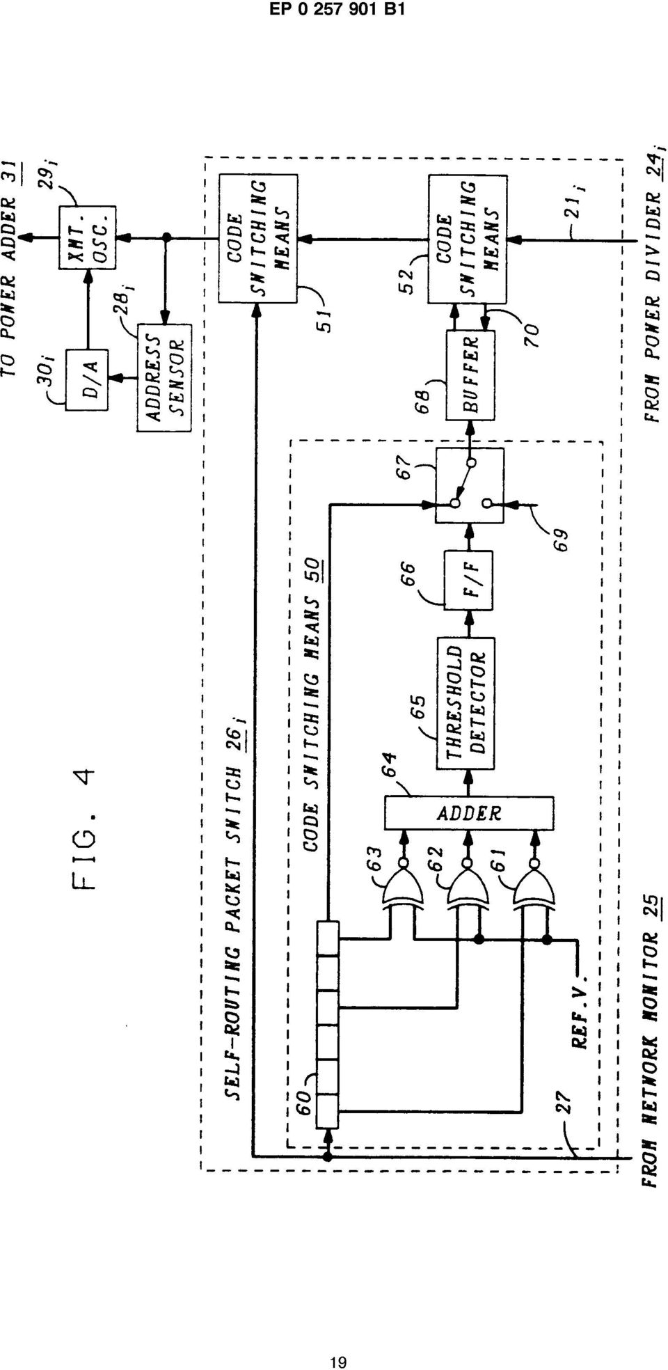
4 EP B1 is added, via a coupler or power adder 15, to the FDM signals from other users of the system which are propagating along transmission medium 11 towards channel switching means 10. The FDM signals propagating along transmission medium 11 are received in channel switching means 10 by a power splitter 20 which divides the power of the received FDM signals equally among each of L paths 21 1 to 2U, where L ^ N. The following description relates to the functioning of a system configuration under the condition where L = N. Under such condition, there are an equal number of (1) paths 21 in channel switching means 10 and (2) transceivers 12, and each of the transmitting oscillators 14 in transceivers 12i to 12N transmits its FDM signal using a separate fixed assigned frequency channel. This fixed separate FDM transmitting channel used by transmitting portion of a transceiver 12 can correspond to the fixed assigned separate frequency channel used for receiving signals in that same transceiver from channel switching means 10 via transmission medium 13 and destined for the associated user. Where L = N, each of the N paths 21 in channel switching means 10 includes a filter 22,- which is tuned to pass only the frequency band of the fixed assigned transmitting channel of a separate one of transceivers 12i to 12N. In other words, since there are N paths 21 in channel switching means 10, each of the paths 21 1 to 21 N is assigned, or tuned, to receive and process only the transmissions from transceivers 12i to 12N, respectively, and to route such transmissions to transmission medium 13, using the appropriate fixed assigned FDM receive channel of the destined user, or to the external network depending on the destination address of each packet. Whenever filters are used for reception, it is understood that this includes the use of wavelength selective couplers, heterodyne receiver with assigned local oscillator frequency, etc. The output from a filter 22,- in a path 21, is demodulated to an electrical baseband signal in an associated separate demodulator 23,-, which baseband signal is delivered to an associated separate signal power divider 24,-. The power divider 24,- in each path functions to split the power of the input signal equally between the output paths to (1) a network monitor 25 and (2) one input of a separate associated self-routing switch 26,-. Network Monitor 25 includes a microprocessor and memory (not shown) which functions to receive the packets at the outputs of power dividers 24i to 24L and detect which of paths 21 include active transmissions and where their transmissions are destined. From such active user and path detections, network controller 25 maintains an updated list of all active and non-active transceivers 12 and, when required, a list of all available transmit FDM channels. The available list of active/inactive users can be provided to all of the system users, if desired, by, for example, inserting such information 5 as part of a transmitted preamble to each receiver to avoid the initiation of a call that conflicts with an already active user. This list of active/inactive users can be introduced into, for example, the monitor preamble section 40 of every packet by the assoio ciated self-routing switch 26,- via the connection 27 from network monitor 25 before transmission to the appropriate user over transmission medium 13. A more preferable method, however, would be for network monitor 25 to recognize the first packet is received from a prior inactive user on transmission medium 11, and compare the destination address received in the packet with the active/inactive user list in memory. If the destined user is inactive, network monitor 25 permits the packet to proceed 20 through the associated path 21 to transmission medium 13. If the destined user is presently active, network monitor 25 causes a busy signal, and the originating user's destination code, to be introduced into the appropriate portions of the packet 25 via lead 27 for subsequent transmission back to the originating user in that user's assigned FDM receive channel via transmission medium 13 and that user's receiver. Network monitor 25 in receiving the packets 30 from all paths 21, can also compare the destination address included in the received preamble with that of the address associated with the external network and, if it matches, to route such packet to the external network. Similarly, if a packet arrives 35 from the external network for one of the system users, network monitor 25 checks the included destination address in the preamble of the received packet and then inserts the appropriate destined user's address code in monitor preamble informa- 40 tion section 41 and a unique monitor whole packet start code in the preamble portion 41, as shown in FIG. 3, corresponding to the unique start code of the appropriate one of the L self-routing switches 26i to 26L. Monitor 25 then routes the packet via 45 lead 27 to the self-routing switches 26. As shown in FIG. 4, each self-routing switch 26, receives signals on lead 27 from network monitor 25 in separate code switching means 50 and 51. As shown in code switching means 50, the input 50 signal from network monitor 25 is received in a shift register 60. As the bits of the received information are shifted through register 60, certain of the momentarily stored bits, as, for example, bits 1, 4 and 6 of a six bit register 60 are delivered to 55 negative Exclusive-Or (EX-OR) gates 61-63, respectively. The length of shift register 60 and the choice of the bits therein to be delivered to separate negative EX-OR gates in code switching
 paths 21 in channel switching means 10 and (2) transceivers 12, and each of the transmitting oscillators 14 in transceivers 12i to 12N transmits")
5 EP B1 means 50 are determined by the length and the unique monitor preamble information start code, respectively, which is included in section 42 of the preamble of a packet that identifies the particular self-routing switch 26,- for which the monitor preamble information in preamble section 40 it is meant. This same monitor preamble information start code is included by network monitor 25 in preamble section 43 for the monitor preamble information stop code. Preamble sections 42 and 43 will be found immediately before and after the monitor preamble information section 40 and cause the monitor preamble information in section 40 to be inserted into a packet propagating on path 21. Each of negative EX-OR gates functions to compare the input bit from register 60 with a predetermined reference voltage. Such reference voltage can correspond to that of a logic "1 " or "0" that may be received from register 60. If both inputs to a negative EX-OR gate are the same, a logic 1 voltage level will be produced at its output, while if the two inputs do not match a logic zero voltage level will be produced at the output. The output signals from EX-OR gates are added together in adder 64 and the resultant output signal is delivered to threshold detector 65. Threshold detector 65 checks the level of the input signal from adder 64 and produces an enable signal to the input of a flip-flop (F/F) 66 if the input level is equal to or above a predetermined threshold. F/F 66 can comprise the well-known Flip-flop "T", which is defined in the book "Reference Data For Radio Engineers, 5th Edition, 1968, published by Howard W. Sams & Co., Inc., and has only one input, where a pulse appearing on the input will cause the F/F to change states. Therefore, on a first enable pulse, F/F 66 will produce an output with a first logic value, e.g., a logic 1, and on a next enable pulse F/F 66 will produce an output with a second logic value, e.g., a logic 0, and then return again to the first logic value on the next pulse, etc. A switch, or gating means, 67 functions to connect the output from shift register 60 to the input of a buffer 68 when the enable signal from F/F 66 is at the first logic value, and to connect the unused input 69 of switch 67 to the input of buffer 68 when the signal from F/F 66 is at the second logic value. Buffer 68, therefore, stores the signals from shift register 60 during the time it is connected thereto by switch 67. In operation, code switching means receives the signals from network monitor 25 over lead 27 and has the shift register 60/negative EX-OR gates combination set up to provide a signal level from the adder which is equal to or above the threshold level used for comparison purposes in threshold detector 65 whenever the bits momentarily stored in shift register 60 match the reference voltage of all of the negative EX-OR gates Preferably, this is set up to occur when the monitor preamble information start and stop codes in preamble sections 42 and 43, respectively, are 5 matched with the unique code for the code switching means 50 in a desired separate one of selfrouting switches 26i to 26L. If the preamble sections 42 and 43 do not match the unique start/stop code for switching means 50, then buffer 68 will io not receive any packet information and the empty for that packet period. The code switching means 51 and 52 comprise a similar arrangement to that shown for code is switching means 50, except that their shift register/negative EX-OR gates combination may be arranged to recognize the same or a different start/stop code. More particularly, code switching means 52 receives the packet signals from power divider 24,- in the path 21,- and during the each 20 packet period. If the monitor preamble information start and stop codes, in sections 42 and 43 of the packet on path 21,-, correspond to the proper start/stop codes of code switching means 52, then code switching means 52 will generate an enable 25 signal from its F/F 66 both to its switch 67 and to buffer 68 on lead 70. Such enable signal causes buffer 68 to be connected to path 21,- during the period when the monitor preamble information from power divider 24,- reaches code switching means in order to introduce the monitor preamble information currently stored in buffer 68 into preamble section 40 in place of the preamble information that may have been included in the packet from power divider 24,-. 35 Code switching means 51, on the other hand, functions to check the monitor whole packet start and stop codes in preamble section 41 and postamble section 44, respectively. If the start and stop codes match the unique start and stop codes as- 40 signed to each self-routing switches 26i to 26L, then code switching means 51 permits the entire packet information between the whole packet start and the stop code to be routed onto path 21,- in place of the packet information arriving from code 45 switching means 52. This condition generally occurs when a user is communicating with the external network and the packet received over transmission medium 1 1 is routed by network monitor 25 to the external network and is not to be transmitted to 50 any user over transmission medium 13. For such condition, code switching means 51 blocks such packets from reaching transmission medium 13 and causes the packets from the external network to be routed to transmission medium and the ap- 55 propriate user for achieving two-way communications. When one system user is communicating with a second system user, however, the packet from transmission medium 1 1 passes through code

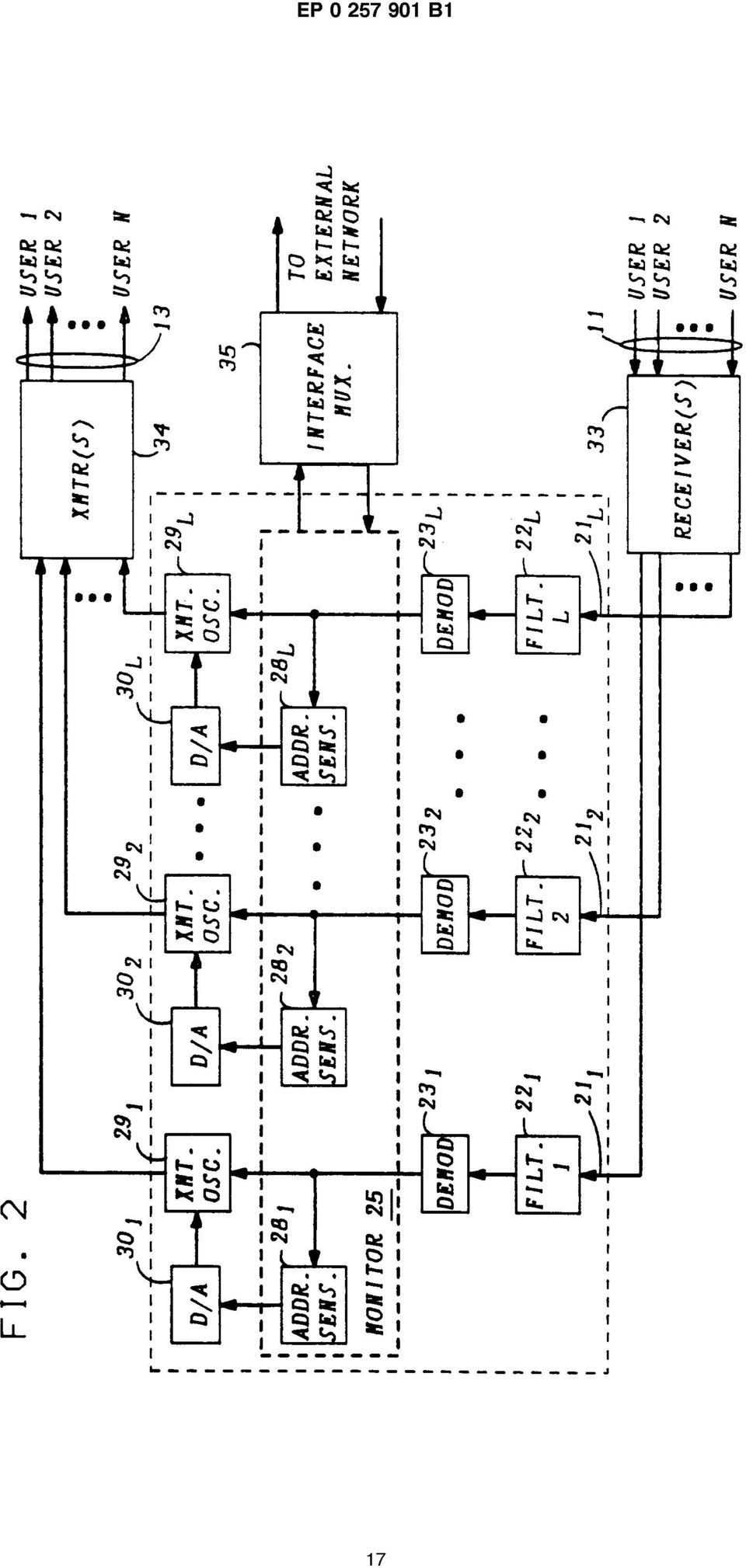
6 EP B1 10 switching means 52, while introducing any monitor preamble information in section 40, and then through code switching means 51 to transmission medium 13. The outputs from self-routing switches 26i to 26L are received by both address sensors 28i to 28L and transmit oscillators 29i to 29L, respectively. Addresses sensors 28i to 28;. function to extract the user's destination address from the preamble of the received packet and to send such address to a digital-to-analog (D/A) converter 30i to 30;., respectively. D/A converters 30i to 30t. convert the received user's destination address into an appropriate control signal for transmission to transmit oscillators 29i to 29L, respectively. The control signal from D/A converter 30 is used to appropriately adjust the carrier of the associated transmit oscillator 29 so that the packet is transmitted at the assigned fixed receive frequency of the destined user's receiver as determined from the destination address in the preamble. All of the FDM packet signals transmitted by transmit oscillators 29i to 29L are combined into one FDM signal by power adder 31 for transmission via transmission medium 13 to all of transceivers 12i to 12N. It is to be understood that the transmit oscillators may be microwave oscillators, oscillating lasers, wavelength tunable lasers, etc. A portion of the combined FDM signal power propagating along transmission medium 13 is coupled out at each transceiver 12 via a power divider, or coupler, 16 with the remaining major portion of the power continuing along transmission medium 13 to the next power divider 16. At each of transceivers 12i to 12N, the signal coupled out by the associated power divider 16 is received by a filter 17 which is tuned to pass only the packets of information received in the fixed assigned receive channel and to block all other channels. The received packets from associated filter 17 are demodulated to an electrical baseband signal by demodulator 18 and transmitted to the associated user. For the case where L<N, it is preferable that the transmit oscillators 14 in transceivers 12i to 12N are each selectively tunable to any one of L FDM transmit channel frequencies via control signals from an associated synthesizer 19, and that the filters 22i to 22L in FDM channel switching means 10 are each tuned to pass only a separate predetermined one of the L FDM channels received from transmission medium 11. Alternatively, the transceivers 12i to 12N can be separated into groups with each group being fixedly assigned, similar to a party line format, to one of the L possible FDM transmit channels. For the condition where the transceivers 12 are selectively tunable to any of the L transmit frequencies, one of the L channels is preferably made a signaling channel for use in call set-up. The N transceiver 12 are, therefore, contending for the remaining lesser number of L-1 paths through channel switching means 10 for 5 normal communications. It should be understood that the ratio of N:L can be determined from estimates of time vs. system usage to provide no blockage or a predetermined minimal amount of blockage through channel switching means 10 dur- io ing times of high traffic. In a preferred method for call set-up, a transceiver 12 transmits to channel switching means 10 a packet in the signaling channel, e.g., channel L, wherein the preamble includes that user's ad- 15 dress and the address of the destined user. At channel switching means 10, network monitor 25 detects such call initiation unless two or more transceivers are simultaneously sending call set-up packets over the signaling channel. If the indicated 20 called party is not busy and one of the L-1 transmit channels is free, monitor 25 marks such free transmit channel as being used and transmits the code of this assigned transmit channel back to the transceiver initiating a call in its fixedly assigned FDM 25 receive channel. Such assigned transmit channel code is set back to the call-initiating transceiver 12, in the monitor preamble information section 40 of the preamble. Where simultaneous call initiation requests are received by network monitor 25, it will 30 not be able to detect the transceiver address or destination address of either request because of interference, and does not send a packet back to either transceiver. When the requesting transceivers do not receive a response within a pre- 35 determined period of time, they will reinitiate the call set-up request until a response is received from network monitor 25. At a transceiver 12,- which is idle and desires to initiate a call, its synthesizer 19 is initialized to 40 provide a control signal to the associated transmit oscillator 14 which causes oscillator 14 to transmit the call set-up information to channel switching means 10 over the signaling channel. When network monitor 25 responds over transmission me- 45 dium 13 with a packet indicating the code of the assigned transmit channel in that transceiver fixed assigned receive channel, synthesizer 19 detects the transmit channel code in the preamble section 40 of the received packet and provides a cor- 50 responding control signal to transmit oscillator 14 to tune oscillator 14 to the assigned one of L transmit channels. FIG. 2 is an arrangement similar to FIG. 1 for providing a head-end FDM channel switching 55 means 10 which can control traffic in a LAN using microwave or optical multiplexed communication with transceivers 12 over transmission mediums 11 and 13. Incoming multiplexed signals from tran-

7 11 EP B1 12 sceivers 12i to 12N on transmission medium 11, which is, for example, air or a coaxial cable for the microwave system or a lightguide for an optical system, are received in a receiver 33. Receiver 33 can comprise L separate receivers, with each receiver being capable of receiving a separate one of the L possible user signals multiplexed on transmission medium 11, or a single receiver capable of receiving all L multiplexed user signals channels on transmission medium 11 and delivering the multiplexed user signals 1-L to paths 21 1 to 21 j_, respectively. Where L = N, there are N separate receivers 33 with each receiver tuned to a separate one of the N possible multiplexed user signals and connected to the appropriate separate one of paths 21 1 to 21 N or one receiver 33 capable of receiving all N multiplexed user channels and delivering the signals for propagation over the associated path 21. Where L<N, there would be only L receivers 33 coupled to L paths 21 or one receiver 33 capable of receiving all L possible multiplexed user signals from medium 11 and delivering those signals onto the associated path 21. Either technique (where L = N or L<N) functions as described previously for the arrangement of FIG. 1. As shown in FIG. 2, a filter 22,- in each path 21, functions to pass only a separate one of the L possible received multiplexed user signals and to block all other signals. The demodulator 23,-, address sensor 28,-, D/A converter 30,- and transmit oscillator 29,- in each path 21, function in the same manner as described for the corresponding components in FIG. 1. More particularly, in each path 21,-, demodulator 23,- demodulates the received signal to baseband and the baseband signal is routed directly to its associated transmit oscillator 29,- and transmitter(s) 34 through network monitor 25. As with receiver(s) 33, transmitter(s) 34 can comprise L separate transmitters with each transmitter associated with a separate one of paths 21 1 to 21 j_, or the signals from the L paths can be combined as shown in FIG. 1 with a power adder 31 and the combined signals transmitted by one transmitter 34. In FIG. 2 the address sensors 28i to 28;. are shown as part of network monitor 25, where each sensor extracts the destination address of the received signal in the associated path 21. This address information is used to tune the associated transmit oscillator 29,- to the frequency of the intended destined user in the manner described for the corresponding components in FIG. 1. Communications to and from locations outside the system can be accomplished through network monitor 25 by directing the received signal to or from a network interface multiplexer 35 which interconnects the present system to an external network. As shown in FIGs. 1 and 2, the present arrangements direct signals in an FDM system by demodulating all signal inputs to a switch 10 to baseband and detecting where the signal is to be 5 sent. Each baseband signal can be hard-wired to its transmitting oscillator which is frequency tuned, by means of the address-portion information of the signal, to the frequency of the transceiver 12 which is the desired destination of the signal. Thus io switching is accomplished without ever connecting or disconnecting wire lines. In addition, various control and other information can be added or changed in all baseband signals in switch 10, e.g., is a list of all busy users or information from an external system. Such hard-wired switching method is very economical because a minimum of equipment is required for each of the many users. For example, each user can be designed to receive only one fixed carrier frequency and to transmit 20 only one fixed carrier frequency, where L = N. The switching method avoids multiple stage interconnections and disconnects and their blocking constraints, noise transients, cross-talk, circuit topology complications, etc. Such system is particularly suit- 25 ed to fiber optic LANs which have wide bandwidth suited for FDM, but it is to be understood that the present invention could be used with other systems such as microwave or infra-red communication systems or combinations of such systems. 30 Although the present invention has been described for a packet switching system, it should be understood that the present invention can also be practiced using other techniques. For example, net- work status and address information can alter- 35 natively be communicated within the network by means of pilot tones which are entirely analog instead of the previously described packet control signals which are digital. For the case of pilot tone control signals, the arrangement of self-routing 40 switch 26,-, of FIG. 4 would have to be modified as shown in FIG. 5. In FIG. 5, if network monitor 25 is to add control information into a signal arriving from power divider 24,-, as performed by elements of 45 FIG. 4, then network monitor 25 transmits the control information, for example, via appropriate pilot tones within the frequency band passed by filter 70 in self-routing switch 26,-. Any pilot tone control signals 71 passing through filter 70 are added to 50 any control pilot tones and the analog information signals already coming from power divider 24,- on lead 21; within adder 72. This combined analog information signal then proceeds through switch 73 to address sensor 28,- which recognizes the ad- 55 dress pilot tone for a particular user and sends the appropriate control information to transmit oscillator 29,- in the manner outlined before. If, however, the information from network monitor 25 is to replace

8 13 EP B1 14 the entire information signal arriving on lead 21, from power divider 24,-, then network monitor 25 transmits a unique pilot tone signal which is passable by a filter 74 in the appropriate self-routing switch 26,- at the start of a transmission. This pilot tone control signal activates switch 73 in the associated self-routing switch 26,- to connect the information signal propagating on lead 27 from network monitor 25 to the output of self-routing switch 26,-. The information signal from network monitor 25 includes the necessary address and other pilot tone control signals and the information destined for the particular user as identified by the included pilot tone address signal. Again address sensor 28, detects the destination address by the included unique pilot tone address and sets transmit oscillator 29,- to the frequency assigned to that user. Alternatively, each user could transmit the address information on a separate FDM signaling channel. In such case, switch 10 need only detect the address channel for converting the associated information signal to that of the destined user. The present switching arrangement could also be practiced in a Star-type LAN configuration as shown in FIG. 6. There, transmission mediums 11 and 13 comprise, for example, separate optical fibers, or leads, from each user. Each user transmits its optical or electrical signal including the address of the destined user. Each exemplary optical fiber or lead of transmission medium 11 is shown as being terminated in the associated power divider 24,- which functions as described before to divide the input signal and provide such signal to path 21; and network monitor 25. The remaining circuitry functions as described hereinbefore for corresponding elements of FIGs. 1 and 2. However, to direct each of the combined FDM information signals back to the destined users over the dedicated optical fibers or leads, where each of the transceivers 12i to 12N expects to receive its signal at a same frequency band over transmission medium 13, the FDM output signal from power adder 31 is directed to each of mixers 8O1 to 80N. At each of mixers 80,-, the FDM output signal from power adder 31 is mixed with a predetermined carrier from associated oscillator 81,-. The carrier frequency supplied by oscillator 81,- corresponds to the carrier for the channel fixedly assigned to the user 12; associated with the separate fiber or lead of transmission medium 13 that is to propagate the output signal from mixer 80,- to that user. The output signal from each of mixers 80 includes the desired information signal within the same frequency band as the desired information signals from all other mixers is then passed through an associated low-pass or narrow bandpass filter 82,- to remove any unwanted out-of-band signals. The output signal from filter 82,- then propagates along its asso- ciated fiber or lead in transmission medium 13 to the associated transceiver 12,- where the signal is detected in a detector 83 and delivered to the associated user. It is to be understood that any 5 combinations of the arrangements of FIGs. 1, 2 or 6 can be implemented for practicing the present invention which provides a switching function without ever connecting or disconnecting wire or optical lines. The signals propagating through switch io 10 can comprise either electrical or optical signals with appropriate circuitry being used for each element to function as described with such signal. Claims An arrangement for Frequency Division Multiplexed (FDM) switching of information signals in a communication system comprising N users (12), each user being assigned to receive 20 information signals destined for that user over a separate one of a plurality of receive channels (13) and to transmit information signals over a separate one of a plurality of transmit channels (11), the switching arrangement (10) 25 comprising: means for receiving (20) a plurality of concurrent multiplexed information signals and transmitting means (29,31) for converting an information signal to an FDM receive signal 30 assigned to a destined user; the switching arrangement (10) characterized by; a plurality of L transmit channels (11) and a plurality of N receive channels (13) wherein 35 L^N, means for receiving (20) up to a plurality of L concurrent multiplexed information signals (11) from a corresponding plurality of up to L active system users (12) and for directing each 40 of the up to L concurrently received information signals to a separate one of L output terminals, each information signal including a destination user's address which is different for each system user; 45 a plurality of L paths (21) for propagating up to L concurrent information signals through the switching arrangement (10), each path being connected to a separate one of the output terminals of the receiving and directing means 50 (20) and including; means (28) responsive to the signal information propagating on each of the plurality of L paths for (a) detecting the destination user's address included in each information 55 signal on each path and (b) generating a separate control signal representative of each detected destination user's address, transmitting means (29,31) responsive to

9 15 EP B1 16 the control signals from the detecting and generating means (28) for converting the information signal propagating on each of the plurality of L paths to the FDM receive channel (13) assigned to the destined user (12) as indicated by the destination user's address detected in the information signal on that path for subsequent transmission of the signal to the destined user. 2. An FDM switching arrangement according to claim 1 CHARACTERISED IN THAT the switching arrangement (10) further comprises: a network monitor (25) including means for receiving the information signals from each of the plurality of L paths (21), and for generating a separate information signal for a selected path, concurrent with the received information signal, which includes information to be inserted into certain portions of the information signal propagating in the selected path which information to be inserted is preceded and succeeded by a predetermined control code which is unique for the selected path; and each path further includes inserting means (26) disposed before the transmitting means (29,31), the inserting means being responsive to the reception of the unique control code identifying the selected path, which precedes and succeeds the information to be inserted into an information signal propagating in the selected path, for inserting the information into that signal. 3. An FDM switching arrangement according to claim 2 CHARACTERIZED IN THAT the inserting means (26) comprises: a plurality of L self-routing switches (SRS), where each SRS is disposed in a separate one of the plurality of L paths (21) and comprises a first input connected to receive the information signal on the associated path, a second input (27) connected to receive the information signals generated by the network monitor (25), and an output connected to both the transmitting means (29,31) and the detecting and generating means (28), each SRS functioning to pass each information signal received at the first input and to overwrite any portion of the received information signal from the first input with the information disposed between the preceding and succeeding control code received at the second input when the control code corresponds to the unique code for the associated path. 4. An FDM switching arrangement according to claim 3 CHARACTERIZED IN THAT each self-routing switch (SRS) comprises: 5 a first code switching means (50) for detecting a first unique preceding and succeeding control code associated with each of the plurality of L paths disposed in a preamble section of each information signal received io from the network monitor (25) at the second input (27), and for inserting control information received at the second input, between the first unique preceding and succeeding control is code, in place of the corresponding preamble information section received at the first input when the first control code corresponds to the unique first control code for the associated path; and a second code switching means (52) for 20 detecting a second unique preceding and succeeding control code associated with each of the plurality of L paths (21), which code is disposed adjacent the front and rear, respectively, of an overall information signal, for in- 25 serting the information signal from the network monitor (25) in place of the packet of information signal received on the associated path when the second control code corresponds to the unique second control code for the asso- 30 ciated path. 5. An FDM switching arrangement according to claim 4 CHARACTERIZED IN THAT 35 the network monitor (25) is further capable of (a) detecting if the destination user's address in each received information signal is the address of an external network connection, and routing such information signal to the external 40 network, and (b) routing information signals received from the external network onto the proper one of the plurality of L paths (21) by adding the second unique control code adjacent the front and rear of the information signal 45 before transmission to the inserting means (26). 6. An FDM switching arrangement according to claim 3 50 CHARACTERIZED IN THAT the information signal is an analog signal including control codes which are FDM tones, each self-routing switch (SRS) comprising: signal introduction means including filter- 55 ing means for passing only a unique control signal tone assigned to the associated one of the plurality of L paths; and code switching means responsive to the
, and for generating a separate information signal for a selected path, concurrent with the received information signal, which includes information")
10 17 EP B1 18 unique control signal tone from the filtering means for inserting an information signal received from the network monitor in place of the information signal received from the associated path. 7. An FDM switching arrangement according to claim 6 CHARACTERIZED IN THAT the self-routing switch (SRS) further comprises: second signal introduction means including filtering means for passing only selected FDM control signal tones received from the network monitor, and an adder for adding the FDM control tones passed by the filtering means to an information signal received on the associated path. 8. An arrangement for Frequency Division Multiplexed (FDM) switching of information signals in a switched communication system comprising N users (21) wherein each user receives signals from the switching arrangement (10) destined for that user over a separate link (13) and transmits information signals over a separate link (11) to the switching arrangement, CHARACTERIZED IN THAT the switching arrangement (10) comprises: a plurality of N paths (21), each path being arranged for receiving information signals from a separate one of the N links (11) from the N users (12), each received information signal including a destination user's address which address is different for each system user; means (28) responsive to the information signals on the plurality of N paths (21) for (a) detecting the destination user's address included in each information signal on each of the paths, and (b) generating control signals representative of each detected destination user's address including in an information signal; and transmitting means (29) responsive to the control signals from the detecting and generating means (28) for converting each of the information signals received in the plurality of N paths (21) to the FDM channel assigned to the user as indicated by the detected destination user's address in each of the information signals; and means (31) for directing each of the converted information signals from the transmitting means onto the appropriate link (13) associated with the destined user (12) for transmission to that user. 9. An FDM switching arrangement according to claim 8 CHARACTERIZED IN THAT the switching arrangement (10) further 5 comprises: a network monitor (25) including means for receiving the information signals from each of the plurality of N paths (21), and for generating a separate information signal for a selected io path, concurrent with the received information signal, which includes information to be inserted into certain portions of the information signal propagating in the selected path, which is information to be inserted is preceded and succeeded by a predetermined control code which is unique for the selected path; and each path further includes inserting means (26) disposed before the transmitting means which is responsive to the 20 reception of the unique control code identifying the selected path which precedes and succeeds the information to be inserted into an information signal propagating in the selected path for inserting the information into that sig- 25 nal. Patentanspruche 1. Anordnung zur Frequenzmultiplex-(FDM)-Ver- 30 mittlung von Informationssignalen in einem Kommunikationssystem mit N Benutzern (12), wobei jeder Benutzer fur den Empfang von fur diesen Benutzer bestimmten Informationssignalen uber einen getrennten Empfangskanal 35 einer Vielzahl von Empfangskanalen (13) und zur Aussendung von Informationssignalen uber einen getrennten Sendekanal einer Vielzahl von Sendekanalen (11) vorgesehen ist, mit einer Einrichtung (20) zum Empfangen einer 40 Vielzahl von gleichzeitigen, multiplexierten Informationssignalen und einer Sendeeinrichtung (29,31) zur Umwandlung eines Informationssignals in ein FDM-Empfangssignal, das einem Bestimmungsbenutzer zugeordnet ist, 45 gekennzeichnet durch eine Vielzahl L von Sendekanalen (11) und eine Vielzahl N von Empfangskanalen (13), wobei L<N ist, eine Einrichtung (20) zum Empfang von bis zu 50 einer Vielzahl von L gleichzeitigen, multiplexierten Informationssignalen (11) von einer entsprechenden Vielzahl von bis zu L aktiven Systembenutzern (12) und zur Weiterleitung jedes der L gleichzeitig empfangenen Informa- 55 tionssignale an einen getrennten AusgangsanschluB von L Ausgangsanschlussen, wobei jedes Informationssignal eine Bestimmungsbenutzeradresse enthalt, die fur jeden Systemben- 10

11 19 EP B1 20 utzer unterschiedlich ist, eine Vielzahl L von Wegen (21) zur Ubertragung von bis zu L gleichzeitigen Informationssignalen uber die Vermittlungsanordnung (10), wobei jeder Weg mit einem getrennten Aus- 5 gangsanschlub jeder Empfangs- und Weiterleitungsanordnung (20) verbunden ist, und aufweist: eine Einrichtung (28), die unter Ansprechen auf die auf jedem der Vielzahl von L Wegen uber- 10 tragenen Signalinformation (a) die Bestimmungsbenutzeradresse in jedem Informationssignal auf jedem Weg feststellt und (b) ein getrenntes Steuersignal erzeugt, das jede festgestellte Bestimmungsbenutzeradresse dar- is stellt, eine Sendeeinrichtung (29,31), die unter Ansprechen auf die Steuersignale von der Feststell- und Erzeugungseinrichtung (28) das auf jedem der Vielzahl von L Wegen ubertra- 20 gene Informationssignal auf den FDM-Empfangskanal (13) umwandelt, der dem durch die Bestimmungsbenutzeradresse angegebenen Bestimmungsbenutzer (12) zugeordnet ist, wobei die Bestimmungsbenutzeradresse in dem 25 Informationssignal auf dem Weg zur nachfolgenden Ubertragung des Signals an den Bestimmungsbenutzer festgestellt wird. 2. FDM-Vermittlungsanordnung nach Anspruch 1, 30 dadurch gekennzeichnet, dal3 die Vermittlungsanordnung (10) ferner aufweist: einen Netzwerkmonitor (25) zum Empfang der Informationssignale von jedem der Vielzahl von L Wegen (21) und zur Erzeugung gleichzeitig 35 mit dem empfangenen Informationssignal eines getrennten Informationssignals, das Informationen zur Einfugung in bestimmte Teile des uber den gewahlten Weg ubertragenen Informationssignals enthalt, wobei den einzufugenden 40 Informationen ein vorbestimmter Steuercode vorangeht und nachfolgt, der fur den gewahlten Weg besonders zugeordnet ist, und dal3 jeder Weg ferner enthalt: eine vor der Sendeeinrichtung (29,31) einge- 45 setzte Einfugungseinrichtung (26), die auf den Empfang des besonders zugeordneten, den gewahlten Weg identifizierenden und der in ein uber den gewahlten Weg ubertragenes Informationssignal einzufugenden Information vor- so angehenden und nachfolgenden Steuercode die Information in das Signal einfugt. getrennten Weg der Vielzahl von L Wegen (21) liegt und einen ersten Eingang zum Empfang des Informationssignals auf dem zugeordneten Weg, einen zweiten Eingang (27) zum Empfang der durch den Netzwerkmonitor (25) erzeugten Informationssignale und einen Ausgang besitzt, der sowohl mit der Sendeeinrichtung (29,31) als auch mit der Feststell- und Erzeugungseinrichtung (28) verbunden ist, wobei jeder SRS jedes am ersten Eingang empfangene Informationssignal durchlabt und jeden Teil des empfangenen Informationssignals vom ersten Eingang mit der am zweiten Eingang empfangenen Information zwischen dem vorangehenden und nachfolgenden Steuercode uberschreibt, wenn der Steuercode dem besonders zugeordneten Code fur den zugeordneten weg entspricht. 4. FDM-Vermittlungsanordnung nach Anspruch 3, dadurch gekennzeichnet, dal3 jeder selbst-wegfuhrende Schalter (SRS) aufweist: eine erste Codeschalteinrichtung (50) zur Feststellung eines ersten, besonders zugeordneten, vorangehenden und nachfolgenden Steuercode, der jeden der Vielzahl von L Wegen zugeordnet ist und in einem Praambel-Abschnitt jedes vom Netzwerkmonitor (25) am zweiten Eingang (27) empfangenen Informationssignals angeordnet ist, und zur Einfugung von am zweiten Eingang empfangenen Steuerinformationen zwischen den ersten, besonders zugeordneten, vorangehenden und nachfolgenden Steuercode anstelle des entsprechenden Praambel-lnformationsabschnitts, der am ersten Eingang empfangen wird, wenn der erste Steuercode dem besonders zugeordneten ersten Steuercode fur den zugeordneten Weg entspricht, und eine zweite Codeschalteinrichtung (52) zur Feststellung eines zweiten, besonders zugeordneten, vorangehenden und nachfolgenden Steuercode, der jedem der Vielzahl von L Wegen (21) zugeordnet ist und nahe dem Anfang bzw. dem Ende eines Gesamtinformationssignals angeordnet ist, urn das informationssignal vom Netzwerkmonitor (25) anstelle des Paketes von Informationssignalen einzufugen, das auf dem zugeordneten Weg empfangen wird, wenn der zweite Steuercode dem besonders zugeordneten zweiten Steuercode fur den zugeordneten Weg entspricht. 3. FDM-Vermittlungsanordnung nach Anspruch 2, dadurch gekennzeichnet, dal3 die Einfugungseinrichtung (26) umfabt: eine Vielzahl L von selbst-wegfuhrenden Schaltern (SRS), wobei jeder SRS in einem FDM-Vermittlungsanordnung nach Anspruch 4, dadurch gekennzeichnet, dal3 der Netzwerkmonitor (25) ferner in der Lage ist, (a) festzustellen, ob die Bestimmungsbenutzeradresse in jedem empfangenen Informationssignal die 11
, die unter Ansprechen auf die Steuersignale von der Feststell- und Erzeugungseinrichtung (28) das auf jedem der Vielzahl von L")
12 21 EP B1 22 Adresse einer externen Netzwerkverbindung ist und dieses Informationssignal zum externen Netzwerk fuhrt, und (b) vom externen Netzwerk emfpangene Informationssignale auf den richtigen Weg der Vielzahl von L von Wegen (21) zu fuhren, indem der besonders zugeordnete zweite Steuercode nahe dem Anfang und dem Ende des Informationssignals vor einer Aussendung zu der Einfugungseinrichtung (26) hinzugefugt wird. 6. FDM-Vermittlungsanordnung nach Anspruch 3, dadurch gekennzeichnet, dal3 das Informationssignal ein Analogsignal mit FDM-T6nen als Steuercodierungen ist und jeder selbst-wegfuhrende Schalter (SRS) aufweist: eine Signaleinfuhrungseinrichtung einschlieblich einer Filtereinrichtung, die nur einen besonders zugeordneten Steuersignalton durch- Ial3t, der dem zugeordneten Weg der Vielzahl von L Wegen zugeordnet ist, und eine Codeschalteinrichtung, die unter Ansprechen auf den besonders zugeordneten Steuersignalton von der Filtereinrichtung ein vom Netzwerkmonitor empfangenes Informationssignal anstelle des von dem zugeordneten Weg empfangenen Informationssignals einfugt. 7. FDM-Vermittlungsanordnung nach Anspruch 6, dadurch gekennzeichnet, dal3 der selbst-wegfuhrende Schalter (SRS) ferner aufweist: eine zweite Signaleinfuhrungseinrichtung einschlieblich einer Filtereinrichtung, die nur gewahlte, vom Netzwerkmonitor empfangene FDM-Steuersignaltone durchlabt, und einen Addierer, der von der Filtereinrichtung durchgelassene FDM-Steuertone einem von dem zugeordneten Weg empfangenen Informationssignal hinzufugt. 8. Anordnung zur Frequenzmultiplex-(FDM)-Vermittlung von Informationen in einem Kommunikationsvermittlungssystem mit N Benutzern (21), wobei jeder Benutzer fur diesen Benutzer bestimmte Signale von der Vermittlungsanordnung (7) uber eine getrennte Verbindung (13) empfangt und Informationssignale uber eine getrennte Verbindung (11) zur Vermittlungsanordnung ubertragt, dadurch gekennzeichnet, dal3 die Vermittlungsanordnung (10) aufweist: eine Vielzahl N von Wegen (21), wobei jeder Weg zur Aufnahme von Informationssignalen von einer getrennten Verbindung der N Verbindungen (11) von den N Benutzern (12) empfangt und jedes empfangene Informationssignal eine Bestimmungsbenutzeradresse enthalt, die fur jeden Systembenutzer verschieden ist, eine Einrichtung (28), die unter Ansprechen auf die Informationssignale auf der vielzahl von N Wegen (21) (a) die Bestimmungsbenutzer- 5 adresse in jedem Informationssignal auf jedem der Wege feststellt und (b) Steuersignale erzeugt, die jede festgestellte Bestimmungsbenutzeradresse in einem Informationssignal darstellen, io eine Sendeeinrichtung (29), die untere Ansprechen auf die Steuersignale von der Feststellund Erzeugungseinrichtung (28) jedes auf der Vielzahl von N Wegen (21) empfangene Informationssignal in den FDM-Kanal umwandelt, is der dem durch die festgestellte Bestimmungsbenutzeradresse in jedem Informationssignal angezeigten Benutzer zugeordnet ist, und eine Einrichtung (31) zur Ubertragung jedes der umgewandelten Informationssignale von 20 der Sendeeinrichtung auf die jeweilige, dem Bestimmungsbenutzer (12) zugeordnete Verbindung (13) fur eine Ubertragung zu dem Benutzer FDM-Vermittlungsanordnung nach Anspruch 8, dadurch gekennzeichent, dal3 die Vermittlungsanordnung (10) ferner aufweist: einen Netzwerkmonitor (25) einschlieblich einer Einrichtung zum Empfang der Informationssi- 30 gnale von jedem dere Vielzahl von N Wegen (21) und zur Erzeugung eines getrennten Informationssignals gleichzeitig mit dem empfangenen Informationssignals fur einen gewahlten Weg, das in bestimmte Teile des uber den 35 gewahlten Weg ubertragenen Informationssignals einzufugende Informationen enthalt, denen ein vorbestimmter fur den gewahlten Weg besonders zugeordneter Steuercode vorangeht und nachfolgt, 40 wobei jeder Weg ferner eine Einfugungseinrichtung (26) enthalt, die vor der Sendeeinrichtung eingesetzt ist und unter Ansprechen auf den Empfang des besonders zugeordneten Steuercode, der den gewahlten Weg identifies ziert und der in ein auf dem gewahlten Weg ubertragenes Informationssignal einzufugenden Information vorangeht und nachfolgt, die Information in das Signal einfugt. 50 Revendications 1. Une structure pour la commutation par multiplexage de frequence de signaux d'information dans un systeme de telecommunication com- 55 prenant N utilisateurs (12), chaque utilisateur etant designe pour recevoir des signaux d'information destines a cet utilisateur sur un canal separe parmi un ensemble de canaux de 12
")
13 23 EP B1 24 reception (13), et pour emettre des signaux d'information sur un canal separe parmi un ensemble de canaux d'emission (11), la structure de commutation comprenant : des moyens (20) destines a recevoir un ensemble de signaux d'information multiplexes simultanes, et des moyens d'emission (29, 31) destines a convertir un signal d'information en un signal de reception de multiplex de frequence attribue a un utilisateur de destination; la structure de commutation (10) etant caracterisee par : un ensemble de L canaux d'emission (11) et un ensemble de N canaux de reception (13), avec L ^ N, des moyens (20) destines a recevoir un ensemble comprenant jusqu'a L signaux d'information multiplexes simultanes (11) provenant d'un ensemble correspondant comprenant jusqu'a L utilisateurs de systeme actifs (12), et a diriger chacun des signaux d'information regus simultanement, en un nombre allant jusqu'a L, vers I'une separee de L bornes de sortie, chaque signal d'information comprenant une adresse d'utilisateur de destination qui est differente pour chaque utilisateur du systeme; un ensemble de L voies (21) pour propager jusqu'a L signaux d'information simultanes a travers la structure de commutation (10), chaque voie etant connectee a I'une separee des bornes de sortie des moyens (20) qui regoivent et dirigent des signaux, et comprenant : des moyens (28) reagissant a I'information de signal qui se propage sur chacune des voies de I'ensemble de L voies en accomplissant les operations suivantes : (a) detection de I'adresse d'utilisateur de destination qui est incluse dans chaque signal d'information sur chaque voie, et (b) generation d'un signal de commande separe representatif de chaque adresse d'utilisateur de destination detectee, des moyens d'emission (29, 31) qui reagissent aux signaux de commande provenant des moyens de detection et de generation (28) en convertissant le signal d'information qui se propage sur chaque voie de I'ensemble de L voies vers le canal de reception de multiplex temporel (13) qui est attribue a I'utilisateur de destination (12), comme indique par I'adresse d'utilisateur de destination qui est detectee dans le signal d'information sur cette voie, pour emettre ensuite le signal vers I'utilisateur de destination. 2. Une structure de commutation par multiplexage de frequence selon la revendication 1 CARACTERISEE EN CE QUE la structure de commutation (10) comprend en outre : un controleur de reseau (25) comprenant des moyens qui sont destines a recevoir les signaux d'information provenant de chaque voie parmi I'ensemble de L voies (21), et a generer un signal d'information separe pour une voie selectionnee, en simultaneity avec le signal d'information regu, qui contient une in- 70 formation a inserer dans certaines parties du signal d'information se propageant dans la voie selectionnee, cette information a inserer etant precedee et suivie par un code de commande predetermine qui est specifique de la voie se- 75 lectionnee; et chaque voie comprend en outre des moyens d'insertion (26) disposes avant les moyens d'emission (29, 31), les moyens d'insertion reagissant a la reception 20 du code de commande specifique identifiant la voie selectionnee, qui precede et suit I'information a inserer dans un signal d'information se propageant dans la voie selectionnee, de fagon a inserer I'information dans ce signal Une structure de commutation par multiplexage de frequence selon la revendication 2 CARACTERISEE EN CE QUE les moyens d'insertion (26) comprennent : 30 un ensemble de L commutateurs a autoacheminement, chaque commutateur a autoacheminement etant dispose dans une voie separee parmi I'ensemble L voies (21) et comprenant une premiere entree connectee pour 35 recevoir le signal d'information present sur la voie associee, une seconde entree (27) connectee de fagon a recevoir les signaux d'information qui sont generes par le controleur de reseau (25), et une sortie qui est 40 connectee a la fois aux moyens d'emission (29, 31) et aux moyens de detection et de generation (28), chaque commutateur a autoacheminement transmettant chaque signal d'information regu sur la premiere entree et rem- 45 plagant toute partie du signal d'information regu qui provient de la premiere entree, par I'information qui est disposee entre les codes de commande precedent et suivant qui sont regus sur la seconde entree, lorsque le code 50 de commande correspond au code specifique pour la voie associee. 4. Une structure de commutation par multiplexage de frequence selon la revendication 3 55 CARACTERISEE EN CE QUE chaque commutateur a auto-acheminement comprend: une premiere structure de commutation de 13
, avec L ^ N, des moyens (20) destines a recevoir un ensemble comprenant jusqu'a L signaux d'information multiplexes simultanes (11) provenant d'un ensemble correspondant comprenant")
14 25 EP B1 26 code (50) destinee a determiner un premier code de commande precedent et suivant specifique, associe a chaque voie de I'ensemble de L voies, se trouvant dans une section de preambule de chaque signal d'information qui est regu sur la seconde entree (27), a partir du controleur de reseau (25), et destinee a inserer I'information de code regue sur la seconde entree entre les codes de commande precedent et suivant specifiques, a la place de la section d'information de preambule correspondante qui est regue sur la premiere entree, lorsque le premier code de commande correspond au premier code de commande specifique pour la voie associee; et une seconde structure de commutation de code (52) qui est destinee a detecter un second code precedent et suivant specifique associe a chaque voie de I'ensemble de L voies (21), ce code etant place en position adjacente a I'avant et a I'arriere, respectivement, d'un signal d'information global, et qui est destinee a inserer le signal d'information provenant du controleur de reseau (25) a la place du paquet de signal d'information qui est regu sur la voie associee, lorsque le second code de commande correspond au second code de commande specifique pour la voie associee. 5. Une structure de commutation par multiplexage de frequence selon la revendication 4 CARACTERISEE EN CE QUE le controleur de reseau (25) est en outre capable (a) de detecter si I'adresse d'utilisateur de destination dans chaque signal d'information regu est I'adresse d'une connexion de reseau externe, et d'acheminer ce signal d'information vers le reseau externe, et (b) d'acheminer des signaux d'information regus a partir du reseau externe, sur la voie appropriee parmi I'ensemble de L voies (21), en ajoutant le second code specifique en position adjacente a I'avant et a I'arriere du signal d'information, avant remission vers les moyens d'insertion (26). 6. Une structure de commutation par multiplexage de frequence selon la revendication 3 CARACTERISEE EN CE QUE le signal d'information est un signal analogique comprenant des codes de commande qui sont des frequences de multiplex de frequence, chaque commutateur a auto-acheminement comprenant : des moyens d'introduction de signal, comprenant des moyens de filtrage destines a transmettre seulement une frequence de signal de commande specifique qui est attribute a la voie associee parmi I'ensemble de L voies; et une structure de commutation de code qui reagit a la frequence de signal de commande specifique provenant des moyens de filtrage 5 en inserant un signal d'information regu a partir du controleur de reseau, a la place du signal d'information qui est regu a partir de la voie associee. io 7. Une structure de commutation par multiplexage de frequence selon la revendication 6 CARACTERISEE EN CE QUE le commutateur a auto-acheminement comprend en outre : is des seconds moyens d'introduction de signal comprenant des moyens de filtrage qui sont destines a transmettre seulement des frequences de signal de commande de multiplex de frequence 20 selectionnees qui sont regues a partir du controleur de reseau, et un additionneur qui est destine a ajouter les frequences de commande de multiplex de frequence qui sont transmises par les moyens 25 de filtrage, a un signal d'information qui est regu sur la voie associee. 8. Une structure pour la commutation par multiplexage de frequence de signaux d'information 30 dans un systeme de telecommunication commute, comprenant N utilisateurs (21), dans laquelle chaque utilisateur regoit sur une liaison separee (13) des signaux qui proviennent de la structure de commutation (10) et qui sont des- 35 tines a cet utilisateur, et emet des signaux d'information sur une liaison separee (11) vers la structure de commutation, CARACTERISEE EN CE QUE la structure de commutation (10) com- 40 prend : un ensemble de N voies (21), chaque voie etant congue pour recevoir des signaux d'information provenant d'une liaison separee parmi les N liaisons (11) provenant des N utilisateurs 45 (12), chaque signal d'information regu comprenant une adresse d'utilisateur de destination qui est differente pour chaque utilisateur du systeme; des moyens (28) qui reagissent aux si- 50 gnaux d'information sur I'ensemble de N voies (21) en accomplissant les actions suivantes : (a) detection de I'adresse d'utilisateur de destination qui est incluse dans chaque signal d'information sur chacune des voies, et (b) gene- 55 ration de signaux de commande representatifs de chaque adresse d'utilisateur de destination detectee qui est incluse dans un signal d'information; et 14
 qui est destinee a detecter un second code precedent et suivant")
15 27 EP B1 28 des moyens d'emission (29) qui reagissent aux signaux de commande provenant des moyens de detection et de generation (28), en convertissant chacun des signaux d'information regus dans I'ensemble de N voies (21), pour le 5 faire correspondre au canal de multiplex de frequence attribue a I'utilisateur qui est indique par I'adresse d'utilisateur de destination detectee dans chacun des signaux d'information; et des moyens (31) qui sont destines a diri- 10 ger chacun des signaux d'information convertis provenant des moyens d'emission, vers la liaison (13) appropriee qui est associee a I'utilisateur de destination (12), pour remission vers cet utilisateur. is 9. Une structure de commutation par multiplex de frequence selon la revendication 8 CARACTERISEE EN CE QUE la structure de commutation (10) com- 20 prend en outre : un controleur de reseau (25) comprenant des moyens qui sont destines a recevoir les signaux d'information provenant de chaque voie parmi I'ensemble de N voies (21), et a 25 generer un signal d'information separe pour une voie selectionnee, en simultaneity avec le signal d'information regu, qui contient une information a inserer dans certaines parties du signal d'information se propageant dans la voie 30 selectionnee, cette information a inserer etant precedee et suivie par un code de commande predetermine qui est specifique de la voie selectionnee; et chaque voie comprend en outre 35 des moyens d'insertion (26) disposes avant les moyens d'emission, qui reagissent a la reception du code de commande specifique identifiant la voie selectionnee, qui precede et suit I'information a inserer dans un signal d'in- 40 formation se propageant dans la voie selectionnee, en inserant I'information dans ce signal
, pour remission vers cet utilisateur. is 9.")
16 EP B1 TO i FROM OTHER SYSTEM USERS A a. d i 1 * 0. < tv I 1 <o I I CM I 3 CD RETXORK H0HIT0R 25 CD IN esj cm CM 'TO EXTERNAL^ SETffORK esj 16

17
18 EP B1 FIG. 3 MONITOR HHOLE PACKET START CODE 4± MOM I TOR PREAMBLE INFORMATION START CODE 42 MONITOR PREAMBLE INFORMATION 40 MONITOR PREAMBLE INFORMATION STOP CODE _43 MONITOR MHOLE PACKET STOP CODE 44 TT i i i i _1 L_ PREAMBLE INFORMATION POST AMBLE INFORMATION PACKET 18

19
20 EP B1 FIG. 5 TO POKER ADDER 31 i 30;\D/A KHT. OSC ADDRESS SENSOR SELF-ROUTING SNITCH 26 / 74 FREQ. INFO FREQ. FILTER \ 73 J A. I FREQ. FILTER ADDER FREQ. ^27 FROM NETffORK MONITOR n FROM POffER DIVIDER 2Ai FREQ. 20

(51) Int Cl.: H04L 12/56 (2006.01)
 Int Cl.: H04L 12/56 (2006.01)") (19) (11) EP 1 779 90 B1 (12) EUROPEAN PATENT SPECIFICATION (4) Date of publication and mention of the grant of the patent: 28.12.11 Bulletin 11/2 (21) Application number: 0783482.2 (22) Date of filing:
(19) (11) EP 1 779 90 B1 (12) EUROPEAN PATENT SPECIFICATION (4) Date of publication and mention of the grant of the patent: 28.12.11 Bulletin 11/2 (21) Application number: 0783482.2 (22) Date of filing:
(51) Int Cl.: G10L 15/26 (2006.01)
 Int Cl.: G10L 15/26 (2006.01)") (19) TEPZZ Z 8B_T (11) EP 2 023 338 B1 (12) EUROPEAN PATENT SPECIFICATION (4) Date of publication and mention of the grant of the patent: 28.0.14 Bulletin 14/22 (1) Int Cl.: GL /26 (06.01) (21) Application
(19) TEPZZ Z 8B_T (11) EP 2 023 338 B1 (12) EUROPEAN PATENT SPECIFICATION (4) Date of publication and mention of the grant of the patent: 28.0.14 Bulletin 14/22 (1) Int Cl.: GL /26 (06.01) (21) Application
INTRODUCTION TO COMMUNICATION SYSTEMS AND TRANSMISSION MEDIA
 COMM.ENG INTRODUCTION TO COMMUNICATION SYSTEMS AND TRANSMISSION MEDIA 9/6/2014 LECTURES 1 Objectives To give a background on Communication system components and channels (media) A distinction between analogue
*EP001173363B1* EP 1 173 363 B1 (19) (11) EP 1 173 363 B1 (12) EUROPEAN PATENT SPECIFICATION
 (11) EP 1 173 363 B1 (12) EUROPEAN PATENT SPECIFICATION") (19) Europäisches Patentamt European Patent Office Office européen des brevets *EP001173363B1* (11) EP 1 173 363 B1 (12) EUROPEAN PATENT SPECIFICATION (4) Date of publication and mention of the grant of
(19) Europäisches Patentamt European Patent Office Office européen des brevets *EP001173363B1* (11) EP 1 173 363 B1 (12) EUROPEAN PATENT SPECIFICATION (4) Date of publication and mention of the grant of
(51) Int Cl.: G05F 3/26 (2006.01) G05F 3/24 (2006.01)
 Int Cl.: G05F 3/26 (2006.01) G05F 3/24 (2006.01)") (19) Europäisches Patentamt European Patent Office Office européen des brevets (11) EP 1 280 033 B1 (12) EUROPEAN PATENT SPECIFICATION (4) Date of publication and mention of the grant of the patent: 31.0.2006
(19) Europäisches Patentamt European Patent Office Office européen des brevets (11) EP 1 280 033 B1 (12) EUROPEAN PATENT SPECIFICATION (4) Date of publication and mention of the grant of the patent: 31.0.2006
TEPZZ_768 7_B_T EP 1 768 371 B1 (19) (11) EP 1 768 371 B1 (12) EUROPEAN PATENT SPECIFICATION. (51) Int Cl.: H04M 19/04 (2006.01)
 (11) EP 1 768 371 B1 (12) EUROPEAN PATENT SPECIFICATION. (51) Int Cl.: H04M 19/04 (2006.01)") (19) TEPZZ_768 7_B_T (11) EP 1 768 371 B1 (12) EUROPEAN PATENT SPECIFICATION (4) Date of publication and mention of the grant of the patent: 1.01.2014 Bulletin 2014/03 (1) Int Cl.: H04M 19/04 (2006.01)
(19) TEPZZ_768 7_B_T (11) EP 1 768 371 B1 (12) EUROPEAN PATENT SPECIFICATION (4) Date of publication and mention of the grant of the patent: 1.01.2014 Bulletin 2014/03 (1) Int Cl.: H04M 19/04 (2006.01)
(51) Int Cl.: H04L 29/06 (2006.01) H04M 15/00 (2006.01)
 Int Cl.: H04L 29/06 (2006.01) H04M 15/00 (2006.01)") (19) TEPZZ 7Z 74 B_T (11) EP 2 702 742 B1 (12) EUROPEAN PATENT SPECIFICATION (4) Date of publication and mention of the grant of the patent:.04. Bulletin /16 (21) Application number: 1171674.6 (22) Date
(19) TEPZZ 7Z 74 B_T (11) EP 2 702 742 B1 (12) EUROPEAN PATENT SPECIFICATION (4) Date of publication and mention of the grant of the patent:.04. Bulletin /16 (21) Application number: 1171674.6 (22) Date
(51) Int Cl.: H04L 9/32 (2006.01) G09C 1/00 (2006.01) G06F 21/33 (2013.01) H04L 29/06 (2006.01)
 Int Cl.: H04L 9/32 (2006.01) G09C 1/00 (2006.01) G06F 21/33 (2013.01) H04L 29/06 (2006.01)") (19) TEPZZ Z48B_T (11) EP 2 2 048 B1 (12) EUROPEAN PATENT SPECIFICATION (4) Date of publication and mention of the grant of the patent: 13.0. Bulletin / (21) Application number: 1179238.6 (22) Date of
(19) TEPZZ Z48B_T (11) EP 2 2 048 B1 (12) EUROPEAN PATENT SPECIFICATION (4) Date of publication and mention of the grant of the patent: 13.0. Bulletin / (21) Application number: 1179238.6 (22) Date of
(51) Int Cl.: G06F 11/14 (2006.01) G06F 12/08 (2006.01)
 Int Cl.: G06F 11/14 (2006.01) G06F 12/08 (2006.01)") (19) TEPZZ 488949B_T (11) EP 2 488 949 B1 (12) EUROPEAN PATENT SPECIFICATION (4) Date of publication and mention of the grant of the patent: 07.0.14 Bulletin 14/19 (21) Application number: 76367.4 (22)
(19) TEPZZ 488949B_T (11) EP 2 488 949 B1 (12) EUROPEAN PATENT SPECIFICATION (4) Date of publication and mention of the grant of the patent: 07.0.14 Bulletin 14/19 (21) Application number: 76367.4 (22)
(51) Int Cl.: G06F 3/12 (2006.01)
 Int Cl.: G06F 3/12 (2006.01)") (19) TEPZZ_ 8 B_T (11) EP 1 38 23 B1 (12) EUROPEAN PATENT SPECIFICATION (4) Date of publication and mention of the grant of the patent: 16.04.14 Bulletin 14/16 (1) Int Cl.: G06F 3/12 (06.01) (21) Application
(19) TEPZZ_ 8 B_T (11) EP 1 38 23 B1 (12) EUROPEAN PATENT SPECIFICATION (4) Date of publication and mention of the grant of the patent: 16.04.14 Bulletin 14/16 (1) Int Cl.: G06F 3/12 (06.01) (21) Application
Multiplexing on Wireline Telephone Systems
 Multiplexing on Wireline Telephone Systems Isha Batra, Divya Raheja Information Technology, Dronacharya College of Engineering Farrukh Nagar, Gurgaon, India ABSTRACT- This Paper Outlines a research multiplexing
(51) Int Cl.: H04L 29/06 (2006.01) (56) References cited:
 Int Cl.: H04L 29/06 (2006.01) (56) References cited:") (19) (11) EP 1 4 48 B1 (12) EUROPEAN PATENT SPECIFICATION (4) Date of publication and mention of the grant of the patent: 06.08.08 Bulletin 08/32 (21) Application number: 02776379.6 (22) Date of filing:..02
(19) (11) EP 1 4 48 B1 (12) EUROPEAN PATENT SPECIFICATION (4) Date of publication and mention of the grant of the patent: 06.08.08 Bulletin 08/32 (21) Application number: 02776379.6 (22) Date of filing:..02
(51) Int Cl.: H04L 12/24 (2006.01) G06F 9/445 (2006.01)
 Int Cl.: H04L 12/24 (2006.01) G06F 9/445 (2006.01)") (19) (12) EUROPEAN PATENT SPECIFICATION (11) EP 1 978 672 B1 (4) Date of publication and mention of the grant of the patent: 01.09. Bulletin /3 (1) Int Cl.: H04L 12/24 (06.01) G06F 9/44 (06.01) (21) Application
(19) (12) EUROPEAN PATENT SPECIFICATION (11) EP 1 978 672 B1 (4) Date of publication and mention of the grant of the patent: 01.09. Bulletin /3 (1) Int Cl.: H04L 12/24 (06.01) G06F 9/44 (06.01) (21) Application
(51) Int Cl.: G06F 11/14 (2006.01)
 Int Cl.: G06F 11/14 (2006.01)") (19) (12) EUROPEAN PATENT SPECIFICATION (11) EP 1 08 414 B1 (4) Date of publication and mention of the grant of the patent: 04.03.09 Bulletin 09/ (1) Int Cl.: G06F 11/14 (06.01) (21) Application number:
(19) (12) EUROPEAN PATENT SPECIFICATION (11) EP 1 08 414 B1 (4) Date of publication and mention of the grant of the patent: 04.03.09 Bulletin 09/ (1) Int Cl.: G06F 11/14 (06.01) (21) Application number:
(51) Int Cl.: G01C 21/36 (2006.01)
 Int Cl.: G01C 21/36 (2006.01)") (19) TEPZZ_ 678B_T (11) EP 1 26 78 B1 (12) EUROPEAN PATENT SPECIFICATION (4) Date of publication and mention of the grant of the patent:.09.14 Bulletin 14/37 (1) Int Cl.: G01C 21/36 (06.01) (21) Application
(19) TEPZZ_ 678B_T (11) EP 1 26 78 B1 (12) EUROPEAN PATENT SPECIFICATION (4) Date of publication and mention of the grant of the patent:.09.14 Bulletin 14/37 (1) Int Cl.: G01C 21/36 (06.01) (21) Application
(51) Int Cl.: H04L 12/24 (2006.01) H04L 12/26 (2006.01)
 Int Cl.: H04L 12/24 (2006.01) H04L 12/26 (2006.01)") (19) (11) EP 1 3 219 B1 (12) EUROPEAN PATENT SPECIFICATION (4) Date of publication and mention of the grant of the patent: 03.01.07 Bulletin 07/01 (1) Int Cl.: H04L 12/24 (06.01) H04L 12/26 (06.01) (21)
(19) (11) EP 1 3 219 B1 (12) EUROPEAN PATENT SPECIFICATION (4) Date of publication and mention of the grant of the patent: 03.01.07 Bulletin 07/01 (1) Int Cl.: H04L 12/24 (06.01) H04L 12/26 (06.01) (21)
(51) Int Cl.: G06F 11/14 (2006.01) G06F 17/30 (2006.01)
 Int Cl.: G06F 11/14 (2006.01) G06F 17/30 (2006.01)") (19) TEPZZ_97799B_T (11) EP 1 97 799 B1 (12) EUROPEAN PATENT SPECIFICATION (4) Date of publication and mention of the grant of the patent: 06.0. Bulletin /19 (1) Int Cl.: G06F 11/14 (06.01) G06F 17/ (06.01)
(19) TEPZZ_97799B_T (11) EP 1 97 799 B1 (12) EUROPEAN PATENT SPECIFICATION (4) Date of publication and mention of the grant of the patent: 06.0. Bulletin /19 (1) Int Cl.: G06F 11/14 (06.01) G06F 17/ (06.01)
Analog vs. Digital Transmission
 Analog vs. Digital Transmission Compare at two levels: 1. Data continuous (audio) vs. discrete (text) 2. Signaling continuously varying electromagnetic wave vs. sequence of voltage pulses. Also Transmission
(51) Int Cl.: H04L 12/26 (2006.01)
 Int Cl.: H04L 12/26 (2006.01)") (19) (11) EP 2 169 879 B1 (12) EUROPEAN PATENT SPECIFICATION (4) Date of publication and mention of the grant of the patent: 21.09.11 Bulletin 11/38 (1) Int Cl.: H04L 12/26 (06.01) (21) Application number:
(19) (11) EP 2 169 879 B1 (12) EUROPEAN PATENT SPECIFICATION (4) Date of publication and mention of the grant of the patent: 21.09.11 Bulletin 11/38 (1) Int Cl.: H04L 12/26 (06.01) (21) Application number:
Personal Broadband Networks, PBN (CE74024-3)
") Faculty of Computing, Engineering & Technology Introduction to Radio Systems Personal Broadband Networks, PBN (CE74024-3) Alison L Griffiths C203 A.L.Griffiths@staffs.ac.uk www.soc.staffs.ac.uk/alg1 2004
Faculty of Computing, Engineering & Technology Introduction to Radio Systems Personal Broadband Networks, PBN (CE74024-3) Alison L Griffiths C203 A.L.Griffiths@staffs.ac.uk www.soc.staffs.ac.uk/alg1 2004
RF Network Analyzer Basics
 RF Network Analyzer Basics A tutorial, information and overview about the basics of the RF Network Analyzer. What is a Network Analyzer and how to use them, to include the Scalar Network Analyzer (SNA),
2 Basic Concepts. Contents
 2. Basic Concepts Contents 2 Basic Concepts a. Link configuration b. Topology c. Transmission mode d. Classes of networks 1 a. Link Configuration Data links A direct data link is one that establishes a
Objectives. Lecture 4. How do computers communicate? How do computers communicate? Local asynchronous communication. How do computers communicate?
 Lecture 4 Continuation of transmission basics Chapter 3, pages 75-96 Dave Novak School of Business University of Vermont Objectives Line coding Modulation AM, FM, Phase Shift Multiplexing FDM, TDM, WDM
(51) Int Cl.: H04L 29/06 (2006.01) G06F 9/445 (2006.01) G06F 13/00 (2006.01)
 Int Cl.: H04L 29/06 (2006.01) G06F 9/445 (2006.01) G06F 13/00 (2006.01)") (19) TEPZZ_7486_6B_T (11) EP 1 748 616 B1 (12) EUROPEAN PATENT SPECIFICATION (4) Date of publication and mention of the grant of the patent: 03.09.2014 Bulletin 2014/36 (1) Int Cl.: H04L 29/06 (2006.01)
(19) TEPZZ_7486_6B_T (11) EP 1 748 616 B1 (12) EUROPEAN PATENT SPECIFICATION (4) Date of publication and mention of the grant of the patent: 03.09.2014 Bulletin 2014/36 (1) Int Cl.: H04L 29/06 (2006.01)
(51) Int Cl. 7 : H04B 7/185, H04B 1/40. (56) References cited: WO-A-00/03494
 Int Cl. 7 : H04B 7/185, H04B 1/40. (56) References cited: WO-A-00/03494") (19) Europäisches Patentamt European Patent Office Office européen des brevets *EP001363412B1* (11) EP 1 363 412 B1 (12) EUROPEAN PATENT SPECIFICATION (4) Date of publication and mention of the grant of
(19) Europäisches Patentamt European Patent Office Office européen des brevets *EP001363412B1* (11) EP 1 363 412 B1 (12) EUROPEAN PATENT SPECIFICATION (4) Date of publication and mention of the grant of
'Possibilities and Limitations in Software Defined Radio Design.
 'Possibilities and Limitations in Software Defined Radio Design. or Die Eierlegende Wollmilchsau Peter E. Chadwick Chairman, ETSI ERM_TG30, co-ordinated by ETSI ERM_RM Software Defined Radio or the answer
EECC694 - Shaaban. Transmission Channel
 The Physical Layer: Data Transmission Basics Encode data as energy at the data (information) source and transmit the encoded energy using transmitter hardware: Possible Energy Forms: Electrical, light,
(Refer Slide Time: 2:10)
") Data Communications Prof. A. Pal Department of Computer Science & Engineering Indian Institute of Technology, Kharagpur Lecture-12 Multiplexer Applications-1 Hello and welcome to today s lecture on multiplexer
Data Communications Prof. A. Pal Department of Computer Science & Engineering Indian Institute of Technology, Kharagpur Lecture-12 Multiplexer Applications-1 Hello and welcome to today s lecture on multiplexer
Communication Systems
 AM/FM Receiver Communication Systems We have studied the basic blocks o any communication system Modulator Demodulator Modulation Schemes: Linear Modulation (DSB, AM, SSB, VSB) Angle Modulation (FM, PM)
ELEMENTS OF CABLE TELEVISION
 1 ELEMENTS OF CABLE TELEVISION Introduction Cable television, from its inception, developed in western countries into two separate systems called Master Antenna Television (MATV) and Community Cable Television
Data Transmission. Data Communications Model. CSE 3461 / 5461: Computer Networking & Internet Technologies. Presentation B
 CSE 3461 / 5461: Computer Networking & Internet Technologies Data Transmission Presentation B Kannan Srinivasan 08/30/2012 Data Communications Model Figure 1.2 Studying Assignment: 3.1-3.4, 4.1 Presentation
(51) Int Cl.: G06F 11/14 (2006.01) G06F 17/30 (2006.01)
 Int Cl.: G06F 11/14 (2006.01) G06F 17/30 (2006.01)") (19) TEPZZ 8_B_T (11) EP 2 3 8 B1 (12) EUROPEAN PATENT SPECIFICATION (4) Date of publication and mention of the grant of the patent: 16.04.14 Bulletin 14/16 (1) Int Cl.: G06F 11/14 (06.01) G06F 17/ (06.01)
(19) TEPZZ 8_B_T (11) EP 2 3 8 B1 (12) EUROPEAN PATENT SPECIFICATION (4) Date of publication and mention of the grant of the patent: 16.04.14 Bulletin 14/16 (1) Int Cl.: G06F 11/14 (06.01) G06F 17/ (06.01)
EUROPEAN PATENT APPLICATION. Hudson, NC 28638 (US) Chancery Lane London WC2A 1QU (GB)
 Chancery Lane London WC2A 1QU (GB)") (19) (12) Europaisches Patentamt European Patent Office Office europeen een des brevets EUROPEAN PATENT APPLICATION EP 0 889 344 A1 (43) Date of publication: (51) nt CI.6: G 02 B 6/44 07.01.1999 Bulletin
(19) (12) Europaisches Patentamt European Patent Office Office europeen een des brevets EUROPEAN PATENT APPLICATION EP 0 889 344 A1 (43) Date of publication: (51) nt CI.6: G 02 B 6/44 07.01.1999 Bulletin
(51) Int Cl.: H04L 29/12 (2006.01) H04L 12/56 (2006.01)
 Int Cl.: H04L 29/12 (2006.01) H04L 12/56 (2006.01)") (19) (11) EP 1 993 266 B1 (12) EUROPEAN PATENT SPECIFICATION (4) Date of publication and mention of the grant of the patent: 04.07.12 Bulletin 12/27 (1) Int Cl.: H04L 29/12 (06.01) H04L 12/6 (06.01) (21)
(19) (11) EP 1 993 266 B1 (12) EUROPEAN PATENT SPECIFICATION (4) Date of publication and mention of the grant of the patent: 04.07.12 Bulletin 12/27 (1) Int Cl.: H04L 29/12 (06.01) H04L 12/6 (06.01) (21)
(51) Int Cl.: G06F 13/38 (2006.01) G06F 1/16 (2006.01)
 Int Cl.: G06F 13/38 (2006.01) G06F 1/16 (2006.01)") (19) TEPZZ 9777B_T (11) EP 2 97 77 B1 (12) EUROPEAN PATENT SPECIFICATION (4) Date of publication and mention of the grant of the patent: 1.07.1 Bulletin 1/29 (1) Int Cl.: G06F 13/38 (06.01) G06F 1/16 (06.01)
(19) TEPZZ 9777B_T (11) EP 2 97 77 B1 (12) EUROPEAN PATENT SPECIFICATION (4) Date of publication and mention of the grant of the patent: 1.07.1 Bulletin 1/29 (1) Int Cl.: G06F 13/38 (06.01) G06F 1/16 (06.01)
The front end of the receiver performs the frequency translation, channel selection and amplification of the signal.
 Many receivers must be capable of handling a very wide range of signal powers at the input while still producing the correct output. This must be done in the presence of noise and interference which occasionally
(51) Int Cl.: H04N 7/16 (2011.01)
 Int Cl.: H04N 7/16 (2011.01)") (19) TEPZZ_796 89B_T (11) EP 1 796 389 B1 (12) EUROPEAN PATENT SPECIFICATION (4) Date of publication and mention of the grant of the patent: 04.03.1 Bulletin 1/ (1) Int Cl.: H04N 7/16 (11.01) (21) Application
(19) TEPZZ_796 89B_T (11) EP 1 796 389 B1 (12) EUROPEAN PATENT SPECIFICATION (4) Date of publication and mention of the grant of the patent: 04.03.1 Bulletin 1/ (1) Int Cl.: H04N 7/16 (11.01) (21) Application
Multiplexing. Multiplexing is the set of techniques that allows the simultaneous transmission of multiple signals across a single physical medium.
 Multiplexing Multiplexing is the set of techniques that allows the simultaneous transmission of multiple signals across a single physical medium. The following two factors in data communications lead to
EP 2 455 926 A1 (19) (11) EP 2 455 926 A1 (12) EUROPEAN PATENT APPLICATION. (43) Date of publication: 23.05.2012 Bulletin 2012/21
 (11) EP 2 455 926 A1 (12) EUROPEAN PATENT APPLICATION. (43) Date of publication: 23.05.2012 Bulletin 2012/21") (19) (12) EUROPEAN PATENT APPLICATION (11) EP 2 4 926 A1 (43) Date of publication: 23.0.2012 Bulletin 2012/21 (21) Application number: 11190024.7 (1) Int Cl.: G08B 2/14 (2006.01) G08B 2/00 (2006.01) G0B
(19) (12) EUROPEAN PATENT APPLICATION (11) EP 2 4 926 A1 (43) Date of publication: 23.0.2012 Bulletin 2012/21 (21) Application number: 11190024.7 (1) Int Cl.: G08B 2/14 (2006.01) G08B 2/00 (2006.01) G0B
Module 5. Broadcast Communication Networks. Version 2 CSE IIT, Kharagpur
 Module 5 Broadcast Communication Networks Lesson 1 Network Topology Specific Instructional Objectives At the end of this lesson, the students will be able to: Specify what is meant by network topology
Computers Are Your Future. 2006 Prentice-Hall, Inc.
 Computers Are Your Future 2006 Prentice-Hall, Inc. Computers Are Your Future Chapter 3 Wired and Wireless Communication 2006 Prentice-Hall, Inc Slide 2 What You Will Learn... ü The definition of bandwidth
Introduction to Optical Networks
 Yatindra Nath Singh Assistant Professor Electrical Engineering Department Indian Institute of Technology, Kanpur Email: ynsingh@ieee.org http://home.iitk.ac.in/~ynsingh 1 What are optical network? Telecomm
Traditional Telephony
 Traditional Telephony Basic Components of a Telephony Network This topic introduces the components of traditional telephony networks. Basic Components of a Telephony Network 3 A number of components must
(51) Int Cl.: H04W 4/14 (2009.01)
 Int Cl.: H04W 4/14 (2009.01)") (19) (12) EUROPEAN PATENT SPECIFICATION (11) EP 2 184 897 B1 (4) Date of publication and mention of the grant of the patent: 14.03.12 Bulletin 12/11 (21) Application number: 087774.3 (22) Date of filing:
(19) (12) EUROPEAN PATENT SPECIFICATION (11) EP 2 184 897 B1 (4) Date of publication and mention of the grant of the patent: 14.03.12 Bulletin 12/11 (21) Application number: 087774.3 (22) Date of filing:
Teleprotection Schemes and Equipment. James W. Ebrecht Young Power Equipment Scottsdale, AZ
 * Teleprotection Schemes and Equipment James W. Ebrecht Young Power Equipment Scottsdale, AZ Teleprotection Schemes And Equipment ~ ~ Relay Relay Teleprotection Communications channel Teleprotection Protection
(51) Int Cl.: G06Q 30/00 (2006.01)
 Int Cl.: G06Q 30/00 (2006.01)") (19) (11) EP 1 016 997 B1 (12) EUROPEAN PATENT SPECIFICATION (4) Date of publication and mention of the grant of the patent: 22.07.09 Bulletin 09/ (1) Int Cl.: G06Q /00 (06.01) (21) Application number:
(19) (11) EP 1 016 997 B1 (12) EUROPEAN PATENT SPECIFICATION (4) Date of publication and mention of the grant of the patent: 22.07.09 Bulletin 09/ (1) Int Cl.: G06Q /00 (06.01) (21) Application number:
(51) Int Cl.: G06F 9/455 (2006.01) G06F 9/50 (2006.01)
 Int Cl.: G06F 9/455 (2006.01) G06F 9/50 (2006.01)") (19) TEPZZ 6987 B_T (11) EP 2 698 711 B1 (12) EUROPEAN PATENT SPECIFICATION (4) Date of publication and mention of the grant of the patent: 0.08.1 Bulletin 1/32 (21) Application number: 118777.8 (22) Date
(19) TEPZZ 6987 B_T (11) EP 2 698 711 B1 (12) EUROPEAN PATENT SPECIFICATION (4) Date of publication and mention of the grant of the patent: 0.08.1 Bulletin 1/32 (21) Application number: 118777.8 (22) Date
What Does Communication (or Telecommunication) Mean?
 Mean?") What Does Communication (or Telecommunication) Mean? The term communication (or telecommunication) means the transfer of some form of information from one place (known as the source of information) to
What Does Communication (or Telecommunication) Mean? The term communication (or telecommunication) means the transfer of some form of information from one place (known as the source of information) to
The Advantialer and Its Advantages
 (19) TEPZZ Z B_T (11) EP 2 0 113 B1 (12) EUROPEAN PATENT SPECIFICATION (4) Date of publication and mention of the grant of the patent: 16.09.1 Bulletin 1/38 (21) Application number: 07809477.8 (22) Date
TEPZZ 5 6 ZB_T EP 2 536 230 B1 (19) (11) EP 2 536 230 B1 (12) EUROPEAN PATENT SPECIFICATION. (51) Int Cl.: H04W 68/00 (2009.01)
 (11) EP 2 536 230 B1 (12) EUROPEAN PATENT SPECIFICATION. (51) Int Cl.: H04W 68/00 (2009.01)") (19) TEPZZ 6 ZB_T (11) EP 2 36 2 B1 (12) EUROPEAN PATENT SPECIFICATION (4) Date of publication and mention of the grant of the patent:.04. Bulletin /16 (21) Application number: 11741879.8 (22) Date of
(19) TEPZZ 6 ZB_T (11) EP 2 36 2 B1 (12) EUROPEAN PATENT SPECIFICATION (4) Date of publication and mention of the grant of the patent:.04. Bulletin /16 (21) Application number: 11741879.8 (22) Date of
Guru Ghasidas Vishwavidyalaya, Bilaspur (C.G.) Institute of Technology. Electronics & Communication Engineering. B.
 Institute of Technology. Electronics & Communication Engineering. B.") Guru Ghasidas Vishwavidyalaya, Bilaspur (C.G.) Institute of Technology Electronics & Communication Engineering B.Tech III Semester 1. Electronic Devices Laboratory 2. Digital Logic Circuit Laboratory 3.
Guru Ghasidas Vishwavidyalaya, Bilaspur (C.G.) Institute of Technology Electronics & Communication Engineering B.Tech III Semester 1. Electronic Devices Laboratory 2. Digital Logic Circuit Laboratory 3.
Maximizing Receiver Dynamic Range for Spectrum Monitoring
 Home Maximizing Receiver Dynamic Range for Spectrum Monitoring Brian Avenell, National Instruments Corp., Austin, TX October 15, 2012 As consumers continue to demand more data wirelessly through mobile
(51) Int Cl.: H05K 1/02 (2006.01)
 Int Cl.: H05K 1/02 (2006.01)") (19) (11) EP 1 229 767 B1 (12) EUROPEAN PATENT SPECIFICATION (4) Date of publication and mention of the grant of the patent: 20.01.2010 Bulletin 2010/03 (1) Int Cl.: H0K 1/02 (2006.01) (21) Application
(19) (11) EP 1 229 767 B1 (12) EUROPEAN PATENT SPECIFICATION (4) Date of publication and mention of the grant of the patent: 20.01.2010 Bulletin 2010/03 (1) Int Cl.: H0K 1/02 (2006.01) (21) Application
How To Understand The Concept Of Circuit Switching
 Module 2 Communication Switching Lesson 2 Circuit Switching INSTRUCTIONAL OBJECTIVES GENERAL This lesson is aimed at developing the concept and application of circuit switching which is a very important
(51) Int Cl.: H02H 7/26 (2006.01) H02H 7/30 (2006.01)
 Int Cl.: H02H 7/26 (2006.01) H02H 7/30 (2006.01)") (19) TEPZZ 66ZZ_B_T (11) EP 2 66 001 B1 (12) EUROPEAN PATENT SPECIFICATION (4) Date of publication and mention of the grant of the patent: 11.03. Bulletin /11 (1) Int Cl.: H02H 7/26 (06.01) H02H 7/ (06.01)
(19) TEPZZ 66ZZ_B_T (11) EP 2 66 001 B1 (12) EUROPEAN PATENT SPECIFICATION (4) Date of publication and mention of the grant of the patent: 11.03. Bulletin /11 (1) Int Cl.: H02H 7/26 (06.01) H02H 7/ (06.01)
(56) References cited:
 References cited:") (19) (12) EUROPEAN PATENT SPECIFICATION (11) EP 1 04 B1 (4) Date of publication and mention of the grant of the patent: 26.12.07 Bulletin 07/2 (21) Application number: 03742391.0 (22) Date of filing: 02.07.03
(19) (12) EUROPEAN PATENT SPECIFICATION (11) EP 1 04 B1 (4) Date of publication and mention of the grant of the patent: 26.12.07 Bulletin 07/2 (21) Application number: 03742391.0 (22) Date of filing: 02.07.03
Department of Electrical and Computer Engineering Ben-Gurion University of the Negev. LAB 1 - Introduction to USRP
 Department of Electrical and Computer Engineering Ben-Gurion University of the Negev LAB 1 - Introduction to USRP - 1-1 Introduction In this lab you will use software reconfigurable RF hardware from National
T = 1 f. Phase. Measure of relative position in time within a single period of a signal For a periodic signal f(t), phase is fractional part t p
, phase is fractional part t p") Data Transmission Concepts and terminology Transmission terminology Transmission from transmitter to receiver goes over some transmission medium using electromagnetic waves Guided media. Waves are guided
Data Transmission Concepts and terminology Transmission terminology Transmission from transmitter to receiver goes over some transmission medium using electromagnetic waves Guided media. Waves are guided
How PLL Performances Affect Wireless Systems
 May 2010 Issue: Tutorial Phase Locked Loop Systems Design for Wireless Infrastructure Applications Use of linear models of phase noise analysis in a closed loop to predict the baseline performance of various
(51) Int Cl.: G06F 21/00 (2006.01) H04L 29/06 (2006.01)
 Int Cl.: G06F 21/00 (2006.01) H04L 29/06 (2006.01)") (19) TEPZZ_8Z_7 _B_T (11) EP 1 801 721 B1 (12) EUROPEAN PATENT SPECIFICATION (4) Date of publication and mention of the grant of the patent: 16.06. Bulletin /24 (1) Int Cl.: G06F 21/00 (06.01) H04L 29/06
(19) TEPZZ_8Z_7 _B_T (11) EP 1 801 721 B1 (12) EUROPEAN PATENT SPECIFICATION (4) Date of publication and mention of the grant of the patent: 16.06. Bulletin /24 (1) Int Cl.: G06F 21/00 (06.01) H04L 29/06
(51) Int Cl.: H04L 29/06 (2006.01) H04L 12/26 (2006.01) H04M 3/22 (2006.01) H04M 7/00 (2006.01)
 Int Cl.: H04L 29/06 (2006.01) H04L 12/26 (2006.01) H04M 3/22 (2006.01) H04M 7/00 (2006.01)") (19) TEPZZ 48786B_T (11) EP 2 48 786 B1 (12) EUROPEAN PATENT SPECIFICATION (4) Date of publication and mention of the grant of the patent: 23.03.16 Bulletin 16/12 (21) Application number: 806012.0 (22)
(19) TEPZZ 48786B_T (11) EP 2 48 786 B1 (12) EUROPEAN PATENT SPECIFICATION (4) Date of publication and mention of the grant of the patent: 23.03.16 Bulletin 16/12 (21) Application number: 806012.0 (22)
EUROPEAN PATENT SPECIFICATION. (51) Intel e G06T 11/20
 Intel e G06T 11/20") (19) (12) Europaisches Patentamt European Patent Office Office europeen des brevets EP 0 550 245 B1 EUROPEAN PATENT SPECIFICATION (45) Date of publication and mention of the grant of the patent: 25.03.1998
(19) (12) Europaisches Patentamt European Patent Office Office europeen des brevets EP 0 550 245 B1 EUROPEAN PATENT SPECIFICATION (45) Date of publication and mention of the grant of the patent: 25.03.1998
SECTION 2 TECHNICAL DESCRIPTION OF BPL SYSTEMS
 SECTION 2 TECHNICAL DESCRIPTION OF SYSTEMS 2.1 INTRODUCTION Access equipment consists of injectors (also known as concentrators), repeaters, and extractors. injectors are tied to the backbone via fiber
Fundamentals of Telecommunications
 Fundamentals of Telecommunications Professor of CIS Columbus, OH 43210 Jain@ACM.Org http://www.cis.ohio-state.edu/~jain/ 1 Overview Time Division Multiplexing T1, T3, DS1, E1 T1 Framing Echo Cancellation
Unit of Learning # 2 The Physical Layer. Redes de Datos Sergio Guíñez Molinos sguinez@utalca.cl 1-2009
 Unit of Learning # 2 The Physical Layer Redes de Datos Sergio Guíñez Molinos sguinez@utalca.cl 1-2009 The Theoretical Basis for Data Communication Sergio Guíñez Molinos Redes de Computadores 2 The Theoretical
HP 8970B Option 020. Service Manual Supplement
 HP 8970B Option 020 Service Manual Supplement Service Manual Supplement HP 8970B Option 020 HP Part no. 08970-90115 Edition 1 May 1998 UNIX is a registered trademark of AT&T in the USA and other countries.
MEASUREMENT UNCERTAINTY IN VECTOR NETWORK ANALYZER
 MEASUREMENT UNCERTAINTY IN VECTOR NETWORK ANALYZER W. Li, J. Vandewege Department of Information Technology (INTEC) University of Gent, St.Pietersnieuwstaat 41, B-9000, Gent, Belgium Abstract: Precision
Introduction to Receivers
 Introduction to Receivers Purpose: translate RF signals to baseband Shift frequency Amplify Filter Demodulate Why is this a challenge? Interference (selectivity, images and distortion) Large dynamic range
Performance Management and Fault Management. 1 Dept. of ECE, SRM University
 Performance Management and Fault Management 1 Dept. of ECE, SRM University Performance Management Performance management requires monitoring of the performance parameters for all the connections supported
(51) Int Cl.: B29C 41/20 (2006.01) F21S 4/00 (2006.01) H05K 3/28 (2006.01)
 Int Cl.: B29C 41/20 (2006.01) F21S 4/00 (2006.01) H05K 3/28 (2006.01)") (19) TEPZZ 68698B_T (11) EP 2 68 698 B1 (12) EUROPEAN PATENT SPECIFICATION (4) Date of publication and mention of the grant of the patent: 18.11.201 Bulletin 201/47 (21) Application number: 11808612.3
(19) TEPZZ 68698B_T (11) EP 2 68 698 B1 (12) EUROPEAN PATENT SPECIFICATION (4) Date of publication and mention of the grant of the patent: 18.11.201 Bulletin 201/47 (21) Application number: 11808612.3
TEPZZ 5Z _9_B_T EP 2 502 191 B1 (19) (11) EP 2 502 191 B1 (12) EUROPEAN PATENT SPECIFICATION
 (11) EP 2 502 191 B1 (12) EUROPEAN PATENT SPECIFICATION") (19) TEPZZ Z _9_B_T (11) EP 2 02 191 B1 (12) EUROPEAN PATENT SPECIFICATION (4) Date of publication and mention of the grant of the patent: 17.06.1 Bulletin 1/2 (21) Application number: 787872.0 (22) Date
(19) TEPZZ Z _9_B_T (11) EP 2 02 191 B1 (12) EUROPEAN PATENT SPECIFICATION (4) Date of publication and mention of the grant of the patent: 17.06.1 Bulletin 1/2 (21) Application number: 787872.0 (22) Date
Computer Network. Interconnected collection of autonomous computers that are able to exchange information
 Introduction Computer Network. Interconnected collection of autonomous computers that are able to exchange information No master/slave relationship between the computers in the network Data Communications.
RECOMMENDATION ITU-R M.1453-1 * Transport information and control systems Dedicated short range communications at 5.8 GHz
 Rec. ITU-R M.1453-1 1 RECOMMENDATION ITU-R M.1453-1 * Transport and control systems Dedicated short range communications at 5.8 GHz (Question ITU-R 205/8) (2000-2002) The ITU Radiocommunication Assembly,
Tx/Rx A high-performance FM receiver for audio and digital applicatons
 Tx/Rx A high-performance FM receiver for audio and digital applicatons This receiver design offers high sensitivity and low distortion for today s demanding high-signal environments. By Wayne C. Ryder
EUROPEAN PATENT APPLICATION. (51) intci.e: H04Q 3/00, H04M 3/54
 intci.e: H04Q 3/00, H04M 3/54") (19) (12) Europaisches Patentamt European Patent Office Office europeen des brevets EP 0 696 1 46 A2 EUROPEAN PATENT APPLICATION (43) Date of publication: 07.02.1996 Bulletin 1996/06 (51) intci.e: H04Q
(19) (12) Europaisches Patentamt European Patent Office Office europeen des brevets EP 0 696 1 46 A2 EUROPEAN PATENT APPLICATION (43) Date of publication: 07.02.1996 Bulletin 1996/06 (51) intci.e: H04Q
Telecommunications and the Information Age ET108B. Cell Phone Network
 Telecommunications and the Information Age ET108B Cell Phone Network The Cellular Telephone Network Cellular Telephone Features Carrying Data Across the Cellular Network Satellite Telephone Service Cellular
(51) Int Cl.: G06Q 20/00 (2006.01) G06F 21/00 (2006.01)
 Int Cl.: G06Q 20/00 (2006.01) G06F 21/00 (2006.01)") (19) (12) EUROPEAN PATENT SPECIFICATION (11) EP 1 24 008 B1 (4) Date of publication and mention of the grant of the patent: 29.12. Bulletin /2 (21) Application number: 00992990.2 (22) Date of filing: 31..00
(19) (12) EUROPEAN PATENT SPECIFICATION (11) EP 1 24 008 B1 (4) Date of publication and mention of the grant of the patent: 29.12. Bulletin /2 (21) Application number: 00992990.2 (22) Date of filing: 31..00
TEPZZ 5699Z7B_T EP 2 569 907 B1 (19) (11) EP 2 569 907 B1 (12) EUROPEAN PATENT SPECIFICATION. (51) Int Cl.: H04L 12/803 (2013.01)
 (11) EP 2 569 907 B1 (12) EUROPEAN PATENT SPECIFICATION. (51) Int Cl.: H04L 12/803 (2013.01)") (19) TEPZZ 699Z7B_T (11) EP 2 69 907 B1 (12) EUROPEAN PATENT SPECIFICATION (4) Date of publication and mention of the grant of the patent: 06.0.1 Bulletin 1/19 (21) Application number: 117816.1 (22) Date
(19) TEPZZ 699Z7B_T (11) EP 2 69 907 B1 (12) EUROPEAN PATENT SPECIFICATION (4) Date of publication and mention of the grant of the patent: 06.0.1 Bulletin 1/19 (21) Application number: 117816.1 (22) Date
(51) Int Cl.: H04N 5/225 (2006.01)
 Int Cl.: H04N 5/225 (2006.01)") (19) TEPZZ_94 66_B_T (11) EP 1 942 661 B1 (12) EUROPEAN PATENT SPECIFICATION (4) Date of publication and mention of the grant of the patent: 17.09.2014 Bulletin 2014/38 (1) Int Cl.: H04N /22 (2006.01)
(19) TEPZZ_94 66_B_T (11) EP 1 942 661 B1 (12) EUROPEAN PATENT SPECIFICATION (4) Date of publication and mention of the grant of the patent: 17.09.2014 Bulletin 2014/38 (1) Int Cl.: H04N /22 (2006.01)
Engineering Sciences 151. Electromagnetic Communication Laboratory Assignment 3 Fall Term 1998-99
 Engineering Sciences 151 Electromagnetic Communication Laboratory Assignment 3 Fall Term 1998-99 WAVE PROPAGATION II: HIGH FREQUENCY SLOTTED LINE AND REFLECTOMETER MEASUREMENTS OBJECTIVES: To build greater
GSM/EDGE Output RF Spectrum on the V93000 Joe Kelly and Max Seminario, Verigy
 GSM/EDGE Output RF Spectrum on the V93000 Joe Kelly and Max Seminario, Verigy Introduction A key transmitter measurement for GSM and EDGE is the Output RF Spectrum, or ORFS. The basis of this measurement
Jouve, 18, rue Saint-Denis, 75001 PARIS
 19 Europaisches Patentamt European Patent Office Office europeen des brevets Publication number : 0 651 303 A1 12 EUROPEAN PATENT APPLICATION Application number : 94307908.7 ( ) int. ci.6: G05B 19/042
(51) Int Cl.: H04L 12/46 (2006.01) H04L 29/14 (2006.01) H04L 29/12 (2006.01)
 Int Cl.: H04L 12/46 (2006.01) H04L 29/14 (2006.01) H04L 29/12 (2006.01)") (19) (11) EP 1 342 344 B1 (12) EUROPEAN PATENT SPECIFICATION (4) Date of publication and mention of the grant of the patent: 03.06.09 Bulletin 09/23 (21) Application number: 019639.0 (22) Date of filing:.08.01
(19) (11) EP 1 342 344 B1 (12) EUROPEAN PATENT SPECIFICATION (4) Date of publication and mention of the grant of the patent: 03.06.09 Bulletin 09/23 (21) Application number: 019639.0 (22) Date of filing:.08.01
TEPZZ 96 A_T EP 2 961 111 A1 (19) (11) EP 2 961 111 A1. (12) EUROPEAN PATENT APPLICATION published in accordance with Art.
 (11) EP 2 961 111 A1. (12) EUROPEAN PATENT APPLICATION published in accordance with Art.") (19) TEPZZ 96 A_T (11) EP 2 961 111 A1 (12) EUROPEAN PATENT APPLICATION published in accordance with Art. 13(4) EPC (43) Date of publication:.12.1 Bulletin 1/3 (21) Application number: 147426.7 (22) Date
(19) TEPZZ 96 A_T (11) EP 2 961 111 A1 (12) EUROPEAN PATENT APPLICATION published in accordance with Art. 13(4) EPC (43) Date of publication:.12.1 Bulletin 1/3 (21) Application number: 147426.7 (22) Date
Single channel data transceiver module WIZ2-434
 Single channel data transceiver module WIZ2-434 Available models: WIZ2-434-RS: data input by RS232 (±12V) logic, 9-15V supply WIZ2-434-RSB: same as above, but in a plastic shell. The WIZ2-434-x modules
(12) United States Patent (10) Patent N0.: US 7,068,424 B1 Jennings et al. (45) Date of Patent: Jun. 27, 2006
 United States Patent (10) Patent N0.: US 7,068,424 B1 Jennings et al. (45) Date of Patent: Jun. 27, 2006") US007068424B1 (12) United States Patent (10) Patent N0.: US 7,068,424 B1 Jennings et al. (45) Date of Patent: Jun. 27, 2006 (54) MULTIPLE PULSE GENERATION 6,141,127 A * 10/2000 Boivin et a1...... 398/92
US007068424B1 (12) United States Patent (10) Patent N0.: US 7,068,424 B1 Jennings et al. (45) Date of Patent: Jun. 27, 2006 (54) MULTIPLE PULSE GENERATION 6,141,127 A * 10/2000 Boivin et a1...... 398/92
Four Wave Mixing in Closely Spaced DWDM Optical Channels
 544 VOL. 1, NO. 2, AUGUST 2006 Four Wave Mixing in Closely Spaced DWDM Optical Channels Moncef Tayahi *, Sivakumar Lanka, and Banmali Rawat Advanced Photonics Research lab, Department of Electrical Engineering
CHAPTER 18 THE PUBLIC TELEPHONE NETWORK # DEFINITIONS TERMS
 CHAPTER 18 THE PUBLIC TELEPHONE NETWORK # DEFINITIONS TERMS 1) It uses the largest computer network in the world to interconnect millions of subscribers in such a way that the myriad of companies function
Inventor: Arai,Takao 65-24, Ibukino Midori-ku Yokohama (JP)
") Europaisches Patentamt European Patent Office Office europeen des brevets 00 Publication number: 0137 3 4 6 B1 EUROPEAN PATENT SPECIFICATION Date of publication of patent specification: 25.07.90 Application
Europaisches Patentamt European Patent Office Office europeen des brevets 00 Publication number: 0137 3 4 6 B1 EUROPEAN PATENT SPECIFICATION Date of publication of patent specification: 25.07.90 Application
Construction of High-speed and High-reliability Optical Networks for Social Infrastructure
 Hitachi Review Vol. 59 (Feb. 2010) 1 Construction of High-speed and High-reliability Optical Networks for Social Infrastructure Ryosuke Nishino Hideaki Tsushima, Dr. Eng. Eisuke Sato Shinsuke Tanaka OVERVIEW:
AM TRANSMITTERS & RECEIVERS
 Reading 30 Ron Bertrand VK2DQ http://www.radioelectronicschool.com AM TRANSMITTERS & RECEIVERS Revision: our definition of amplitude modulation. Amplitude modulation is when the modulating audio is combined
Phase II Design for a Multiband LMR Antenna System
 Phase II Design for a Multiband LMR Antenna System S. Ellingson and R. Tillman Aug 30, 2011 Contents 1 Introduction 2 2 System Design 2 3 Antenna Tuner 3 Bradley Dept. of Electrical & Computer Engineering,
Course 1. General view on the fixed telephone network. Digital networks. General aspects. Definitions.
 Course 1. General view on the fixed telephone network. Digital networks. General aspects. Definitions. 1. General view on the fixed telephone network Communication network dedicated to voice transmission;
(51) Int Cl.: G06F 15/02 (2006.01)
 Int Cl.: G06F 15/02 (2006.01)") (19) (11) EP 0 691 619 B1 (12) EUROPEAN PATENT SPECIFICATION (4) Date of publication and mention of the grant of the patent: 07.02.07 Bulletin 07/06 (1) Int Cl.: G06F 1/02 (06.01) (21) Application number:
(19) (11) EP 0 691 619 B1 (12) EUROPEAN PATENT SPECIFICATION (4) Date of publication and mention of the grant of the patent: 07.02.07 Bulletin 07/06 (1) Int Cl.: G06F 1/02 (06.01) (21) Application number:
(51) Int Cl.: H04M 3/50 (2006.01)
 Int Cl.: H04M 3/50 (2006.01)") (19) TEPZZ_Z48_64B_T (11) EP 1 048 164 B1 (12) EUROPEAN PATENT SPECIFICATION (4) Date of publication and mention of the grant of the patent: 07.01.1 Bulletin 1/02 (21) Application number: 9893133.0 (22)
(19) TEPZZ_Z48_64B_T (11) EP 1 048 164 B1 (12) EUROPEAN PATENT SPECIFICATION (4) Date of publication and mention of the grant of the patent: 07.01.1 Bulletin 1/02 (21) Application number: 9893133.0 (22)
Digital Modulation. David Tipper. Department of Information Science and Telecommunications University of Pittsburgh. Typical Communication System
 Digital Modulation David Tipper Associate Professor Department of Information Science and Telecommunications University of Pittsburgh http://www.tele.pitt.edu/tipper.html Typical Communication System Source
(51) Int Cl.: H04L 29/06 (2006.01) H04M 3/56 (2006.01) H04M 3/44 (2006.01) H04L 12/18 (2006.01)
 Int Cl.: H04L 29/06 (2006.01) H04M 3/56 (2006.01) H04M 3/44 (2006.01) H04L 12/18 (2006.01)") (19) TEPZZ Z9 79B_T (11) EP 2 091 179 B1 (12) EUROPEAN PATENT SPECIFICATION (4) Date of publication and mention of the grant of the patent: 17.12.14 Bulletin 14/1 (21) Application number: 07817029.7 (22)
(19) TEPZZ Z9 79B_T (11) EP 2 091 179 B1 (12) EUROPEAN PATENT SPECIFICATION (4) Date of publication and mention of the grant of the patent: 17.12.14 Bulletin 14/1 (21) Application number: 07817029.7 (22)
EUROPEAN PATENT SPECIFICATION. (51) intci.6: G07F 7/10, G06K 19/073. Wilson, Peter J. Leander, TX 78641 (US)
 intci.6: G07F 7/10, G06K 19/073. Wilson, Peter J. Leander, TX 78641 (US)") Europaisches Patentamt (19) (12) European Patent Office Office europeen des brevets EP 0 596 276 B1 EUROPEAN PATENT SPECIFICATION (45) Date of publication and mention of the grant of the patent: 26.05.1999
Europaisches Patentamt (19) (12) European Patent Office Office europeen des brevets EP 0 596 276 B1 EUROPEAN PATENT SPECIFICATION (45) Date of publication and mention of the grant of the patent: 26.05.1999
(51) Int Cl.: H04L 12/00 (2006.01)
 Int Cl.: H04L 12/00 (2006.01)") (19) (11) EP 2 119 B1 (12) EUROPEAN PATENT SPECIFICATION (4) Date of publication and mention of the grant of the patent: 14.12.11 Bulletin 11/0 (21) Application number: 0789037.9 (22) Date of filing: 14.12.07
(19) (11) EP 2 119 B1 (12) EUROPEAN PATENT SPECIFICATION (4) Date of publication and mention of the grant of the patent: 14.12.11 Bulletin 11/0 (21) Application number: 0789037.9 (22) Date of filing: 14.12.07
Overview of WAN Connections Module 1
 Overview of WAN Connections Module 1 Objectives This module introduces the basic elements of WAN connections and describes the role each element plays in creating that connection. After completing this