(51) Int Cl.: H02H 7/26 ( ) H02H 7/30 ( )
|
|
|
- Kenneth Rogers
- 8 years ago
- Views:
Transcription
1 (19) TEPZZ 66ZZ_B_T (11) EP B1 (12) EUROPEAN PATENT SPECIFICATION (4) Date of publication and mention of the grant of the patent: Bulletin /11 (1) Int Cl.: H02H 7/26 (06.01) H02H 7/ (06.01) (21) Application number: (22) Date of filing: (4) Power distribution network fault management Stromverteilungsnetzwerk-Fehlerverwaltung Gestion de pannes de réseau de distribution d énergie (84) Designated Contracting States: AL AT BE BG CH CY CZ DE DK EE ES FI FR GB GR HR HU IE IS IT LI LT LU LV MC MK MT NL NO PL PT RO RS SE SI SK SM TR () Priority: US (43) Date of publication of application: Bulletin 13/ (73) Proprietor: General Electric Company Schenectady, NY 1234 (US) (72) Inventors: Du Toit, Willem Hendrik Cochrane, Alberta T4C 1L1 (CA) Fan, Jiyuan Atlanta, GA Georgia 339 (US) Popescu, Bogdan Cristian Calgary, Alberta T2B 3M1 (CA) (74) Representative: Cleary, Fidelma et al GPO Europe GE International Inc. The Ark 1 Talgarth Road Hammersmith London W6 8BJ (GB) (6) References cited: WO-A2-/ EP B1 Note: Within nine months of the publication of the mention of the grant of the European patent in the European Patent Bulletin, any person may give notice to the European Patent Office of opposition to that patent, in accordance with the Implementing Regulations. Notice of opposition shall not be deemed to have been filed until the opposition fee has been paid. (Art. 99(1) European Patent Convention). Printed by Jouve, 7001 PARIS (FR)
 Priority: 29.08.11 US 11132192 (43) Date of publication of application: 06.03.")
2 1 EP B1 2 Description BACKGROUND OF THE INVENTION [0001] The disclosure relates generally to power distribution management, and more particularly, to fault detection, isolation, and resolution (FDIR), as well as systems, methods, and computer products therefore. [0002] In power distribution networks, faults should be isolated as quickly as possible to protect the rest of the network, such as by disconnecting the affected portion of the network. Once the fault is isolated, power can be restored to at least portions of the network that were taken off line by the fault. Embodiments of the invention disclosed and claimed herein provide system, method, and/or computer product for detecting, isolating, and resolving issues surrounding faults in power distribution networks. [0003] WO-A-/ concerns a system and method for operating an autoloop system in an electrical distribution system. A master controller is in communication with controllers associated with reclosers and switches coupled to branch circuits. The system is arranged to momentarily block the fast tripping function of a feeder recloser in response to the detection of a fault on another branch circuit. The system is also arranged to isolate a segment on which a fault is located and restore electrical power service to areas upstream and downstream from the isolated segment. [0004] The present invention provides a computer-implemented method of power distribution network fault management as defined in appended claim 1, a computer program product as defined in appended claim 12 and a power distribution network fault management system as defmed in appended claim 13. [000] Embodiments of the invention disclosed and claimed herein provide a power distribution network fault management method for a power distribution network including at least one controller configured to execute the method responsive to a fault in the power distribution network, and at least one node configured to communicate with and be responsive to the at least one controller, each controller being configured to store network data, including at least one of device data, topology data, and power demand data. Network data is used to determine a region affected by a first fault, and the region affected is isolated by instructing a nearest upstream node and a nearest downstream node to interrupt conductivity to the region affected. Power is restored upstream of the first fault, such as by restoring conductivity through a first fault interrupt device between a source and the region affected, the first fault interrupt device having previously interrupted conductivity responsive to the fault. Power downstream of the first fault is restored responsive to a power requirement and power availability being analyzed. Responsive to power requirement exceeding power availability, a load is disconnected to reduce the power requirement. Once power requirement has been determined to be no more than power available, at least one secondary source is connected to the region affected downstream of the fault including. The power distribution network includes a second partition with a respective controller and network data. When a second fault interrupt device is tripped in response to a second fault in, a location of the second fault interrupt device is determined, as is a location of the second fault. The second fault is isolated, and power is restored upstream, then downstream of the second fault location. [0006] Other embodiments of the invention disclosed and claimed herein provide a computer program product including program code embodied in at least one computer-readable medium, which, when executed, enables a computer system to implement a method of power distribution network fault management in a power distribution network including at least one partition with at least a first controller configured to execute the method responsive to a first fault in the power distribution network. The at least one partition includes at least one node configured to communicate with and be responsive to the at least one controller, and each controller is configured to store network data, including at least one of device data, topology data, and power demand. The computer program product includes program code for using the network data to determine a region affected by the first fault and for isolating a region affected by the first fault by instructing a nearest upstream node and a nearest downstream node to interrupt conductivity to the region affected. Program code is also included for restoring power upstream of the first fault, including program code for restoring conductivity through a device between a source and the affected portion of a power distribution network, the device having interrupted conductivity responsive to the first fault. Additionally, the computer program product includes program code for restoring power downstream of the first fault responsive to a power requirement and a power availability, including program code for analyzing a power requirement and a power availability, disconnecting a load to reduce the power requirement responsive to power availability being less than power requirements prior to disconnecting loads, and connecting at least one source to the region affected downstream of the first fault. If a second fault occurs, program code for communicating with at least a second controller of at least a second partition may be used, the second controller having respective network data, and additional program code may be used to determine a location of and isolate the second fault, restore power upstream of the second fault location, and restore power downstream of the second fault location. [0007] Additional embodiments provide a power distribution network fault management system including at least a first partition controller with at least one computing device, the first partition controller being configured to communicate with at least one intelligent electronic device (IED) configured to control conductivity in a first partition of a power distribution network, the first partition 2
![[0002] In power distribution networks, faults should be isolated as quickly as possible to protect the rest of the network, such as by disconnecting the affected portion of the network.](/docs-images/54/10105619/images/page_2.jpg "Once the fault is isolated, power can be restored to at least portions of the network that were taken off line by the fault.")
3 3 EP B1 4 controller also being configured to store network data, including data from and the at least one IED, and to send an instruction to the at least one IED. The system also includes t least one fault interrupt device responsive to at least one IED and a computer program including computer-readable code that, when executed by a computing device of the first partition controller, responsive to a first fault interruption device being tripped, performs a method in which a first fault location of a first fault is determined. An IED controlling a node upstream of the first fault location is instructed to stop conductivity between a source side of an affected segment of the first partition and the first fault location, and an IED controlling a node downstream of the first fault location is instructed to interrupt conductivity between the first fault location and a downstream portion of the affected segment. Power is restored to the source side of the affected segment, including restoring conductivity through the first fault interrupt device. A power requirement of a load on the downstream portion of the affected segment is determined, including analyzing a power requirement of the downstream portion, and power available to the downstream portion of the affected segment from at least one secondary source is determined. Responsive to the power requirement exceeding power availability, conductivity to a portion of the downstream portion is interrupted to reduce the power requirement. Once the power requirement does not exceed power available, at least one secondary source is connected to the downstream portion of the affected segment. If a second fault occurs, program code for communicating with at least a second controller of at least a second partition may be used, the second controller having respective network data, and additional program code may be used to determine a location of and isolate the second fault, restore power upstream of the second fault location, and restore power downstream of the second fault location. [0008] The illustrative aspects of the invention are designed to solve one or more of the problems herein described and/or one or more other problems not discussed. BRIEF DESCRIPTION OF THE DRAWINGS [0009] These and other features of the disclosure will be more readily understood from the following detailed description of the various aspects of the invention taken in conjunction with the accompanying drawings that depict various aspects of the invention. FIG. 1 shows a schematic diagram of a portion of a power distribution network in which embodiments may be employed. FIG. 2 shows a schematic diagram of a computer system with which embodiments may be employed. FIG. 3 shows a schematic flow diagram of a method of embodiments. FIGS. 4-8 show a schematic diagram of a portion of a power distribution network as seen in FIG. 1 in an illustration of application of embodiments responsive to a first fault. FIG. 9 shows a schematic flow diagram of a method of embodiments. FIGS. -14 show a schematic diagram of a portion of a power distribution network as seen in FIG. 8 in an illustration of an application of embodiments responsive to a second fault in a first location. FIGS. - show a schematic diagram of a portion of a power distribution network as seen in FIG. 8 in an illustration of an application of embodiments responsive to a second fault in a second location. FIGS. 21- show a schematic diagram of a portion of a power distribution network as seen in FIG. 8 in an illustration of an application of embodiments responsive to a second fault in a third location. [00] It is noted that the drawings may not be to scale. The drawings are intended to depict only typical aspects of the invention, and therefore should not be considered as limiting the scope of the invention. In the drawings, like numbering represents like elements between the drawings. DETAILED DESCRIPTION OF EMBODIMENTS OF THE INVENTION [0011] As indicated above, aspects of the invention provide a power distribution network fault management. As used herein, unless otherwise noted, the term "set" means one or more (i.e., at least one) and the phrase "any solution" means any now known or later developed solution. [0012] Turning to the drawings, FIG. 1 shows a schematic diagram of a power distribution network according to embodiments of the invention disclosed and claimed herein. Network may include at least one partition 0, 0, each of which may include at least one substation 1, 2 receiving power from at least one source on network, such as a gas- or coal-fired power generation facilities, hydroelectric power generation facilities, wind-based power generation facilities, solar power generation facilities, and/or other partitions of network. Each substation 1, 2 may include a transformer 1, 2 feeding at least one segment 1, 2 to distribute power to users. A main fault interrupt device 122, 222, such as a main breaker, may be interposed between transformer 1, 2 and segment(s) 1, 2 to protect parts of network and/or partition 0, 0 in the event of, for example, a component failure 3

4 EP B1 6 or the like. [0013] In embodiments, each partition 0, 0 may include a distributed automation controller (DAC) 1, 2 in communication with nodes 132, 232 of segment(s) 1, 2 via a communications arrangement 0, 0, such as an Ethernet-based communications network, a substation bus, or the like. Each DAC 1, 2 may comprise and/or be included in a substation computer and control as many as all nodes 132, 232 of as many as all segments 1, 2 of each substation 1, 2 in embodiments, though other arrangements may be employed within the scope of the invention disclosed and claimed herein. Each segment 1, 2 may include a first fault interrupt device 134, 234 to protect each respective segment 1, 2 and respective components from, for example, component failure, power surges, power failures, and the like in itself and/or other segments, partitions, and/or other connected portions of power distribution network. Each node 132, 232 may include at least one control device 138, 238 responsive to at least one intelligent electronic device (IED) 136, 236 in communication with DAC 1, 2 via communications arrangement 0, 0. For convenience, reference will be made to IEDs in this description, but it should be recognized that the IEDs to which reference is made are parts of and/or include respective nodes. It should also be recognized that an IED may control more than one node. In addition, when reference is made to a node being instructed to do something, it should be recognized that instruction could be made to an IED controlling such node and/or to an IED that is part of a node. Examples of control devices 138, 238 that might be included in nodes 132, 232 include switches, breakers, meters, and other devices for power distribution, measuring, and control as may be appropriate, now known and/or later developed and/or discovered. Where a segment first fault interrupt device 134, 234 is included, it also may be in communication with and/or controlled by DAC 1, 2. A connector node, such as a tie, may connect two or more partitions 0, 0 responsive to control by a DAC 1, 2, so that one partition may act as a source for another partition in the event a need for additional power arises in the one partition. In embodiments, connector node is normally open, while connector node may be normally closed in other embodiments. DAC 1, 2 may be configured to store network data 142, 242, including one or more of device data 144, 244, topology data 146, 246, and power demand data 148, 248. Some or all of the network data 142, 242 may be received from devices on the network, such as IEDs 136, 236, and/or may be preloaded and/or transmitted upon occasion from other sources. Device data 144,244 may include one or more of device type, device configuration, environmental data, and other device-related data as may be appropriate and/or desired. Topology data 146, 246 may include one or more of network structure, network protocol data, traffic data, and other topology data as may be appropriate and/or desired. Power demand data 148, 248 may include one or more of current demand, historical demand, projected demand, power usage, and/or other power demand data as may be appropriate and/or desired. Additionally, any or all of the device data, topology data, and the power demand data may be for an entire power distribution network, a partition of a power distribution network, and/or other hierarchical summaries of data down to an individual end-use device. [0014] FIG. 2 shows an illustrative environment for power distribution network fault management according to an embodiment. To this extent, environment includes a computer system 0 that can perform a process described herein in order to perform power distribution network fault management. For example, each IED 136, 236 may comprise such a computer system, as may at least one DAC 1, 2. In particular, computer system 0 is shown including a power distribution network fault management program 60, which makes computer system 0 operable to power distribution network fault management by performing a process described herein. [00] Computer system 0 is shown including a processing component or unit 2 (e.g., one or more processors, PU), a storage component 4 (e.g., a storage hierarchy), an input/output (I/O) component 6 (e.g., one or more I/O interfaces and/or devices), and a communications pathway 8. In general, processing component 2 executes program code, such as power distribution network fault management program 60, which is at least partially fixed in storage component 4. While executing program code, processing component 2 can process data, which can result in reading and/or writing transformed data from/to storage component 4 and/or I/O component 6 for further processing. Pathway 8 provides a communications link between each of the components in computer system 0. I/O component 6 can comprise one or more human I/O devices, which enable a human user 42 to interact with computer system 0 and/or one or more communications devices to enable a system user 42 to communicate with computer system 0 using any type of communications link. In embodiments, a communications arrangement 80, such as networking hardware/software, enables computing device 0 to communicate with other devices in and outside of a substation in which it is installed. To this extent, power distribution network fault management program 60 can manage a set of interfaces (e.g., graphical user interface(s), application program interface, and/or the like) that enable human and/or system users 42 to interact with power distribution network fault management program 60. Further, power distribution network fault management program 60 may manage (e.g., store, retrieve, create, manipulate, organize, present, etc.) the data, such as power distribution network fault management data 70, including network data 1, 2, for example, using any solution. [0016] Computer system 0 can comprise one or more general purpose computing articles of manufacture (e.g., computing devices) capable of executing program code, 4

5 7 EP B1 8 such as power distribution network fault management program 60, installed thereon. As used herein, it is understood that "program code" means any collection of instructions, in any language, code or notation, that cause a computing device having an information processing capability to perform a particular action either directly or after any combination of the following: (a) conversion to another language, code or notation; (b) reproduction in a different material form; and/or (c) decompression. Additionally, computer code may include object code, source code, and/or executable code, and may form part of a computer product when on at least one computer readable medium. It is understood that the term "computer readable medium" may comprise one or more of any type of tangible medium of expression, now known or later developed, from which a copy of the program code may be perceived, reproduced, or otherwise communicated by a computing device. For example, the computer readable medium may comprise: one or more portable storage articles of manufacture; one or more memory/storage components of a computing device; paper; and/or the like. Examples of memory/storage components include magnetic media (floppy diskettes, hard disc drives, tape, etc.), optical media (compact discs, digital versatile/video discs, magneto-optical discs, etc.), random access memory (RAM), read only memory (ROM), flash ROM, erasable programmable read only memory (EPROM), or any other computer readable storage medium now known and/or later developed and/or discovered on which the computer program code is stored and with which the computer program code can be loaded into and executed by a computer. When the computer executes the computer program code, it becomes an apparatus for practicing the invention, and on a general purpose microprocessor, specific logic circuits are created by configuration of the microprocessor with computer code segments. A technical effect of the executable instructions is to implement a power distribution network management method and/or system and/or computer product that detects, isolates, and resolves faults, such as in a device of a substation, to minimize down time to a fault and/or to minimize a number of users affected by a fault. [0017] The computer program code may be written in computer instructions executable by the controller, such as in the form of software encoded in any programming language. Examples of suitable programming languages include, but are not limited to, assembly language, VHDL (Verilog Hardware Description Language), Very High Speed IC Hardware Description Language (VHSIC HDL), FORTRAN (Formula Translation), C, C++, C#, Java, ALGOL (Algorithmic Language), BASIC (Beginner All-Purpose Symbolic Instruction Code), APL (A Programming Language), ActiveX, HTML (HyperText Markup Language), XML (extensible Markup Language), and any combination or derivative of one or more of these and/or others now known and/or later developed and/or discovered. To this extent, power distribution network fault management program 60 can be embodied as any combination of system software and/or application software. [0018] Further, power distribution network fault management program 60 can be implemented using a set of modules 62. In this case, a module 62 can enable computer system 0 to perform a set of tasks used by power distribution network fault management program 60, and can be separately developed and/or implemented apart from other portions of power distribution network fault management program 60. As used herein, the term "component" means any configuration of hardware, with or without software, which implements the functionality described in conjunction therewith using any solution, while the term "module" means program code that enables a computer system 0 to implement the actions described in conjunction therewith using any solution. When fixed in a storage component 4 of a computer system 0 that includes a processing component 2, a module is a substantial portion of a component that implements the actions. Regardless, it is understood that two or more components, modules, and/or systems may share some/all of their respective hardware and/or software. Further, it is understood that some of the functionality discussed herein may not be implemented or additional functionality may be included as part of computer system 0. [0019] When computer system 0 comprises multiple computing devices, each computing device can have only a portion of power distribution network fault management program 60 fixed thereon (e.g., one or more modules 62). However, it is understood that computer system 0 and power distribution network fault management program 60 are only representative of various possible equivalent computer systems that may perform a process described herein. To this extent, in other embodiments, the functionality provided by computer system 0 and power distribution network fault management program 60 can be at least partially implemented by one or more computing devices that include any combination of general and/or specific purpose hardware with or without program code. In each embodiment, the hardware and program code, if included, can be created using standard engineering and programming techniques, respectively. [00] Regardless, when computer system 0 includes multiple computing devices, the computing devices can communicate over any type of communications link. Further, while performing a process described herein, computer system 0 can communicate with one or more other computer systems using any type of communications link. In either case, the communications link can comprise any combination of various types of wired and/or wireless links; comprise any combination of one or more types of networks; and/or utilize any combination of various types of transmission techniques and protocols now known and/or later developed and/or discovered. [0021] As discussed herein, power distribution network fault management program 60 enables computer system 0 to implement a product and/or method of power dis-
 decompression. Additionally, computer code may include object code, source code, and/or executable code, and may form part of a computer product when on at least one computer readable medium.")
6 9 EP B1 tribution network fault management, such as will be discussed below and as schematically illustrated, for example, in FIG. 3. Computer system 0 can obtain power distribution network fault management data 70 using any solution. For example, computer system 0 can generate and/or be used to generate power distribution network fault management data 70, retrieve power distribution network fault management data 70 from one or more data stores, receive power distribution network fault management data 70 from another system, and/or the like. [0022] In another embodiment, the invention provides a method of providing a copy of program code, such as power distribution network fault management program 60 (FIG. 2), which implements some or all of a process described herein, such as those shown schematically in FIG. 3. In this case, a computer system can process a copy of program code that implements some or all of a process described herein to generate and transmit, for reception at a second, distinct location, a set of data signals that has one or more of its characteristics set and/or changed in such a manner as to encode a copy of the program code in the set of data signals. Similarly, an embodiment of the invention provides a method of acquiring a copy of program code that implements some or all of a process described herein, which includes a computer system receiving the set of data signals described herein, and translating the set of data signals into a copy of the computer program fixed in at least one computerreadable medium. In either case, the set of data signals can be transmitted/received using any type of communications link. [0023] In still another embodiment, the invention provides a method of generating a system for power distribution network fault management. In this case, a computer system, such as computer system 0 (FIG. 2), can be obtained (e.g., created, maintained, made available, etc.) and one or more components for performing a process described herein can be obtained (e.g., created, purchased, used, modified, etc.) and deployed to the computer system. To this extent, the deployment can comprise one or more of: (1) installing program code on a computing device; (2) adding one or more computing and/or I/O devices to the computer system; (3) incorporating and/or modifying the computer system to enable it to perform a process described herein; and/or the like. [0024] It is understood that aspects of the invention can be implemented as part of a method that performs a process described herein on a subscription, advertising, and/or fee basis. That is, a service provider could offer to power distribution network fault management as described herein. In this case, the service provider can manage (e.g., create, maintain, support, etc.) a computer system, such as computer system 0 (FIG. 2), that performs a process described herein for one or more customers. In return, the service provider can receive payment from the customer(s) under a subscription and/or fee agreement, receive payment from the sale of advertising to one or more third parties, and/or the like [00] With reference to FIG. 3, embodiments include a power network distribution management method 0 executed or which starts (block 2) when a notification is received of or a check is performed for a fault or tripping of a first fault interrupt device. A check is made to see if it is the first fault (block 4), and if it is not, the method of FIG. 9, described below, is called. If the fault is the first fault, such as indicated by a first fault interrupt device being tripped, a first controller, such as first DAC 1 of partition 0, which may use network data 142, isolates the fault (block 6), then restores power to the upstream portion of the affected segment (block 8). As used herein, "upstream portion" means a portion of the affected segment closer along a distribution pathway, such as a transmission line, to a source or component that may be viewed as a source, such as a substation transformer. In other words, the upstream portion is the portion of the network, along a power distribution pathway, lying between the fault and the source. Likewise, "downstream portion" means a portion of the segment between the fault and a terminus of the segment, or at least the portion of the segment extending away from the fault and the source, along a power distribution pathway. [0026] Power distribution network management continues by analyzing power requirements of the downstream portion, which remains without power, as well as power availability (block 3), such as secondary sources that may be connected to the downstream portion. For example, another partition may be connected to the downstream portion to act as a source, and/or other sources ordinarily not supplying power to the downstream portion may be connected, such as co-generation facilities of commercial customers, solar/wind generators of customers, or other power generating facilities. In some cases, such facilities may already be connected via a normally-open tie or switch or the like such that the switch need only be closed to bring the secondary source on line for the downstream portion. Power requirements are checked against power availability (block 312), and if power requirements are not greater than power available, at least one secondary source is connected to the downstream portion (block 314) and method 0 stops or changes or returns to a monitoring state (block 316). If power requirements exceed power available, embodiments may disconnect loads and/or disable nodes of the downstream portion to reduce power requirements (block 318), then connect at least one secondary source (block 314) and stop or change or return to a monitoring state (block 316). While analysis of power requirements is shown in the same block as analysis of power availability, it should be recognized that these may be separate steps and may be performed in any order. Further, while the order presented has the upstream portion of the affected segment having power restored first, it should be recognized that the downstream portion could be restored first. There is an advantage to restoring the upstream portion first in that the source supplying the affected segment is known to have enough power available 6

7 11 EP B1 12 for the entire segment, and so will almost certainly have enough power available for the upstream portion, so that once the fault is isolated, power can be restored upstream after minimal downtime and without an analysis of power requirements that would delay restoration of power. [0027] FIGS. 4-8 show a power distribution network like that shown in FIG. 1, in which like reference numerals refer to like components and in which nodes with X are unpowered and nodes with a circle are disabled. Thus, a first fault 160 is shown in FIGS. 4-8 as occurring in a first segment 1 of first partition 0. As seen in FIGS. and 6, a first fault interrupt device 134 is tripped in response to fault 160, discontinuing or stopping or interrupting conductivity therethrough and stopping power flowing through a remainder of first segment 1. As seen in FIGS. 6 and 7, the affected or first segment 1 may be viewed as having a first upstream portion 432 and a first downstream portion 434. As also seen in FIG. 6, DAC 1 isolates fault 160 by disabling or instructing IEDs 436, 438 closest to the fault to discontinue or interrupt conductivity to the location of the fault 160 so that power will not flow to fault 160, and power may be restored to remaining portions of first segment 1. For example, first fault interrupt device 134 may be reset, as seen in FIG. 7, to restore power to the first upstream portion 432 of the first segment 1. Once a determination has been made that power requirements of first downstream portion 434 do not exceed power available from secondary sources, such as second partition 0, power may be restored to first downstream portion 434. For example, power may be restored by connecting at least one secondary source to first downstream portion 434, such as by enabling conductivity through connector to allow power to flow from second partition 0 to first downstream portion 434, as seen, for example, in FIG. 8. [0028] If another fault occurs in the restored network shown in FIG. 8, power network management distribution according to embodiments may be achieved using additional steps, such as those shown schematically in FIG. 9. It should be noted that the steps shown in FIG. 9 are an application of those shown in FIG. 3, with specificity applied due to a particular situation, i.e., a fault has occurred in a portion of a power distribution network that has already been managed to recover from a fault, such as by connecting one partition to another to act as a power source. Thus, notification/determination of tripped fault device, isolation of fault, power restoration upstream of the fault, power requirements/availability analysis, and power restoration downstream of the fault are performed, but with specific circumstances taken into account. [0029] As seen in FIG.9, a method 00 of embodiments starts (block 02) when it receives notification of or determines a location of a tripped second fault interrupt device (block 04), such as by using DAC 2, which may use network data 242. If the first fault interrupt device is located in the first partition (block 06), then a check is made as to whether the second fault is in first upstream portion 432 of first segment 1 (block 08). An example of such a situation and a response according to embodiments is shown, for example, in FIGS Thus, a second fault 162 is shown in FIG., and first fault interrupt device 134 may be seen as a second fault interrupt device since it trips in response to second fault 162, as shown in FIGS. 11 and 12, stopping power to first upstream portion 432 of first segment 1. First upstream portion 432 itself is now divided into second upstream portion 632 and second downstream portion 634 by second fault 162, as shown in FIG. 11. [00] First controller 1 isolates second fault 162 (block ), such as by disabling or instructing nodes 636, 638 closest to second fault 162 to discontinue conductivity to second fault 162, as seen in FIG. 12. Power is restored to second upstream portion 632 (block 12), such as by resetting first fault interrupt device 134 (FIG. 13). A check is made to see if first fault 160 has been repaired (block 14). If not, the iteration of method 00 stops or changes or returns to a monitoring state (block 16), since, in this case, no secondary source can be connected to remaining portions of first segment 1. If first fault 160 has been repaired, first controller 1 reenables first segment 1 (block 18), such as by instructing IEDs 436, 438 to re-enable conductivity to the location of first fault 160, and a secondary source is connected (block ), such as by connecting second partition 0 to first downstream portion 434 by enabling connector. [0031] With reference to FIG. 9, if the tripped second fault interrupt device is in the second partition (block 22), then a check is made to determine whether the second fault is in the first downstream portion 434 of first segment 1 (block 24). If so, then, as seen in FIGS. -, a second upstream portion 732 between second fault 162 and second fault interrupt device 234, and a second downstream portion 734 between first fault 160 and second fault 162 are formed. To initially isolate second fault 162, connector may be opened (block 26, FIG. 17), and power may be restored to second partition portion 7 of second upstream portion 732 (block 28, FIG. 18). For example, power may be restored to second partition 0 by resetting second fault interrupt device 234 as shown in FIG. 18. First controller 1 may further isolate second fault 162 (block, FIG. 19), such as by disabling or instructing IEDs 736, 738 closest to second fault 162 to discontinue or interrupt conductivity to the location of second fault 162. Power may be restored to a first partition portion 742 of second upstream portion 732 (block 32) by, as seen, for example, in FIG., reconnecting second partition 0 via connector. In embodiments, a check may be made to see if first fault 160 has been repaired (block 14). If not, the iteration of method 00 stops, but if first fault 160 has been repaired, first controller 1 instructs IEDs 436, 438 to re-enable conductivity to the location of first fault 160, allowing power to flow to the location of first fault 160 from the first fault interrupt device

8 13 EP B1 14 [0032] If the tripped second fault interrupt device is in the second partition and the second fault is also in the second partition (block 34, FIGS. 22-), second controller 2 isolates second fault 162 (block 36, FIGS. 23-) and second downstream portion 834, such as by instructing IEDs 836, 838 to discontinue or interrupt conductivity to second fault 162. Second DAC 2 may restore power to second upstream portion 832 of first segment 2 of second partition 0 (block 38, FIG. 23), such as by resetting second fault interrupt device 234. In embodiments, a check may be made to see if first fault 160 has been repaired (block 14). If not, the iteration of method 00 stops or changes or returns to a monitoring state (block 16), but if first fault 160 has been repaired, blocks 18 and may be executed, such as by first controller 1 instructing IEDs 436, 438 to re-enable conductivity to the location of first fault 160 (block 18), allowing power to flow to the location of first fault 160 from the first fault interrupt device 134. If the answer in block 08 or block 34 is No, an error may be noted (block ), and the method may stop (block 16). [0033] Employing embodiments as disclosed herein may result in more expedient isolation and resolution of faults in power distribution networks. While particular scenarios have been disclosed, it should be apparent that embodiments may be employed to isolate and resolve faults in other locations in a power distribution network within the spirit of the invention described and claimed herein. [0034] The corresponding structures, materials, acts, and equivalents of any and all means or step plus function elements in the claims below are intended to include any structure, material, or act for performing the function in combination with other claimed elements as specifically claimed. The description of the present invention has been presented for purposes of illustration and description, but is not intended to be exhaustive or limited to the invention in the form disclosed. Many modifications and variations will be apparent to those of ordinary skill in the art without departing from the scope of the invention. The embodiment was chosen and described in order to best explain the principles of the invention and the practical application, and to enable others of ordinary skill in the art to understand the invention for various embodiments with various modifications as are suited to the particular use contemplated. [003] While the invention has been described in detail in connection with only a limited number of embodiments, it should be readily understood that the invention is not limited to such disclosed embodiments. Rather, the invention can be modified to incorporate any number of variations, alterations, substitutions or equivalent arrangements not heretofore described, but which are commensurate with the scope of the invention. Additionally, while various embodiments of the invention have been described, it is to be understood that aspects of the invention may include only some of the described embodiments. Accordingly, the invention is not to be seen as limited by the foregoing description, but is only limited by the scope of the appended claims. Claims 1. A computer-implemented method of power distribution network fault management (0, 00), the power distribution network () having a first partition (0) including at least one controller (1) configured to execute the method responsive to a fault (160) in the power distribution network, and a plurality of nodes (132) configured to communicate with and be responsive to the at least one controller, each controller being configured to store network data (142), including at least one of device data (144), topology data (146), and power demand data (148), the method comprising: using the network data to determine a region in the first partition (0) affected by a first fault (4); isolating the region affected by instructing a nearest upstream node and a nearest downstream node to interrupt conductivity to the region affected (6); and restoring power upstream of the first fault (8), including restoring conductivity through a first fault interrupt device between a source and the region affected, the first fault interrupt device having previously interrupted conductivity responsive to the first fault; characterised by: restoring power downstream of the first fault (314) responsive to a power requirement and power availability, including analyzing the power requirement and the power availability (3), disconnecting a load to reduce the power requirement when the power availability is determined to be no more than the power requirement prior to disconnecting the load (318), and connecting at least one secondary source to the region affected downstream of the first fault (314); and wherein the power distribution network further includes at least a second partition (0) with a respective controller (2) having respective network data (242), and the computer-implemented method further comprises, responsive to a second fault interrupt device being tripped after connecting the at least one secondary source to the downstream portion of the affected segment (02): determining a location of the second fault interrupt device (04); determining a second fault location of the sec- 8
, such as by resetting second fault interrupt device 234.")
9 EP B1 16 ond fault (08); isolating the second fault (,, 36); restoring power upstream of the second fault location (12, 32, 38); and restoring power downstream of the second fault location (28). 2. The computer-implemented method of claim 1, wherein at least one controller (1, 2) is configured to receive data from at least one device on the network in real time. 3. The computer-implemented method of claim 1 or claim 2, wherein the disconnecting the load includes prioritizing, amongst a plurality of loads, which to disconnect. 4. The computer-implemented method of claim 3, wherein the first partition (0) includes at least one tie configured to connect the first partition to at least one secondary source, and preferably at least a first tie of the at least one tie is a normally-open tie.. The computer-implemented method of claim 3 or claim 4, wherein the prioritizing amongst a plurality of loads includes determining priorities based on data received from at least one load on the network. 6. The computer-implemented method of any preceding claim, wherein determining a location of the second fault (08) includes: determining that a second fault interrupt device has been tripped; and determining a location of the second fault interrupt device. 7. The computer-implemented method of any preceding claim, wherein the secondary source includes at least the second partition (0), at least the first and second partition controllers (1, 2) being configured to selectively exchange information including at least one of a respective power requirement, power availability, and fault information The computer-implemented method of any preceding claim, wherein, responsive to the second fault interrupt device being in the second partition (0), the restoring power to the upstream portion includes the second controller (2) resetting the second fault interrupt device, and, responsive to the second fault location being in the first partition (0), the isolating the second fault includes disconnecting the second partition from the first partition and the first controller (1) instructing at least one intelligent electronic device (IED) controlling a node immediately upstream and a node immediately downstream of the second fault location to interrupt conductivity to the fault location, and the restoring power downstream of the second fault location includes reconnecting the second partition (0) to the first partition (0). 9. The computer-implemented method of any preceding claim, wherein, responsive to the second fault interrupt device being in the second partition (0), the restoring power to the upstream portion includes the second controller resetting the second fault interrupt device, and, responsive to the second fault location being in the second partition (0), the isolating the second fault includes the second controller (2) instructing at least one intelligent electronic device (IED) controlling a node immediately upstream and a node immediately downstream of the second fault location to interrupt conductivity to the fault location, and the restoring power downstream of the second fault location includes, responsive to the first fault having been repaired, the first controller (1) instructing at least one IED controlling a node of the first partition (0) immediately upstream and a node of the first partition immediately downstream of the first fault location to re-enable conductivity and reconnecting the second partition (0) to the first partition (0).. The computer-implemented method of any preceding claim, wherein, responsive to the second fault interrupt device being in the first partition (0), the restoring power to the upstream portion includes the first controller (1) resetting the second fault interrupt device and, responsive to the second fault location being in the upstream portion of the first partition, the isolating the second fault includes first controller instructing at least one intelligent electronic device (IED) immediately upstream and at least one intelligent electronic device (IED) immediately downstream of the second fault location to interrupt conductivity to the fault location, and the restoring power downstream of the second fault location includes, responsive to the first fault having been repaired, the first controller (1) instructing at least one intelligent electronic device (IED) controlling a node of the first partition (0) immediately upstream and a node of the first partition immediately downstream of the first fault location to re-enable conductivity. 11. The computer-implemented method of any preceding claim, wherein the restoring power downstream of the second fault location includes: determining a power requirement of a load downstream of the second fault location; determining a power available for a load downstream of the second fault location; and responsive to the power requirement exceeding the power availability, stopping conductivity to the load downstream of the second fault location 9
 includes at least one tie configured to connect the first partition to at least one secondary source, and preferably at")
10 17 EP B1 18 to reduce the power requirement. 12. A computer program product comprising program code embodied in at least one computer-readable medium, which, when executed, enables a computer system to implement a method of power distribution network fault management in a power distribution network including at least one partition (0) with at least a first controller (1) configured to execute the method responsive to at least one fault in the power distribution network (), a plurality of nodes (132) configured to communicate with and be responsive to the at least one controller, each controller being configured to store network data, including at least one of device data, topology data, and power demand data, the computer program product comprising program code for performing the computer-implemented method of any one of claims 1 to 11. on the downstream portion of the affected segment, including analyzing a power requirement of the downstream portion; determining power available to the downstream portion of the affected segment from at least one secondary source; responsive to the power requirement exceeding power availability (312), interrupting conductivity to a portion of the downstream portion of the affected segment to reduce the power requirement; connecting at least one secondary source to the downstream portion of the affected segment; and responsive to a second fault interrupt device being tripped after connecting the at least one secondary source to the downstream portion of the affected segment: 13. A power distribution network fault management system comprising: at least a first partition controller (1) including at least one computing device, the first partition controller being configured to communicate with at least one intelligent electronic device, hence forth termed IED, configured to control conductivity in a first partition (0) of a power distribution network (), the first partition controller (1) also being configured to store network data, including data from the at least one IED, and to send an instruction to the at least one IED; at least one fault interrupt device responsive to the at least one IED; and a computer program including computer-readable code that, when executed by a computing device of the first partition controller (1), responsive to a first fault interruption device being tripped, performs a method comprising: 3 determining a location of the second fault interrupt device (04); determining a second fault location of the second fault (08); isolating the second fault (,, 36); restoring power upstream of the second fault location (12, 32, 38); and restoring power downstream of the second fault location (28). 14. The power distribution network fault management system of claim 13, further comprising a first tie configured to selectively enable conductivity between the first partition (0) and a secondary source, and wherein the connecting at least one secondary source includes enabling conductivity through the first tie. determining a first fault location of a first fault (4); instructing an IED controlling a node upstream of the first fault location to stop conductivity between a source side of an affected segment of the first partition and the first fault location; instructing an IED controlling a node downstream of the first fault location to interrupt conductivity between the first fault location and a downstream portion of the affected segment (6); restoring power to the source side of the affected segment (8), including restoring conductivity through the first fault interrupt device; determining a power requirement of a load 4 0 Patentansprüche 1. Computerimplementiertes Verfahren zum Stromverteilungsnetzwerk-Fehlermanagement (0, 00), wobei das Stromverteilungsnetzwerk () eine erste Partition (0) aufweist, die mindestens eine Steuerung (1), die dafür eingerichtet ist, das Verfahren ansprechend auf einen Fehler (160) in dem Stromverteilungsnetzwerk auszuführen, und eine Vielzahl von Knoten (132), die dafür eingerichtet sind, mit der mindestens einen Steuerung zu kommunizieren und auf diese anzusprechen, enthält, wobei jede Steuerung dafür eingerichtet ist, Netzwerkdaten (142), die mindestens eines von Gerätedaten (144), Topologiedaten (146) und Strombedarfsdaten (148) enthalten, zu speichern, wobei das Verfahren umfasst:
, a plurality of nodes (132) configured to communicate with and be responsive to the at least one controller, each controller being configured to store network data,")
11 19 EP B1 Verwenden der Netzwerkdaten, um eine Region in der ersten Partition (0) zu ermitteln, die durch einen ersten Fehler (4) beeinträchtigt ist; Isolieren der beeinträchtigten Region durch Instruieren eines nahesten stromaufwärtigen Knotens und eines nahesten stromabwärtigen Knotens, Leitfähigkeit zu der beeinträchtigten Region (6) zu unterbrechen; und Wiederherstellen von Strom stromaufwärts des ersten Fehlers (8), was ein Wiederherstellen von Leitfähigkeit durch ein Erster-Fehler-Unterbrechungsgerät hindurch zwischen einer Quelle und der beeinträchtigten Region einschließt, wobei das Erster-Fehler-Unterbrechungsgerät vorher Leitfähigkeit ansprechend auf den ersten Fehler unterbrochen hat; gekennzeichnet durch: Wiederherstellen von Strom stromabwärts des ersten Fehlers (314) ansprechend auf einen Strombedarf und Stromverfügbarkeit, was ein Analysieren des Strombedarfs und der Stromverfügbarkeit (3), ein Trennen einer Last, um den Strombedarf zu verringern, wenn ermittelt ist, dass die Stromverfügbarkeit nicht größer als der Strombedarf vor dem Trennen der Last (318) ist, und ein Verbinden mindestens einer Sekundärquelle mit der beeinträchtigten Region stromabwärts des ersten Fehlers (314) einschließt; und wobei das Stromverteilungsnetzwerk ferner mindestens eine zweite Partition (0) mit einer jeweiligen Steuerung (2), die jeweilige Netzwerkdaten (242) aufweist, enthält, und das computerimplementierte Verfahren ferner, ansprechend auf ein Zweiter- Fehler-Unterbrechungsgerät, das nach Verbinden der mindestens einen Sekundärquelle mit dem stromabwärtigen Bereich des beeinträchtigten Segments (02) ausgelöst wird, umfasst: Ermitteln eines Orts des Zweiter-Fehler-Unterbrechungsgeräts (04); Ermitteln eines Zweiter-Fehler-Orts des zweiten Fehlers (08); Isolieren des zweiten Fehlers (,, 36); Wiederherstellen von Strom stromaufwärts des Zweiter-Fehler-Orts (12, 32, 38); und Wiederherstellen von Strom stromabwärts des Zweiter-Fehler-Orts (28) Computerimplementiertes Verfahren gemäß Anspruch 1, wobei mindestens eine Steuerung (1, 2) dafür eingerichtet ist, Daten von mindestens einem Gerät in dem Netzwerk in Echtzeit zu empfangen. 3. Computerimplementiertes Verfahren gemäß Anspruch 1 oder Anspruch 2, wobei das Trennen der Last ein Priorisieren, welche unter einer Vielzahl von Lasten zu trennen ist, einschließt. 4. Computerimplementiertes Verfahren gemäß Anspruch 3, wobei die erste Partition (0) mindestens ein Verbindungsstück enthält, das dafür eingerichtet ist, die erste Partition mit mindestens einer zweiten Quelle zu verbinden, und vorzugsweise ist mindestens ein erstes Verbindungsstück des mindestens einen Verbindungsstücks ein normalerweise offenes Verbindungsstück.. Computerimplementiertes Verfahren gemäß Anspruch 3 oder Anspruch 4, wobei das Priorisieren unter einer Vielzahl von Lasten ein Ermitteln von Prioritäten auf Grundlage von Daten, die von mindestens einer Last auf dem Netzwerk empfangen werden, einschließt. 6. Computerimplementiertes Verfahren gemäß einem der vorhergehenden Ansprüche, wobei ein Ermitteln eines Ortes des zweiten Fehlers (08) einschließt: Ermitteln, dass ein Zweiter-Fehler-Unterbrechungsgerät ausgelöst worden ist; und Ermitteln eines Ortes des Zweiter-Fehler-Unterbrechungsgeräts. 7. Computerimplementiertes Verfahren gemäß einem der vorhergehenden Ansprüche, wobei die zweite Quelle mindestens die zweite Partition (0) enthält, wobei mindestens die ersten und zweiten Partitionssteuerungen (1, 2) dafür eingerichtet sind, selektiv Information auszutauschen, die mindestens eines von einem jeweiligen Strombedarf, Stromverfügbarkeit und Fehlerinformation enthält. 8. Computerimplementiertes Verfahren gemäß einem der vorhergehenden Ansprüche, wobei, ansprechend darauf, dass sich das Zweiter-Fehler-Unterbrechungsgerät in der zweiten Partition (0) befindet, das Wiederherstellen von Strom an den stromaufwärtigen Bereich ein Zurücksetzen des Zweiter- Fehler-Unterbrechungsgeräts durch die zweite Steuerung (2) einschließt, und, ansprechend darauf, dass sich der Zweiter-Fehler-Ort in der ersten Partition (0) befindet, das Isolieren des zweiten Fehlers ein Trennen der zweiten Partition von der ersten Partition und ein Instruieren mindestens eines intelligenten Elektrogeräts (IED), das einen Knoten unmittelbar stromaufwärts und einen Knoten unmittelbar stromabwärts des Zweiter-Fehler-Orts steuert, die Leitfähigkeit zu dem Fehlerort zu unterbrechen, durch die erste Steuerung (1) einschließt, 11

12 21 EP B1 22 und das Wiederherstellen von Strom stromabwärts des Zweiter-Fehler-Orts ein Wiederverbinden der zweiten Partition (0) mit der ersten Partition (0) einschließt. 9. Computerimplementiertes Verfahren gemäß einem der vorhergehenden Ansprüche, wobei, ansprechend darauf, dass sich das Zweiter-Fehler-Unterbrechungsgerät in der zweiten Partition (0) befindet, das Wiederherstellen von Strom an den stromaufwärtigen Bereich ein Zurücksetzen des Zweiter- Fehler-Unterbrechungsgeräts durch die zweite Steuerung einschließt, und, ansprechend darauf, dass sich der Zweiter-Fehler-Ort in der zweiten Partition (0) befindet, das Isolieren des zweiten Fehlers ein Instruieren mindestens eines intelligenten elektronischen Geräts (IED), das einen Knoten unmittelbar stromaufwärts und einen Knoten unmittelbar stromabwärts des Zweiter-Fehler-Orts steuert, Leitfähigkeit zu dem Fehlerort zu unterbrechen, durch die zweite Steuerung (2) einschließt, und das Wiederherstellen von Strom stromabwärts des Zweiter-Fehler-Orts, ansprechend darauf, dass der erste Fehler repariert worden ist, ein Instruieren mindestens eines IEDs, das einen Knoten der ersten Partition (0) unmittelbar stromaufwärts und einen Knoten der ersten Partition unmittelbar stromabwärts des Erster-Fehler-Orts steuert, Leitfähigkeit wieder zu aktivieren und die zweite Partition (0) wieder mit der ersten Partition (0) zu verbinden, durch die erste Steuerung (1) einschließt.. Computerimplementiertes Verfahren gemäß einem der vorhergehenden Ansprüche, bei dem, ansprechend darauf, dass sich das Zweiter-Fehler-Unterbrechungsgerät in der ersten Partition (0) befindet, das Wiederherstellen von Strom an den stromaufwärtigen Bereich ein Zurücksetzen des Zweiter- Fehler-Unterbrechungsgeräts durch die erste Steuerung (1) einschließt und, ansprechend darauf, dass sich der Zweiter-Fehler-Ort in dem stromaufwärtigen Bereich der ersten Partition befindet, das Isolieren des zweiten Fehlers ein Instruieren mindestens eines intelligenten elektronischen Geräts (IED) unmittelbar stromaufwärts und mindestens eines intelligenten elektronischen Geräts (IED) unmittelbar stromabwärts des Zweiter-Fehler-Orts, Leitfähigkeit zu dem Fehlerort zu unterbrechen, durch die erste Steuerung einschließt, und das Wiederherstellen von Strom stromabwärts des Zweiter-Fehler- Orts, ansprechend darauf, dass der erste Fehler repariert worden ist, ein Instruieren mindestens eines intelligenten elektronischen Geräts (IED), das einen Knoten der ersten Partition (0) unmittelbar stromaufwärts und einen Knoten der ersten Partition unmittelbar stromabwärts des Erster-Fehler-Orts steuert, Leitfähigkeit wieder zu aktivieren, durch die erste Steuerung (1) einschließt Computerimplementiertes Verfahren gemäß einem der vorhergehenden Ansprüche, wobei das Wiederherstellen von Strom stromabwärts des Zweiter- Fehler-Orts einschließt: Ermitteln eines Strombedarfs einer Last stromabwärts des Zweiter-Fehler-Orts; Ermitteln eines Stroms, der für eine Last stromabwärts des Zweiter-Fehler-Orts verfügbar ist; und, ansprechend darauf, dass der Strombedarf die Stromverfügbarkeit übertrifft, Anhalten von Leitfähigkeit zu der Last stromabwärts des Zweiter- Fehler-Orts, um den Strombedarf zu verringern. 12. Computerprogrammprodukt, das einen Programmcode umfasst, der in mindestens einem computerlesbaren Medium verkörpert ist, der, wenn er ausgeführt wird, ein Computersystem dazu aktiviert, ein Verfahren zum Stromverteilungsnetzwerk-Fehlermanagement in einem Stromverteilungsnetzwerk zu implementieren, welches mindestens eine Partition (0) mit mindestens einer ersten Steuerung (1), die dafür eingerichtet ist, ein Verfahren ansprechend auf mindestens einen Fehler in dem Stromverteilungsnetzwerk () auszuführen, und eine Vielzahl von Knoten (132), die dafür eingerichtet sind, mit der mindestens einen Steuerung zu kommunizieren und auf diese anzusprechen, enthält, wobei jede Steuerung dafür eingerichtet ist, Netzwerkdaten zu speichern, die mindestens eines von Gerätedaten, Topologiedaten und Stromanforderungsdaten enthalten, wobei das Computerprogrammprodukt Programmcode zum Durchführen des computerimplementierten Verfahrens gemäß einem der Ansprüche 1 bis 11 umfasst. 13. Stromverteilungsnetzwerk-Fehlermanagementsystem, umfassend: mindestens eine erste Partitionssteuerung (1), die mindestens ein Berechnungsgerät enthält, wobei die erste Partitionssteuerung dafür eingerichtet ist, mit mindestens einem intelligenten elektronischen Gerät, im Weiteren als IED bezeichnet, das dafür eingerichtet ist, Leitfähigkeit in einer ersten Partition (0) eines Stromverteilungsnetzwerks () zu steuern, zu kommunizieren, wobei die erste Partitionssteuerung (1) auch dafür eingerichtet ist, Netzwerkdaten zu speichern, einschließlich Daten von dem mindestens einen IED, und Instruktionen an das mindestens eine IED zu senden; mindestens ein auf das mindestens eine IED ansprechende Fehler-Unterbrechungsgerät; und ein Computerprogramm, das computerlesbaren Code enthält, der, wenn er durch ein Berechnungsgerät der ersten Partitionssteuerung 12
 befindet, das Isolieren des zweiten Fehlers ein Instruieren mindestens eines intelligenten elektronischen Geräts (IED), das einen Knoten unmittelbar")
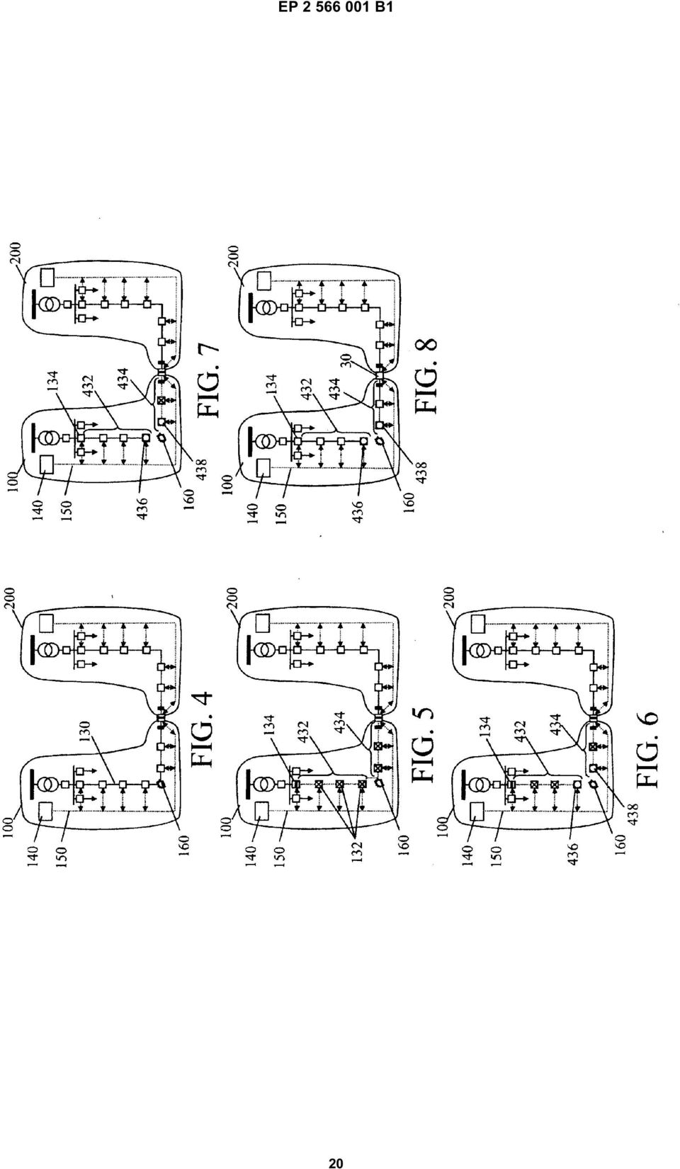
13 23 EP B1 24 (1), ansprechend darauf, dass ein Erster- Fehler-Unterbrechungsgerät ausgelöst wird, ausgeführt wird, ein Verfahren durchführt, das umfasst: Ermitteln eines Erster-Fehler-Orts eines ersten Fehlers (4); Instruieren eines IED, das einen Knoten stromaufwärts des Erster-Fehler-Orts steuert, Leitfähigkeit zwischen einer Quellenseite eines beeinträchtigten Segments der ersten Partition und dem Erster-Fehler-Ort zu stoppen; Instruieren eines IED, das einen Knoten stromabwärts des Erster-Fehler-Orts steuert, Leitfähigkeit zwischen dem Erster-Fehler-Ort und einem stromabwärtigen Bereich des beeinträchtigten Segments (6) zu unterbrechen; Wiederherstellen von Strom zu der Quellenseite des beeinträchtigten Segments (8), was ein Wiederherstellen von Leitfähigkeit durch das Erster-Fehler-Unterbrechungsgerät einschließt; Ermitteln eines Strombedarfs einer Last in dem stromabwärtigen Bereich des beeinträchtigten Segments, was ein Analysieren eines Strombedarfs des stromabwärtigen Bereichs einschließt; Ermitteln von Strom, der für den stromabwärtigen Bereich des beeinträchtigten Segments von mindestens einer Sekundärquelle verfügbar ist; ansprechend darauf, dass der Strombedarf die Stromverfügbarkeit übertrifft (312), Unterbrechen von Leitfähigkeit zu einem Bereich des stromabwärtigen Bereichs des beeinträchtigen Segments, um den Strombedarf zu verringern; Verbinden mindestens einer Sekundärquelle mit dem stromabwärtigen Bereich des beeinträchtigten Segments; und, ansprechend auf ein Zweiter-Fehler-Unterbrechungsgerät, das nach dem Verbinden der mindestens einen Sekundärquelle mit dem stromabwärtigen Bereich des beeinträchtigten Segments ausgelöst wird: 3 4 Ermitteln eines Ortes des Zweiter-Fehler-Unterbrechungsgeräts (04); Ermitteln eines Zweiter-Fehler-Orts des zweiten Fehlers (08); Isolieren des zweiten Fehlers (,, 36); Wiederherstellen von Strom stromaufwärts des Zweiter-Fehler-Orts (12, 32, 38); und Wiederherstellen von Strom stromabwärts des Zweiter-Fehler-Orts (28). 14. Stromverteilungsnetzwerk-Fehlermanagementsystem gemäß Anspruch 13, ferner umfassend ein erstes Verbindungsstück, das dafür eingerichtet ist, selektiv Leitfähigkeit zwischen der ersten Partition (0) und einer Sekundärquelle zu aktivieren, und wobei das Verbinden mindestens einer Sekundärquelle ein Aktivieren von Leitfähigkeit durch das erste Verbindungsstück einschließt. Revendications 1. Procédé mis en oeuvre par ordinateur de gestion de pannes de réseau de distribution d énergie (0, 00), le réseau de distribution d énergie () ayant une première partition (0) comprenant au moins un dispositif de commande (1) configuré pour exécuter le procédé à la suite d une panne (160) dans le réseau de distribution d énergie et une pluralité de noeuds (132) configurés pour communiquer avec le au moins un dispositif de commande et réagir à celuici, chaque dispositif de commande étant configuré pour stocker des données de réseau (142), notamment au moins l une ou l autre de données de dispositifs (144), de données de topologie (146) et de données de demande d énergie (148), le procédé comprenant les étapes consistant à : utiliser les données de réseau pour déterminer une région dans la première partition (0) affectée par une première panne (4) ; isoler la région affectée en instruisant un noeud amont le plus proche et un noeud aval le plus proche d interrompre la conductivité vers la région affectée (6) ; et restaurer l énergie en amont de la première panne (8), notamment restaurer la conductivité à travers un premier dispositif d interruption de panne entre une source et la région affectée, le premier dispositif d interruption de panne ayant une conductivité précédemment interrompue à la suite de la première panne ; caractérisé en ce que : 0 l on restaure l énergie en aval de la première panne (314) à la suite d un besoin d énergie et d une disponibilité d énergie, notamment on analyse le besoin en énergie et la disponibilité d énergie (3), on déconnecte une charge pour réduire le besoin en énergie lorsque l on détermine que la disponibilité d énergie n est pas supérieure au besoin en énergie avant de déconnecter la charge (318) et l on connecte au moins une source 13
 zu unterbrechen; Wiederherstellen von Strom zu der Quellenseite des beeinträchtigten Segments (8), was ein Wiederherstellen von Leitfähigkeit")
14 EP B1 26 secondaire à la région affectée en aval de la première panne (314) ; et dans lequel le réseau de distribution d énergie comprend en outre au moins une deuxième partition (0) avec un dispositif de commande respectif (2) ayant des données de réseau respectives (242) et le procédé mis en oeuvre par ordinateur comprend en outre, à la suite du déclenchement d un second dispositif d interruption de panne après connexion de la au moins une source secondaire à la partie aval du segment affecté (02) : la détermination d un emplacement du second dispositif d interruption de panne (04) ; la détermination d un second emplacement de panne pour la seconde panne (08) ; l isolement de la seconde panne (,, 36) ; la restauration de l énergie en amont du second emplacement de panne (12, 32, 38) ; et la restauration de l énergie en aval du second emplacement de panne (28). 2. Procédé mis en oeuvre par ordinateur selon la revendication 1, dans lequel au moins un dispositif de commande (1, 2) est configuré pour recevoir des données d au moins un dispositif sur le réseau en temps réel. 3. Procédé mis en oeuvre par ordinateur selon la revendication 1 ou la revendication 2, dans lequel la déconnexion de la charge comprend le choix prioritaire, entre une pluralité de charges, de celle à déconnecter. 4. Procédé mis en oeuvre par ordinateur selon la revendication 3, dans lequel la première partition (0) comprend au moins une liaison configurée pour connecter la première partition à au moins une source secondaire et, de préférence, au moins une première liaison de la au moins une liaison est une liaison normalement ouverte.. Procédé mis en oeuvre par ordinateur selon la revendication 3 ou la revendication 4, dans lequel le choix prioritaire entre une pluralité de charges comprend la détermination de priorités sur la base des données reçues d au moins une charge du réseau Procédé mis en oeuvre par ordinateur selon l une quelconque des revendications précédentes, dans lequel la détermination d un emplacement de la seconde panne (08) comprend : la détermination qu un second dispositif d interruption de panne a été déclenché ; et la détermination d un emplacement du second dispositif d interruption de panne. 7. Procédé mis en oeuvre par ordinateur selon l une quelconque des revendications précédentes, dans lequel la source secondaire comprend au moins la seconde partition (0), au moins les dispositifs de commande (1, 2) de la première et de la seconde partition étant configurés pour échanger sélectivement des informations comprenant au moins l un(e) d un besoin d énergie, d une disponibilité d énergie et d une information de panne respectifs. 8. Procédé mis en oeuvre par ordinateur selon l une quelconque des revendications précédentes, dans lequel, à la suite du positionnement du second dispositif d interruption de panne dans la seconde partition (0), la restauration de l énergie dans la partie amont comprend le second dispositif de commande (2) qui remet à zéro le second dispositif d interruption de panne et, à la suite du positionnement du second emplacement de panne dans la première partition (0), l isolement de la seconde panne comprend la déconnexion de la seconde partition de la première partition et le premier dispositif de commande (1) qui instruit au moins un dispositif électronique intelligent (IED) commandant un noeud immédiatement en amont et un noeud immédiatement en aval du second emplacement de panne d interrompre la conductivité vers l emplacement de la panne et la restauration de l énergie en aval du second emplacement de panne comprend la reconnexion de la seconde partition (0) avec la première partition (0). 9. Procédé mis en oeuvre par ordinateur selon l une quelconque des revendications précédentes, dans lequel, à la suite du second dispositif d interruption de panne qui se trouve dans la seconde partition (0), la restauration de l énergie dans la partie amont comprend le second dispositif de commande qui remet à zéro le second dispositif d interruption de panne et, à la suite du second emplacement de panne qui se trouve dans la seconde partition (0), l isolement de la seconde panne comprend le second dispositif de commande (2) qui instruit au moins un dispositif électronique intelligent (IED) commandant un noeud immédiatement en amont et un noeud immédiatement en aval du second emplacement de panne d interrompre la conductivité vers l emplacement de panne et la restauration de l énergie en aval du second emplacement de panne comprend, à la suite de la première panne qui a été ré- 14
 ; la détermination d un second emplacement de panne pour la seconde panne (08) ; l isolement de la seconde panne (,, 36) ; la restauration de l énergie en amont du second emplacement de panne")
15 27 EP B1 28 parée, le premier dispositif de commande (1) qui instruit au moins un IED commandant un noeud de la première partition (0) immédiatement en amont et un noeud de la première partition immédiatement en aval du premier emplacement de panne de permettre à nouveau la conductivité et de reconnecter la seconde partition (0) à la première partition (0).. Procédé mis en oeuvre par ordinateur selon l une quelconque des revendications précédentes, dans lequel, à la suite du second dispositif d interruption de panne qui se trouve dans la première partition (0), la restauration de l énergie dans la partie amont comprend le premier dispositif de commande (1) qui remet à zéro le second dispositif d interruption de panne et, à la suite du second emplacement de panne qui se trouve dans la partie amont de la première partition, l isolement de la seconde panne comprend le premier dispositif de commande qui instruit au moins un dispositif électronique intelligent (IED) immédiatement en amont et au moins un dispositif électronique intelligent (IED) immédiatement en aval du second emplacement de panne d interrompre la conductivité vers l emplacement de panne et la restauration de l énergie en aval du second emplacement de panne comprend, à la suite de la première panne qui a été réparée, le premier dispositif de commande (1) qui instruit au moins un dispositif électronique intelligent (IED) qui commande un noeud de la première partition (0) immédiatement en amont et un noeud de la première partition immédiatement en aval du premier emplacement de panne de permettre à nouveau la conductivité. 11. Procédé mis en oeuvre par ordinateur selon l une quelconque des revendications précédentes, dans lequel la restauration de l énergie en aval du second emplacement de panne comprend : la détermination d un besoin en énergie d une charge en aval du second emplacement de panne ; la détermination d une énergie disponible pour une charge en aval du second emplacement de panne ; et, à la suite du besoin en énergie qui dépasse la disponibilité en énergie, l arrêt de la conductivité vers la charge en aval du second emplacement de panne pour réduire le besoin en énergie. 12. Produit de programme informatique comprenant un code de programme mis en oeuvre dans au moins un support lisible sur ordinateur qui, lorsqu il est exécuté, permet à un système informatique de mettre en oeuvre un procédé de gestion de panne dans un réseau de distribution d énergie comprenant au moins une partition (0) avec au moins un premier dispositif de commande (1) configuré pour exécuter le procédé à la suite d au moins une panne dans le réseau de distribution d énergie (), une pluralité de noeuds (132) configurés pour communiquer avec le au moins un dispositif de commande et réagir à celui-ci, chaque dispositif de commande étant configuré pour stocker des données de réseau, notamment au moins l une d entre des données de dispositifs, des données de topologie et des données de demande d énergie, le produit de programme informatique comprenant le code de programme pour effectuer le procédé mis en oeuvre par ordinateur selon l une quelconque des revendications 1 à Système de gestion de pannes d un réseau de distribution d énergie, comprenant : au moins un dispositif de commande (1) de première partition comprenant au moins un dispositif de calcul, le dispositif de commande de la première partition étant configuré pour communiquer avec au moins un dispositif électronique intelligent dénommé IED ci-dessus, configuré pour commander la conductivité dans une première partition (0) d un réseau de distribution d énergie (), le dispositif de commande (1) de la première partition étant également configuré pour stocker des données de réseau, notamment des données provenant de la au moins une IED et pour envoyer une instruction à la au moins une IED ; au moins un dispositif d interruption de panne qui réagit à la au moins une IED ; et un programme d ordinateur comprenant un code lisible sur ordinateur qui, lorsqu il est exécuté par un dispositif de calcul du dispositif de commande (1) de la première partition, à la suite du déclenchement d un premier dispositif d interruption de panne, effectue un procédé comprenant les étapes consistant à : déterminer un premier emplacement de panne pour une première panne (4) ; instruire une IED commandant un noeud en amont du premier emplacement de panne de stopper la conductivité entre un côté source d un segment affecté de la première partition et le premier emplacement de panne ; instruire une IED commandant un noeud en aval du premier emplacement de panne d interrompre la conductivité entre le premier emplacement de panne et une partie aval du segment affecté (6) ; restaurer l énergie du côté source du segment affecté (8), notamment restaurer la conducti-
, la restauration de l énergie dans la partie amont comprend le premier dispositif de commande (1) qui remet à zéro le second dispositif d interruption de panne et, à la suite du second")
16 29 EP B1 vité à travers le premier dispositif d interruption de panne ; déterminer un besoin en énergie d une charge sur la partie aval du segment affecté, notamment analyser un besoin en énergie de la partie aval ; déterminer l énergie disponible sur la partie aval du segment affecté à partir d au moins une source secondaire ; à la suite du besoin en énergie qui dépasse la disponibilité d énergie (312), interrompre la conductivité dans une partie de la partie aval du segment affecté pour réduire le besoin en énergie ; connecter au moins une source secondaire à la partie aval du segment affecté ; et, à la suite d un second dispositif d interruption de panne qui est déclenché après connexion de la au moins une source secondaire à la partie aval du segment affecté : déterminer un emplacement du second dispositif d interruption de panne (04) ; déterminer un second emplacement de panne pour la seconde panne (08) ; isoler la seconde panne (,, 36) ; restaurer l énergie en amont du second emplacement de panne (12, 32, 38) ; et restaurer l énergie en aval du second emplacement de panne (28). 14. Système de gestion de panne de réseau de distribution d énergie selon la revendication 13, comprenant en outre une première liaison configurée pour permettre sélectivement la conductivité entre la première partition (0) et une source secondaire et dans lequel la connexion d au moins une source secondaire comprend de permettre la conductivité à travers la première liaison

17 EP B1 17

18 EP B1 18

19 EP B1 19

20 EP B1
EP 2 455 926 A1 (19) (11) EP 2 455 926 A1 (12) EUROPEAN PATENT APPLICATION. (43) Date of publication: 23.05.2012 Bulletin 2012/21
 (11) EP 2 455 926 A1 (12) EUROPEAN PATENT APPLICATION. (43) Date of publication: 23.05.2012 Bulletin 2012/21") (19) (12) EUROPEAN PATENT APPLICATION (11) EP 2 4 926 A1 (43) Date of publication: 23.0.2012 Bulletin 2012/21 (21) Application number: 11190024.7 (1) Int Cl.: G08B 2/14 (2006.01) G08B 2/00 (2006.01) G0B
(19) (12) EUROPEAN PATENT APPLICATION (11) EP 2 4 926 A1 (43) Date of publication: 23.0.2012 Bulletin 2012/21 (21) Application number: 11190024.7 (1) Int Cl.: G08B 2/14 (2006.01) G08B 2/00 (2006.01) G0B
TEPZZ 87_546A T EP 2 871 546 A2 (19) (11) EP 2 871 546 A2 (12) EUROPEAN PATENT APPLICATION. (51) Int Cl.: G05B 19/05 (2006.01)
 (11) EP 2 871 546 A2 (12) EUROPEAN PATENT APPLICATION. (51) Int Cl.: G05B 19/05 (2006.01)") (19) TEPZZ 87_46A T (11) EP 2 871 46 A2 (12) EUROPEAN PATENT APPLICATION (43) Date of publication: 13.0.1 Bulletin 1/ (1) Int Cl.: G0B 19/0 (06.01) (21) Application number: 14188238.1 (22) Date of filing:
(19) TEPZZ 87_46A T (11) EP 2 871 46 A2 (12) EUROPEAN PATENT APPLICATION (43) Date of publication: 13.0.1 Bulletin 1/ (1) Int Cl.: G0B 19/0 (06.01) (21) Application number: 14188238.1 (22) Date of filing:
TEPZZ 9 Z5A_T EP 2 922 305 A1 (19) (11) EP 2 922 305 A1. (12) EUROPEAN PATENT APPLICATION published in accordance with Art.
 (11) EP 2 922 305 A1. (12) EUROPEAN PATENT APPLICATION published in accordance with Art.") (19) TEPZZ 9 ZA_T (11) EP 2 922 A1 (12) EUROPEAN PATENT APPLICATION published in accordance with Art. 13(4) EPC (43) Date of publication: 23.09.1 Bulletin 1/39 (21) Application number: 1386446.2 (22) Date
(19) TEPZZ 9 ZA_T (11) EP 2 922 A1 (12) EUROPEAN PATENT APPLICATION published in accordance with Art. 13(4) EPC (43) Date of publication: 23.09.1 Bulletin 1/39 (21) Application number: 1386446.2 (22) Date
TEPZZ 68575_A_T EP 2 685 751 A1 (19) (11) EP 2 685 751 A1. (12) EUROPEAN PATENT APPLICATION published in accordance with Art.
 (11) EP 2 685 751 A1. (12) EUROPEAN PATENT APPLICATION published in accordance with Art.") (19) TEPZZ 687_A_T (11) EP 2 68 71 A1 (12) EUROPEAN PATENT APPLICATION published in accordance with Art. 3(4) EPC (43) Date of publication:.01.14 Bulletin 14/03 (21) Application number: 1278849.6 (22)
(19) TEPZZ 687_A_T (11) EP 2 68 71 A1 (12) EUROPEAN PATENT APPLICATION published in accordance with Art. 3(4) EPC (43) Date of publication:.01.14 Bulletin 14/03 (21) Application number: 1278849.6 (22)
TEPZZ 6_Z76 A_T EP 2 610 763 A1 (19) (11) EP 2 610 763 A1 (12) EUROPEAN PATENT APPLICATION. (51) Int Cl.:
 (11) EP 2 610 763 A1 (12) EUROPEAN PATENT APPLICATION. (51) Int Cl.:") (19) TEPZZ 6_Z76 A_T (11) EP 2 6 763 A1 (12) EUROPEAN PATENT APPLICATION (43) Date of publication: 03.07.2013 Bulletin 2013/27 (51) Int Cl.: G06F 17/30 (2006.01) (21) Application number: 12192220.7 (22)
(19) TEPZZ 6_Z76 A_T (11) EP 2 6 763 A1 (12) EUROPEAN PATENT APPLICATION (43) Date of publication: 03.07.2013 Bulletin 2013/27 (51) Int Cl.: G06F 17/30 (2006.01) (21) Application number: 12192220.7 (22)
TEPZZ 94Z968A_T EP 2 940 968 A1 (19) (11) EP 2 940 968 A1 (12) EUROPEAN PATENT APPLICATION. (51) Int Cl.: H04L 29/08 (2006.01)
 (11) EP 2 940 968 A1 (12) EUROPEAN PATENT APPLICATION. (51) Int Cl.: H04L 29/08 (2006.01)") (19) TEPZZ 94Z968A_T (11) EP 2 940 968 A1 (12) EUROPEAN PATENT APPLICATION (43) Date of publication: 04.11.20 Bulletin 20/4 (1) Int Cl.: H04L 29/08 (2006.01) (21) Application number: 1430649.7 (22) Date
(19) TEPZZ 94Z968A_T (11) EP 2 940 968 A1 (12) EUROPEAN PATENT APPLICATION (43) Date of publication: 04.11.20 Bulletin 20/4 (1) Int Cl.: H04L 29/08 (2006.01) (21) Application number: 1430649.7 (22) Date
TEPZZ 65Z79 A_T EP 2 650 793 A1 (19) (11) EP 2 650 793 A1. (12) EUROPEAN PATENT APPLICATION published in accordance with Art.
 (11) EP 2 650 793 A1. (12) EUROPEAN PATENT APPLICATION published in accordance with Art.") (19) TEPZZ 65Z79 A_T (11) EP 2 650 793 A1 (12) EUROPEAN PATENT APPLICATION published in accordance with Art. 153(4) EPC (43) Date of publication: 16.10.2013 Bulletin 2013/42 (21) Application number: 12818771.3
(19) TEPZZ 65Z79 A_T (11) EP 2 650 793 A1 (12) EUROPEAN PATENT APPLICATION published in accordance with Art. 153(4) EPC (43) Date of publication: 16.10.2013 Bulletin 2013/42 (21) Application number: 12818771.3
EP 2 365 669 A1 (19) (11) EP 2 365 669 A1 (12) EUROPEAN PATENT APPLICATION. (43) Date of publication: 14.09.2011 Bulletin 2011/37
 (11) EP 2 365 669 A1 (12) EUROPEAN PATENT APPLICATION. (43) Date of publication: 14.09.2011 Bulletin 2011/37") (19) (12) EUROPEAN PATENT APPLICATION (11) EP 2 36 669 A1 (43) Date of publication: 14.09.11 Bulletin 11/37 (1) Int Cl.: H04L 12/8 (06.01) (21) Application number: 00243.6 (22) Date of filing:.03. (84)
(19) (12) EUROPEAN PATENT APPLICATION (11) EP 2 36 669 A1 (43) Date of publication: 14.09.11 Bulletin 11/37 (1) Int Cl.: H04L 12/8 (06.01) (21) Application number: 00243.6 (22) Date of filing:.03. (84)
TEPZZ 69 49A_T EP 2 693 349 A1 (19) (11) EP 2 693 349 A1 (12) EUROPEAN PATENT APPLICATION. (51) Int Cl.: G06F 17/30 (2006.01)
 (11) EP 2 693 349 A1 (12) EUROPEAN PATENT APPLICATION. (51) Int Cl.: G06F 17/30 (2006.01)") (19) TEPZZ 69 49A_T (11) EP 2 693 349 A1 (12) EUROPEAN PATENT APPLICATION (43) Date of publication: 0.02.2014 Bulletin 2014/06 (1) Int Cl.: G06F 17/30 (2006.01) (21) Application number: 13160696.4 (22)
(19) TEPZZ 69 49A_T (11) EP 2 693 349 A1 (12) EUROPEAN PATENT APPLICATION (43) Date of publication: 0.02.2014 Bulletin 2014/06 (1) Int Cl.: G06F 17/30 (2006.01) (21) Application number: 13160696.4 (22)
TEPZZ 88_898A_T EP 2 881 898 A1 (19) (11) EP 2 881 898 A1 (12) EUROPEAN PATENT APPLICATION. (51) Int Cl.: G06N 5/04 (2006.01) G06F 17/30 (2006.
 (11) EP 2 881 898 A1 (12) EUROPEAN PATENT APPLICATION. (51) Int Cl.: G06N 5/04 (2006.01) G06F 17/30 (2006.") (19) TEPZZ 88_898A_T (11) EP 2 881 898 A1 (12) EUROPEAN PATENT APPLICATION (43) Date of publication:.06. Bulletin /24 (1) Int Cl.: G06N /04 (06.01) G06F 17/ (06.01) (21) Application number: 136680.3 (22)
(19) TEPZZ 88_898A_T (11) EP 2 881 898 A1 (12) EUROPEAN PATENT APPLICATION (43) Date of publication:.06. Bulletin /24 (1) Int Cl.: G06N /04 (06.01) G06F 17/ (06.01) (21) Application number: 136680.3 (22)
TEPZZ 87657ZA_T EP 2 876 570 A1 (19) (11) EP 2 876 570 A1 (12) EUROPEAN PATENT APPLICATION
 (11) EP 2 876 570 A1 (12) EUROPEAN PATENT APPLICATION") (19) TEPZZ 8767ZA_T (11) EP 2 876 70 A1 (12) EUROPEAN PATENT APPLICATION (43) Date of publication: 27.0.201 Bulletin 201/22 (21) Application number: 14189809.8 (1) Int Cl.: G06F 21/34 (2013.01) G08B 13/196
(19) TEPZZ 8767ZA_T (11) EP 2 876 70 A1 (12) EUROPEAN PATENT APPLICATION (43) Date of publication: 27.0.201 Bulletin 201/22 (21) Application number: 14189809.8 (1) Int Cl.: G06F 21/34 (2013.01) G08B 13/196
TEPZZ 84 587A_T EP 2 843 587 A1 (19) (11) EP 2 843 587 A1 (12) EUROPEAN PATENT APPLICATION. (51) Int Cl.: G06F 21/64 (2013.01)
 (11) EP 2 843 587 A1 (12) EUROPEAN PATENT APPLICATION. (51) Int Cl.: G06F 21/64 (2013.01)") (19) TEPZZ 84 87A_T (11) EP 2 843 87 A1 (12) EUROPEAN PATENT APPLICATION (43) Date of publication: 04.03.201 Bulletin 201/ (1) Int Cl.: G06F 21/64 (2013.01) (21) Application number: 13181902.1 (22) Date
(19) TEPZZ 84 87A_T (11) EP 2 843 87 A1 (12) EUROPEAN PATENT APPLICATION (43) Date of publication: 04.03.201 Bulletin 201/ (1) Int Cl.: G06F 21/64 (2013.01) (21) Application number: 13181902.1 (22) Date
(51) Int Cl.: G06F 9/455 (2006.01) G06F 9/50 (2006.01)
 Int Cl.: G06F 9/455 (2006.01) G06F 9/50 (2006.01)") (19) TEPZZ 6987 B_T (11) EP 2 698 711 B1 (12) EUROPEAN PATENT SPECIFICATION (4) Date of publication and mention of the grant of the patent: 0.08.1 Bulletin 1/32 (21) Application number: 118777.8 (22) Date
(19) TEPZZ 6987 B_T (11) EP 2 698 711 B1 (12) EUROPEAN PATENT SPECIFICATION (4) Date of publication and mention of the grant of the patent: 0.08.1 Bulletin 1/32 (21) Application number: 118777.8 (22) Date
EP 2 492 881 A2 (19) (11) EP 2 492 881 A2 (12) EUROPEAN PATENT APPLICATION. (43) Date of publication: 29.08.2012 Bulletin 2012/35
 (11) EP 2 492 881 A2 (12) EUROPEAN PATENT APPLICATION. (43) Date of publication: 29.08.2012 Bulletin 2012/35") (19) (12) EUROPEAN PATENT APPLICATION (11) EP 2 492 881 A2 (43) Date of publication: 29.08.2012 Bulletin 2012/35 (51) Int Cl.: G08B 13/16 (2006.01) G08B 25/08 (2006.01) (21) Application number: 12386006.6
(19) (12) EUROPEAN PATENT APPLICATION (11) EP 2 492 881 A2 (43) Date of publication: 29.08.2012 Bulletin 2012/35 (51) Int Cl.: G08B 13/16 (2006.01) G08B 25/08 (2006.01) (21) Application number: 12386006.6
TEPZZ 96 A_T EP 2 961 111 A1 (19) (11) EP 2 961 111 A1. (12) EUROPEAN PATENT APPLICATION published in accordance with Art.
 (11) EP 2 961 111 A1. (12) EUROPEAN PATENT APPLICATION published in accordance with Art.") (19) TEPZZ 96 A_T (11) EP 2 961 111 A1 (12) EUROPEAN PATENT APPLICATION published in accordance with Art. 13(4) EPC (43) Date of publication:.12.1 Bulletin 1/3 (21) Application number: 147426.7 (22) Date
(19) TEPZZ 96 A_T (11) EP 2 961 111 A1 (12) EUROPEAN PATENT APPLICATION published in accordance with Art. 13(4) EPC (43) Date of publication:.12.1 Bulletin 1/3 (21) Application number: 147426.7 (22) Date
*EP001520563A1* EP 1 520 563 A1 (19) (11) EP 1 520 563 A1 (12) EUROPEAN PATENT APPLICATION. (43) Date of publication: 06.04.2005 Bulletin 2005/14
 (11) EP 1 520 563 A1 (12) EUROPEAN PATENT APPLICATION. (43) Date of publication: 06.04.2005 Bulletin 2005/14") (19) Europäisches Patentamt European Patent Office Office européen des brevets *EP001520563A1* (11) EP 1 520 563 A1 (12) EUROPEAN PATENT APPLICATION (43) Date of publication: 06.04.2005 Bulletin 2005/14
(19) Europäisches Patentamt European Patent Office Office européen des brevets *EP001520563A1* (11) EP 1 520 563 A1 (12) EUROPEAN PATENT APPLICATION (43) Date of publication: 06.04.2005 Bulletin 2005/14
EP 2 922 249 A1 (19) (11) EP 2 922 249 A1 (12) EUROPEAN PATENT APPLICATION. (43) Date of publication: 23.09.2015 Bulletin 2015/39
 (11) EP 2 922 249 A1 (12) EUROPEAN PATENT APPLICATION. (43) Date of publication: 23.09.2015 Bulletin 2015/39") (19) TEPZZ 9 49A_T (11) EP 2 922 249 A1 (12) EUROPEAN PATENT APPLICATION (43) Date of publication: 23.09. Bulletin /39 (21) Application number: 16003.0 (1) Int Cl.: H04L 12/7 (13.01) H04L 12/717 (13.01)
(19) TEPZZ 9 49A_T (11) EP 2 922 249 A1 (12) EUROPEAN PATENT APPLICATION (43) Date of publication: 23.09. Bulletin /39 (21) Application number: 16003.0 (1) Int Cl.: H04L 12/7 (13.01) H04L 12/717 (13.01)
TEPZZ 8898 7A_T EP 2 889 827 A1 (19) (11) EP 2 889 827 A1 (12) EUROPEAN PATENT APPLICATION. (51) Int Cl.: G06Q 40/04 (2012.01)
 (11) EP 2 889 827 A1 (12) EUROPEAN PATENT APPLICATION. (51) Int Cl.: G06Q 40/04 (2012.01)") (19) TEPZZ 8898 7A_T (11) EP 2 889 827 A1 (12) EUROPEAN PATENT APPLICATION (43) Date of publication: 01.07.201 Bulletin 201/27 (1) Int Cl.: G06Q 40/04 (2012.01) (21) Application number: 14199864.1 (22)
(19) TEPZZ 8898 7A_T (11) EP 2 889 827 A1 (12) EUROPEAN PATENT APPLICATION (43) Date of publication: 01.07.201 Bulletin 201/27 (1) Int Cl.: G06Q 40/04 (2012.01) (21) Application number: 14199864.1 (22)
(51) Int Cl.: H04L 12/56 (2006.01)
 Int Cl.: H04L 12/56 (2006.01)") (19) (11) EP 1 779 90 B1 (12) EUROPEAN PATENT SPECIFICATION (4) Date of publication and mention of the grant of the patent: 28.12.11 Bulletin 11/2 (21) Application number: 0783482.2 (22) Date of filing:
(19) (11) EP 1 779 90 B1 (12) EUROPEAN PATENT SPECIFICATION (4) Date of publication and mention of the grant of the patent: 28.12.11 Bulletin 11/2 (21) Application number: 0783482.2 (22) Date of filing:
(51) Int Cl.: G10L 15/26 (2006.01)
 Int Cl.: G10L 15/26 (2006.01)") (19) TEPZZ Z 8B_T (11) EP 2 023 338 B1 (12) EUROPEAN PATENT SPECIFICATION (4) Date of publication and mention of the grant of the patent: 28.0.14 Bulletin 14/22 (1) Int Cl.: GL /26 (06.01) (21) Application
(19) TEPZZ Z 8B_T (11) EP 2 023 338 B1 (12) EUROPEAN PATENT SPECIFICATION (4) Date of publication and mention of the grant of the patent: 28.0.14 Bulletin 14/22 (1) Int Cl.: GL /26 (06.01) (21) Application
(51) Int Cl.: G06F 11/14 (2006.01)
 Int Cl.: G06F 11/14 (2006.01)") (19) (12) EUROPEAN PATENT SPECIFICATION (11) EP 1 08 414 B1 (4) Date of publication and mention of the grant of the patent: 04.03.09 Bulletin 09/ (1) Int Cl.: G06F 11/14 (06.01) (21) Application number:
(19) (12) EUROPEAN PATENT SPECIFICATION (11) EP 1 08 414 B1 (4) Date of publication and mention of the grant of the patent: 04.03.09 Bulletin 09/ (1) Int Cl.: G06F 11/14 (06.01) (21) Application number:
TEPZZ 79ZZ8_A_T EP 2 790 081 A1 (19) (11) EP 2 790 081 A1 (12) EUROPEAN PATENT APPLICATION. (43) Date of publication: 15.10.2014 Bulletin 2014/42
 (11) EP 2 790 081 A1 (12) EUROPEAN PATENT APPLICATION. (43) Date of publication: 15.10.2014 Bulletin 2014/42") (19) TEPZZ 79ZZ8_A_T (11) EP 2 790 081 A1 (12) EUROPEAN PATENT APPLICATION (43) Date of publication: 1..14 Bulletin 14/42 (1) Int Cl.: G0D 23/19 (06.01) (21) Application number: 1414221.7 (22) Date of
(19) TEPZZ 79ZZ8_A_T (11) EP 2 790 081 A1 (12) EUROPEAN PATENT APPLICATION (43) Date of publication: 1..14 Bulletin 14/42 (1) Int Cl.: G0D 23/19 (06.01) (21) Application number: 1414221.7 (22) Date of
Title (fr) SOURCE IONIQUE INTERNE DOUBLE POUR PRODUCTION DE FAISCEAU DE PARTICULES AVEC UN CYCLOTRON
 SOURCE IONIQUE INTERNE DOUBLE POUR PRODUCTION DE FAISCEAU DE PARTICULES AVEC UN CYCLOTRON") Title (en) A TWIN INTERNAL ION SOURCE FOR PARTICLE BEAM PRODUCTION WITH A CYCLOTRON Title (de) DOPPELTE INTERNE IONENQUELLE FÜR PARTIKELSTRAHLHERSTELLUNG MIT EINEM ZYKLOTRON Title (fr) SOURCE IONIQUE INTERNE
Title (en) A TWIN INTERNAL ION SOURCE FOR PARTICLE BEAM PRODUCTION WITH A CYCLOTRON Title (de) DOPPELTE INTERNE IONENQUELLE FÜR PARTIKELSTRAHLHERSTELLUNG MIT EINEM ZYKLOTRON Title (fr) SOURCE IONIQUE INTERNE
(51) Int Cl.: H04N 7/52 (2011.01)
 Int Cl.: H04N 7/52 (2011.01)") (19) TEPZZ_9776 B_T (11) EP 1 977 611 B1 (12) EUROPEAN PATENT SPECIFICATION (4) Date of publication and mention of the grant of the patent: 16.01.13 Bulletin 13/03 (21) Application number: 0683819.1 (22)
(19) TEPZZ_9776 B_T (11) EP 1 977 611 B1 (12) EUROPEAN PATENT SPECIFICATION (4) Date of publication and mention of the grant of the patent: 16.01.13 Bulletin 13/03 (21) Application number: 0683819.1 (22)
(51) Int Cl.: H04L 9/32 (2006.01) G09C 1/00 (2006.01) G06F 21/33 (2013.01) H04L 29/06 (2006.01)
 Int Cl.: H04L 9/32 (2006.01) G09C 1/00 (2006.01) G06F 21/33 (2013.01) H04L 29/06 (2006.01)") (19) TEPZZ Z48B_T (11) EP 2 2 048 B1 (12) EUROPEAN PATENT SPECIFICATION (4) Date of publication and mention of the grant of the patent: 13.0. Bulletin / (21) Application number: 1179238.6 (22) Date of
(19) TEPZZ Z48B_T (11) EP 2 2 048 B1 (12) EUROPEAN PATENT SPECIFICATION (4) Date of publication and mention of the grant of the patent: 13.0. Bulletin / (21) Application number: 1179238.6 (22) Date of
TEPZZ 69 _ZA T EP 2 692 310 A2 (19) (11) EP 2 692 310 A2. (12) EUROPEAN PATENT APPLICATION published in accordance with Art.
 (11) EP 2 692 310 A2. (12) EUROPEAN PATENT APPLICATION published in accordance with Art.") (19) TEPZZ 69 _ZA T (11) EP 2 692 3 A2 (12) EUROPEAN PATENT APPLICATION published in accordance with Art. 13(4) EPC (43) Date of publication: 0.02.14 Bulletin 14/06 (21) Application number: 1276632.0 (22)
(19) TEPZZ 69 _ZA T (11) EP 2 692 3 A2 (12) EUROPEAN PATENT APPLICATION published in accordance with Art. 13(4) EPC (43) Date of publication: 0.02.14 Bulletin 14/06 (21) Application number: 1276632.0 (22)
Our patent and trade mark attorneys are here to help you protect and profit from your ideas, making sure they re working every bit as hard as you do.
 Our patent and trade mark attorneys are here to help you protect and profit from your ideas, making sure they re working every bit as hard as you do. Our people work with everyone from multi-nationals
TEPZZ 9 _88_A_T EP 2 921 881 A1 (19) (11) EP 2 921 881 A1 (12) EUROPEAN PATENT APPLICATION
 (11) EP 2 921 881 A1 (12) EUROPEAN PATENT APPLICATION") (19) TEPZZ 9 _88_A_T (11) EP 2 921 881 A1 (12) EUROPEAN PATENT APPLICATION (43) Date of publication: 23.09.1 Bulletin 1/39 (21) Application number: 1416041.2 (1) Int Cl.: G01T 1/ (06.01) G03B 42/02 (06.01)
(19) TEPZZ 9 _88_A_T (11) EP 2 921 881 A1 (12) EUROPEAN PATENT APPLICATION (43) Date of publication: 23.09.1 Bulletin 1/39 (21) Application number: 1416041.2 (1) Int Cl.: G01T 1/ (06.01) G03B 42/02 (06.01)
EP 1 675 420 A1 (19) (11) EP 1 675 420 A1 (12) EUROPEAN PATENT APPLICATION. (43) Date of publication: 28.06.2006 Bulletin 2006/26
 (11) EP 1 675 420 A1 (12) EUROPEAN PATENT APPLICATION. (43) Date of publication: 28.06.2006 Bulletin 2006/26") (19) Europäisches Patentamt European Patent Office Office européen des brevets (12) EUROPEAN PATENT APPLICATION (11) EP 1 67 4 A1 (43) Date of publication: 28.06.06 Bulletin 06/26 (1) Int Cl.: H04Q 7/34
(19) Europäisches Patentamt European Patent Office Office européen des brevets (12) EUROPEAN PATENT APPLICATION (11) EP 1 67 4 A1 (43) Date of publication: 28.06.06 Bulletin 06/26 (1) Int Cl.: H04Q 7/34
EP 2 354 708 A2 (19) (11) EP 2 354 708 A2 (12) EUROPEAN PATENT APPLICATION. (43) Date of publication: 10.08.2011 Bulletin 2011/32
 (11) EP 2 354 708 A2 (12) EUROPEAN PATENT APPLICATION. (43) Date of publication: 10.08.2011 Bulletin 2011/32") (19) (12) EUROPEAN PATENT APPLICATION (11) EP 2 354 708 A2 (43) Date of publication:.08.2011 Bulletin 2011/32 (51) Int Cl.: F24H 3/08 (2006.01) F24H 8/00 (2006.01) (21) Application number: 111536.8 (22)
(19) (12) EUROPEAN PATENT APPLICATION (11) EP 2 354 708 A2 (43) Date of publication:.08.2011 Bulletin 2011/32 (51) Int Cl.: F24H 3/08 (2006.01) F24H 8/00 (2006.01) (21) Application number: 111536.8 (22)
EUROPEAN PATENT APPLICATION. Hudson, NC 28638 (US) Chancery Lane London WC2A 1QU (GB)
 Chancery Lane London WC2A 1QU (GB)") (19) (12) Europaisches Patentamt European Patent Office Office europeen een des brevets EUROPEAN PATENT APPLICATION EP 0 889 344 A1 (43) Date of publication: (51) nt CI.6: G 02 B 6/44 07.01.1999 Bulletin
(19) (12) Europaisches Patentamt European Patent Office Office europeen een des brevets EUROPEAN PATENT APPLICATION EP 0 889 344 A1 (43) Date of publication: (51) nt CI.6: G 02 B 6/44 07.01.1999 Bulletin
(51) Int Cl.: G06F 11/14 (2006.01) G06F 12/08 (2006.01)
 Int Cl.: G06F 11/14 (2006.01) G06F 12/08 (2006.01)") (19) TEPZZ 488949B_T (11) EP 2 488 949 B1 (12) EUROPEAN PATENT SPECIFICATION (4) Date of publication and mention of the grant of the patent: 07.0.14 Bulletin 14/19 (21) Application number: 76367.4 (22)
(19) TEPZZ 488949B_T (11) EP 2 488 949 B1 (12) EUROPEAN PATENT SPECIFICATION (4) Date of publication and mention of the grant of the patent: 07.0.14 Bulletin 14/19 (21) Application number: 76367.4 (22)
(51) Int Cl.: H04L 29/06 (2006.01) H04M 15/00 (2006.01)
 Int Cl.: H04L 29/06 (2006.01) H04M 15/00 (2006.01)") (19) TEPZZ 7Z 74 B_T (11) EP 2 702 742 B1 (12) EUROPEAN PATENT SPECIFICATION (4) Date of publication and mention of the grant of the patent:.04. Bulletin /16 (21) Application number: 1171674.6 (22) Date
(19) TEPZZ 7Z 74 B_T (11) EP 2 702 742 B1 (12) EUROPEAN PATENT SPECIFICATION (4) Date of publication and mention of the grant of the patent:.04. Bulletin /16 (21) Application number: 1171674.6 (22) Date
(51) Int Cl.: B29C 41/20 (2006.01) F21S 4/00 (2006.01) H05K 3/28 (2006.01)
 Int Cl.: B29C 41/20 (2006.01) F21S 4/00 (2006.01) H05K 3/28 (2006.01)") (19) TEPZZ 68698B_T (11) EP 2 68 698 B1 (12) EUROPEAN PATENT SPECIFICATION (4) Date of publication and mention of the grant of the patent: 18.11.201 Bulletin 201/47 (21) Application number: 11808612.3
(19) TEPZZ 68698B_T (11) EP 2 68 698 B1 (12) EUROPEAN PATENT SPECIFICATION (4) Date of publication and mention of the grant of the patent: 18.11.201 Bulletin 201/47 (21) Application number: 11808612.3
(51) Int Cl.: H04L 12/58 (2006.01) H04L 29/06 (2006.01)
 Int Cl.: H04L 12/58 (2006.01) H04L 29/06 (2006.01)") (19) TEPZZ_986 8 B_T (11) EP 1 986 382 B1 (12) EUROPEAN PATENT SPECIFICATION (4) Date of publication and mention of the grant of the patent: 19.02.14 Bulletin 14/08 (1) Int Cl.: H04L 12/8 (06.01) H04L
(19) TEPZZ_986 8 B_T (11) EP 1 986 382 B1 (12) EUROPEAN PATENT SPECIFICATION (4) Date of publication and mention of the grant of the patent: 19.02.14 Bulletin 14/08 (1) Int Cl.: H04L 12/8 (06.01) H04L
(51) Int Cl.: G06F 11/14 (2006.01) G06F 17/30 (2006.01)
 Int Cl.: G06F 11/14 (2006.01) G06F 17/30 (2006.01)") (19) TEPZZ_97799B_T (11) EP 1 97 799 B1 (12) EUROPEAN PATENT SPECIFICATION (4) Date of publication and mention of the grant of the patent: 06.0. Bulletin /19 (1) Int Cl.: G06F 11/14 (06.01) G06F 17/ (06.01)
(19) TEPZZ_97799B_T (11) EP 1 97 799 B1 (12) EUROPEAN PATENT SPECIFICATION (4) Date of publication and mention of the grant of the patent: 06.0. Bulletin /19 (1) Int Cl.: G06F 11/14 (06.01) G06F 17/ (06.01)
*EP001173363B1* EP 1 173 363 B1 (19) (11) EP 1 173 363 B1 (12) EUROPEAN PATENT SPECIFICATION
 (11) EP 1 173 363 B1 (12) EUROPEAN PATENT SPECIFICATION") (19) Europäisches Patentamt European Patent Office Office européen des brevets *EP001173363B1* (11) EP 1 173 363 B1 (12) EUROPEAN PATENT SPECIFICATION (4) Date of publication and mention of the grant of
(19) Europäisches Patentamt European Patent Office Office européen des brevets *EP001173363B1* (11) EP 1 173 363 B1 (12) EUROPEAN PATENT SPECIFICATION (4) Date of publication and mention of the grant of
EUROPEAN PATENT SPECIFICATION. (51) IntCL: G06F 13/10< 200B 1 > G06F 13/42( 2 OO 601 > (56) References cited: WO-A-97/19402 US-A- 6 085 265
 IntCL: G06F 13/10< 200B 1 > G06F 13/42( 2 OO 601 > (56) References cited: WO-A-97/19402 US-A- 6 085 265") (19) J Europäisches Patentamt European Patent Office Office européen des brevets (H) EP 1246 071 B1 (12) EUROPEAN PATENT SPECIFICATION (45) Date of publication and mention of the grant of the patent: 10.05.2006
(19) J Europäisches Patentamt European Patent Office Office européen des brevets (H) EP 1246 071 B1 (12) EUROPEAN PATENT SPECIFICATION (45) Date of publication and mention of the grant of the patent: 10.05.2006
*EP001139245A1* EP 1 139 245 A1 (19) (11) EP 1 139 245 A1 (12) EUROPEAN PATENT APPLICATION. (43) Date of publication: 04.10.2001 Bulletin 2001/40
 (11) EP 1 139 245 A1 (12) EUROPEAN PATENT APPLICATION. (43) Date of publication: 04.10.2001 Bulletin 2001/40") (19) Europäisches Patentamt European Patent Office Office européen des brevets *EP00113924A1* (11) EP 1 139 24 A1 (12) EUROPEAN PATENT APPLICATION (43) Date of publication: 04..01 Bulletin 01/ (1) Int
(19) Europäisches Patentamt European Patent Office Office européen des brevets *EP00113924A1* (11) EP 1 139 24 A1 (12) EUROPEAN PATENT APPLICATION (43) Date of publication: 04..01 Bulletin 01/ (1) Int
(51) Int Cl.: G01C 21/36 (2006.01)
 Int Cl.: G01C 21/36 (2006.01)") (19) TEPZZ_ 678B_T (11) EP 1 26 78 B1 (12) EUROPEAN PATENT SPECIFICATION (4) Date of publication and mention of the grant of the patent:.09.14 Bulletin 14/37 (1) Int Cl.: G01C 21/36 (06.01) (21) Application
(19) TEPZZ_ 678B_T (11) EP 1 26 78 B1 (12) EUROPEAN PATENT SPECIFICATION (4) Date of publication and mention of the grant of the patent:.09.14 Bulletin 14/37 (1) Int Cl.: G01C 21/36 (06.01) (21) Application
Hay (43) Pub. Date: Oct. 17, 2002
 Pub. Date: Oct. 17, 2002") US 20020152322A1 (19) United States (12) Patent Application Publication (10) Pub. No.: US 2002/0152322 A1 Hay (43) Pub. Date: Oct. 17, 2002 (54) (76) (21) (22) (51) (52) METHOD AND APPARATUS FOR FACILITATING
US 20020152322A1 (19) United States (12) Patent Application Publication (10) Pub. No.: US 2002/0152322 A1 Hay (43) Pub. Date: Oct. 17, 2002 (54) (76) (21) (22) (51) (52) METHOD AND APPARATUS FOR FACILITATING
TEPZZ 68Z Z5A_T EP 2 680 205 A1 (19) (11) EP 2 680 205 A1 (12) EUROPEAN PATENT APPLICATION. (51) Int Cl.: G06Q 20/34 (2012.01)
 (11) EP 2 680 205 A1 (12) EUROPEAN PATENT APPLICATION. (51) Int Cl.: G06Q 20/34 (2012.01)") (19) TEPZZ 68Z ZA_T (11) EP 2 680 A1 (12) EUROPEAN PATENT APPLICATION (43) Date of publication: 01.01.14 Bulletin 14/01 (1) Int Cl.: G06Q /34 (12.01) (21) Application number: 103183.4 (22) Date of filing:
(19) TEPZZ 68Z ZA_T (11) EP 2 680 A1 (12) EUROPEAN PATENT APPLICATION (43) Date of publication: 01.01.14 Bulletin 14/01 (1) Int Cl.: G06Q /34 (12.01) (21) Application number: 103183.4 (22) Date of filing:
(51) Int Cl.: G06F 15/16 (2006.01) G06F 9/44 (2006.01) G06F 12/00 (2006.01) G06F 9/48 (2006.01)
 Int Cl.: G06F 15/16 (2006.01) G06F 9/44 (2006.01) G06F 12/00 (2006.01) G06F 9/48 (2006.01)") (19) TEPZZ 48Z4_B_T (11) EP 2 248 041 B1 (12) EUROPEAN PATENT SPECIFICATION (4) Date of publication and mention of the grant of the patent: 29.04.1 Bulletin 1/18 (21) Application number: 0971466.8 (22)
(19) TEPZZ 48Z4_B_T (11) EP 2 248 041 B1 (12) EUROPEAN PATENT SPECIFICATION (4) Date of publication and mention of the grant of the patent: 29.04.1 Bulletin 1/18 (21) Application number: 0971466.8 (22)
TEPZZ 5699Z7B_T EP 2 569 907 B1 (19) (11) EP 2 569 907 B1 (12) EUROPEAN PATENT SPECIFICATION. (51) Int Cl.: H04L 12/803 (2013.01)
 (11) EP 2 569 907 B1 (12) EUROPEAN PATENT SPECIFICATION. (51) Int Cl.: H04L 12/803 (2013.01)") (19) TEPZZ 699Z7B_T (11) EP 2 69 907 B1 (12) EUROPEAN PATENT SPECIFICATION (4) Date of publication and mention of the grant of the patent: 06.0.1 Bulletin 1/19 (21) Application number: 117816.1 (22) Date
(19) TEPZZ 699Z7B_T (11) EP 2 69 907 B1 (12) EUROPEAN PATENT SPECIFICATION (4) Date of publication and mention of the grant of the patent: 06.0.1 Bulletin 1/19 (21) Application number: 117816.1 (22) Date
EN 106 EN 4. THE MOBILE USE OF THE INTERNET BY INDIVIDUALS AND ENTERPRISES. 4.1. Introduction
 4. THE MOBILE USE OF THE INTERNET BY INDIVIDUALS AND ENTERPRISES 4.1. Introduction This chapter looks at mobile use of the internet by individuals and enterprises, benefiting from new data collected in
(51) Int Cl.: H04L 29/06 (2006.01) (56) References cited:
 Int Cl.: H04L 29/06 (2006.01) (56) References cited:") (19) (11) EP 1 4 48 B1 (12) EUROPEAN PATENT SPECIFICATION (4) Date of publication and mention of the grant of the patent: 06.08.08 Bulletin 08/32 (21) Application number: 02776379.6 (22) Date of filing:..02
(19) (11) EP 1 4 48 B1 (12) EUROPEAN PATENT SPECIFICATION (4) Date of publication and mention of the grant of the patent: 06.08.08 Bulletin 08/32 (21) Application number: 02776379.6 (22) Date of filing:..02
Doro PhoneEasy 331ph
 Doro PhoneEasy 331ph 1 2 6 3 4 5 English 1 Ringer indicator 2 Hanging Hook for Handset 3 Redial function 4 Volume control 5 Flash button/programming 6 Speed dial memories This device is intended for the
(51) Int Cl.: H04L 29/08 (2006.01)
 Int Cl.: H04L 29/08 (2006.01)") (19) (12) EUROPEAN PATENT SPECIFICATION (11) EP 1 987 67 B1 (4) Date of publication and mention of the grant of the patent: 28.12.11 Bulletin 11/2 (21) Application number: 07701872.9 (22) Date of filing:
(19) (12) EUROPEAN PATENT SPECIFICATION (11) EP 1 987 67 B1 (4) Date of publication and mention of the grant of the patent: 28.12.11 Bulletin 11/2 (21) Application number: 07701872.9 (22) Date of filing:
(51) Int Cl.: H04L 12/24 (2006.01) G06F 9/445 (2006.01)
 Int Cl.: H04L 12/24 (2006.01) G06F 9/445 (2006.01)") (19) (12) EUROPEAN PATENT SPECIFICATION (11) EP 1 978 672 B1 (4) Date of publication and mention of the grant of the patent: 01.09. Bulletin /3 (1) Int Cl.: H04L 12/24 (06.01) G06F 9/44 (06.01) (21) Application
(19) (12) EUROPEAN PATENT SPECIFICATION (11) EP 1 978 672 B1 (4) Date of publication and mention of the grant of the patent: 01.09. Bulletin /3 (1) Int Cl.: H04L 12/24 (06.01) G06F 9/44 (06.01) (21) Application
(51) Int Cl.: G06F 17/00 (2006.01) G06F 15/16 (2006.01) H04N 7/10 (2006.01) H04N 21/235 (2011.01) H04L 12/58 (2006.01)
 Int Cl.: G06F 17/00 (2006.01) G06F 15/16 (2006.01) H04N 7/10 (2006.01) H04N 21/235 (2011.01) H04L 12/58 (2006.01)") (19) TEPZZ _Z_9ZB_T (11) EP 2 2 190 B1 (12) EUROPEAN PATENT SPECIFICATION (4) Date of publication and mention of the grant of the patent: 11.09.13 Bulletin 13/37 (21) Application number: 08839334.3 (22)
(19) TEPZZ _Z_9ZB_T (11) EP 2 2 190 B1 (12) EUROPEAN PATENT SPECIFICATION (4) Date of publication and mention of the grant of the patent: 11.09.13 Bulletin 13/37 (21) Application number: 08839334.3 (22)
(51) Int Cl.: G06F 11/14 (2006.01) G06F 17/30 (2006.01)
 Int Cl.: G06F 11/14 (2006.01) G06F 17/30 (2006.01)") (19) (11) EP 1 618 04 B1 (12) EUROPEAN PATENT SPECIFICATION (4) Date of publication and mention of the grant of the patent: 24.06.09 Bulletin 09/26 (21) Application number: 04779479.7 (22) Date of filing:
(19) (11) EP 1 618 04 B1 (12) EUROPEAN PATENT SPECIFICATION (4) Date of publication and mention of the grant of the patent: 24.06.09 Bulletin 09/26 (21) Application number: 04779479.7 (22) Date of filing:
(51) Int Cl.: H04L 12/58 (2006.01)
 Int Cl.: H04L 12/58 (2006.01)") (19) TEPZZ _7 Z7 B_T (11) EP 2 173 072 B1 (12) EUROPEAN PATENT SPECIFICATION (4) Date of publication and mention of the grant of the patent: 11.09.13 Bulletin 13/37 (1) Int Cl.: H04L 12/8 (06.01) (21)
(19) TEPZZ _7 Z7 B_T (11) EP 2 173 072 B1 (12) EUROPEAN PATENT SPECIFICATION (4) Date of publication and mention of the grant of the patent: 11.09.13 Bulletin 13/37 (1) Int Cl.: H04L 12/8 (06.01) (21)
(51) Int Cl.: H04N 7/24 (2011.01)
 Int Cl.: H04N 7/24 (2011.01)") (19) TEPZZ_79 49 B_T (11) EP 1 792 492 B1 (12) EUROPEAN PATENT SPECIFICATION (4) Date of publication and mention of the grant of the patent: 04.12.13 Bulletin 13/49 (21) Application number: 08021. (22)
(19) TEPZZ_79 49 B_T (11) EP 1 792 492 B1 (12) EUROPEAN PATENT SPECIFICATION (4) Date of publication and mention of the grant of the patent: 04.12.13 Bulletin 13/49 (21) Application number: 08021. (22)
TEPZZ 799965A_T EP 2 799 965 A1 (19) (11) EP 2 799 965 A1. (12) EUROPEAN PATENT APPLICATION published in accordance with Art.
 (11) EP 2 799 965 A1. (12) EUROPEAN PATENT APPLICATION published in accordance with Art.") (19) TEPZZ 79996A_T (11) EP 2 799 96 A1 (12) EUROPEAN PATENT APPLICATION published in accordance with Art. 13(4) EPC (43) Date of publication: 0.11.14 Bulletin 14/4 (21) Application number: 14727698.4
(19) TEPZZ 79996A_T (11) EP 2 799 96 A1 (12) EUROPEAN PATENT APPLICATION published in accordance with Art. 13(4) EPC (43) Date of publication: 0.11.14 Bulletin 14/4 (21) Application number: 14727698.4
US 20070139188A1 (19) United States (12) Patent Application Publication (10) Pub. No.: US 2007/0139188 A1 Ollis et al. HOME PROCESSOR /\ J\ NETWORK
 United States (12) Patent Application Publication (10) Pub. No.: US 2007/0139188 A1 Ollis et al. HOME PROCESSOR /\ J\ NETWORK") US 20070139188A1 (19) United States (12) Patent Application Publication (10) Pub. No.: US 2007/0139188 A1 Ollis et al. (43) Pub. Date: Jun. 21, 2007 (54) (75) (73) (21) (22) METHOD AND APPARATUS FOR COMMUNICATING
US 20070139188A1 (19) United States (12) Patent Application Publication (10) Pub. No.: US 2007/0139188 A1 Ollis et al. (43) Pub. Date: Jun. 21, 2007 (54) (75) (73) (21) (22) METHOD AND APPARATUS FOR COMMUNICATING
(51) Int Cl.: H04L 12/28 (2006.01) H04L 29/06 (2006.01) H04L 12/56 (2006.01)
 Int Cl.: H04L 12/28 (2006.01) H04L 29/06 (2006.01) H04L 12/56 (2006.01)") (19) (12) EUROPEAN PATENT SPECIFICATION (11) EP 1 096 7 B1 (4) Date of publication and mention of the grant of the patent: 11.03.09 Bulletin 09/11 (1) Int Cl.: H04L 12/28 (06.01) H04L 29/06 (06.01) H04L
(19) (12) EUROPEAN PATENT SPECIFICATION (11) EP 1 096 7 B1 (4) Date of publication and mention of the grant of the patent: 11.03.09 Bulletin 09/11 (1) Int Cl.: H04L 12/28 (06.01) H04L 29/06 (06.01) H04L
US 20090157756Al (19) United States (12) Patent Application Publication (10) Pub. No.: US 2009/0157756 A1 Sanvido (43) Pub. Date: Jun.
 United States (12) Patent Application Publication (10) Pub. No.: US 2009/0157756 A1 Sanvido (43) Pub. Date: Jun.") US 20090157756Al (19) United States (12) Patent Application Publication (10) Pub. No.: US 2009/0157756 A1 Sanvido (43) Pub. Date: Jun. 18, 2009 (54) FILE SYSTEM FOR STORING FILES IN Publication Classi?cation
US 20090157756Al (19) United States (12) Patent Application Publication (10) Pub. No.: US 2009/0157756 A1 Sanvido (43) Pub. Date: Jun. 18, 2009 (54) FILE SYSTEM FOR STORING FILES IN Publication Classi?cation
TEPZZ_946 57B_T EP 1 946 257 B1 (19) (11) EP 1 946 257 B1 (12) EUROPEAN PATENT SPECIFICATION
 (11) EP 1 946 257 B1 (12) EUROPEAN PATENT SPECIFICATION") (19) TEPZZ_946 7B_T (11) EP 1 946 27 B1 (12) EUROPEAN PATENT SPECIFICATION (4) Date of publication and mention of the grant of the patent:.01.14 Bulletin 14/03 (21) Application number: 0682689.0 (22) Date
(19) TEPZZ_946 7B_T (11) EP 1 946 27 B1 (12) EUROPEAN PATENT SPECIFICATION (4) Date of publication and mention of the grant of the patent:.01.14 Bulletin 14/03 (21) Application number: 0682689.0 (22) Date
TEPZZ 9 8Z87A_T EP 2 938 087 A1 (19) (11) EP 2 938 087 A1 (12) EUROPEAN PATENT APPLICATION
 (11) EP 2 938 087 A1 (12) EUROPEAN PATENT APPLICATION") (19) TEPZZ 9 8Z87A_T (11) EP 2 938 087 A1 (12) EUROPEAN PATENT APPLICATION (43) Date of publication: 28..1 Bulletin 1/44 (21) Application number: 14604.2 (1) Int Cl.: H04N 21/23 (11.01) H04N 21/488 (11.01)
(19) TEPZZ 9 8Z87A_T (11) EP 2 938 087 A1 (12) EUROPEAN PATENT APPLICATION (43) Date of publication: 28..1 Bulletin 1/44 (21) Application number: 14604.2 (1) Int Cl.: H04N 21/23 (11.01) H04N 21/488 (11.01)
 HU CZ FI PL SI PT IT ES NO NL FR DK SE IE GB AT DE CH LU 0 10 20 30 40 Foreigners' share Source: Eurostat More trust 3 4 5 6 7 PL HU CZ SI PT GR ES DK FI SE
(51) Int Cl.: H04L 29/06 (2006.01) H04L 12/24 (2006.01)
 Int Cl.: H04L 29/06 (2006.01) H04L 12/24 (2006.01)") (19) (12) EUROPEAN PATENT SPECIFICATION (11) EP 1 231 74 B1 (4) Date of publication and mention of the grant of the patent: 16.03.11 Bulletin 11/11 (1) Int Cl.: H04L 29/06 (06.01) H04L 12/24 (06.01) (21)
(19) (12) EUROPEAN PATENT SPECIFICATION (11) EP 1 231 74 B1 (4) Date of publication and mention of the grant of the patent: 16.03.11 Bulletin 11/11 (1) Int Cl.: H04L 29/06 (06.01) H04L 12/24 (06.01) (21)
TEPZZ_768 7_B_T EP 1 768 371 B1 (19) (11) EP 1 768 371 B1 (12) EUROPEAN PATENT SPECIFICATION. (51) Int Cl.: H04M 19/04 (2006.01)
 (11) EP 1 768 371 B1 (12) EUROPEAN PATENT SPECIFICATION. (51) Int Cl.: H04M 19/04 (2006.01)") (19) TEPZZ_768 7_B_T (11) EP 1 768 371 B1 (12) EUROPEAN PATENT SPECIFICATION (4) Date of publication and mention of the grant of the patent: 1.01.2014 Bulletin 2014/03 (1) Int Cl.: H04M 19/04 (2006.01)
(19) TEPZZ_768 7_B_T (11) EP 1 768 371 B1 (12) EUROPEAN PATENT SPECIFICATION (4) Date of publication and mention of the grant of the patent: 1.01.2014 Bulletin 2014/03 (1) Int Cl.: H04M 19/04 (2006.01)
TEPZZ 879 4 A_T EP 2 879 343 A1 (19) (11) EP 2 879 343 A1 (12) EUROPEAN PATENT APPLICATION. (51) Int Cl.: H04L 29/06 (2006.01)
 (11) EP 2 879 343 A1 (12) EUROPEAN PATENT APPLICATION. (51) Int Cl.: H04L 29/06 (2006.01)") (19) TEPZZ 879 4 A_T (11) EP 2 879 343 A1 (12) EUROPEAN PATENT APPLICATION (43) Date of publication: 03.06.1 Bulletin 1/23 (1) Int Cl.: H04L 29/06 (06.01) (21) Application number: 1319144.4 (22) Date of
(19) TEPZZ 879 4 A_T (11) EP 2 879 343 A1 (12) EUROPEAN PATENT APPLICATION (43) Date of publication: 03.06.1 Bulletin 1/23 (1) Int Cl.: H04L 29/06 (06.01) (21) Application number: 1319144.4 (22) Date of
LONWORKS 78kbps Self-Healing Ring Architecture
 LOWORKS 78kbps Self-Healing Ring Architecture August 1993 LOWORKS Marketing Bulletin Introduction Echelon's P/XF-78 wisted Pair Control Module and P/XF-78 wisted Pair ransceiver Module provide a simple,
sparktable: Generating Graphical Tables for Websites and Documents with R
 Alexander Kowarik 1, Bernhard Meindl 1 and Matthias Templ 1,2 1. Statistics Austria 2. Vienna University of Technology Q Vienna, June, 2014 sparktable: Generating Graphical Tables for Websites and Documents
TEPZZ 8 8 A_T EP 2 811 282 A1 (19) (11) EP 2 811 282 A1 (12) EUROPEAN PATENT APPLICATION. (51) Int Cl.: G01N 3/04 (2006.01) G01N 3/08 (2006.
 (11) EP 2 811 282 A1 (12) EUROPEAN PATENT APPLICATION. (51) Int Cl.: G01N 3/04 (2006.01) G01N 3/08 (2006.") (19) TEPZZ 8 8 A_T (11) EP 2 811 282 A1 (12) EUROPEAN PATENT APPLICATION (43) Date of publication:.12.14 Bulletin 14/0 (1) Int Cl.: G01N 3/04 (06.01) G01N 3/08 (06.01) (21) Application number: 14170412.2
(19) TEPZZ 8 8 A_T (11) EP 2 811 282 A1 (12) EUROPEAN PATENT APPLICATION (43) Date of publication:.12.14 Bulletin 14/0 (1) Int Cl.: G01N 3/04 (06.01) G01N 3/08 (06.01) (21) Application number: 14170412.2
(51) Int Cl.: G06F 11/14 (2006.01) G06F 17/30 (2006.01)
 Int Cl.: G06F 11/14 (2006.01) G06F 17/30 (2006.01)") (19) TEPZZ 8_B_T (11) EP 2 3 8 B1 (12) EUROPEAN PATENT SPECIFICATION (4) Date of publication and mention of the grant of the patent: 16.04.14 Bulletin 14/16 (1) Int Cl.: G06F 11/14 (06.01) G06F 17/ (06.01)
(19) TEPZZ 8_B_T (11) EP 2 3 8 B1 (12) EUROPEAN PATENT SPECIFICATION (4) Date of publication and mention of the grant of the patent: 16.04.14 Bulletin 14/16 (1) Int Cl.: G06F 11/14 (06.01) G06F 17/ (06.01)
THE BUSINESS VALUE OF AN ERP SYSTEM
 THE BUSINESS VALUE OF AN ERP SYSTEM AJMAL BEG THE BUSINESS VALUE OF AN ERP SYSTEM AJMAL BEG ii Copyright c 2010 by Ajmal Beg. All rights reserved. This technology described in this publication is based
Please Note: Temporary Graduate 485 skills assessments applicants should only apply for ANZSCO codes listed in the Skilled Occupation List above.
 ANZSCO Descriptions This ANZSCO description document has been created to assist applicants in nominating an occupation for an ICT skill assessment application. The document lists all the ANZSCO codes that
(51) Int Cl.: G06F 3/12 (2006.01)
 Int Cl.: G06F 3/12 (2006.01)") (19) TEPZZ_ 8 B_T (11) EP 1 38 23 B1 (12) EUROPEAN PATENT SPECIFICATION (4) Date of publication and mention of the grant of the patent: 16.04.14 Bulletin 14/16 (1) Int Cl.: G06F 3/12 (06.01) (21) Application
(19) TEPZZ_ 8 B_T (11) EP 1 38 23 B1 (12) EUROPEAN PATENT SPECIFICATION (4) Date of publication and mention of the grant of the patent: 16.04.14 Bulletin 14/16 (1) Int Cl.: G06F 3/12 (06.01) (21) Application
Patent Application Publication Sep. 30, 2004 Sheet 1 0f 2. Hierarchical Query. Contact Ow FIG. 1
 US 20040193595A1 (19) United States (12) Patent Application Publication (10) Pub. No.: US 2004/0193595 A1 Kaminsky et al. (43) Pub. Date: Sep. 30, 2004 (54) NEAREST KNOWN PERSON DIRECTORY FUNCTION (75)
egovernment Digital Agenda Scoreboard 2014
 egovernment Digital Agenda Scoreboard 2014 1 egovernment use in EU28 has been flat In 2013 egovernment services have been used by 41% of the EU28 population, down from 44% in 2012 and almost at the same
US 20020141557A1 (19) United States (12) Patent Application Publication (10) Pub. No.: US 2002/0141557 A1 STRANDBERG (43) Pub. Date: Oct.
 United States (12) Patent Application Publication (10) Pub. No.: US 2002/0141557 A1 STRANDBERG (43) Pub. Date: Oct.") ---- US 20020141557A1 (19) United States (12) Patent Application Publication (10) Pub. No.: US 2002/0141557 A1 STRANDBERG (43) Pub. Date: (54) SYSTEM AND METHOD FOR PROVIDING AN AUTOMATIC TELEPHONE CALL
---- US 20020141557A1 (19) United States (12) Patent Application Publication (10) Pub. No.: US 2002/0141557 A1 STRANDBERG (43) Pub. Date: (54) SYSTEM AND METHOD FOR PROVIDING AN AUTOMATIC TELEPHONE CALL
US 20140046812A1 (19) United States (12) Patent Application Publication (10) Pub. No.: US 2014/0046812 A1 FAN et al. (43) Pub. Date: Feb.
 United States (12) Patent Application Publication (10) Pub. No.: US 2014/0046812 A1 FAN et al. (43) Pub. Date: Feb.") US 20140046812A1 (19) United States (12) Patent Application Publication (10) Pub. No.: US 2014/0046812 A1 FAN et al. (43) Pub. Date: (54) EXPENSE REPORTS FOR PAYMENTS MADE (52) US. Cl. WITH A MOBILE DEVICE
US 20140046812A1 (19) United States (12) Patent Application Publication (10) Pub. No.: US 2014/0046812 A1 FAN et al. (43) Pub. Date: (54) EXPENSE REPORTS FOR PAYMENTS MADE (52) US. Cl. WITH A MOBILE DEVICE
(51) Int Cl.: H04L 12/24 (2006.01) H04L 12/26 (2006.01)
 Int Cl.: H04L 12/24 (2006.01) H04L 12/26 (2006.01)") (19) (11) EP 1 3 219 B1 (12) EUROPEAN PATENT SPECIFICATION (4) Date of publication and mention of the grant of the patent: 03.01.07 Bulletin 07/01 (1) Int Cl.: H04L 12/24 (06.01) H04L 12/26 (06.01) (21)
(19) (11) EP 1 3 219 B1 (12) EUROPEAN PATENT SPECIFICATION (4) Date of publication and mention of the grant of the patent: 03.01.07 Bulletin 07/01 (1) Int Cl.: H04L 12/24 (06.01) H04L 12/26 (06.01) (21)
TEPZZ Z5786 B_T EP 2 057 863 B1 (19) (11) EP 2 057 863 B1 (12) EUROPEAN PATENT SPECIFICATION. (51) Int Cl.: H04L 12/803 (2013.01) H04L 12/46 (2006.
 (11) EP 2 057 863 B1 (12) EUROPEAN PATENT SPECIFICATION. (51) Int Cl.: H04L 12/803 (2013.01) H04L 12/46 (2006.") (19) TEPZZ Z786 B_T (11) EP 2 07 863 B1 (12) EUROPEAN PATENT SPECIFICATION (4) Date of publication and mention of the grant of the patent: 12.08.1 Bulletin 1/33 (21) Application number: 07783341.6 (22)
(19) TEPZZ Z786 B_T (11) EP 2 07 863 B1 (12) EUROPEAN PATENT SPECIFICATION (4) Date of publication and mention of the grant of the patent: 12.08.1 Bulletin 1/33 (21) Application number: 07783341.6 (22)
(51) Int Cl.: H04L 29/06 (2006.01) G06F 9/445 (2006.01) G06F 13/00 (2006.01)
 Int Cl.: H04L 29/06 (2006.01) G06F 9/445 (2006.01) G06F 13/00 (2006.01)") (19) TEPZZ_7486_6B_T (11) EP 1 748 616 B1 (12) EUROPEAN PATENT SPECIFICATION (4) Date of publication and mention of the grant of the patent: 03.09.2014 Bulletin 2014/36 (1) Int Cl.: H04L 29/06 (2006.01)
(19) TEPZZ_7486_6B_T (11) EP 1 748 616 B1 (12) EUROPEAN PATENT SPECIFICATION (4) Date of publication and mention of the grant of the patent: 03.09.2014 Bulletin 2014/36 (1) Int Cl.: H04L 29/06 (2006.01)
(51) Int Cl.: G06F 21/56 (2013.01)
 Int Cl.: G06F 21/56 (2013.01)") (19) TEPZZ 47 4 B_T (11) EP 2 472 42 B1 (12) EUROPEAN PATENT SPECIFICATION (4) Date of publication and mention of the grant of the patent: 16.09. Bulletin /38 (1) Int Cl.: G06F 21/6 (13.01) (21) Application
(19) TEPZZ 47 4 B_T (11) EP 2 472 42 B1 (12) EUROPEAN PATENT SPECIFICATION (4) Date of publication and mention of the grant of the patent: 16.09. Bulletin /38 (1) Int Cl.: G06F 21/6 (13.01) (21) Application
ZTE Blade V Quick Start Guide
 ZTE Blade V Quick Start Guide LEGAL INFORMATION Copyright 2013 ZTE CORPORATION. All rights reserved. No part of this publication may be quoted, reproduced, translated or used in any form or by any means,
Your first EURES job. Progress Summary 2014Q4. March 2015
 Progress Summary 04Q4 March 05 This summary presents an overview of the implementation of Your first Eures job since the start date of activities in June 0 until the end of 04. It highlights in particular
(51) Int Cl.: H04L 29/12 (2006.01) H04L 12/56 (2006.01)
 Int Cl.: H04L 29/12 (2006.01) H04L 12/56 (2006.01)") (19) (11) EP 1 993 266 B1 (12) EUROPEAN PATENT SPECIFICATION (4) Date of publication and mention of the grant of the patent: 04.07.12 Bulletin 12/27 (1) Int Cl.: H04L 29/12 (06.01) H04L 12/6 (06.01) (21)
(19) (11) EP 1 993 266 B1 (12) EUROPEAN PATENT SPECIFICATION (4) Date of publication and mention of the grant of the patent: 04.07.12 Bulletin 12/27 (1) Int Cl.: H04L 29/12 (06.01) H04L 12/6 (06.01) (21)
(12) Patent Application Publication (10) Pub. No.: US 2003/0035525 A1 Wu et al. (43) Pub. Date: Feb. 20, 2003
 Patent Application Publication (10) Pub. No.: US 2003/0035525 A1 Wu et al. (43) Pub. Date: Feb. 20, 2003") (19) United States US 20030035525A1 (12) Patent Application Publication (10) Pub. No.: US 2003/0035525 A1 Wu et al. (43) Pub. Date: (54) (76) (21) (22) SYSTEM AND METHOD FOR DISTINGUISHING TELEPHONE NUMBER
(19) United States US 20030035525A1 (12) Patent Application Publication (10) Pub. No.: US 2003/0035525 A1 Wu et al. (43) Pub. Date: (54) (76) (21) (22) SYSTEM AND METHOD FOR DISTINGUISHING TELEPHONE NUMBER
Common Communication on the Common Practice on the General Indications of the Nice Class Headings v1.1, 20 February 2014
 Common Communication on the Common Practice on the General Indications of the Nice Class Headings v1.1, 1 20 February 2014 On 19/06/2012 the Court delivered its ruling in Case C-307/10 "IP Translator",
TEPZZ_98 47ZB_T EP 1 982 470 B1 (19) (11) EP 1 982 470 B1 (12) EUROPEAN PATENT SPECIFICATION
 (11) EP 1 982 470 B1 (12) EUROPEAN PATENT SPECIFICATION") (19) TEPZZ_98 47ZB_T (11) EP 1 982 470 B1 (12) EUROPEAN PATENT SPECIFICATION (4) Date of publication and mention of the grant of the patent:.04.14 Bulletin 14/18 (21) Application number: 077168.0 (22)
(19) TEPZZ_98 47ZB_T (11) EP 1 982 470 B1 (12) EUROPEAN PATENT SPECIFICATION (4) Date of publication and mention of the grant of the patent:.04.14 Bulletin 14/18 (21) Application number: 077168.0 (22)
(51) Int Cl.: G05F 3/26 (2006.01) G05F 3/24 (2006.01)
 Int Cl.: G05F 3/26 (2006.01) G05F 3/24 (2006.01)") (19) Europäisches Patentamt European Patent Office Office européen des brevets (11) EP 1 280 033 B1 (12) EUROPEAN PATENT SPECIFICATION (4) Date of publication and mention of the grant of the patent: 31.0.2006
(19) Europäisches Patentamt European Patent Office Office européen des brevets (11) EP 1 280 033 B1 (12) EUROPEAN PATENT SPECIFICATION (4) Date of publication and mention of the grant of the patent: 31.0.2006
Czech Universities and the Environment for Innovation. Rudolf Hanka
 Czech Universities and the Environment for Innovation Rudolf Hanka Czech Republic a cauldron of Central Europe? Geographical position Major motorways High speed backbone network Czech internet network
SAN Conceptual and Design Basics
 TECHNICAL NOTE VMware Infrastructure 3 SAN Conceptual and Design Basics VMware ESX Server can be used in conjunction with a SAN (storage area network), a specialized high speed network that connects computer
Machine Architecture and Number Systems. Major Computer Components. Schematic Diagram of a Computer. The CPU. The Bus. Main Memory.
 1 Topics Machine Architecture and Number Systems Major Computer Components Bits, Bytes, and Words The Decimal Number System The Binary Number System Converting from Decimal to Binary Major Computer Components
The EU s 2030 Effort Sharing Agreement
 The EU s 2030 Effort Sharing Agreement Brussels CEPS Workshop, 29.06.2015 Oliver Sartor, oliver.sartor@iddri.org Research Fellow, Climate & Energy Policy, IDDRI Celine MARCY, IDDRI Institute for Sustainable
(Us) (73) Assignee: Avaya Technology Corp. Je?' McElroy, Columbia, SC (US); (21) Appl. No.: 10/413,024. (22) Filed: Apr. 14, 2003 (57) ABSTRACT
 (73) Assignee: Avaya Technology Corp. Je?' McElroy, Columbia, SC (US); (21) Appl. No.: 10/413,024. (22) Filed: Apr. 14, 2003 (57) ABSTRACT") US 20040202300A1 (19) United States (12) Patent Application Publication (10) Pub. No.: US 2004/0202300 A1 Cooper et al. (43) Pub. Date: Oct. 14, 2004 (54) CALL HANDLING USING NON-SPEECH CUES VIA A PERSONAL
US 20040202300A1 (19) United States (12) Patent Application Publication (10) Pub. No.: US 2004/0202300 A1 Cooper et al. (43) Pub. Date: Oct. 14, 2004 (54) CALL HANDLING USING NON-SPEECH CUES VIA A PERSONAL
ERMInE Database. Presentation by Nils Flatabø SINTEF Energy Research. ERMInE Workshop 2 - Northern Europe Oslo, 1. November 2006
 ERMInE Database Presentation by Nils Flatabø SINTEF Energy Research ERMInE Workshop 2 - Northern Europe Oslo, 1. November 26 Overview Content of the Ermine Database Electronic Questionnaire RTD&D Data
(51) Int Cl.: C08K 5/523 (2006.01) C08K 5/521 (2006.01) C08K 5/52 (2006.01) C08G 64/00 (2006.01)
 Int Cl.: C08K 5/523 (2006.01) C08K 5/521 (2006.01) C08K 5/52 (2006.01) C08G 64/00 (2006.01)") (19) Europäisches Patentamt European Patent Office Office européen des brevets (11) EP 0 78 966 B1 (12) EUROPEAN PATENT SPECIFICATION (4) Date of publication and mention of the grant of the patent: 01.03.06
(19) Europäisches Patentamt European Patent Office Office européen des brevets (11) EP 0 78 966 B1 (12) EUROPEAN PATENT SPECIFICATION (4) Date of publication and mention of the grant of the patent: 01.03.06
SESAR. Luftfahrttechnologie - Auftaktveranstaltung zum 7. EU-Forschungsrahmenprogramm Wien, 4 Dezember 2006
 Luftfahrttechnologie - Auftaktveranstaltung zum 7. EU-Forschungsrahmenprogramm Wien, 4 Dezember 2006 SESAR Christian Pusch EUROCONTROL Experimental Centre European page 1Organisation of 22 for the Safety
AQA GCSE in Computer Science Computer Science Microsoft IT Academy Mapping
 AQA GCSE in Computer Science Computer Science Microsoft IT Academy Mapping 3.1.1 Constants, variables and data types Understand what is mean by terms data and information Be able to describe the difference
MM, EFES EN. Marc Mathieu
 MM, EFES EN Marc Mathieu La Tribune Hewitt EUROPEAN EMPLOYEE OWNERSHIP ACROSS THE CRISIS Numbers 2006/2007/2008/2009 2009 2008 2007 2006 Employee owners 9.3 million 9.0 million 8.4 million Employees' share
\ \ \ connection connection connection interface interface interface
 US 20140122910A1 (19) United States (12) Patent Application Publication (10) Pub. No.: US 20140122910 A1 Chiu et al. (43) Pub. Date: May 1, 2014 (54) RACK SERVER SYSTEM AND OPERATION Publication Classi?cation
(51) Int Cl.: H04N 7/16 (2011.01)
 Int Cl.: H04N 7/16 (2011.01)") (19) TEPZZ_796 89B_T (11) EP 1 796 389 B1 (12) EUROPEAN PATENT SPECIFICATION (4) Date of publication and mention of the grant of the patent: 04.03.1 Bulletin 1/ (1) Int Cl.: H04N 7/16 (11.01) (21) Application
(19) TEPZZ_796 89B_T (11) EP 1 796 389 B1 (12) EUROPEAN PATENT SPECIFICATION (4) Date of publication and mention of the grant of the patent: 04.03.1 Bulletin 1/ (1) Int Cl.: H04N 7/16 (11.01) (21) Application
Identification and tracking of persons using RFID-tagged items
 Page 1 of 9 Identification and tracking of persons using RFID-tagged items Abstract ( 1 of 1 ) United States Patent Application 20020165758 Kind Code A1 Hind, John R. ; et al. November 7, 2002 A method
TL-PS310U Single USB 2.0 Port MFP and Storage Server
 Single USB 2.0 Port MFP and Storage Server REV3.0.0 1910010947 COPYRIGHT & TRADEMARKS Specifications are subject to change without notice. is a registered trademark of TP-LINK TECHNOLOGIES CO., LTD. Other
60 REDIRECTING THE PRINT PATH MANAGER 1
 US006788429B1 (12) United States Patent (10) Patent No.: US 6,788,429 B1 Clough et al. (45) Date of Patent: Sep. 7, 2004 (54) REMOTE PRINT QUEUE MANAGEMENT FOREIGN PATENT DOCUMENTS (75) Inventors: James