USER GUIDE Programming Adapter Cable for Fujitsu Flash Microcontroller- F²MC-16LX/FR Family Fujitsu Microelectronics America, Inc.
|
|
|
- Damian Bruce
- 10 years ago
- Views:
Transcription
1 USER GUIDE Programming Adapter Cable for Fujitsu Flash Microcontroller- F²MC-16LX/FR Family Fujitsu Microelectronics America, Inc. 1

2 Revision History Revision # Date Comment New Document Added devices in the Table Added devices in the Table and modified the layout of the document. 2

3 Warranty and Disclaimer To the maximum extent permitted by applicable law, Fujitsu Microelectronics America Inc, Sunnyvale restricts its warranties and its liability for the Product [MB90455 series Evaluation Board Hardware and Software Tools], its performance and any consequential damages, on the use of the Product in accordance with (i) the terms of the License Agreement and the Sale and Purchase Agreement under which agreements the Product has been delivered, (ii) the technical descriptions and (iii) all accompanying written materials. This product has been created to work in laboratory environment only. In addition, to the maximum extent permitted by applicable law, Fujitsu Microelectronics America Inc Sunnyvale disclaims all warranties and liabilities for the performance of the Product and any consequential damages in cases of unauthorized decompiling and/or reverse engineering and/or disassembling. 1. Fujitsu Microelectronics America Inc San Jose warrants that the Product will perform substantially in accordance with the accompanying written materials [this manual] for a period of 90 days form the date of receipt by the customer. Concerning the hardware components of the Product, Fujitsu Microelectronics GmbH warrants that the Product will be free from defects in material and workmanship under use and service as specified in the accompanying written materials for a duration of 1 year from the date of receipt by the customer. 2. Should a Product turn out to be defect, Fujitsu Microelectronics America Inc San Jose s entire liability and the customer s exclusive remedy shall be, at Fujitsu Microelectronics America Inc San Jose s sole discretion, either return of the purchase price and the license fee, or replacement of the Product or parts thereof, if the Product is returned to Fujitsu Microelectronics America Inc San Jose in original packing and without further defects resulting from the customer s use or the transport. However, this warranty is excluded if the defect has resulted from an accident not attributable to Fujitsu Microelectronics America Inc San Jose, or abuse or misapplication attributable to the customer or any other third party not relating to Fujitsu Microelectronics America Inc San Jose. 3. To the maximum extent permitted by applicable law Fujitsu Microelectronics America Inc San Jose disclaims all other warranties, whether expressed or implied, in particular, but not limited to, warranties of merchantability and fitness for a particular purpose for which the Product is not designated. 4. To the maximum extent permitted by applicable law, Fujitsu Microelectronics America Inc San Jose s and its suppliers liability is restricted to intention and gross negligence. NO LIABILITY FOR CONSEQUENTIAL DAMAGES To the maximum extent permitted by applicable law, in no event shall Fujitsu Microelectronics America Inc San Jose and its suppliers be liable for any damages whatsoever (including but without limitation, consequential and/or indirect damages for personal injury, assets of substantial value, loss of profits, interruption of business operation, loss of information, or any other monetary or pecuniary loss) arising from the use of the Product. Should one of the above stipulations be or become invalid and/or unenforceable, the remaining stipulations shall stay in full effect. Date: , V1.0 3

4 Overview This document is intended to give an idea about in circuit serial programming of the Fujitsu F 2 MC16LX/FR family flash Microcontroller using an adapter cable. This method allows the user to program the microcontroller directly on the target system without additional RS232 circuit. This solution saves some space on the target board and minimizes the cost of the system required for serial programming. 4

5 Serial Interface of the Microcontroller to the PC via Cable The diagram (figure1) below gives brief idea about all-necessary connections, which has to be done to program the on chip Flash memory. RS232 Driver Adapter Module Serial Interface Cable Target Board Adapter/Cable PC with Flash programming utility Figure 1- Interface Diagram Fujitsu standard Serial programming utility provides the asynchronous method to program the microcontroller. In order to connect the Microcontroller on board to the utility software, only the serial interface lines SOT (Transmit) and SIN (Receive) are necessary. On the PC side to establish a connection to the Microcontroller the RTS and CTS line should be connected together. The DTR should be connected to the DSR line in order to avoid the communication error. The RD line has to be connected to the SOT, and the TD line has to be connected to the SIN via the RS232 driver to the microcontroller for voltage level conversion. The above whole connection requires the extra component such as RS232 driver and supporting components for driver on target board. The adapter cable eliminates the above component requirement and provides the complete solution. Hence no need of extra component on the user system for in circuit programming the Flash Microcontroller. The Schematic of the adapter cable is shown in figure 2. 5
 and SIN (Receive) are necessary.")
6 Figure 2: Flash Adapter schematic Diagram SW1 1 SIN 2 NC 3 MD0 4 GND 5 MD2 6 SOT C2 100nf C3 100nf 1 C1+ 3 C1-4 C2+ 5 C2-11 T1IN T1OUT 14 1 CD 2 RD 3 TD 4 DTR 7 Pxx 8 Pyy 9 +Vcc 10 NC C1 100nf C4 100nf +5V 10 T2IN T2OUT 7 12 R1OUT R1IN 13 9 R2OUT R2IN 8 2 +V 6 -V 5 GND 6 DSR 7 RTS 8 CTS 9 RI To Target Board To PC Serial Port 6

7 Procedure for Hardware/Software Setup of Flash Adapter The following steps are required to set up the Hardware and software of the flash programming adapter. 1. Download the FLASH programming utility from the CD. 2. Connect one side of the ribbon cable to Adapter (J1) and other side to the user target board (Note: The user board should have the 10-pin header for the cable). The pin outs for the header is shown in the figure 4, and table1). 3. Connect the 9 pin serial cable of one side to the adapter cable (J2) and other side to the PC. 4. Set all DIP switches SW1 (MD0, MD2, Pxx, and Pyy) position to ON. Pxx aand Pyy pins are corresponds to the pins listed in the Appendix A and B for starting pin for programming. 5. Connect the power supply to the target board (Power supply on the adapter board comes from the User target Board via header). 6. Launch the flash programming utility on the PC. 7. Select the devices from the CPU list, and select the COM port (It depends on which port serial cable is connected). 8. Switch on the power supply. Execute the < download> command from the Flash-programming interface. 9. If download is okay select the.mhx file (this file has been created after compiling the program) from the user application software. Now select the <auto> command. A complete programming sequence will be executed (Erase complete flash memory, blank check write file to flash memory and verify data). These commands can be executed individually as well. 10. After successful execution of this command, set all the DIP switches to OFF, or disconnect the programming cable. 11. The power on reset or pressing the reset button on target board will start the application in the flash memory. 7
. 3. Connect the 9 pin serial cable of one side to the adapter cable (J2) and other side to the PC. 4. Set all DIP switches SW1 (MD0, MD2, Pxx, and Pyy) position to ON.")
8 Requirement on Customer Target Board In order to connect the adapter cable to the target board, it is required to have the 10-pin standard IDC header on the target board with the connection shown below. Figure 3 shows the connections from the microcontroller to header. For detail pin out refer to Appendix A/B. 47K SOT/ SO GND Pyy SIN/SI MD Pin Header Pxx MD2 +Vcc Figure 3: Schematic Diagram on the Target Board Note: Pull up and pull down resistor value shown above in MD0 and MD2 line is for reference only. It is recommended to connect the low value of pull up resistor (Approx 470 ohm) to mode pins if required or connect these pins directly to Vcc or Vss directly as per the logic shown in the above diagram. MD1 should be connected to the power supply on the target board, as there is no change in the signal status for normal and flash-programming mode. The schematic diagram shown above is for reference only. If necessary, consider the 10-pin header pin out as a top view. Pxx and Pyy is the starting pin for programming. Please refer to appendix A and B for more detail about this. 8

9 Table 1: Pin Description of Header on the Target Board Pin No. Description Details 1 SIN/SI Connected to the SIN of the Microcontroller. Refer table-2 shown below. 2 NC 3 MD0 Connected to the MD0 pin of the MCU 4 GND Ground of the Target board and MCU 5 MD2 Connected to the MD2 pin of the MCU 6 SOT/SO Connected to the SOT of the Microcontroller. Refer table-2 shown below. 7 Pxx P00 of the MCU 8 Pyy P01 of the MCU 9 +Vcc Supply to the MCU 10 NC - 9

10 Appendix A MCU Pins used for Flash asynchronous Programming in F2MC Family 10

11 Microcontroller pins used for Serial Programming 11
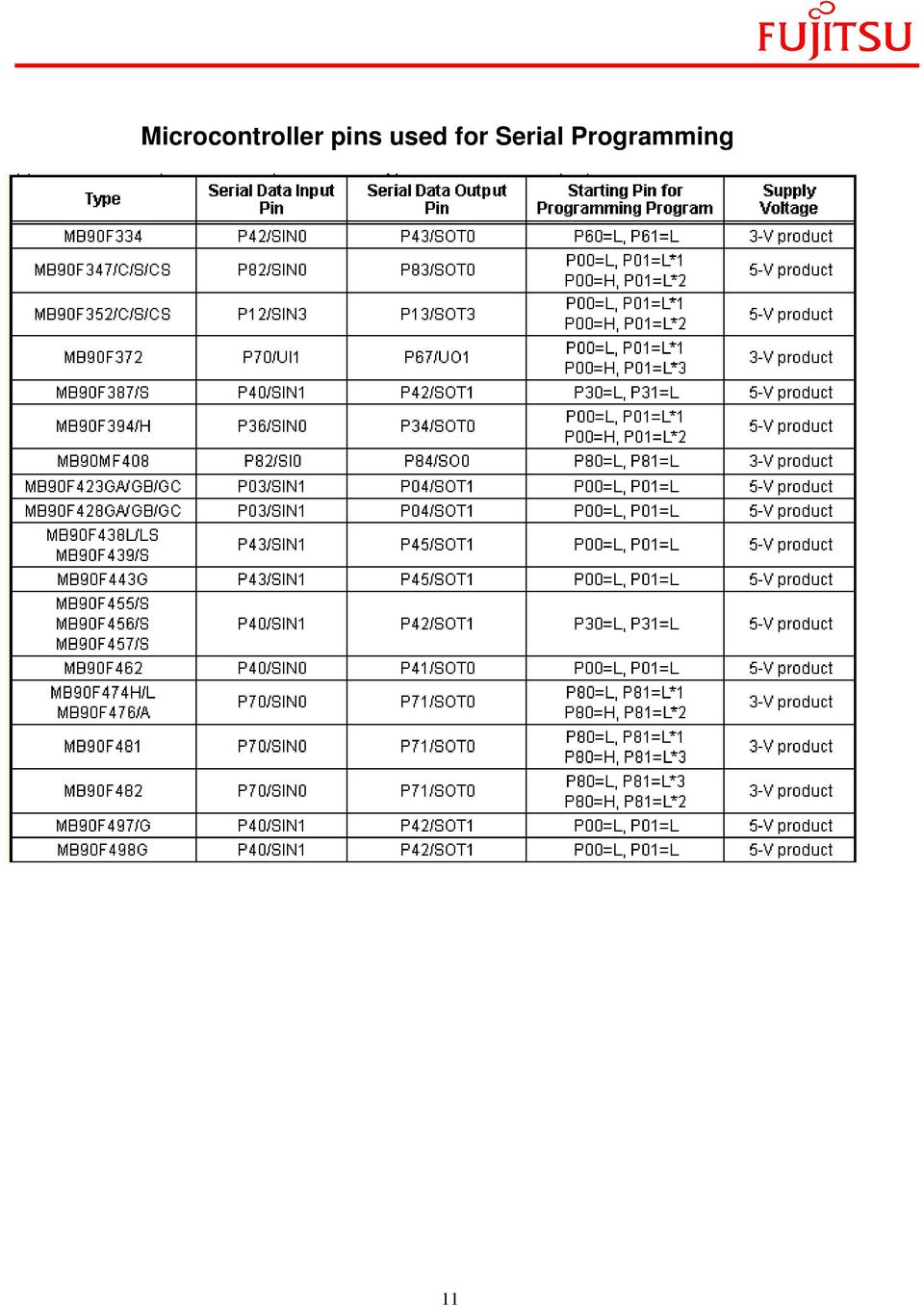
12 Microcontroller pins used for Serial Programming 12

13 Appendix B MCU Pins used for Flash asynchronous Programming in FR Family 13

14 Type Microcontroller pins used for Serial Programming Serial Data Input pin Serial data output pin Starting pin for programming program MB91F109 SI0/PF0/TRG0 SO0/PF1/TRG1 P20, P21 MB91F133 PI0/SIN1 P11/SOT1 P20, P21 MB91F233 P00/SIN0 PO1/SOT0 P10, P11 MB91F264 P20/SIN0 P21/SOT0 P44, P45 MB91FV310/F312 SI0 SO0 P33, P34 MB91F353/F355 PH3/SI3 PH4/SO3 PN0, PN2 MB91F362/365/366/367/368/369 SIN0 SOT0 14

Fujitsu Microelectronics Europe Application Note MCU-AN-300104-E-V10 FR FAMILY 32-BIT MICROCONTROLLER MB91460 CLOCK SUPERVISOR APPLICATION NOTE
 Fujitsu Microelectronics Europe Application Note MCU-AN-300104-E-V10 FR FAMILY 32-BIT MICROCONTROLLER MB91460 CLOCK SUPERVISOR APPLICATION NOTE Revision History Revision History Date 2008-06-18 V1.0, First
Fujitsu Microelectronics Europe Application Note MCU-AN-300067-E-V11 FR FAMILY 32-BIT MICROCONTROLLER MB91460 CLOCK MONITOR APPLICATION NOTE
 Fujitsu Microelectronics Europe Application Note MCU-AN-300067-E-V11 FR FAMILY 32-BIT MICROCONTROLLER MB91460 CLOCK MONITOR APPLICATION NOTE Revision History Revision History Date Issue 2008-06-02 V1.0,
TTL to RS232 Adapter User Guide
 TTL to RS232 Adapter User Guide Revision D March 28, 2011 Document Part Number GC-800-313d Copyright and Trademark Copyright 2006-2011, Grid Connect, Inc. All rights reserved. No part of this manual may
Temperature & Humidity SMS Alert Controller
 Temperature & Humidity SMS Alert Controller Version 7 [Windows XP/Vista/7] GSMS THR / GSMS THP Revision 110507 [Version 2.2.14A] ~ 1 ~ SMS Alarm Messenger Version 7 [Windows XP/Vista/7] SMS Pro series
User Manual. AS-Interface Programmer
 AS-Interface Programmer Notice: RESTRICTIONS THE ZMD AS-INTERFACE PROGRAMMER HARDWARE AND ZMD AS-INTERFACE PROGRAMMER SOFTWARE IS DESIGNED FOR IC EVALUATION, LABORATORY SETUP AND MODULE DEVELOPMENT ONLY.
Programming Flash Microcontrollers through the Controller Area Network (CAN) Interface
 Interface") Programming Flash Microcontrollers through the Controller Area Network (CAN) Interface Application te Programming Flash Microcontrollers through the Controller Area Network (CAN) Interface Abstract This
Programming Flash Microcontrollers through the Controller Area Network (CAN) Interface Application te Programming Flash Microcontrollers through the Controller Area Network (CAN) Interface Abstract This
Scanner Wedge for Windows Software User Guide
 Scanner Wedge for Windows Software User Guide Contents INSTALLING THE SCANNER WEDGE SOFTWARE 2 ACTIVATING THE SCANNER CONNECTION 3 TRACING SCANNER OUTPUT 7 FORMATTING OUTPUT 9 SELECTING START-UP OPTIONS
M68EVB908QL4 Development Board for Motorola MC68HC908QL4
 M68EVB908QL4 Development Board for Motorola MC68HC908QL4! Axiom Manufacturing 2813 Industrial Lane Garland, TX 75041 Email: [email protected] Web: http://www.axman.com! CONTENTS CAUTIONARY NOTES...3 TERMINOLOGY...3
ENTERPRISE EDITION INSTALLER END USER LICENCE AGREEMENT THIS AGREEMENT CONSISTS OF THREE PARTS:
 ENTERPRISE EDITION INSTALLER END USER LICENCE AGREEMENT THIS AGREEMENT CONSISTS OF THREE PARTS: A. VNC SERVER ENTERPRISE EDITION END USER LICENCE AGREEMENT B. VNC VIEWER ENTERPRISE EDITION END USER LICENCE
R4/F4 Series Master Development System User's Guide
 R/F Series Master Development System User's Guide Table of Contents Introduction Ordering Information R/F Series Receiver Development Board Board Objects Initial Setup Troubleshooting The Prototyping
User Manual IC-485AI 2002-09-27
 User Manual IC-485AI Note: This equipment has been tested and found to comply ith the limits for a Class A digital device pursuant to Part 15 of the FCC Rules. These limits are designed to provide reasonable
EasyPIC4 User s Manual
 SOFTWARE AND HARDWARE SOLUTIONS FOR THE EMBEDDED WORLD MikroElektronika - Books - Compilers User s Manual PIC MICROCHIP DEVELOPMENT BOARD 3in1 mikro IN-CIRCUIT DEBUGGER USB 2.0 IN-CIRCUIT PROGRAMMER With
SMARTCARD XPRO. Preface. SMART ARM-based Microcontrollers USER GUIDE
 SMART ARM-based Microcontrollers SMARTCARD XPRO USER GUIDE Preface Atmel SMARTCARD Xplained Pro is an extension board to the Atmel Xplained Pro evaluation platform. Atmel SMARTCARD Xplained Pro is designed
AGS. Owner's Manual. Xantrex Automatic Generator Start Control System
 AGS Owner's Manual Xantrex Automatic Generator Start Control System TABLE OF CONTENTS INTRODUCTION...3 Main Features...3 Safety Summary...3 THINGS YOU SHOULD KNOW...4 THEORY OF OPERATION...5 System...5
FR FAMILY MB91460 SPI - DAISY CHAIN COMMUNICATION 32-BIT MICROCONTROLLER APPLICATION NOTE. Fujitsu Microelectronics Europe Application Note
 Fujitsu Microelectronics Europe Application Note MCU-AN-300101-E-V10 FR FAMILY 32-BIT MICROCONTROLLER MB91460 SPI - DAISY CHAIN COMMUNICATION APPLICATION NOTE Revision History Revision History Date 2008-07-13
USB / Data-Acquisition Module NOW LEAD-FREE
 USB / Data-Acquisition Module NOW LEAD-FREE DLP-TEMP-G Features: Digital I/Os, Analog Inputs (0- Volts) or any combination USB. and.0 Compatible Interface th Generation Silicon from FTDI Supports Up To
PL-1, Pocket Logger 11-0135B
 PL-1, Pocket Logger 1 PL-1... 2 2 Wiring... 3 2.1.1 Single Innovate Device Relay Wiring Instructions... 3 3 Mounting... 4 4 Connecting the PL-1 to the MTS serial chain... 4 5 Recording... 5 6 LogWorks...
Teleservice via RS232 interface XC100/XC200
 User Manual 10/10 MN0500005Z-EN replaces 07/04 AWB74-1490GB Teleservice via RS interface XC100/XC00 All brand and product names are trademarks or registered trademarks of the owner concerned. Emergency
M CORE 14-PIN ENHANCED BACKGROUND DEBUG INTERFACE (14EBDI) USER S MANUAL
 USER S MANUAL") MMC14EBDIUM/D February 2000 M CORE 14-PIN ENHANCED BACKGROUND DEBUG INTERFACE (14EBDI) USER S MANUAL While every effort has been made to ensure the accuracy of all information in this document, Motorola
MMC14EBDIUM/D February 2000 M CORE 14-PIN ENHANCED BACKGROUND DEBUG INTERFACE (14EBDI) USER S MANUAL While every effort has been made to ensure the accuracy of all information in this document, Motorola
PCAN-MicroMod Universal I/O Module with CAN Interface. User Manual. Document version 2.1.0 (2014-01-16)
") PCAN-MicroMod Universal I/O Module with CAN Interface User Manual Document version 2.1.0 (2014-01-16) Products taken into account Product Name Part number Model PCAN-MicroMod IPEH-002080 with firmware
PCAN-MicroMod Universal I/O Module with CAN Interface User Manual Document version 2.1.0 (2014-01-16) Products taken into account Product Name Part number Model PCAN-MicroMod IPEH-002080 with firmware
APPLICATION NOTE. AT07175: SAM-BA Bootloader for SAM D21. Atmel SAM D21. Introduction. Features
 APPLICATION NOTE AT07175: SAM-BA Bootloader for SAM D21 Atmel SAM D21 Introduction Atmel SAM Boot Assistant (Atmel SAM-BA ) allows In-System Programming (ISP) from USB or UART host without any external
FN:PCMCSET-M1.DOC. PCMCSET SOFTWARE for ATS Master Clocks System Clocks and Displays
 FN:PCMCSET-M1.DOC PCMCSET SOFTWARE for ATS Master Clocks System Clocks and Displays ATS FREE SOFTWARE AGREEMENT Applied Technical Systems (ATS) grants you the right to use this software according to the
APPLICATION. Using the PB-100 to Make Calls and Announcements From a Database. Using the PB-100 for All-Call Dialing
 APPLICATION Note TELECOM SOLUTIONS FOR THE 21ST CENTURY Using the PB-100 for All-Call Dialing March 22, 2002 Features Compatible with Windows 95, 98, ME, NT 4.0, 2000 Male sub-d 9 pin cable provided 20
XPort Universal Demo Board User Guide
 XPort Universal Demo Board User Guide Part Number 900-563 Revision A September 2009 Copyright and Trademark Contacts 2009 Lantronix. All rights reserved. No part of the contents of this book may be transmitted
Bachmann PrintBoy SDK HTML Edition API Reference for CodeWarrior C/C++ Developers version 7.0
 Bachmann PrintBoy SDK HTML Edition API Reference for CodeWarrior C/C++ Developers version 7.0 Essential Printing and File Management Software for Palm OS and Pocket PC Handhelds Bachmann PrintBoy SDK copyright
Power Log PC Application Software
 Power Log PC Application Software Users Manual May 2007 Rev. 1, 5/08 2007-2008 Fluke Corporation. All rights reserved. Specifications are subject to change without notice. All product names are trademarks
Exeba -ATS. User Guide. Escan Technologies Corporation
 Escan Technologies Corporation Exeba -ATS User Guide Escan Technologies Corp. 12140 Severn Way Riverside, CA 92503 Phone (909) 270-0043 Fax (909) 270-0920 1 ESCAN TECHNOLOGIES CORPORATION Exeba -ATS User
DSO138 oscilloscope program upgrade method
 DSO138 oscilloscope program upgrade method Applicable models: 13801K, 13802K Program upgrade Principle The DSO138 is a SCM STM32F103C8 internal oscilloscope that is preinstalled with a flash bootloader,
RS-232 COMMUNICATIONS
 Technical Note D64 0815 RS-232 COMMUNICATIONS RS-232 is an Electronics Industries Association (EIA) standard designed to aid in connecting equipment together for serial communications. The standard specifies
The Programming Interface
 : In-System Programming Features Program any AVR MCU In-System Reprogram both data Flash and parameter EEPROM memories Eliminate sockets Simple -wire SPI programming interface Introduction In-System programming
WIZ-Embedded WebServer User s Manual (Ver. 1.0)
") [텍스트 입력] WIZ-Embedded WebServer User s Manual (Ver. 1.0) 2007 WIZnet Inc. All Rights Reserved. For more information, visit our website at www.wiznet.co.kr Document History Information Revision Data Description
[텍스트 입력] WIZ-Embedded WebServer User s Manual (Ver. 1.0) 2007 WIZnet Inc. All Rights Reserved. For more information, visit our website at www.wiznet.co.kr Document History Information Revision Data Description
VM-4 USB Desktop Audio Device Installation Guide
 VM-4 USB Desktop Audio Device Installation Guide THE POSSIBILITIES ARE ENDLESS. 9 Austin Drive, Marlborough, CT 06447 (860) 295-8100 www.essentialtel.com [email protected] Table of Contents Introduction...3
Powerware Relay-Serial Card User s Guide
 Powerware Relay-Serial Card User s Guide Special Symbols The following are examples of symbols used on the UPS and accessories to alert you to important information: This symbol indicates that you should
2-Port RS232/422/485 Combo Serial to USB2.0 Adapter (w/ Metal Case and Screw Lock Mechanism) Installation Guide
 Installation Guide") 2-Port RS232/422/485 Combo Serial to USB2.0 Adapter (w/ Metal Case and Screw Lock Mechanism) Installation Guide 1. Introduction Thank you for purchasing this 2-Port RS232/422/485 Combo Serial to USB Adapter.
2-Port RS232/422/485 Combo Serial to USB2.0 Adapter (w/ Metal Case and Screw Lock Mechanism) Installation Guide 1. Introduction Thank you for purchasing this 2-Port RS232/422/485 Combo Serial to USB Adapter.
VM-8 USB Desktop Audio Device Installation Guide
 VM-8 USB Desktop Audio Device Installation Guide THE POSSIBILITIES ARE ENDLESS. 9 Austin Drive, Marlborough, CT 06447 (860) 295-8100 www.essentialtel.com [email protected] Table of Contents Introduction...3
BACnet Automation Interface Module (Network Version)
") Sense +V Tx Rx LAN LINK Over ARCNET KBaud BACnet Rx BACnet Tx Archive Valid Port S Tx Port S Rx Low Battery Network- Enhanced Access Default MSTP PTP = Download Required on Rnet and Port S IP Address IP
Sense +V Tx Rx LAN LINK Over ARCNET KBaud BACnet Rx BACnet Tx Archive Valid Port S Tx Port S Rx Low Battery Network- Enhanced Access Default MSTP PTP = Download Required on Rnet and Port S IP Address IP
DK40 Datasheet & Hardware manual Version 2
 DK40 Datasheet & Hardware manual Version 2 IPC@CHIP DK40 Evaluation module Beck IPC GmbH http://www.bcl.de page 1 of 11 Table of contents Table of contents... 2 Basic description... 3 Characteristics...
The Analyst RS422/RS232 Tester. With. VTR, Monitor, and Data Logging Option (LOG2) User Manual
 User Manual") 12843 Foothill Blvd., Suite D Sylmar, CA 91342 818 898 3380 voice 818 898 3360 fax www.dnfcontrolscom The Analyst RS422/RS232 Tester With VTR, Monitor, and Data Logging Option (LOG2) User Manual Manual
12843 Foothill Blvd., Suite D Sylmar, CA 91342 818 898 3380 voice 818 898 3360 fax www.dnfcontrolscom The Analyst RS422/RS232 Tester With VTR, Monitor, and Data Logging Option (LOG2) User Manual Manual
PC Utility User s Manual
 SAM4s ER-265 Series PC Utility User s Manual Version 1.0 All specifications are subject to change without notice. 2006, CRS, Inc. CRS, Inc. Limited Warranty and Disclaimers of Warranty This manual has
CITRIX SYSTEMS, INC. SOFTWARE LICENSE AGREEMENT
 CITRIX SYSTEMS, INC. SOFTWARE LICENSE AGREEMENT PLEASE READ THIS SOFTWARE LICENSE AGREEMENT CAREFULLY BEFORE DOWNLOADING, INSTALLING OR USING CITRIX OR CITRIX-SUPPLIED SOFTWARE. BY DOWNLOADING OR INSTALLING
Crow Limited Warranty. Print Version 017
 Crow Limited Warranty (Crow) warrants this product to be free from defects in materials and workmanship under normal use and service for a period of one year from the last day of the week and year whose
Advanced Data Capture and Control Systems
 Advanced Data Capture and Control Systems Tronisoft Limited Email: [email protected] Web: www.tronisoft.com RS232 To 3.3V TTL User Guide RS232 to 3.3V TTL Signal Converter Modules P/N: 9651 Document
EvB 5.1 v5 User s Guide
 EvB 5.1 v5 User s Guide Page 1 Contents Introduction... 4 The EvB 5.1 v5 kit... 5 Power supply...6 Programmer s connector...7 USB Port... 8 RS485 Port...9 LED's...10 Pushbuttons... 11 Potentiometers and
USB to RS-422/485 Serial Adapter
 USB to RS-422/485 Serial Adapter User Manual Ver. 2.00 All brand names and trademarks are properties of their respective owners. Contents: Chapter 1: Introduction... 3 1.1 Product Introduction... 3 1.2
32-bit AVR UC3 Microcontrollers. 32-bit AtmelAVR Application Note. AVR32769: How to Compile the standalone AVR32 Software Framework in AVR32 Studio V2
 AVR32769: How to Compile the standalone AVR32 Software Framework in AVR32 Studio V2 1. Introduction The purpose of this application note is to show how to compile any of the application and driver examples
TOOLS for CC121 Installation Guide
 TOOLS for CC121 Installation Guide ATTENTION SOFTWARE LICENSE AGREEMENT PLEASE READ THIS SOFTWARE LICENSE AGREEMENT ( AGREEMENT ) CAREFULLY BEFORE USING THIS SOFTWARE. YOU ARE ONLY PERMITTED TO USE THIS
Single channel data transceiver module WIZ2-434
 Single channel data transceiver module WIZ2-434 Available models: WIZ2-434-RS: data input by RS232 (±12V) logic, 9-15V supply WIZ2-434-RSB: same as above, but in a plastic shell. The WIZ2-434-x modules
Develop a Dallas 1-Wire Master Using the Z8F1680 Series of MCUs
 Develop a Dallas 1-Wire Master Using the Z8F1680 Series of MCUs AN033101-0412 Abstract This describes how to interface the Dallas 1-Wire bus with Zilog s Z8F1680 Series of MCUs as master devices. The Z8F0880,
ELAN DIGITAL SYSTEMS LTD. SL232 PC- CARD USER S GUIDE
 ELAN DIGITAL SYSTEMS LTD. LITTLE PARK FARM ROAD, SEGENSWORTH WEST, FAREHAM, HANTS. PO15 5SJ. TEL: (44) (0)1489 579799 FAX: (44) (0)1489 577516 e-mail: [email protected] website: http://www.pccard.co.uk
Using the RS232 serial evaluation boards on a USB port
 Document information Info Content Keywords Serial evaluation Board, PN512,PN532, MFRC663, MFRC522, MFRC523, MFRC52x, MFRD522, MFRD523, MFRD52x MIFARE Contactless Smart Card Reader Reference Design, MIFARE
USER GUIDE EDBG. Description
 USER GUIDE EDBG Description The Atmel Embedded Debugger (EDBG) is an onboard debugger for integration into development kits with Atmel MCUs. In addition to programming and debugging support through Atmel
PC Base Adapter Daughter Card UART GPIO. Figure 1. ToolStick Development Platform Block Diagram
 TOOLSTICK VIRTUAL TOOLS USER S GUIDE RELEVANT DEVICES 1. Introduction The ToolStick development platform consists of a ToolStick Base Adapter and a ToolStick Daughter card. The ToolStick Virtual Tools
P O W E R S U P P L Y M A N U A L
 POWER SUPPLY MANUAL Congratulations on the purchase of your new Corsair power supply. This User Agreement (the Agreement ) is a legal agreement between you ( You ), and Corsair Memory, Inc. ( Corsair ).
CP2110-EK CP2110 EVALUATION KIT USER S GUIDE. 1. Kit Contents. 2. Relevant Documentation. 3. Software Setup
 CP2110 EVALUATION KIT USER S GUIDE 1. Kit Contents The CP2110 Evaluation Kit contains the following items: CP2110 Evaluation Board RS232 Serial Cable USB Cable DVD Quick Start Guide 2. Relevant Documentation
END USER LICENSE AGREEMENT FOR SLICKEDIT(R) CORE SOFTWARE IMPORTANT
 CORE SOFTWARE IMPORTANT") END USER LICENSE AGREEMENT FOR SLICKEDIT(R) CORE SOFTWARE IMPORTANT THIS IS A LEGAL AGREEMENT BETWEEN YOU ("You" or "Your") AND SLICKEDIT INC. ("SlickEdit"). SLICKEDIT IS WILLING TO (1) LICENSE THE SLICKEDIT
END USER LICENSE AGREEMENT FOR SLICKEDIT(R) CORE SOFTWARE IMPORTANT THIS IS A LEGAL AGREEMENT BETWEEN YOU ("You" or "Your") AND SLICKEDIT INC. ("SlickEdit"). SLICKEDIT IS WILLING TO (1) LICENSE THE SLICKEDIT
CryptoAuth Xplained Pro
 CryptoAuth Xplained Pro CryptoAuthentication Xplained Pro Extension Board HARDWARE USER GUIDE Atmel CryptoAuth Xplained Pro Extension Board Introduction The Atmel CryptoAuth Xplained Pro (CAXPro) Evaluation
Professional USB to Serial Adapter Hub with COM Retention
 Professional USB to Serial Adapter Hub with COM Retention ICUSB2321X ICUSB2322X ICUSB2324X *actual product may vary from photos *actual product may vary from photos DE: Bedienungsanleitung - de.startech.com
DMX USB PRO. User Manual. www.enttec.com
 DMX USB PRO User Manual www.enttec.com Firmware V1.43 February 2007 Package Contents Your DMX USB PRO package should contain these items: DMX USB PRO (Part No. 70304) Driver for Windows software on the
OBD2 PCM Programmer Quick Start Guide
 OBD2 PCM Programmer Quick Start Guide Table of Contents Introduction... 1 Minimum PC Requirements... 1 Program Installation... 1 Program Registration... 2 Program Setup... 3 Reading the PCM... 3 Programming
Block 3 Size 0 KB 0 KB 16KB 32KB. Start Address N/A N/A F4000H F0000H. Start Address FA000H F8000H F8000H F8000H. Block 2 Size 8KB 16KB 16KB 16KB
 APPLICATION NOTE M16C/26 1.0 Abstract The following article describes using a synchronous serial port and the FoUSB (Flash-over-USB ) Programmer application to program the user flash memory of the M16C/26
EIBWeiche Serial/USB
 User manual EIBWeiche Serial/USB The fast local buscoupler for the EIB Order codes: EIBWeiche Visualization serial: E001-B902101 EIBWeiche Visualization USB: E001-B902102 EIBWeiche Visualisierung USB REG:
BitBlaster Serial Download Cable
 BitBlaster Serial Download Cable February 2002, ver. 4.3 Data Sheet Features Allows PC and UNIX workstation users to perform the following functions: Program MAX 9000, MAX 7000S, MAX 7000A, and MAX 3000A
Bluetooth HC-06 with serial port module Easy guide
 1 Bluetooth HC-06 with serial port module Easy guide This manual consists of 3 parts: PART 1. Overview of Bluetooth HC-06 module with serial port. PART 2. Installing Bluetooth HC-06 module with Bolt 18F2550
MARTECH SPI Tools. MARTECH SPI Tools User Manual v1.0. User Manual
 MARTECH SPI Tools v1.0 Contents 1. Basic informations about the product...3 1.1 Memory types supported by SPI Tool...3 2. Main features and application possibilities...4 2.1 Technical Support activation...4
Manual Serial PCI Cards
 Manual Serial PCI Cards W&T Models 13011, 13410 13411, 13610 13611, 13812 Version 1.4 Subject to error and alteration 37 01/2005 by Wiesemann & Theis GmbH Subject to errors and changes: Since we can make
Technical Manual. For use with Caller ID signaling types: Belcore 202, British Telecom, & ETSI
 Technical Manual For use with Caller ID signaling types: Belcore 202, British Telecom, & ETSI Caller ID.com WHOZZ CALLING? POS 2 Caller ID Monitoring Unit Technical Manual For use with Caller ID signaling
How To Use An Atmel Atmel Avr32848 Demo For Android (32Bit) With A Microcontroller (32B) And An Android Accessory (32D) On A Microcontroller (32Gb) On An Android Phone Or
 With A Microcontroller (32B) And An Android Accessory (32D) On A Microcontroller (32Gb) On An Android Phone Or") APPLICATION NOTE Atmel AVR32848: Android Accessory Demo 32-bit Atmel Microcontrollers Features Control an accessory from an Android device Send data to and from an Android device to an accessory Supported
APPLICATION NOTE Atmel AVR32848: Android Accessory Demo 32-bit Atmel Microcontrollers Features Control an accessory from an Android device Send data to and from an Android device to an accessory Supported
COM Port Stress Test
 COM Port Stress Test COM Port Stress Test All rights reserved. No parts of this work may be reproduced in any form or by any means - graphic, electronic, or mechanical, including photocopying, recording,
AVR1922: Xplain Board Controller Firmware. 8-bit Microcontrollers. Application Note. Features. 1 Introduction
 AVR1922: Xplain Board Controller Firmware Features USB interface - Mass-storage to on-board DataFlash memory Atmel AVR XMEGA TM reset control 1 Introduction The Xplain board controller, an AT90USB1287,
BroadBand PowerShield. User Manual
 BroadBand PowerShield User Manual 990-0375G 12/2006 Chapter 1 General Information The PowerShield provides a power source for broadband telephony and other DC applications. Safety This Safety Guide contains
RS-232 to TTL Converter Cables SuperDroid Robots 2013 www.superdroidrobots.com
 Description: Designed for easy conversion of a RS-232 signals from a computer to TTL signals in order to interface a computer to a microcontroller or similar electronic devices Features: 72-inch in length
CHAPTER 11: Flip Flops
 CHAPTER 11: Flip Flops In this chapter, you will be building the part of the circuit that controls the command sequencing. The required circuit must operate the counter and the memory chip. When the teach
TERMS AND CONDITIONS 1 CONTRACT INFORMATION
 SUMMARY These terms and conditions govern your purchase of SocketCare for the Covered Products and for the Contract Term as defined herein. SocketCare is a service program that provides for the repair
MDM Zinc 3.0 End User License Agreement (EULA)
") MDM Zinc 3.0 End User License Agreement (EULA) THIS AGREEMENT (or "EULA") IS A LEGAL AGREEMENT BETWEEN THE PERSON, COMPANY, OR ORGANIZATION THAT HAS LICENSED THIS SOFTWARE ("YOU" OR "CUSTOMER") AND MULTIDMEDIA
MDM Zinc 3.0 End User License Agreement (EULA) THIS AGREEMENT (or "EULA") IS A LEGAL AGREEMENT BETWEEN THE PERSON, COMPANY, OR ORGANIZATION THAT HAS LICENSED THIS SOFTWARE ("YOU" OR "CUSTOMER") AND MULTIDMEDIA
GPS 35 USB. installation and quick start guide
 GPS 35 USB installation and quick start guide 2001 GARMIN Corporation GARMIN International, Inc. 1200 E 151 st Street, Olathe, Kansas 66062 U.S.A. Tel. 913/397.8200 Fax. 913/397.8282 GARMIN (Europe) Ltd.
Figure 1. 8-Bit USB Debug Adapter
 8-BIT USB DEBUG ADAPTER USER S GUIDE 1. Introduction The 8-bit USB Debug Adapter (UDA) provides the interface between the PC s USB port and the Silicon Labs 8-bit target device s in-system debug/programming
How To Develop A Toolstick
 TOOLSTICK BASE ADAPTER USER S GUIDE 1. Handling Recommendations To enable development, the ToolStick Base Adapter and daughter cards are distributed without any protective plastics. To prevent damage to
Switch board datasheet EB007-00-1
 Switch board datasheet EB007-00-1 Contents 1. About this document... 2 2. General information... 3 3. Board layout... 4 4. Testing this product... 5 5. Circuit description... 6 Appendix 1 Circuit diagram
RDF1. RF Receiver Decoder. Features. Applications. Description. Ordering Information. Part Number Description Packages available
 RDF1 RF Receiver Decoder Features Complete FM Receiver and Decoder. Small Form Factor Range up to 200 Metres* Easy Learn Transmitter Feature. Learns 40 transmitter Switches 4 Digital and 1 Serial Data
SB-1000 Link-All-3.0 USB Radio interface Operating Manual CG Antenna Co. Ltd.
 CG Antenna SB-1000 Link-All-3.0 USB Radio interface Operating Manual CG Antenna Co. Ltd. Shanghai, China - 1 - http://www.cgantenna.com FEATURES Connect your computer with USB port. No need serial or parallel
Alarm Clock USER GUIDE
 Alarm Clock USER GUIDE Jazwares, Inc. 2012 CONTENTS Please read the instructions along with the Alarm Clock carefully before you use it, so that you can operate it conveniently. WELCOME & Warnings Page
In-System Programmer USER MANUAL RN-ISP-UM RN-WIFLYCR-UM-.01. www.rovingnetworks.com 1
 RN-WIFLYCR-UM-.01 RN-ISP-UM In-System Programmer 2012 Roving Networks. All rights reserved. Version 1.1 1/19/2012 USER MANUAL www.rovingnetworks.com 1 OVERVIEW You use Roving Networks In-System-Programmer
Welcome to Maritime Information Systems Merchant Vessel Database (MVDB)
") Welcome to Maritime Information Systems Merchant Vessel Database (MVDB) MVDB for Windows 95* and Windows 98 offers a complete U.S. Vessel Documentation database capable of searching, saving, exporting,
Welcome to Maritime Information Systems Merchant Vessel Database (MVDB) MVDB for Windows 95* and Windows 98 offers a complete U.S. Vessel Documentation database capable of searching, saving, exporting,
MCB3101 (Class I) WiRobot Serial Bluetooth Wireless Module User Manual
 WiRobot Serial Bluetooth Wireless Module User Manual") MCB3101 (Class I) WiRobot Serial Bluetooth Wireless Module User Manual Version: 1.0.1 Dec. 2005 Table of Contents I. Introduction 2 II. Operations 2 II.1. Theory of Operation 2 II.2. Configuration (PC-PC
MCB3101 (Class I) WiRobot Serial Bluetooth Wireless Module User Manual Version: 1.0.1 Dec. 2005 Table of Contents I. Introduction 2 II. Operations 2 II.1. Theory of Operation 2 II.2. Configuration (PC-PC
AC 800M. EtherNet/IP DeviceNet Linking Device LD 800DN. Power and productivity for a better world TM SP1134
 AC 800M EtherNet/IP DeviceNet Linking Device LD 800DN SP1134 Power and productivity for a better world TM AC 800M EtherNet/IP DeviceNet Linking Device LD 800DN NOTICE This document contains information
Microstep Driver Manual Version 6/13/2006
 Microstep Driver Manual Version 6/13/2006 Embedded Acquisition Systems 2517 Cobden Street Sterling Heights, MI 48310 http://www.embeddedtronics.com email [email protected] copyright 2003-2004 EAS
Programming the On-Chip Flash on a phycore-xc161 phycore-xc167
 Application Note Programming the On-Chip Flash on a phycore-xc161 phycore-xc167 Application Note Edition July 2003 LAN-020e_1 Application Note Preface...1 1 Installing Infineon MemTool...2 2 Preparing
General Terms and Conditions for Online Sales of TomTom Inc ( TomTom )
") General Terms and Conditions for Online Sales of TomTom Inc ( TomTom ) 1) Scope a) These Terms and Conditions shall apply to all purchase orders submitted or to be submitted by you for any item, service
General Terms and Conditions for Online Sales of TomTom Inc ( TomTom ) 1) Scope a) These Terms and Conditions shall apply to all purchase orders submitted or to be submitted by you for any item, service
Designing VM2 Application Boards
 Designing VM2 Application Boards This document lists some things to consider when designing a custom application board for the VM2 embedded controller. It is intended to complement the VM2 Datasheet. A
1.1 Connection. 1.1.1 Direct COM port connection. 1. Half duplex RS232 spy cable without handshaking
 POS function Marchen POS-DVR surveillance system is a professional surveillance integrated with POS system. By bringing video and POS transaction data together, the POS-DVR surveillance system provides
Quick Installation Guide TK-209K TK-409K
 Quick Installation Guide TK-209K TK-409K Table of of Contents Contents English... 1. Before You Start... 2. How to Connect... 3. Operation... 1 1 2 4 Troubleshooting... 5 Version 09.07.2006 1. Before You
VPCCCare. Virtual PC Center Service Warranty Program
 VPCCCare Virtual PC Center Service Warranty Program Proprietary Notice and Liability Disclaimer The information disclosed in this document, including all designs and related materials, is the valuable
MACTek Corporation. USB HART Interface. Users Manual
 MACTek Corporation USB HART Interface DM01003100AA February, 2003 LIMITED WARRANTY VIATOR Interface for HART MACTek Corporation warrants this Interface and all of its component against defects in materials
Date Rev. Details Author
 Jtech engineering ltd J - Te c h E n g i n e e ring, L t d. 11080 Bond Boulevard Delta BC V4E 1M7 Canada Tel: 604 543 6272 Fax: 604 543 6476 http://www.jtecheng.com AUTODIALER USER S MANUAL REVISION HISTORY
8-bit. Application Note. Microcontrollers. AVR282: USB Firmware Upgrade for AT90USB
 AVR282: USB Firmware Upgrade for AT90USB Features Supported by Atmel FLIP program on all Microsoft O/S from Windows 98SE and later FLIP 3.2.1 or greater supports Linux Default on chip USB bootloader In-System
AVR151: Setup and Use of the SPI. Introduction. Features. Atmel AVR 8-bit Microcontroller APPLICATION NOTE
 Atmel AVR 8-bit Microcontroller AVR151: Setup and Use of the SPI APPLICATION NOTE Introduction This application note describes how to set up and use the on-chip Serial Peripheral Interface (SPI) of the
Ash Capture Control User Guide
 Ash Capture Control User Guide Revision 1.4 Table of Contents Software Installation... 3 Hardware Installation... 6 System Block Diagram... 7 Using Ash Capture Control... 8 Launching the Application...