Electromagnetic Force Coupling in Electric Machines. Mark Solveson, Cheta Rathod, Mike Hebbes, Gunjan Verma, Tushar Sambharam ANSYS, Inc.
|
|
|
- Alicia Stone
- 6 years ago
- Views:
Transcription

1 Electromagnetic Force Coupling in Electric Machines Mark Solveson, Cheta Rathod, Mike Hebbes, Gunjan Verma, Tushar Sambharam ANSYS, Inc. 1

2 Introduction Low noise regulation Aimed at reduction in noise pollution Comfort Criteria Noise causes discomfort and fatigue Noise suppression demonstrates technological/marketing edge Component Failure Sensitivity of structure to acoustic resonances The above Applies to many Industry sectors: Transportation, Power, Environmental, Building services 2


3 Introduction Noise and vibration in electric machines come from many sources. ANSYS provides excellent capabilities for the design and analysis of electric machines: Electromagnetic performance Electric Drive performance Structural analysis Thermal analysis Acoustics analysis ANSYS field coupling technology allows mapping of electromagnetic forces for Mechanical analysis 3


4 Machine Types Different machines may have different considerations depending on their architecture or control strategies. Primary Forces are in plane (radial and tangential) Single and Three Phase Induction Machines. PM Synchronous Machines (Surface Mount, IPM). Switched reluctance machines Primary force are Axial Axial Flux Machines 4
![Noise Sources [1] Magnetic Mechanical Aerodynamic Electronic Radial Fluid Cooling Phenomena Switching Harmonics Slot Harmonics Self Auxiliaries Load Induced Magnetic Unbalance Stator Rotor Couplings](/docs-images/71/64276787/images/5-0.jpg "Modes of Vibration Bearings Balancing Static Eccentricity Foundation Audible Frequencies Dynamic Eccentricity Elliptical Rotor Surface Unbalanced Rotor 20 Hz 60 Hz 261.63 Hz 4.")
5 Noise Sources [1] Magnetic Mechanical Aerodynamic Electronic Radial Fluid Cooling Phenomena Switching Harmonics Slot Harmonics Self Auxiliaries Load Induced Magnetic Unbalance Stator Rotor Couplings Modes of Vibration Bearings Balancing Static Eccentricity Foundation Audible Frequencies Dynamic Eccentricity Elliptical Rotor Surface Unbalanced Rotor 20 Hz 60 Hz Hz 4.186kHz 5 khz 20 khz 5 [1] P. Vigayraghavan, R. Krishnan, Noise in Electric Machines: A Review, IEEE, 1998
6 ANSYS Machine Model 6


7 Electromagnetic Design and Analysis ANSYS Machine Design Methodology RMxprt: calculate rated performance for machine Maxwell: Calculate detailed magnetic FEA of machine in time domain Simplorer: Calculate detailed drive design with coupled cosimulation with either RMxprt or Maxwell. SINE1 SINE2 SINE3 TRIANG1 E1 IGBT1 D7 IGBT3 D9 IGBT5 D11 RphaseA RphaseB PhaseA_in PhaseA_out + V RphaseC PhaseB_in PhaseB_out VM1 PhaseC_in PhaseC_out E2 IGBT2 D8 IGBT4 D10 IGBT6 D12 MotionSetup1_in 0 MotionSetup1_out + V_ROTB1 7
 motor model created from RMxprt and Maxwell UDP (User Defined Primitive) for rotor Model V Model DModel1 SModel1 4")

8 V V V V V V TR TR TR TR Curve Info SINE1.VAL SINE2.VAL SINE3.VAL TRIANG1.VAL ANSOFT Machine Model in Maxwell Simplorer 2D IPM (Interior Permanent Magnet) motor model created from RMxprt and Maxwell UDP (User Defined Primitive) for rotor Model V Model DModel1 SModel1 4 pole, 1500 RPM, 220 Volt DC bus. Two Control Strategies used: 6 step inverter In Maxwell PWM current regulated Cosimulation Maxwell with Simplorer V LabelID=V32 110V LabelID=V33 D40 S_46 D34 D35 D41 S_47 D42 S_48 D36 D37 D43 S_49 D44 S_50 D38 D39 LabelID=VIA H*Kle ohm LPhaseA LA RA LabelID=VIB H*Kle ohm LPhaseB LB RB LabelID=VIC H*Kle ohm LPhaseC LC RC D45 S_51 LabelID=IVc1 LabelID=IVc2 LabelID=IVc3 LabelID=IVc4 LabelID=IVc5 LabelID=IVc6 100ohm 100ohm 100ohm 100ohm 100ohm 100ohm R20 R21 R22 R23 R24 R V 1V 1V 1V 1V 1V LabelID=V14 LabelID=V15 LabelID=V16 LabelID=V17 LabelID=V18 LabelID=V19 0 SINE1 SINE2 SINE3 TRIANG1 E1 IGBT1 D7 IGBT3 D9 IGBT5 D11 RphaseA RphaseB PhaseA_in PhaseA_out + PhaseB_in PhaseB_out E2 IGBT2 D8 VM1 V IGBT4 D10 IGBT6 D12 RphaseC PhaseC_in MotionSetup1_in PhaseC_out 0.88 MotionSetup1_out Sine Triangle Basic_Inverter Y1 V_ROTB Time [ms]

![I TR 12.50 10.00 10.00 5.00 FEA1.TORQUE 7.50 Y1 [A] 0.00-5.00 5.00-10.00 2.50-15.00 0.00 20.00 22.50 25.00 27.](/docs-images/71/64276787/images/9-1.jpg "50 30.00 32.50 35.00 37.50 40.00 Time [ms] -20.00 20.00 22.50 25.00 27.50 30.00 32.50 35.00 37.50 40.00 Time [ms] 9")
9 ANSOFT ANSOFT Machine Model in Maxwell Simplorer SAS IP, Inc Torque Basic_Inverter1 SAS IP, Inc Currents Basic_Inverter1 Curve Info FEA1.TORQUE TR Curve Info RphaseA.I TR RphaseB.I TR RphaseC.I TR FEA1.TORQUE 7.50 Y1 [A] Time [ms] Time [ms] 9

![[9] Force calculation at a point on the](/docs-images/71/64276787/images/10-1.jpg "stator.")


10 Force Calculations Force calculation using air gap flux density Maxwell Stress Tensor [9] Force calculation at a point on the stator. Force on a line in the airgap Force on a line co linear with the stator tooth This is common method in literature. Edge Force Density Default field quantity available in Maxwell Can be used for creating lumped force calculations on tooth tips Automatic Force mapping from Maxwell to ANSYS Mechanical. (2D 2D, 2D 3D, 3D 3D) 10
 ExprCache(ToothTipTangent_2) ExprCache(ToothTipTangent_3) ExprCache(ToothTipTangent_4) ExprCache(ToothTipTangent_5) ExprCache(ToothTipTangent_6)")
![-30.00 0.00 5.00 10.00 15.00 20.00 25.00 30.00 35.00 40.00 Time [ms] Radial Force on Tooth Tips 02_DC-6step_IPM ANSOFT -0.00-50.00 Force (Newtons) -100.00-150.00-200.](/docs-images/71/64276787/images/11-1.jpg "00 Curve Info ExprCache(ToothTipRadial_Full1) ExprCache(ToothTipRadial_2) ExprCache(ToothTipRadial_3) ExprCache(ToothTipRadial_4) ExprCache(ToothTipRadial_5) ExprCache(ToothTipRadial_6) -250.")
11 Edge Force Density in Maxwell Tangential Force on Tooth Tips 02_DC-6step_IPM ANSOFT Force (Newtons) Curve Info ExprCache(ToothTipTangent_Full1) ExprCache(ToothTipTangent_2) ExprCache(ToothTipTangent_3) ExprCache(ToothTipTangent_4) ExprCache(ToothTipTangent_5) ExprCache(ToothTipTangent_6) Time [ms] Radial Force on Tooth Tips 02_DC-6step_IPM ANSOFT Force (Newtons) Curve Info ExprCache(ToothTipRadial_Full1) ExprCache(ToothTipRadial_2) ExprCache(ToothTipRadial_3) ExprCache(ToothTipRadial_4) ExprCache(ToothTipRadial_5) ExprCache(ToothTipRadial_6) Time [ms] 11

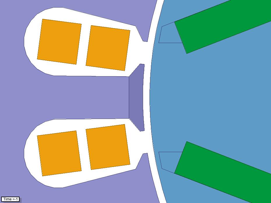

12 Eccentricity Model Left Side Tooth Right Side Tooth 12

13 Rotor missaligned 0%, 25%, 50% Parametric Study of Eccentricity Electromagetic Force Solved simultaneously on multi core computer Shown: Radial Force on Right Tooth Tip FFT of Radial Force 13


14 Edge Force Density, 50% Eccentricity 14
 -150.00 Force (N) -5.00-10.00-200.00-15.00-250.")
![00 Curve Info Radial Force Small Gap Radial Force Large Gap -300.00 20.00 22.50 25.00 27.50 30.00 Time [ms] 32.50 35.00 37.50 40.](/docs-images/71/64276787/images/15-1.jpg "00-20.00-25.00 Curve Info Tangential Force Small Gap Tangential Force Large Gap -30.00 20.00 22.50 25.00 27.50 30.00 Time [ms] 32.")
15 50% Eccentricity: Radial and Tangential Force on Right Side and Left Side Tooth 0.00 Radial Tooth Tip Forces ANSOFT Tangential Tooth Tip Forces ANSOFT Force (N) Force (N) Curve Info Radial Force Small Gap Radial Force Large Gap Time [ms] Curve Info Tangential Force Small Gap Tangential Force Large Gap Time [ms]
16 ANSYS Force Mapping 16


17 Two Approaches Direct Force Mapping Electromagnetic forces from Maxwell to Mechanical by linking systems in Workbench Maps 2D Edge Force, and 3D Surface force Transient Analysis for Stress prediction Lumped Force Mapping Tooth Tip objects created for mapping calculated lumped force using EdgeForceDensity in Maxwell. Apply these lumped forces manually or through APDL Macro Further harmonic and Noise Analysis 17


18 Approach 1 Direct Force Mapping Scenario: Study the effect of Rotor Eccentricity Case 1: 0% Eccentricity No misalignment Case 2: 50 % Eccentricity Eccentricity amount is set to 50% of gap width Creates unbalanced electromagnetic forces Peak Edge Force Density 1.5e6 N/m 2 18 Peak Edge Force Density 1.9e6 N/m 2
19 This image cannot currently be displayed. This image cannot currently be displayed. Directional Deformation Radial Max Deformation vs time Case 1 0% Eccentricity 19 Case 2 50 % Eccentricity
20 This image cannot currently be displayed. This image cannot currently be displayed. This image cannot currently be displayed. Von Misses Stress Max Stresses vs time Case 1 0% Eccentricity 20 Case 2 50 % Eccentricity

21 Results: Comparison Higher the amount of eccentricity, higher is the variation of electromagnetic forces, causing deformation of stator, vibration and noise Total Deformation Deformation higher for eccentric model Peak Stresses Stresses at time=12 ms Stator Stresses are non symmetric and higher for eccentric model where the air gap is minimum 21
22 Approach 2 Lumped Force Mapping Electromagnetic Forces Export forces Workbench Flow Chart for Noise Prediction ANSYS Maxwell ANSYS Mechanical ANSYS Acoustics Lumped Forces in Time Domain Real/Imaginary Forces In Frequency Domain Harmonic Response Extract Acoustic Pressures Perform FFT in Maxwell APDL in Workbench APDL in Workbench 22
23 ANSYS Harmonic Analysis 23


24 Modal Analysis: Get Resonant Frequencies Mode #1, 8502 Hz Mode #2, 8708 Hz Mode #3, 8708 Hz First four Natural Frequency and corresponding mode shapes 24 Mode #4, 9080 Hz
 To determine Acoustic response Boundary Conditions Input Forces Appling harmonic forces from Maxwell into ANSYS Mechanical 25")
25 Why Harmonic Analysis To make sure that a given design can withstand sinusoidal loads at different frequencies To detect resonant response and avoid it if necessary (e.g. using mechanical dampers, changing PWM frequency, etc.) To determine Acoustic response Boundary Conditions Input Forces Appling harmonic forces from Maxwell into ANSYS Mechanical 25


 occurs at 8710")
26 Harmonic Response Bode plot Frequency response at a selected node location of the model. Helps determine that Max Amplitude (1.7mm) occurs at 8710 Hz on the selected vertex 26


27 Harmonic Response Contour plot Amplitude distribution of the displacements at a specific frequency, Deformation plot at 8710 Hz 27
28 ANSYS Acoustics 28
29 Acoustics Capabilities in ANSYS Acoustics is the study of the generation, propagation, absorption, and reflection of sound pressure waves in an acoustic medium. Acoustic problems can be identified as Vibro Acoustics: Sound generated structurally (ANSYS Mechanical) Aero Acoustics : Sound generated aerodynamically (ANSYS CFD) 29
30 Modeling Aero Acoustics (ANSYS CFD) Free Space Problem with no solid surfaces: sound generated from turbulence, jet noise Free Space Problem with solid surfaces: Fan noise, airframe noise, rotor noise, boundary layer noise, cavity noise Interior problem: Duct noise, mufflers, ducted fan noise Sound pressure fluctuations 30
. Applied loads are obtained from Maxwell.")
31 Vibro Acoustics (ANSYS Mechanical) Computing the acoustic field radiated by a vibrating structure Structure modeled in ANSYS Mechanical where vibration patterns are calculated (Modal, Harmonic Analysis). Applied loads are obtained from Maxwell. Vibration patterns used as boundary conditions to compute acoustic field radiated by structure (ANSYS MAPDL, ANSYS Acoustic Structures) 31

32 This image cannot currently be displayed. This image cannot currently be displayed. Acoustic Analysis Pressure Plot 32

33 Acoustic Analysis Pressure Plot 0.5 m Pres_1 Pres_2 Pres_3 Pressure vs Freq Pressure (Pa) 33 Freq(Hz)
34 Summary Investigated different noise sources for electric machines Demonstrated an integrated approach from Electromagnetics to Structural to Acoustics. Showed the effects of static eccentricity on stator tooth forces, deformation and stresses. Performed modal analysis to find the acoustic resonances Future Work: Investigation of different noise scenarios (machine types, drives) Include more mechanical details (windings, housing, etc) Expand harmonic analysis to include higher frequency content of forces Further investigation of Aero acoustics with ANSYS CFD 34
35 References [1] P. Vijayraghavan, R. Krishnan, Noise in electric machines: A Review, IEEE, 1998 [2] K. Shiohata, R. Kusama, S.Ohtsu, T.Iwatsubo, The Study on Electromagnetic Force Induced Vibration and Noise from a Normal and Eccentric Universal Motors, PIERS Proceedings, [3] S. Fink, S. Peters, Ansoft Noise Prediction for Electrical Motors, CADFEM/ANSYS Presentation, [4] Wei Wang, Quanfeng Li, Zhihuan Song, Shenbo Yu, Jian Chen, Renyuan Tang, Three Dimensional Field Calculation and Analysis of Electromagnetic Vibration and Noise for Disk Permanent Magnet Synchronous Machines, Shenyang University of Technology, China. [5] R. Belmans, D. Verdyck, W. Geysen, R. Findlay, Electro Mechanical Analysis of the Audible Noise of an Inverter Fed Squirrel Cage Induction Motor, IEEE, [6] M. Anwar, I. Husain, Design Perspectives of a Low Acoustic Noise Switched Reluctance Machine, IEEE, [7] S. Huang, M. Aydin, T.A. Lipo, Electronmagnetic Vibration and Noise Assessment for Surface Mounted PM Machines, IEEE, [8] Rakib Islam, Iqbal Hussain, Analytical Model for Predicting Noise and Vibration in Permanent Magnet Synchronous Motors, IEEE [9] Pragasen Pillay, William (Wei) Cai, An Investigation into Vibration in Switched Reluctance Motors, IEEE Transactions on Industry Applications, Vol. 35, NO. 3, May/June,
36 Thank You 36


37 ANSYS Acoustics Structure ANSYS Acoustics Structures computes noise radiated by vibrating structures. From Harmonic Vibrations to Noise Estimates. ANSYS Acoustics Structures integrates with your current simulation tools. 37
38 Title and Abstract Electromagnetic Force Coupling in Electric Machines Including Stress, Deformation, and Acoustic Analysis. Understanding the impact of electromagnetic forces on noise generation for electric machines can include many factors. This presentation will review these issues and illustrate electromagnetic forces, stress, deformation, and acoustic coupling in ANSYS Workbench. An example showing automatic mapping of magnetic time domain forces, and a comparison of stresses for different rotor eccentricities will be shown. 38
39 Presentation Outline (Goal 30 total Slides) 1. Introduction 2. Literature review what are the noise comonents for electric machines a. Noise Sources, examples b. Acoustic Definition, examples 3. EM Motor Methodology a. RMxprt to Maxwell, Simplorer b. Force calculations c. Eccentricity Model 4. Mechanical Analysis a. 2D (3D?) transient force mapping results b. Discussion of FFT approaches (by inspection or 3 rd party tools/scripts) c. 2D (3D?) harmonic Analysis 5. Acoustic analysis a. General capabilities (acoustic elements, Actran coupling? ) b. Results for stator lamination 39
40 40 Noise Sources Magnetic The interaction of magnetic fields and currents in the machine cause electromagnetic torque and thus rotation of the rotor. Evaluation of the radial and tangential forces on the tooth tips are important. This can be accomplished through evaluation of the air gap flux density, or using Force Density field calculations available within Maxwell. If one of the radial force frequencies coincides with the natural frequency of the machine, resonance occurs leading to acoustic noise. Mixed product of stator and rotor winding space harmonics. Slot Harmonics Rotor Eccentricity: improper rotor alignment causing unbalanced magnetic forces on the stator. Lamination vibration due to magnetorestrictive forces (worst when not stacked properly) Electronic Switching noise Inverter PWM frequencies can be in audible range. Current through the winding Lorentz forces
41 41 Noise Sources Mechanical Self resonance natural resonance frequencies Closed form equations FEA Load induced Coupling of machine to load, and mounting. Auxiliaries Bearing Vibration Brush commutators Chattering Intra lamination Function of Bolt force Involves 3D Mechanical transient vibration analysis Manufacturing asymmetries of the rotor and stator nonuniform air gap Stator winding which are not installed properly Aero Dynamics CFD


42 Machine Model in Maxwell VB script Fields Calculator to create Radial and Tangential Force Expressions from EdgeForceDensity VB script Calculates Radial and Tangential Force on Tooth Tips Allows only force on edge that neighbors non ferrous objects Half teeth force components added together Add to Expression Cache 42
43 Harmonic Analysis Overview A technique to determine the steady state response of a structure to sinusoidal (harmonic) loads of known frequency. Input: Harmonic loads (forces, pressures, and imposed displacements) of known magnitude and frequency. (Obtained from Maxwell) May be multiple loads all at the same frequency. Output: Harmonic displacements at each DOF, usually out of phase with the applied loads. Other derived quantities, such as stresses and strains. 43
44 ANSYS Acoustics Structural borne noise (one way Vibro Acoustics) ANSYS Acoustics Structures (FFT s ACTRAN Solver) Vibro Acoustics ANSYS Mechanical (APDL Solver) Aero Acoustics ANSYS CFD Nonlinear fluid structure interaction ANSYS CFD + ANSYS Mechanical 44
45 Aero Acoustics ANSYS CFD Approaches Direct calculation: Resolve the acoustic pressure fluctuations as part of the CFD solution Couple CFD with specialized acoustics codes, Boundary Element Methods (BEM), Hybrid zonal methods Acoustic waves are not tracked with CDF solution Calculate wave propagation using specialized codes (ACTRAN, SYSNOISE) 45


46 Aero Acoustic simulation of Automotive Front End Module cooling fans by using FLUENT s Acoustic module Courtesy of Hyundai MOBIS, Korea Geometry of Cooling Fans Computational domain 46 Pressure Contours Flow Pathlines through Sound pressure fluctuations calculated at the receiver position


47 Subwoofer Example (ANSYS CFD) (non linear fluid with structure) Fluid Structure Interaction Solution Transient Pressures 47

48 Acoustic Energy Source Acoustic Structural Example Coupled Target Object: Nested Cylindrical Cans Scattered Acoustic Radiation FEA Model quarter Symmetry Hemispherical Domain Animation of Acoustic Pressure (Pa) 48
Wireless Power Transfer System Design. Julius Saitz ANSYS
 Wireless Power Transfer System Design Julius Saitz ANSYS 1 WPT System 2 Wireless Power Transfer (WPT) Near-Field (Inductive coupling, resonant) Do not rely on propagating EM waves Operate at distances
HIGH SPEED PERMANENT MAGNET SYNCHRONOUS MOTOR / GENERATOR DESIGN FOR FLYWHEEL APPLICATIONS
 HIGH SPEED PERMANENT MAGNET SYNCHRONOUS MOTOR / GENERATOR DESIGN FOR FLYWHEEL APPLICATIONS Aleksandr Nagorny, Ph.D. National Research Council Outline Introduction Selection of the Rated Point The major
Enhancing the Design of Electric Machines through the Interaction of Software Tools. Markus Anders Electric machine sector manager CD-adpaco
 Enhancing the Design of Electric Machines through the Interaction of Software Tools Markus Anders Electric machine sector manager CD-adpaco Outline Part I: SPEED and STAR-CCM+ Enhancing the thermal design
1150 hp motor design, electromagnetic and thermal analysis
 115 hp motor design, electromagnetic and thermal analysis Qasim Al Akayshee 1, and David A Staton 2 1 Mawdsley s Ltd., The Perry Centre, Davey Close, Waterwells, Gloucester GL2 4AD phone: +44 1452 888311
Principles of Adjustable Frequency Drives
 What is an Adjustable Frequency Drive? An adjustable frequency drive is a system for controlling the speed of an AC motor by controlling the frequency of the power supplied to the motor. A basic adjustable
Vehicle Design Summit Electric Hub Motor (V2) Eric Conner Harvey Tang Matthew Peddie
 Eric Conner Harvey Tang Matthew Peddie") Vehicle Design Summit Electric Hub Motor (V2) Eric Conner Harvey Tang Matthew Peddie Motivation The AHPV from VDS 1.0 used an expensive, NGM electric hub motor, costing roughly $8000. (picture on right)
Vehicle Design Summit Electric Hub Motor (V2) Eric Conner Harvey Tang Matthew Peddie Motivation The AHPV from VDS 1.0 used an expensive, NGM electric hub motor, costing roughly $8000. (picture on right)
Finite Element Analysis for Acoustic Behavior of a Refrigeration Compressor
 Finite Element Analysis for Acoustic Behavior of a Refrigeration Compressor Swapan Kumar Nandi Tata Consultancy Services GEDC, 185 LR, Chennai 600086, India Abstract When structures in contact with a fluid
Reliable World Class Insights Your Silicon Valley Partner in Simulation ANSYS Sales, Consulting, Training & Support
 www.ozeninc.com info@ozeninc.com (408) 732 4665 1210 E Arques Ave St 207 Sunnyvale, CA 94085 Reliable World Class Insights Your Silicon Valley Partner in Simulation ANSYS Sales, Consulting, Training &
2. Permanent Magnet (De-) Magnetization 2.1 Methodology
 Magnetization 2.1 Methodology") Permanent Magnet (De-) Magnetization and Soft Iron Hysteresis Effects: A comparison of FE analysis techniques A.M. Michaelides, J. Simkin, P. Kirby and C.P. Riley Cobham Technical Services Vector Fields
Permanent Magnet (De-) Magnetization and Soft Iron Hysteresis Effects: A comparison of FE analysis techniques A.M. Michaelides, J. Simkin, P. Kirby and C.P. Riley Cobham Technical Services Vector Fields
FREQUENCY CONTROLLED AC MOTOR DRIVE
 FREQUENCY CONTROLLED AC MOTOR DRIVE 1.0 Features of Standard AC Motors The squirrel cage induction motor is the electrical motor motor type most widely used in industry. This leading position results mainly
Electrical Drive Modeling through a Multiphysics System Simulation Approach
 Application Brief Electrical Drive Modeling through a The electric drive system is a key application in power electronics. Optimizing such complex mechatronic system requires in-depth analysis, expertise
CONVENTIONALLY reduced order models are being
 Co-Simulation of an Electric Traction Drive Christoph Schulte and Joachim Böcker Abstract For the simulation of electrical drives, reducedorder models or simple look-up tables are often used in order to
SYNCHRONOUS MACHINES
 SYNCHRONOUS MACHINES The geometry of a synchronous machine is quite similar to that of the induction machine. The stator core and windings of a three-phase synchronous machine are practically identical
SLOT FRINGING EFFECT ON THE MAGNETIC CHARACTERISTICS OF ELECTRICAL MACHINES
 Journal of ELECTRICAL ENGINEERING, VOL. 60, NO. 1, 2009, 18 23 SLOT FRINGING EFFECT ON THE MAGNETIC CHARACTERISTICS OF ELECTRICAL MACHINES Mohammad B. B. Sharifian Mohammad R. Feyzi Meysam Farrokhifar
Specifying a Variable Frequency Drive s
 Specifying a Variable Frequency Drive s Put on by Bruce Reeves and Jeremy Gonzales Dykman Electrical Covering the Western US For all of your VFD and Soft Start and Motor Needs How To Specify a Variable
*ADVANCED ELECTRIC GENERATOR & CONTROL FOR HIGH SPEED MICRO/MINI TURBINE BASED POWER SYSTEMS
 *ADVANCED ELECTRIC GENERATOR & CONTROL FOR HIGH SPEED MICRO/MINI TURBINE BASED POWER SYSTEMS Jay Vaidya, President Electrodynamics Associates, Inc. 409 Eastbridge Drive, Oviedo, FL 32765 and Earl Gregory,
Rotating Machinery Diagnostics & Instrumentation Solutions for Maintenance That Matters www.mbesi.com
 13 Aberdeen Way Elgin, SC 29045 Cell (803) 427-0791 VFD Fundamentals & Troubleshooting 19-Feb-2010 By: Timothy S. Irwin, P.E. Sr. Engineer tsi@mbesi.com Rotating Machinery Diagnostics & Instrumentation
Design and Analysis of Switched Reluctance Motors
 Design and Analysis of Switched Reluctance Motors İbrahim ŞENGÖR, Abdullah POLAT, and Lale T. ERGENE Electrical and Electronic Faculty, İstanbul Technical University, 34469, Istanbul, TURKEY sengoribrahim@gmail.com,
Overview. also give you an idea of ANSYS capabilities. In this chapter, we will define Finite Element Analysis and. Topics covered: B.
 2. FEA and ANSYS FEA and ANSYS Overview In this chapter, we will define Finite Element Analysis and also give you an idea of ANSYS capabilities. Topics covered: A. What is FEA? B. About ANSYS FEA and ANSYS
www.integratedsoft.com Electromagnetic Sensor Design: Key Considerations when selecting CAE Software
 www.integratedsoft.com Electromagnetic Sensor Design: Key Considerations when selecting CAE Software Content Executive Summary... 3 Characteristics of Electromagnetic Sensor Systems... 3 Basic Selection
Analysis of Space Vector Pulse Width Modulation VSI Induction Motor on various conditions
 Analysis of Space Vector Pulse Width Modulation VSI Induction Motor on various conditions Padma Chaturvedi 1, Amarish Dubey 2 1 Department of Electrical Engineering, Maharana Pratap Engineering College,
Performance Comparison of Dual-Rotor Radial-Flux and Axial-Flux Permanent-Magnet BLDC Machines
 Performance Comparison of Dual-Rotor Radial-Flux and Axial-Flux Permanent-Magnet BLDC Machines Ronghai Qu, Member, IEEE Electronic & Photonic Systems Technologies General Electric Company Bldg EP, Rm 110-B,
WIND TURBINE TECHNOLOGY
 Module 2.2-2 WIND TURBINE TECHNOLOGY Electrical System Gerhard J. Gerdes Workshop on Renewable Energies November 14-25, 2005 Nadi, Republic of the Fiji Islands Contents Module 2.2 Types of generator systems
Harmonics and Noise in Photovoltaic (PV) Inverter and the Mitigation Strategies
 Inverter and the Mitigation Strategies") Soonwook Hong, Ph. D. Michael Zuercher Martinson Harmonics and Noise in Photovoltaic (PV) Inverter and the Mitigation Strategies 1. Introduction PV inverters use semiconductor devices to transform the
Soonwook Hong, Ph. D. Michael Zuercher Martinson Harmonics and Noise in Photovoltaic (PV) Inverter and the Mitigation Strategies 1. Introduction PV inverters use semiconductor devices to transform the
THIS paper reports some results of a research, which aims to investigate the
 FACTA UNIVERSITATIS (NIŠ) SER.: ELEC. ENERG. vol. 22, no. 2, August 2009, 227-234 Determination of Rotor Slot Number of an Induction Motor Using an External Search Coil Ozan Keysan and H. Bülent Ertan
Slots Geometry Influence on the Air gap Magnetic Field Distribution
 Slots Geometry Influence on the Air gap Magnetic Field Distribution BELLAL ZAGHDOUD, ABDALLAH SAADOUN Electrical Engineering Department University of Annaba, ALGERIA b_zaghdoud@yahoo.com, saadoun_a@yahoo.fr
Design and Simulation of Z-Source Inverter for Brushless DC Motor Drive
 Science Arena Publications Specialty Journal of Electronic and Computer Sciences Available online at www.sciarena.com 2015, Vol, 1 (1): 30-34 Design and Simulation of Z-Source Inverter for Brushless DC
COMPUTATIONAL FLUID DYNAMICS (CFD) ANALYSIS OF INTERMEDIATE PRESSURE STEAM TURBINE
 ANALYSIS OF INTERMEDIATE PRESSURE STEAM TURBINE") Research Paper ISSN 2278 0149 www.ijmerr.com Vol. 3, No. 4, October, 2014 2014 IJMERR. All Rights Reserved COMPUTATIONAL FLUID DYNAMICS (CFD) ANALYSIS OF INTERMEDIATE PRESSURE STEAM TURBINE Shivakumar
Research Paper ISSN 2278 0149 www.ijmerr.com Vol. 3, No. 4, October, 2014 2014 IJMERR. All Rights Reserved COMPUTATIONAL FLUID DYNAMICS (CFD) ANALYSIS OF INTERMEDIATE PRESSURE STEAM TURBINE Shivakumar
Motor-CAD Software for Thermal Analysis of Electrical Motors - Links to Electromagnetic and Drive Simulation Models
 Motor-CAD Software for Thermal Analysis of Electrical Motors - Links to Electromagnetic and Drive Simulation Models Dave Staton, Douglas Hawkins and Mircea Popescu Motor Design Ltd., Ellesmere, Shropshire,
Bericht über FEMAG 3D
 Bericht über FEMAG 3D Dr.-Ing. Bogdan Funieru Würzburg, 21 October 2008 Dr.-Ing. B. Funieru 1 Contents Motivation and Concept LUA Script Extrusion Control Periodic Boundary Condition FEMAG 2D 3D Results
Simulation and Analysis of PWM Inverter Fed Induction Motor Drive
 Simulation and Analysis of PWM Inverter Fed Induction Motor Drive C.S.Sharma, Tali Nagwani Abstract Sinusoidal Pulse Width Modulation variable speed drives are increasingly applied in many new industrial
CNC Machine Control Unit
 NC Hardware a NC Hardware CNC Machine Control Unit Servo Drive Control Hydraulic Servo Drive Hydraulic power supply unit Servo valve Servo amplifiers Hydraulic motor Hydraulic Servo Valve Hydraulic Servo
8 Speed control of Induction Machines
 8 Speed control of Induction Machines We have seen the speed torque characteristic of the machine. In the stable region of operation in the motoring mode, the curve is rather steep and goes from zero torque
DHANALAKSHMI COLLEGE OF ENGINEERING DEPARTMENT OF ELECTRICAL AND ELECTRONICS ENGINEERING EE2302 - ELECTRICAL MACHINES II UNIT-I SYNCHRONOUS GENERATOR
 1 DHANALAKSHMI COLLEGE OF ENGINEERING DEPARTMENT OF ELECTRICAL AND ELECTRONICS ENGINEERING Constructional details Types of rotors EE2302 - ELECTRICAL MACHINES II UNIT-I SYNCHRONOUS GENERATOR PART A 1.
CHAPTER 4 DESIGN OF INTEGRAL SLOT AND FRACTIONAL SLOT BRUSHLESS DC MOTOR
 47 CHAPTER 4 DESIGN OF INTEGRAL SLOT AND FRACTIONAL SLOT BRUSHLESS DC MOTOR 4.1 INTRODUCTION This chapter deals with the design of 24 slots 8 poles, 48 slots 16 poles and 60 slots 16 poles brushless dc
d di Flux (B) Current (H)
 Current (H)") Comparison of Inductance Calculation Techniques Tony Morcos Magnequench Technology Center Research Triangle Park, North Carolina 1 VCM Baseline: Geometry Axially-magnetized MQ3-F 42 NdFeB disk Br = 131kG
Comparison of Inductance Calculation Techniques Tony Morcos Magnequench Technology Center Research Triangle Park, North Carolina 1 VCM Baseline: Geometry Axially-magnetized MQ3-F 42 NdFeB disk Br = 131kG
Lab 14: 3-phase alternator.
 Lab 14: 3-phase alternator. Objective: to obtain the no-load saturation curve of the alternator; to determine the voltage regulation characteristic of the alternator with resistive, capacitive, and inductive
Design and Simulation of Soft Switched Converter Fed DC Servo Drive
 International Journal of Soft Computing and Engineering (IJSCE) ISSN: 2231-237, Volume-1, Issue-5, November 211 Design and Simulation of Soft Switched Converter Fed DC Servo Drive Bal Mukund Sharma, A.
PREDICTION OF MACHINE TOOL SPINDLE S DYNAMICS BASED ON A THERMO-MECHANICAL MODEL
 PREDICTION OF MACHINE TOOL SPINDLE S DYNAMICS BASED ON A THERMO-MECHANICAL MODEL P. Kolar, T. Holkup Research Center for Manufacturing Technology, Faculty of Mechanical Engineering, CTU in Prague, Czech
Modelling, Simulation and Performance Analysis of A Variable Frequency Drive in Speed Control Of Induction Motor
 International Journal of Engineering Inventions e-issn: 78-7461, p-issn: 319-6491 Volume 3, Issue 5 (December 013) PP: 36-41 Modelling, Simulation and Performance Analysis of A Variable Frequency Drive
Getting Started with ANSYS ANSYS Workbench Environment
 Getting Started with ANSYS ANSYS Workbench Environment Overview The purpose of this tutorial is to get you started with the ANSYS Workbench environment. We will use a simple, static analysis of a single
MODELLING AND SIMULATION OF SVPWM INVERTER FED PERMANENT MAGNET BRUSHLESS DC MOTOR DRIVE
 MODELLING AND SIMULATION OF SVPWM INVERTER FED PERMANENT MAGNET BRUSHLESS DC MOTOR DRIVE Devisree Sasi 1, Jisha Kuruvilla P Final Year M.Tech, Dept. of EEE, Mar Athanasius College of Engineering, Kothamangalam,
Motor Fundamentals. DC Motor
 Motor Fundamentals Before we can examine the function of a drive, we must understand the basic operation of the motor. It is used to convert the electrical energy, supplied by the controller, to mechanical
DC GENERATOR THEORY. LIST the three conditions necessary to induce a voltage into a conductor.
 DC Generators DC generators are widely used to produce a DC voltage. The amount of voltage produced depends on a variety of factors. EO 1.5 LIST the three conditions necessary to induce a voltage into
Development Of High Efficiency Brushless DC Motor With New Manufacturing Method Of Stator For Compressors
 Purdue University Purdue e-pubs International Compressor Engineering Conference School of Mechanical Engineering 2002 Development Of High Efficiency Brushless DC Motor With New Manufacturing Method Of
How to Turn an AC Induction Motor Into a DC Motor (A Matter of Perspective) Steve Bowling Application Segments Engineer Microchip Technology, Inc.
 Steve Bowling Application Segments Engineer Microchip Technology, Inc.") 1 How to Turn an AC Induction Motor Into a DC Motor (A Matter of Perspective) Steve Bowling Application Segments Engineer Microchip Technology, Inc. The territory of high-performance motor control has
1 How to Turn an AC Induction Motor Into a DC Motor (A Matter of Perspective) Steve Bowling Application Segments Engineer Microchip Technology, Inc. The territory of high-performance motor control has
Dually Fed Permanent Magnet Synchronous Generator Condition Monitoring Using Stator Current
 Summary Dually Fed Permanent Magnet Synchronous Generator Condition Monitoring Using Stator Current Joachim Härsjö, Massimo Bongiorno and Ola Carlson Chalmers University of Technology Energi och Miljö,
Mathematical Modelling of PMSM Vector Control System Based on SVPWM with PI Controller Using MATLAB
 Mathematical Modelling of PMSM Vector Control System Based on SVPWM with PI Controller Using MATLAB Kiran Boby 1, Prof.Acy M Kottalil 2, N.P.Ananthamoorthy 3 Assistant professor, Dept of EEE, M.A College
MEMS Multiphysics Simulation in ANSYS Workbench David Harrar II, PhD Ozen Engineering, Inc.
 MEMS Multiphysics Simulation in ANSYS Workbench David Harrar II, PhD Ozen Engineering, Inc. 1 Ozen Engineering, Inc. We are the local ANSYS Channel Partner With over 25 years of experience in FEA and CFD
Co-simulation of Microwave Networks. Sanghoon Shin, Ph.D. RS Microwave
 Co-simulation of Microwave Networks Sanghoon Shin, Ph.D. RS Microwave Outline Brief review of EM solvers 2D and 3D EM simulators Technical Tips for EM solvers Co-simulated Examples of RF filters and Diplexer
MATHEMATICAL MODELING OF BLDC MOTOR WITH CLOSED LOOP SPEED CONTROL USING PID CONTROLLER UNDER VARIOUS LOADING CONDITIONS
 VOL. 7, NO., OCTOBER ISSN 89-668 6- Asian Research Publishing Network (ARPN). All rights reserved. MATHEMATICAL MODELING OF BLDC MOTOR WITH CLOSED LOOP SPEED CONTROL USING PID CONTROLLER UNDER VARIOUS
Simulation im Bereich der Windenergie ein Überblick. Dipl.-Ing. (FH) Nathalie Mattwich, CADFEM GmbH Dipl.-Phys. oec Stephan Hecht, ANSYS Germany GmbH
 Nathalie Mattwich, CADFEM GmbH Dipl.-Phys. oec Stephan Hecht, ANSYS Germany GmbH") Simulation im Bereich der Windenergie ein Überblick Dipl.-Ing. (FH) Nathalie Mattwich, CADFEM GmbH Dipl.-Phys. oec Stephan Hecht, ANSYS Germany GmbH Agenda Uhrzeit Thema Referent 16:00 16:30 Simulation
Simulation im Bereich der Windenergie ein Überblick Dipl.-Ing. (FH) Nathalie Mattwich, CADFEM GmbH Dipl.-Phys. oec Stephan Hecht, ANSYS Germany GmbH Agenda Uhrzeit Thema Referent 16:00 16:30 Simulation
An Analytical Approach to Solving Motor Vibration Problems
 Copyright 1999 IEEE. Reprinted from IEEE/PCIC 1999 Conference Record. This material is posted here with permission of the IEEE. Such permission of the IEEE does not in any way imply IEEE endorsement of
Lab 8: DC generators: shunt, series, and compounded.
 Lab 8: DC generators: shunt, series, and compounded. Objective: to study the properties of DC generators under no-load and full-load conditions; to learn how to connect these generators; to obtain their
Alternative Linear Motion Systems. Iron Core Linear Motors
 Alternative Linear Motion Systems ME EN 7960 Precision Machine Design Topic 5 ME EN 7960 Precision Machine Design Alternative Linear Motion Systems 5-1 Iron Core Linear Motors Provide actuation forces
Active Vibration Isolation of an Unbalanced Machine Spindle
 UCRL-CONF-206108 Active Vibration Isolation of an Unbalanced Machine Spindle D. J. Hopkins, P. Geraghty August 18, 2004 American Society of Precision Engineering Annual Conference Orlando, FL, United States
Titelmasterformat durch Klicken bearbeiten
 Titelmasterformat durch Klicken bearbeiten ANSYS AIM Product simulation for every engineer Erke Wang CADFEM GmbH Georg Scheuerer ANSYS Germany GmbH Christof Gebhardt CADFEM GmbH All products involve multiple
CFD Applications using CFD++ Paul Batten & Vedat Akdag
 CFD Applications using CFD++ Paul Batten & Vedat Akdag Metacomp Products available under Altair Partner Program CFD++ Introduction Accurate multi dimensional polynomial framework Robust on wide variety
DYNAMIC ANALYSIS ON STEEL FIBRE
 International Journal of Civil Engineering and Technology (IJCIET) Volume 7, Issue 2, March-April 2016, pp. 179 184, Article ID: IJCIET_07_02_015 Available online at http://www.iaeme.com/ijciet/issues.asp?jtype=ijciet&vtype=7&itype=2
RF-thermal-structural-RF coupled analysis on the travelling wave disk-loaded accelerating structure
 RF-thermal-structural-RF coupled analysis on the travelling wave disk-loaded accelerating structure PEI Shi-Lun( 裴 士 伦 ) 1) CHI Yun-Long( 池 云 龙 ) ZHANG Jing-Ru( 张 敬 如 ) HOU Mi( 侯 汨 ) LI Xiao-Ping( 李 小
Introductory FLUENT Training
 Chapter 10 Transient Flow Modeling Introductory FLUENT Training www.ptecgroup.ir 10-1 Motivation Nearly all flows in nature are transient! Steady-state assumption is possible if we: Ignore transient fluctuations
SPEED CONTROL OF INDUCTION MACHINE WITH REDUCTION IN TORQUE RIPPLE USING ROBUST SPACE-VECTOR MODULATION DTC SCHEME
 International Journal of Advanced Research in Engineering and Technology (IJARET) Volume 7, Issue 2, March-April 2016, pp. 78 90, Article ID: IJARET_07_02_008 Available online at http://www.iaeme.com/ijaret/issues.asp?jtype=ijaret&vtype=7&itype=2
Problem Statement In order to satisfy production and storage requirements, small and medium-scale industrial
 Problem Statement In order to satisfy production and storage requirements, small and medium-scale industrial facilities commonly occupy spaces with ceilings ranging between twenty and thirty feet in height.
2. A conductor of length 2m moves at 4m/s at 30 to a uniform magnetic field of 0.1T. Which one of the following gives the e.m.f. generated?
 Extra Questions - 2 1. A straight length of wire moves through a uniform magnetic field. The e.m.f. produced across the ends of the wire will be maximum if it moves: a) along the lines of magnetic flux
On the Influence of Stator Slot shape on the Energy Conservation Associated with the Submersible Induction Motors
 American Journal of Applied Sciences 8 (4): 393-399, 2011 ISSN 1546-9239 2010 Science Publications On the Influence of Stator Slot shape on the Energy Conservation Associated with the Submersible Induction
The simulation of machine tools can be divided into two stages. In the first stage the mechanical behavior of a machine tool is simulated with FEM
 1 The simulation of machine tools can be divided into two stages. In the first stage the mechanical behavior of a machine tool is simulated with FEM tools. The approach to this simulation is different
Motor Current Signature Analysis and its Applications in Induction Motor Fault Diagnosis
 Motor Current Signature Analysis and its Applications in Induction Motor Fault Diagnosis Neelam Mehala, Ratna Dahiya Abstract---The Motor Current Signature Analysis (MCSA) is considered the most popular
SECTION 4 ELECTRIC MOTORS UNIT 17: TYPES OF ELECTRIC MOTORS
 SECTION 4 ELECTRIC MOTORS UNIT 17: TYPES OF ELECTRIC MOTORS UNIT OBJECTIVES After studying this unit, the reader should be able to Describe the different types of open single-phase motors used to drive
Traditional Design of Cage Rotor Induction Motors. Ronald G. Harley and Yao Duan Georgia Institute of Technology November, 2009
 Traditional Design of Cage Rotor Induction Motors Ronald G. Harley and Yao Duan Georgia Institute of Technology November, 2009 Rating considerations Dimensions of a machine depend on Torque at a specific
A wave lab inside a coaxial cable
 INSTITUTE OF PHYSICS PUBLISHING Eur. J. Phys. 25 (2004) 581 591 EUROPEAN JOURNAL OF PHYSICS PII: S0143-0807(04)76273-X A wave lab inside a coaxial cable JoãoMSerra,MiguelCBrito,JMaiaAlves and A M Vallera
FLUID FLOW ANALYSIS OF CENTRIFUGAL FAN BY USING FEM
 International Journal of Mechanical Engineering and Technology (IJMET) Volume 7, Issue 2, March-April 2016, pp. 45 51, Article ID: IJMET_07_02_007 Available online at http://www.iaeme.com/ijmet/issues.asp?jtype=ijmet&vtype=7&itype=2
USE OF ARNO CONVERTER AND MOTOR-GENERATOR SET TO CONVERT A SINGLE-PHASE AC SUPPLY TO A THREE-PHASE AC FOR CONTROLLING THE SPEED OF A THREE-PHASE INDUCTION MOTOR BY USING A THREE-PHASE TO THREE-PHASE CYCLOCONVERTER
 International Journal of Electrical Engineering & Technology (IJEET) Volume 7, Issue 2, March-April, 2016, pp.19-28, Article ID: IJEET_07_02_003 Available online at http:// http://www.iaeme.com/ijeet/issues.asp?jtype=ijeet&vtype=7&itype=2
Part IV. Conclusions
 Part IV Conclusions 189 Chapter 9 Conclusions and Future Work CFD studies of premixed laminar and turbulent combustion dynamics have been conducted. These studies were aimed at explaining physical phenomena
THE EFFECT OF SLOT SKEWING AND DUMMY SLOTS ON PULSATING TORQUE MINIMIZATION IN PERMANENT MAGNET BRUSHLESS DC MOTORS
 Indian J.Sci.Res.1(2) : 404-409, 2014 ISSN : 0976-2876 (Print) ISSN:2250-0138(Online) THE EFFECT OF SLOT SKEWING AND DUMMY SLOTS ON PULSATING TORQUE MINIMIZATION IN PERMANENT MAGNET BRUSHLESS DC MOTORS
13 ELECTRIC MOTORS. 13.1 Basic Relations
 13 ELECTRIC MOTORS Modern underwater vehicles and surface vessels are making increased use of electrical actuators, for all range of tasks including weaponry, control surfaces, and main propulsion. This
Case Studies on Paper Machine Vibration Problems
 Case Studies on Paper Machine Vibration Problems Andrew K. Costain, B.Sc.Eng. Bretech Engineering Ltd., 70 Crown Street, Saint John, NB Canada E2L 3V6 email: andrew.costain@bretech.com website: www.bretech.com
Control Strategies of the Doubly Fed Induction Machine for Wind Energy Generation Applications
 Control Strategies of the Doubly Fed Induction Machine for Wind Energy Generation Applications AUTHORS Dr. Gonzalo Abad, The University of Mondragon, SPAIN. Dr. Miguel Ángel Rodríguez, Ingeteam Transmission
Stepper motor I/O. Application Note DK9222-0410-0014 Motion Control. A General information on stepper motors
 Stepper motor Keywords Stepper motor Fieldbus Microstepping Encoder Phase current Travel distance control Speed interface KL2531 KL2541 Part A of this Application Example provides general information on
Graduate Courses in Mechanical Engineering
 Graduate Courses in Mechanical Engineering MEEG 501 ADVANCED MECHANICAL ENGINEERING ANALYSIS An advanced, unified approach to the solution of mechanical engineering problems, with emphasis on the formulation
Magnetic Field Modeling of Halbach Permanent Magnet Array
 Magnetic Field Modeling of Halbach Permanent Magnet Array Shengguo Zhang *1, Kai Wang 1, Xiaoping Dang 2 School of Electrical Engineering, Northwest University for Nationalities, Lanzhou, China School
Testing Capabilities. Worldwide Designers & Manufacturers of Air Moving Equipment
 Testing Capabilities Twin Twin City City Fan Fan Companies, Companies, Ltd. Ltd. Worldwide Designers & Manufacturers of Air Moving Equipment TestingCapabilities Twin City Fan Companies, Ltd. In today s
Aeroacoustic Analogy for the Computation of Aeroacoustic Fields in Partially Closed Domains
 INSTITUT FÜR MECHANIK UND MECHATRONIK Messtechnik und Aktorik Aeroacoustic Analogy for the Computation of Aeroacoustic Fields in Partially Closed Domains A. Hüppe 1, M. Kaltenbacher 1, A. Reppenhagen 2,
Technical Guide No. 100. High Performance Drives -- speed and torque regulation
 Technical Guide No. 100 High Performance Drives -- speed and torque regulation Process Regulator Speed Regulator Torque Regulator Process Technical Guide: The illustrations, charts and examples given in
Vibration Analysis Services. FES Systems Inc. 1
 Vibration Analysis Services FES Systems Inc. 1 FES Systems Inc. 2 What is Vibration? Vibration is the movement of a body about its reference position. Vibration occurs because of an excitation force that
AC generator theory. Resources and methods for learning about these subjects (list a few here, in preparation for your research):
:") AC generator theory This worksheet and all related files are licensed under the Creative Commons Attribution License, version 1.0. To view a copy of this license, visit http://creativecommons.org/licenses/by/1.0/,
AC generator theory This worksheet and all related files are licensed under the Creative Commons Attribution License, version 1.0. To view a copy of this license, visit http://creativecommons.org/licenses/by/1.0/,
Rapid Design of an optimized Radial Compressor using CFturbo and ANSYS
 Rapid Design of an optimized Radial Compressor using CFturbo and ANSYS Enrique Correa, Marius Korfanty, Sebastian Stübing CFturbo Software & Engineering GmbH, Dresden (Germany) PRESENTATION TOPICS 1. Company
MODELLING AND COMPUTATIONAL ANALYSIS
 DAAAM INTERNATIONAL SCIENTIFIC BOOK 2011 pp. 205-214 CHAPTER 17 MODELLING AND COMPUTATIONAL ANALYSIS OF SPINDLES IN COMSOL SYSTEM WOLNY, R. Abstract: This paper presents the opportunities of COMSOL multiphysics
Chen. Vibration Motor. Application note
 Vibration Motor Application note Yangyi Chen April 4 th, 2013 1 Table of Contents Pages Executive Summary ---------------------------------------------------------------------------------------- 1 1. Table
Introduction. Three-phase induction motors are the most common and frequently encountered machines in industry
 Induction Motors Introduction Three-phase induction motors are the most common and frequently encountered machines in industry - simple design, rugged, low-price, easy maintenance - wide range of power
Interactive Computer Based Courses
 These SKF Self-Learning Tools (SLT) are a onestop interactive solution for students at various levels including the students of mechanical and other engineering streams. They eliminate the need to take
A COMPARATIVE STUDY OF TWO METHODOLOGIES FOR NON LINEAR FINITE ELEMENT ANALYSIS OF KNIFE EDGE GATE VALVE SLEEVE
 International Journal of Mechanical Engineering and Technology (IJMET) Volume 6, Issue 12, Dec 2015, pp. 81-90, Article ID: IJMET_06_12_009 Available online at http://www.iaeme.com/ijmet/issues.asp?jtype=ijmet&vtype=6&itype=12
Fundamentals of Inverter Fed Motors
 Fundamentals of Inverter Fed Motors Technical Manual 10/02 MN780 Contents Page The Growing Use Of Inverters.................................................................. 1 How Inverters Affect Motors....................................................................
AC-Synchronous Generator
 Design Description AC Generators come in two basic types synchronous and non-synchronous. Synchronous generators lock in with the fundamental line frequency and rotate at a synchronous speed related to
Aerodynamic Department Institute of Aviation. Adam Dziubiński CFD group FLUENT
 Adam Dziubiński CFD group IoA FLUENT Content Fluent CFD software 1. Short description of main features of Fluent 2. Examples of usage in CESAR Analysis of flow around an airfoil with a flap: VZLU + ILL4xx
Dispersion diagrams of a water-loaded cylindrical shell obtained from the structural and acoustic responses of the sensor array along the shell
 Dispersion diagrams of a water-loaded cylindrical shell obtained from the structural and acoustic responses of the sensor array along the shell B.K. Jung ; J. Ryue ; C.S. Hong 3 ; W.B. Jeong ; K.K. Shin
ELECTRICAL ENGINEERING
 ELECTRICAL ENGINEERING The master degree programme of Teacher Training in Electronical Engineering is designed to develop graduates competencies in the field of Curriculum Development and Instructional
Simulation and Analysis of Parameter Identification Techniques for Induction Motor Drive
 International Journal of Electronic and Electrical Engineering. ISSN 0974-2174 Volume 7, Number 10 (2014), pp. 1027-1035 International Research Publication House http://www.irphouse.com Simulation and
AC Induction Motor Slip What It Is And How To Minimize It
 AC Induction Motor Slip What It Is And How To Minimize It Mauri Peltola, ABB Oy, Helsinki, Finland The alternating current (AC) induction motor is often referred to as the workhorse of the industry because
a leap ahead in analog
 EMV Contactless Payment Systems based on AS3911 Overview and System Simulations Giuliano Manzi, PhD Mannheim, May 23 25, 2012 CST EUROPEAN USER CONFERENCE 2012 a leap ahead in analog OUTLINE AS3911 OVERVIEW
Equipment: Power Supply, DAI, Wound rotor induction motor (8231), Electrodynamometer (8960), timing belt.
, Electrodynamometer (8960), timing belt.") Lab 13: Wound rotor induction motor. Objective: to examine the construction of a 3-phase wound rotor induction motor; to understand exciting current, synchronous speed and slip in this motor; to determine
Lab 13: Wound rotor induction motor. Objective: to examine the construction of a 3-phase wound rotor induction motor; to understand exciting current, synchronous speed and slip in this motor; to determine