Volvo Body Builder Instructions
|
|
|
- Ellen Oliver
- 8 years ago
- Views:
Transcription
 applications in Volvo vehicles.")


, page 18 Diesel Exhaust Fluid (DEF) Cooling Lines, Side Mounted PTO, page 29 Rear Engine PTO,")
1 Body Builder Instructions Volvo Trucks North America Power Take-off (PTO) Power Take-off (PTO) Section 9 This information provides specification for Power Take-off (PTO) applications in Volvo vehicles. Note: We have attempted to cover as much information as possible. However, this information does not cover all the unique variations that a vehicle chassis may present. Note that illustrations are typical but may not reflect all the variations of assembly. All data provided is based on information that was current at time of release. However, this information is subject to change without notice. Please note that no part of this information may be reproduced, stored, or transmitted by any means without the express written permission of Volvo Trucks North America. Contents: General, page 3 Abbreviations, page 3 PTO Speed Functions, page 4 Power Take-off Types, page 7 Transmission mounted PTO, page 9 Transmission-driven PTO, page 17 Power Take-off (PTO), Installation (I-Shift), page 18 Diesel Exhaust Fluid (DEF) Cooling Lines, Side Mounted PTO, page 29 Rear Engine PTO, Installation, page 30 Front-mounted Engine PTO, page 40 Hydraulic Pumps, page 47 Volvo Body Builder Prep, page 85 PTO Programming, page 88 Regeneration in PTO Mode, page 105 USA Date Page 1(109)
2 Paver Assist for I-Shift: New Generation AMT-F, page 108 Auto Neutral for I-Shift AMT-F, page 109 Supplier PTO/Pump Literature, page 109 VN,VHD, VAH USA Date Release 1 Page 2(109)
3 Overview General Auxiliary equipment require power take-offs, either when the truck is stationary or when it is in motion. Various power take-off alternatives can be chosen, depending on the bodywork. The work is generally carried out by equipment which is powered by a hydraulic motor. The hydraulic motor, together with a pump and associated equipment, form the basis of the hydraulic system. The pump, which provides the hydraulic pressure and flow to the motor, is the heart of the hydraulic system. All power take-offs covered by this chapter are available factory installed. Some variants can also be ordered. It is important to design an optimum hydraulic system, and to specify the correct pump size to provide sufficient oil flow and prevent overloading of the power take-off. Power Take-off There are a number of different power take-off variants available, with single or double outlets. The power take-off is supplied with one of several output drives, keyed shaft, SAE drive flange or internal splined DIN. Power take-offs are classified into two family variants: Clutch dependent and Clutch independent Abbreviations PTR = Single power take-off transmission, rear mounted (Power take-off Transmission Rear). All are rearfacing. PTRD = Double power take-off transmission, rear mounted (Power take-off Transmission Rear mounted, Double).. REPTO = Engine mounted power take-off located at the rear end of the engine (Power Take-off Engine Rear). EPTT = Maximum permitted torque on engine power take off (Engine Power Take-off Torque). HPE = Hydraulic pump mounted to an engine power take off (Hydraulic Pump Engine mounted). USA Date Power Take-off(PTO) Page 3(109)
4 PTO Speed Functions For the purposes of this manual, PTO (Power Take Off) is a function to maintain engine speed regardless of engine load. Think of it as cruise control for the engine - only instead of maintaining a steady vehicle speed, it is maintaining engine speed. It is most often used to provide increased steady engine speed when operating auxiliary equipment such as hydraulic pumps or compressors. The term "PTO" has come to mean both the function of maintaining constant engine speed during use of auxiliary equipment, as well as a term for the auxiliary equipment itself. There are two types of PTO engine speed control used in Volvo trucks: Electronic Hand Throttle (EHT/PTO 0) "Physical" or "Wired" PTO This type of PTO is standard equipment; it is initiated and controlled using the cruise control "ON/ OFF", "SET+, "SET-", and "RESUME" stalk switches. Manufacturers refer to this function by different names - Mack calls it "Electronic Hand Throttle" (EHT), some European manufacturers (including Volvo Trucks in Sweden) call it a "high idle" function. In this manual we will refer to it as "Stalk PTO", even though some of the parameters for programming this function will refer to it as "high idle". (Note that in the North American market, the term "high idle" usually refers to the maximum possible engine speed under no-load conditions). This type of PTO is most commonly associated with the engagement of engine- or transmission- "Wired" PTO driven accessories, where the user wishes to "remotely" activate the engine speed control function. It is usually accomplished by wiring the auxiliary equipment to the PTO function controller (VECU, BBM ECU, or Engine ECU) so that engaging one will automatically activate the other. How each of these different PTO functions operates will depend upon the installed engine. For Volvo engines, the PTO functions are split between the Engine ECU, VECU, and, if equipped, the BBM ECU. Cummins engines, on the other hand, contain all of the PTO functionality within the Engine ECU itself. Electrical, PTO Programming Electrical, Electronic Control Unit (ECU) Electrical, Body Builder Packages and Functions Notes USA Date Power Take-off(PTO) Page 4(109)
5 PTO Functions with the Volvo D11F and D13F A "PTO" icon will appear in the instrument cluster only when 'Remote' ('Wired') PTO is engaged. No icon will appear while in Stalk PTO. Electronic Hand Throttle PTO The VECU reads the cruise control stalk switch states, and commands the engine into PTO mode when conditions are right. These conditions are programmable in the VECU and might include a maximum vehicle speed, park brake set or not, etc. The engine PTO 'set speed' is selected by either pressing the cruise control "RESUME" button, or by using the accelerator pedal to get the desired engine speed and pressing one of the cruise control "SET" buttons (either SET+ or SET-). Once the PTO function is active, the SET or SET- buttons can be used to adjust the PTO engine speed (within limits). Physical or Remote/Wired PTO This type of PTO speed control works similarly to Stalk PTO, except that the function is activated by applying an external signal to a dedicated PTO input pin on the VECU. The set speed can be adjusted using the cruise control SET + or SET- buttons, as above. If the vehicle is equipped with a Body Builder Module (BBM) ECU, then three (3) additional PTO functions are available. With the 1 PTO function of the VECU, a total of four (4) PTO modes exist. (Each mode offers the ability to independently select a different set speed and control independent outputs (explained below). A sub-function of the 'wired' PTOs in the VECU and BBM ECU is the ability to activate PTO "outputs". Traditionally, the auxiliary device (PTO pump, bypass solenoid, etc.) is wired to be activated by the same switch which initiates the engine speed control function. This means that the hardware will be engaged whenever the switch is on, even if the engine speed is not being controlled (it would not even know whether the engine is running or not). Also, there is no protection against an input switch that has been accidentally activated. Using the PTO "Output Control" function of the VECU and BBM ECU, it is possible to prevent engagement of the auxiliary equipment until certain conditions are met - park brake set, engine speed within a certain range, etc. This is accomplished by controlling the auxiliary equipment with the VECU or BBM ECU, instead of directly from a switch. Although the ECUs still read the switch input, the ECUs will only allow the auxiliary device to engage when conditions are right. Notes USA Date Power Take-off(PTO) Page 5(109)
6 PTO Functions with the Cummins Engines With Cummins engines, all PTO functionality is fully contained in the Engine ECU. A "PTO" icon will appear in the instrument cluster when either Stalk or Remote ( Wired ) PTO is engaged. Electronic Hand Throttle PTO "Physical" or "Wired" PTO This type of PTO is standard equipment; it is initiated and controlled using the cruise control "ON/ OFF", "SET+", "SET-", and "RESUME" stalk switches. Manufacturers refer to this function by different names - Mack calls it "Electronic Hand Throttle" (EHT), some European manufacturers (including Volvo Trucks in Sweden) call it a "high idle" function. In this manual we will refer to it as "Stalk PTO", even though some of the parameters for programming this function will refer to it as "high idle". (Note that in the North American market, the term "high idle" usually refers to the maximum possible engine speed under no-load conditions). The VECU reads the state of the various switches (cruise control stalk switches, brake and clutch pedal position, etc.) and passes that information to the Engine ECU over the J1939 datalink. The VECU does not interpret or condition the information before sending it, and so plays no part except to supply the "inputs". The Cummins engines offer three (3) stalk PTO set speeds, which are programmed in the Engine ECU. They are referred to as the "Set" speed, the "Resume" speed, and the "Set+Resume" speed. Pressing the corresponding cruise control stalk switch(es) selects each of the three set speeds. Once engaged, the cruise control SET+ and SET- switches can be used to adjust the set speed. Note that the SET + / SET- buttons must be HELD in order to adjust the speed, not tapped.. tapping them will yield the "Set" pre-set speed! This type of PTO is most commonly associated with the engagement of engine- or transmission- "Wired" PTO driven accessories, where the user wishes to "remotely" activate the engine speed control function. It is usually accomplished by wiring the auxiliary equipment to the PTO function controller (VECU, BBM ECU, or Engine ECU) so that engaging one will automatically activate the other. When using this style of PTO with the Cummins engine, the VECU is not used at all. The circuit used to activate the Remote PTO is wired directly to the Cummins Engine ECU. That circuit (there is only one) can select up to five (5) PTO modes, depending on the number of times it is turned ON and OFF in rapid sequence. See Cummins documentation for details. There is no BBM ECU available for interfacing to the Cummins engines; also there are no "PTO Output" functions available with the Cummins engines. Notes USA Date Power Take-off(PTO) Page 6(109)
7 Power Take-off Types Clutch Dependent Power Take-off Clutch dependent power take-offs are designed to work when the truck is parked. Common applications are dump trucks, mobile cranes, tank trucks, etc. They are mounted on the transmission and stop working when the clutch pedal is depressed. Note: The clutch pedal must be depressed (if equipped), to engage or disengage the power take-off. PTR-XX PTRD-XX T Clutch Independent Power Take-off PTR-FL A clutch independent power take-off is mainly used when work is to be done when driving. Applications could include refrigerated, hook lifts, concrete mixer, snow plows/sand spreaders, etc. They are designed to be installed either on the front of the engine or rear of the timing cover. Rear Engine Power Take-off REPTO An engine mounted power take-off is mounted on the rear of the timing cover. D11 and D13 On the D11 and D13 engines the power take-off is ordered separately, either as: PTR-DIN (DIN5462/ISO7653 connection) PTR1300 (flange SAE1300) (not D13) PTR1400 (flange SAE1400) The hydraulic pump (variants HPE-XXX) can be ordered separately on these engines together with PTO variant PTR-DIN: PTR-DIN + HPE-XXX (Engine power take off together with engine mounted hydraulic pump) Note: Former variant names are changed. PTR-FXX/-VXX are replaced by PTR-DIN + HPE-FXX/-VXX. USA Date Power Take-off(PTO) Page 7(109)


8 T REPTO DIN W Rear-mounted Engine PTO with Flange SAE 1410/ ISO 7647 USA Date Power Take-off(PTO) Page 8(109)
9 I-Shift Power Take-off The I-Shift is an automated manual transmission. When you have the PTO engaged and put the transmission into gear by pressing the service brake and selecting D on the shift pad, the TECU commands the clutch to be released and engages the countershaft brake. This stops the countershaft, which in turn stops the rotation of the PTO when the driver releases the brake pedal and applies the throttle. The clutch will re-engage and the countershaft will start to rotate along the PTO. When the driver stops the truck, the clutch will disengage if R is selected. The transmission will shift into reverse and when the driver releases the service brake and depresses the throttle, the clutch will re-engage and the PTO will start to spin again. This is something any manual transmission would require, but the clutch would be depressed and released by the driver. The I-Shift with transmission mounted PTO may not be the solution for the Roll Off Chassis. The REPTO (MP only) unit is best suited for this application, where the truck is moved and uses the hydraulics at the same time. (This was possible with an Allison Transmission). If the driver wants to operate the PTO while driving the truck, the transmission will only be able to operate in the starting gear that was selected. Depending on the vehicle options and starting gear selected, the maximum vehicle speed is usually around 6 mph. Transmission mounted PTO VOLVO I-Shift, AMT This information is meant as an aid to identify transmission PTO options available with the I-Shift transmission. The following table shows the available PTO's with installation kit part numbers. PTO Type PTR-FL PTR-DM PTRD-F PTRD-D PTRD-D1 PTRD-D2 Part Number Installation Kit Number Software Accessory Kit AMT-D Software Accessory Kit AMT-F Notes USA Date Power Take-off(PTO) Page 9(109)
10 I-Shift Transmission Mounted PTOs PTO Connection Direction of Type Type Dimension Rotation Single Max. Horsepower (kw) Max. Torque ft-lb (Nm) PTR-FL Flange SAE1300 Counter clockwise PTR-DM Direct DIN5462 when facing back of engine 134 (100) 443 (600) Double and Triple PTRD-F Flange (Outer) Direct (Inner) SAE1400 DIN5462 Clockwise when facing back of engine Counter clockwise when facing back of engine PTRD-D Direct (Front) Direct (Rear) DIN5462 Counter clockwise when facing front of engine Clockwise when facing back of engine 188 (140) 642 (870) PTRD-D1 Direct (Front) Flange (Rear) DIN5462 SAE1400 Counter clockwise when facing front of engine Clockwise when facing back of engine PTRD-D2 Direct (Front) Flange (Outer) Flange (Inner) DIN5462 SAE1300 SAE1400 Counter clockwise when facing front of engine Clockwise when facing back of engine Counter clockwise when facing back of engine Max power inner and outer shafts must not exceed 188 hp (140) Max Torque 642 ft-lb (850). See table below. USA Date Power Take-off(PTO) Page 10(109)
11 Power Take-Off (PTRD-D2) Maximum Torque 642 ft-lb (850) Maximum PTO Torque for PTRD-D2 Inner shaft ft-lb (Nm) Outer shaft ft-lb (Nm) [sum of front and rear PTO] 738 (1000) 148 (200) 664 (900) 221 (300) 516 (700) 295 (400) 369 (500) 369 (500) 203 (275) 443 (600) 48 (65) 516 (700) Engine PTO in combination with AMT When using the I-Shift gearbox, the engine power take-off can be engaged during driving (depending on parameter setting) but exceeding the maximum torque (shown in the table below) can cause problems during gear shifting. For this reason, it is recommended that equipment shall be designed so that the torque limits in the table below are not exceeded during driving. Engine Maximum Torque Horsepower (Nm) While Driving D (200) D (300) Speed Ratio for I-Shift Transmission Mounted PTOs (Engine: PTO) Engine Speed: Transmission PTO Ratio (Example 1:1.65) Power Take-off Type Weight (lbs) AMT Overdrive AMT Direct Low High Low High Single PTR-FL PTR-DM Double and Triple PTRD-F (Outer) PTRD-F (Inner) PTRD-D PTRD-D PTRD-D2 (Outer) PTRD-D2 (Inner) USA Date Power Take-off(PTO) Page 11(109)


12 W W PTR-FL PTRD-D W W PTR-DM PTRD-D1 W W PTRD-F PTRD-D2 PTO Drive Position on the Double and Triple PTO Housings 1 PTO # 1 2 PTO # 2 3 PTO # 3 USA Date Power Take-off(PTO) Page 12(109)
13 Installation Kits The following table outlines the installation kit necessary for installing PTO PTR-FL, PTR-DM, PTRD-F, PTRD-D on an I-Shift transmission. When installing the PTO, kit number is necessary. Part Number Part Description Quantity Solenoid Valve Nipple Elbow Nipple Gasket Tube Bracket Switch Snap Ring Flange Screw Shaft Needle Roller Bearing Flange Screw Fitting Roller Bearing O-ring Nipple Nipple Gasket 1 The following table outlines the additional installation kit necessary for installing PTO PTRD-D1, PTRD-D2 on an I-Shift transmission. When installing the PTO, kit number is necessary. Part Number Part Description Quantity Flange Screw Flange Lock Nut Bracket Switch Solenoid, Valve Flange Screw Washer Flange Screw Flange Screw 2 USA Date Power Take-off(PTO) Page 13(109)
14 I-Shift Transmission Mounted PTO, Installation Notes To have full functionality with PTO PTRD-D1 or PTRD-D2, it is necessary for the vehicle to be equipped with a Body Builders module (BBM). VHD vehicles are standard with this module. To verify whether the vehicle has a VECU or a BBM, remove the Fuse and Relay Center (FRC) and look at the module located below it. A VECU only has one row of connectors versus the BBM s two rows. A cab harness overlay is necessary, when installing a BBM in a cab that was not originally equipped with one. The module is available as part number and the overlay is available as part number W Vehicle Electronic Control Unit (VECU) T Body Builders Module (BBM) Note: When installing an I-Shift Transmission mounted PTO, contact VOLVO Tech Support or Body Builder Support to secure the correct software for the Body Builder Module (BBM) as well as the Transmission Electronic Control Module (TECU). USA Date Power Take-off(PTO) Page 14(109)
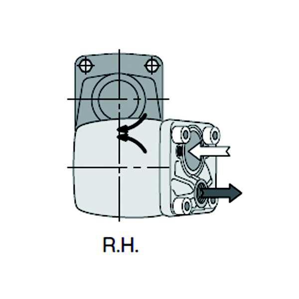
15 Transmission Mounted Hydraulic Pump, Installation Notes All pumps have a Right Hand direction of rotation as seen from the PTO looking to the front of the vehicle. If installing PTO PTR-DM or PTRD-D, a suction fitting and valve are necessary. The following is information about applicable pumps and fittings: Application Chart Parker Pump Options Displacement cc/rev (cu.in/rev) 800 RPM L/min (GPM) RPM L/min (GPM) 1200 RPM L/min (GPM) 1600 RPM L/min (GPM) F (40.9) 32.9 (8.7) 40.9 (10.8) 49.2 (13) 65.9 (17.4) F (59.5) 48.8 (12.9) 60.9 (16.1) 73.4 (19.4) 97.7 (25.8) F (81.6) 64.7 (17.1) 81 (21.4) 97.3 (25.7) (34.3) F (102.9) 14.4 (54.5) (26.7) (32.1) 162 (42.8) F2-42/42 A port 42 (2.6) B port 42 (2.6) 34.1/34.1 (9/9) 41.6/41.6 (11/11) 49.2/49.2 (3/13) 68.1/68.1 (18/18) F2-53/53 A port 54 (3.3) B port 52 (3.2) 41.6/41.6 (11/11) 53/53 (14/14) 64.4/64.4 (17/ /83.3) (22/ 22) Notes USA Date Power Take-off(PTO) Page 15(109)
 B =Frame Rail to PTO mm (inches) VHD-F 13L 4 1900 (74.8) 2020 (79.5) 498 (19.6) VHD-B 13L 4 1340 (52.8) 1460 (57.9) 498 (19.6) VNM / VNR VNL 11L 4 1315 (51.8) 1435 (56.")
16 Layout and Specifications W Front Axle Centerline I Shift PTO Mounting Surface Transmission Model AMT Direct AMT Overdrive Chassis Engine Crank Angle A= AMT 12 Speed mm (inches) A = AMT 13/14 Speed mm (inches) B =Frame Rail to PTO mm (inches) VHD-F 13L (74.8) 2020 (79.5) 498 (19.6) VHD-B 13L (52.8) 1460 (57.9) 498 (19.6) VNM / VNR VNL 11L (51.8) 1435 (56.5) 496 (19.5) 13L (52.8) 1460 (57.9) 498 (19.6) 11L (51.8) 1435 (56.5) 496 (19.5) 13L (52.8) 1460 (57.9) 431 (17.0) USA Date Power Take-off(PTO) Page 16(109)


17 Transmission-driven PTO The transmission-driven PTO is most suitable for trucks used where work is performed while stationary. An example are vehicles equipped with dump beds or hoists. The PTO is engaged by a switch on the instrument panel. A solenoid valve opens and releases compressed air to the PTO which, in turn, meshes with a gear in the transmission. W PTO Usage Transmission-driven PTO The following illustration shows a number of typical applications and the power output requirement in hp (kw) and effective operational time (1) in hours used over a 5-year period. This illustrates the relationship between different body installations and the demands placed on the PTO. W In-power Requirements and Hours in Operation 1. (Time used in hours over 5 years) 5. Logging Crane 2. Blowers 6. Tank, Fuel 3. Roll-off Body 7. Crane 4. Dump Truck 8. Tank, Milk USA Date Power Take-off(PTO) Page 17(109)
18 Power Take-off (PTO), Installation (I-Shift) PTO kit includes transmission drive parts, a solenoid valve, and a switch for a single PTO. PTO kit includes an additional solenoid and switch valve for dual PTO s. Both kits are required for dual PTO s. The electrical directions contained in this bulletin only outline the component installation and setup needed to install a single solenoid driven PTO. If installing a PTO that utilizes two separate solenoids for actuation, more extensive electrical requirements will be necessary. DANGER Do not attempt to repair or service this vehicle without having sufficient training, the correct service literature and the proper tools. Failure to follow this could make the vehicle unsafe and lead to serious personal injury or death. DANGER Before working on a vehicle, set the parking brakes, place the transmission in neutral, and block the wheels. Failure to do so can result in unexpected vehicle movement and can cause serious personal injury or death. DANGER Before beginning any work on any part of the air system, be certain that the air pressure has been released. Failure to do so may cause a component to violently separate, which can result in serious personal injury or death. 1. Torque all fasteners using general tightening torque values unless specified in these instructions. Fastener Size ft-lb (Nm) M6 standard bolt 8.8 7±1 (10±1) M8 standard bolt ±3 (24±4) M10 standard bolt ±6 (48±8) M12 standard bolt ±11 (85±15) M14 standard bolt ±18 (140±25) M16 standard bolt ±26 (190±35) 2. Raise and support the rear of the vehicle. Note: Lift the rear of the truck until the back of the transmission has been raised mm (3-3.5 in) to minimize transmission fluid loss. USA Date Power Take-off(PTO) Page 18(109)

19 3. Drain the air system. 4. Drain the I-Shift transmission air supply tank. Note: This tank is equipped with a pressure protection safety valve and will not drain with the rest of the air system. 5. Remove the PTO mounting surface block off plate from the transmission range housing. Note: Position a drain pan to capture lost transmission fluid. W Snap Ring 2 Thrust Washer 6. Assemble the PTO drive shaft assembly using the PTO drive shaft, bearing, thrust washer and two snap rings. Note: Position one snap ring under the bearing and the other snap ring (1) on top of the thrust washer (2). Note: Using a brass drift, gently drive the bearing into place striking only the inner race. Reposition the drift with each strike, rotating around the bearing. Notes USA Date Power Take-off(PTO) Page 19(109)

20 7. Pack the PTO drive shaft bearing with grease. Note: Use a synthetic based grease such as VOLVO part number or equivalent. W Install the PTO drive shaft assembly in the transmission. Note: Once positioned in the transmission, it may be necessary to gently tap the shaft in. Use a plastic or rubber faced hammer. Note: The bearing is seated when the snap ring on the outside of the bearing touches the mating groove on the transmission. 9. Lubricate the PTO drive shaft pilot bearing. Note: Use a synthetic based grease such as VOLVO part number or equivalent. 10. Install the PTO drive shaft pilot bearing. W Clean the PTO mating surface on the transmission, and then apply a bead of silicone sealant. Note: Only use silicone to seal the PTO mating surfaces. Do not use gaskets or O-rings. USA Date Power Take-off(PTO) Page 20(109)

21 12. Install the air line bracket on the left upper PTO mounting bolt. Install the PTO and tighten the mounting bolts to 85 ± 5 (30 ± 4 ft-lb). W Remove the PTO oil supply line plug from the back side of the transmission oil filter housing. 14. Install the oil feed line fitting into the port on the back side of the transmission oil filter housing. Torque the fitting. Note: Use a copper gasket to seal the fitting Notes USA Date Power Take-off(PTO) Page 21(109)
22 15. Connect the PTO oil feed line to the oil port. Torque the line to 15 Nm (11 ft-lb). W Locate the PTO solenoid wiring harness connectors tied to the transmission wiring harness on top of the transmission. Cut tie straps as needed to free the harness for use. Note: The wiring tags should read PTO1 and PTO2 at the connectors. Note: PTO1 wiring numbers are NA11A1 and NA20A1. PTO2 wiring numbers are NA16A1 and NA17A For a single PTO, install two quick connect air fittings and one pipe plug into the PTO solenoid. For dual PTOs, install an O-ring between the solenoids in place of the pipe plug. Note: The supply line fitting should accept a 9.5 mm (3/8 in) air line, and the outlet fitting should accept a 6.35 mm (1/4 in) air line. W Plug for single or O-ring for dual 2 Outlet fitting 1/4 3 Supply line 3/8 USA Date Power Take-off(PTO) Page 22(109)
. W4003019 USA138933449 Date 7.")
23 18. Install the PTO solenoid to the bracket and torque the bolts to 9 Nm (80 in-lb). W Remove the two, top left range housing mounting bolts. 20. Install the PTO solenoid bracket using the range housing bolts. Torque the bolts to110 Nm (81 ft-lb). W USA Date Power Take-off(PTO) Page 23(109)
 air line. 23. Install a 6.")
24 21. Connect PTO1 wiring harness to the solenoid. Note: The wiring tags should read PTO1 and PTO2 at the connectors. Note: PTO1 wiring numbers are NA11A1 and NA20A1. PTO2 wiring numbers are NA16A1 and NA17A Install a 90 air line quick connect fitting into the PTO. Note: The fitting should accept a 6.35 mm (1/4 in) air line. 23. Install a 6.35 mm (1/4 in) inch air line from the solenoid to the PTO. Note: Route the air line away from the moving parts and secure to the mounting bracket with tie straps. 24. Remove the plug from the available 9.5 mm (3/8 in) inch air line port on the pressure protection manifold, found on the left inner frame rail. 25. Install the solenoids. Install the 9.5 mm (3/8 in) air supply line to the pressure protection manifold and then connect it to the solenoid. Note: Route the air line away from any moving parts and secure using tie straps. W W USA Date Power Take-off(PTO) Page 24(109)
25 26. Remove the plug from the available 3/8-inch air line port on the pressure protection manifold (found on the left inner frame rail). Insert the air line and route it to the solenoid inlet 3/8 port. 27. Pressurize the air system and check for leaks. Note: If any leaks are found, drain the air tank and repair the leak. Re-test until no leaks are found. 28. Remove the supports and lower the vehicle. 29. Should the transmission require additional oil see charts below. Park the vehicle on a level surface and check the transmission oil level through the sight glass on the right side of the transmission. Add Volvo-approved synthetic transmission oil as needed. Note that the drain plug indicates the type of oil used in the transmission. Silver Drain Plug Brass Drain Plug , SAE50 I-Shift Heavy Duty VPO120549, 75W-80 I-Shift Standard Volvo Oil Types and Part Numbers Oil Weight SAE50 Part Number and Alternative or Mobile Delvac Synthetic Transmission Oil V50 75W-80 VPO or Mobile Delvac Synthetic Transmission Oil V30 Notes USA Date Power Take-off(PTO) Page 25(109)


26 Note: Fill the transmission until the fluid level is between minimum and maximum of the sight glass. Note: Do not reuse old oil from the I-Shift transmission. Always use new oil when filling. Note: 1 2 L (1 2.1 qt) of fluid may be lost during the installation. W A 1B Drain plug Drain plug 2 Sight glass 3 Fill plug T USA Date Power Take-off(PTO) Page 26(109)

27 30. Remove the fuse relay center (FRC) cover in the cab. 31. Install a 5 amp fuse in fuse location F40 of the FRC. W Install an ISO relay in relay location R7 of the FRC. 33. Install the FRC cover. 34. Remove the dash switch blank from either position 3 or 5 on the dash board. The PTO switch connector is in the cab wiring harness and should be located behind this general location. W USA Date Power Take-off(PTO) Page 27(109)
28 35. Install the PTO switch ( ) in position 3 or 5, depending on which location is available. 36. Using the scan tool, flash the transmission control module (TCM) with the appropriate software for a single PTO. Con tact the help desk for further assistance.. Note: The appropriate software is dependent upon how many solenoids are being used to actuate the PTO (single or dual solenoids), not the outputs on the PTO. 37. After the TCM has been flashed with its software, it is necessary to perform the Transmission and Clutch Calibration using the scan tool. 38. Perform PTO parameter programming. For more information, refer to the PTO Programming bulletin found in the electrical section of the Body Builders Manual. Note: It will be necessary to change the vehicle electronic control unit Vehicle ECU default parameter for PTO position mounting from engine1 to transmission Run the vehicle and re-check the transmission fluid level. Top off the transmission as needed so the fluid level is between minimum and maximum of the sight glass. Note: The PTO shares the transmission fluid for lubrication. The PTO will retain about.75 liters (.8 qts.), of transmission fluid after initially being run. Always top off the transmission fluid after installing a new PTO. Notes USA Date Power Take-off(PTO) Page 28(109)

29 Diesel Exhaust Fluid (DEF) Cooling Lines, Side Mounted PTO This kit is being released in order to provide a solution for customers requiring a side mounted PTO on mechanical transmissions. Currently, if a PTO is mounted on the transmission it will interfere with the urea cooling lines that are routed down the right side of the frame. This kit allows the customer to remove the hard piping associated with the urea cooling lines and replace them with flexible hoses that prevents the previously mentioned interference. Mechanical Transmission PTO Cooling Line Routing Kit D13 Contents D11 Contents Part Number Part Description Quantity Part Number Part Description Quantity Rubber Hose Rubber Hose Cable Tie Rubber Hose Bracket Cable Tie Bracket Bracket Bracket Bracket Clamp Bracket Flange Screw Clamp Lock Nut Flange Screw Flange Screw Lock Nut Lock Nut Flange Screw Connector Lock Nut Hose Clamp Connector Hose Clamp 2 W Cooling Line Routing USA Date Power Take-off(PTO) Page 29(109)
30 Rear Engine PTO, Installation When installing a rear engine PTO on a D11F or D13F engine, use the following parts information. PTO Spline Part Number Description QTY REPTO Unit 1 D11F DIN O-Ring Bolt Bolt REPTO Unit 1 D11F SAE O-Ring Bolt Bolt REPTO Unit 1 D13F DIN O-Ring Bolt Bolt REPTO Unit O-Ring 1 D13F SAE Bolt Bolt Protecting Screen 1 Engine Mounted Power Take-off Speed ratio: 1:X.x (1: = engine, X.x = power take-off) Engine Speed ratio Direction of rotation 1 Max permissible torque ft-lb (Nm) 2 Power take-off D11 1:1.08 < 5 km/h (3 mph) 1000 (738) > 5 km/h (3 mph) 650 (479) PTR-xxx D13F 1: > 5 km/h (3 mph) 650 (479) PTR-XXX + EPTT650 < 5 km/h (3 mph) 1000 (738) PTR-XXX + EPTT Counter clockwise when facing back of engine 2 The engagement of the hydraulic pump must not give any pressure peaks exceeding the rated pressure. Note: Low stiffness of the prop shaft and big inertia on the pump will give low resonance frequency, which can be triggered by the frequency in the engine. The engagement time has to be so long that no pressure peaks will occur, and the best way to verify this is to measure the pressure close to the pump. USA Date Power Take-off(PTO) Page 30(109)

31 Volvo REPTO (Clutch Independent Power Take-offs) Volvo offers two (2) types of engine REPTO (clutch independent) for the D11 and D13 engines that are capable of a single DIN or Flange drive. REPTO The Volvo REPTO is driven by the engine gear train at the rear of the engine. This clutch independent design consists of a bearing housing that is mounted directly on the right rear side of the engine gear train. Since the power is taken directly from the engine, this PTO can be utilized while the vehicle is being driven or stationary for maximum versatility. The power takeoff has few moving parts for high performance. It is always more cost effective to order an engine with the REPTO installed at the time the engine is built, but it can be installed as an aftermarket upgrade. Clutch independent PTOs are also suitable for engagement and disengagement from outside the vehicle. When the PTO is driving a hydraulic pump, a bypass valve is needed to control when hydraulic fluid flow is needed. For vehicles that require constant access to PTOs, clutch independent is the only option. Note: Unlike the multiple output options available with an I-Shift PTO, the only way to provide a dual hydraulic circuit with a single engine mounted PTO is to use a dual flow hydraulic pump such as the Parker F2 series. W Engine Power Takeoff Weight lbs. PTO Drive Type Type Type Dimension Speed Ratio Direction of Rotation Torque Max (lbs-ft) D11 PTER-DIN 66.0 Direct DIN <3mph=740 Same as PTER-DIN 66.0 Direct DIN 5426 D engine PTER Flange SAE 1410 >3mph=480 REPTO Application Since this PTO is capable of being operational while driving and at a standstill, it is ideally suited to the following applications. Concrete Mixer Typically a driveshaft connection is used in this application to drive the pump that is part of the mixer body installation. Snow Plow Typically a direct connect single or dual valve pump to power the plow blade and salt spreaders. Refuse Typically a direct connect single or dual valve pump to power the body packer between collections. USA Date Power Take-off(PTO) Page 31(109)
32 Rear Engine-mounted PTO with Splined Shaft Groove (Female) DIN 5462 REPTO with splined groove is a clutch independent, rear mounted, engine power take-off (PTO). The PTO consists of a bearing housing that is mounted on the right rear side of the engine gear train. It is suited to types of transport in which the power take-off must be clutch independent. This means that the power is taken directly from the engine, and the engagement/disengagement can be done while the vehicle is being driven. It can also operate both when the vehicle is in motion or stationary. The PTO has few moving parts high performance and is especially suited to VOLVO's engines for high availability. T Shown with optional direct mount pump Notes USA Date Power Take-off(PTO) Page 32(109)
33 Rear Engine-mounted PTO with Flange SAE 1410/ ISO 7647 REPTO with flange is a clutch independent, rear-mounted, engine power take-off with a SAE 1400 flange connection for shaft driven accessories. The power take-off consists of a bearing housing that is mounted on the right rear side of the engine gear train. It is suited to types of transport in which the power take-off must be clutch independent. This means that the power is taken directly from the engine. The power take-off can operate both when the vehicle is in motion and when it is stationary, resulting in high vehicle productivity. W Rear-Mounted Engine PTO (D13 engine) Notes USA Date Power Take-off(PTO) Page 33(109)
34 SAE Flanges W Flange SAE 1400 W Flange SAE 1300 USA Date Power Take-off(PTO) Page 34(109)
35 Rear Engine PTO Access Removal of the passenger s seat and rolling back the floor mat is necessary to utilize the rear engine PTO access. W Control plate for REPTO Engine Access Plate(s) A Location of Engine Access Plate(s) Note: To remove the Engine Access Plate, the Floor mat and Passenger Seat must be removed. USA Date Power Take-off(PTO) Page 35(109)
36 Rear-mounted Engine PTO Trucks used for certain applications, such as cement mixers or dump trucks, may be equipped with a rear mounted engine PTO (REPTO). PTOs of this type are installed on the rear of the engine, and are driven by the crankshaft. They are intended for use when the vehicle is moving or stationary. REPTOs have been designed to accomplish a number of performance-related objectives: They have eliminated unnecessary parts (e.g., additional Front-mounted PTO equipment). They deliver efficient, clutch independent power. They allow specification of a lengthened wheelbase without exceeding overall length restrictions. Example: two trucks with the same frame length must meet the same overall length of 10 m (40 ft). The truck with a front-engine PTO requiring a hydraulic pump in front of the cab (or bumper) will limit the wheelbase approximately cm (18 21 in) compared to the vehicle with REPTO. This results in an increase in payload under the federal Bridge Law of kg ( lb). This performance is possible because REPTOs are designed as an integral bearing housing that is mounted on the right, rear of the engine. Note: The REPTO rotates in the same direction as the engine. Note: The REPTO access hatch is tied to the REPTO variant. Whenever a REPTO is requested the access hatch is provided. Therefore, the customer does not need to request the hatch. Benefits of REPTO include: Eliminate the need for extended frame or bumper. Permits shorter hydraulic lines. Simplifies maintenance (REPTO need not be removed for clutch service) Eliminates need for modification to radiator and radiator supports for PTO shaft clearance. Notes USA Date Power Take-off(PTO) Page 36(109)
37 REPTOs permit the operator to engage or disengage the PTO even when the vehicle is moving. Unlike transmission mounted PTOs, REPTOs are dependent only on the engine. VOLVO D11 Specifications Location Type Flange Connection Right rear side of engine gear train Clutch independent power take-off SAE 1350/ Bolt DIN Mounting 5462/ISO 7653 Engine D11 Gear Ratio (Engine:PTO) 1:1.08 Max Torque Stationary Max Torque >5 kph (3 mph) Weight 740 ft-lb (1003 Nm) 480 ft-lb (651 Nm) 15.5 kg (34.2 lb) W Rear-Mounted Engine PTO (D11/D13 engine) USA Date Power Take-off(PTO) Page 37(109)
38 VOLVO D13 Specifications Location Type Flange Connection Right rear side of engine gear train Clutch independent power take-off SAE 1350/ Bolt DIN Mounting 5462/ISO 7653 Engine D13 Gear Ratio (Engine:PTO) 1:1.08 Max Torque Stationary Max Torque >5 kph (3 mph) Weight 740 ft-lb (1003 Nm) 480 ft-lb (651 Nm) 15.5 kg (34.2 lb) T Rear-Mounted Engine PTO (D11/D13 engine) Hydraulic Pump Flow D11 Engine, (GPM) at Pump Speed (rpm) Pump Speed (rpm) Parker/VOAC Pump¹ Ratio 800 L/min (gpm) 900 L/min (gpm) 1000 L/min (gpm) 1200 L/min (gpm) 1400 L/min (gpm) 1600 L/min (gpm) F1 61 1: (13.5) 58 (15.3) 64 (16.9) 77 (20.3) 90 (23.8) 103 (27.2) F1 81 1: (18.8) 79 (20.9) 88 (23.2) 106 (28.0) 123 (32.5) 141 (37.2) F : (23.5) 100 (26.4) 111 (29.3) 133 (35.1) 156 (41.2) 178 (47.0) F2 42/42 1: /35 (9.8/9.2) 42/40 (11.1/10.6) 46/44 (12.2/11.6) 56/53 (14.8/14.0) 65/62 (17.2/16.4) 74/71 (19.5/18.8) F2 53/53 1: /45 (12.4/11.9) 52/51 (13.7/13.5) 58/56 (15.3/14.8) 70/67 (18.5/17.7) 82/79 (21.6/20.9) 93/90 (24.6/23.8) USA Date Power Take-off(PTO) Page 38(109)
39 Hydraulic Pump Flow D13 Engine, (GPM) at Pump Speed (rpm) Pump Speed (rpm) Parker/VOAC Pump¹ Ratio 800 L/min (gpm) 900 L/min (gpm) 1000 L/min (gpm) 1200 L/min (gpm) 1400 L/min (gpm) 1600 L/min (gpm) F1 61 1: (13.5) 58 (15.3) 64 (16.9) 77 (20.3) 90 (23.8) 103 (27.2) F1 81 1: (18.8) 79 (20.9) 88 (23.2) 106 (28.0) 123 (32.5) 141 (37.2) F : (23.5) 100 (26.4) 111 (29.3) 133 (35.1) 156 (41.2) 178 (47.0) F2 42/42 1: /35 (9.8/9.2) 42/40 (11.1/10.6) 46/44 (12.2/11.6) 56/53 (14.8/14.0) 65/62 (17.2/16.4) 74/71 (19.5/18.8) F2 53/53 1: /45 (12.4/11.9) 52/51 (13.7/13.5) 58/56 (15.3/14.8) 70/67 (18.5/17.7) 82/79 (21.6/20.9) 93/90 (24.6/23.8) BOC Crossmember For REPTO with/without Mixer Body Plates Sales Code: OA-AC BOC Crossmember for PTO with Mixer Plates OA-AD BOC Crossmember for PTO without Mixer Plates AX-AA Flip Overhang Crossmember Upside Down BOC crossmember for PTO with Mixer Body Plates (OA-AC) and BOC crossmember for PTO without Mixer (OAAD) Intermediate crossmember offerings are available in VHD Models with REPTO or Allison PTO configurations for Mixer use. These options allow body companies to mount the mixer PTO pump on the VOLVO crossmember. An inverted intermediate overhang crossmember option, Flip Overhang crossmember Upside Down (AXAA), is also available that will allow for mixer booster axle cylinder clearance. When this option is specified the intermediate overhang crossmember is mounted upside down to prevent the mixer cylinder from interfering. W W Crossmember Crossmember and Body Plate USA Date Power Take-off(PTO) Page 39(109)
40 Front-mounted Engine PTO W The front-mounted PTO is suitable for the following applications: Refuse Dump body with spreading apparatus Roll on/off, hook lifts Municipality trucks with multiple hydraulic equipment needs, snow plows, cranes, dump bodies, etc. Notes USA Date Power Take-off(PTO) Page 40(109)
41 Front PTO Configuration, Axle Back Volvo VHD Only W Fig. 1 Front PTO, Axle Back, With 930 Sq. in. Radiator 1 PTO shaft mounting surface. 2 Centerline of crankshaft at 4. 3 Position of engine rear face of flywheel housing. 4 Centerline of front axle. 5 See Fig. 4 on page Series shaft shown. 7 Centerline of PTO driveshaft (horizontal) A Dimension (see table below) Dimension Axle Forward mm (in.) Axle Back mm (in.) A 220 (8.7) 778 (30.6) Max Torque Max Power 678 Nm (500 ft-lb) 134 kw ( rpm USA Date Power Take-off(PTO) Page 41(109)
42 W Fig. 2 Front PTO, Axle Back, With 1240 Sq. in. Radiator 1 PTO shaft mounting surface. 2 Centerline of crankshaft at 4. 3 Position of engine rear face of flywheel housing. 4 Centerline of front axle. 5 See Fig. 6 on page Series shaft shown. 7 Centerline of PTO driveshaft (horizontal) A Dimension (see table below) Dimension Axle Forward mm (in.) Axle Back mm (in.) A 206 (8.1) 766 (30.2) USA Date Power Take-off(PTO) Page 42(109)
43 W Fig. 3 Adapter PTO Drive Coupling (1350/1410), 1:2 1 4 x 7/16 20UNF-2B PC Diameter W Fig. 4 Exploded View, Front PTO Drive Adaptation, With 930 Sq. in. Radiator 1:2 1 PTO Shaft Flange Mounting Surface 2 Adapter PTO Drive Coupling 3 Companion Flange with Base Engine 4 Engine Timing Case Cover USA Date Power Take-off(PTO) Page 43(109)
 Bolt part number 959265, quantity 6 each W4111399 Fig.")

44 W Fig. 5 Crankshaft Vibration Damper Step ± 5 Nm (26 ± 4 ft-lb) Step ± 10 Nm (66 ± 7 ft-lb) Bolt part number , quantity 6 each W Fig. 6 Exploded View, Front PTO Drive Adaptation, With 1240 Sq. in. Radiator 1 PTO Shaft Flange Mounting Surface 2 Adapter PTO Drive Coupling 3 Fan Drive Pulley 4 Crankshaft Damper USA Date Power Take-off(PTO) Page 44(109)
45 W Fig. 7 Partial Front View, With 930 Sq. in. Radiator (VHD Only) 1 RH Siderail 2 Tube diameter: 89 mm (3.5 in.) 3 Swing diameter: 1410 Series joint, 124 mm (4.9 in.) 4 Clearance to radiator with 1410 Series shaft tube in horizontal position. B Dimension (see table below) Dimension D13 mm (in.) B 17 (0.7) Notes USA Date Power Take-off(PTO) Page 45(109)
46 W Fig. 8 Partial Front View, With 1240 Sq. in. Radiator (VHD Only) 1 RH Siderail 2 76 mm Shaft Tube Clearance to Cooling Package 3 Swing diameter: 1410 Series joint, 124 mm (4.9 in.) Engine D11 / D13 Flange SAE 1400 / 1100 Max output torque while stationary (vehicle speed < 3 mph) Max output torque while moving (vehicle speed > 3 mph) 600 ft-lb (813 Nm) 284 ft-lb (385 Nm) USA Date Power Take-off(PTO) Page 46(109)
47 Hydraulic Pumps Abbreviations HPE = Hydraulic pump mounted to an engine power take off (Hydraulic Pump Engine mounted). HPG = Hydraulic pump mounted to a gearbox power take off (Hydraulic Pump Gearbox mounted). Pump Connection There are two types of connections for hydraulic pumps: Din Drive pumps Flange mounted Din Drive Pumps Plugged-in pumps are connected directly to the power take-off via a splined shaft. Connection is done according to DIN5462/ISO 7653 standard 8 X 32 X 36 mm spline shaft. The VP1 and F1 Plus pumps are available for plugged-in mounting. T Din mount Flange Mounted Pumps The hydraulic pumps can also be connected to the power take-off via a propeller shaft. Connection is done to a flange according to SAE 1300 or SAE 1400 standard. The VP1 and F1 Plus pumps are possible to connect to a propeller shaft. T Flange mounted USA Date Power Take-off(PTO) Page 47(109)
48 Hydraulic System and Pumps Dimensioning of Hydraulic System and Hydraulic Pumps Note: The body builder should enclose an information binder, delivered with the truck, including hydraulic system data (system dimensioning description and dimensioning criteria). Service, function and safety descriptions should also be enclosed. It is important to dimension an optimum hydraulic system, and to specify the correct pump size to provide sufficient oil flow and prevent overloading of the power take-off. Pipes, Lines and Hoses DANGER Hoses and pipes should not be routed too near the warm points in the truck. Avoid crossed pipes which could cause chafing. Failure to follow this guide line increases the risk of fire if leakage occurs, and allows undue heat transfer to the hydraulic oil. Connected to the hydraulic pump are a high-pressure hose, suction and drain lines. When dimensioning the hydraulic system, it is important that: Hoses and lines must be connected to the pump with unions. O-ring seals must be used between pump and union. Tapered fittings should be avoided. Teflon tape or similar must not be used since pieces can break off and get into the hydraulic system and eventually cause damage. If steel piping is used, it must be installed so that movements and vibrations do not cause leakage. Normally hoses must be used nearest the pump. Oxide scale must be removed from pipes which have been heat-bent or welded. Flush or blow the pipes clean before installing them. High-Pressure Hose These hoses must have a minimum of four steel wire coil inserts in order to withstand the high pressure in the hydraulic system. When mounting a high-pressure hose: Make sure the hoses are not twisted when connected up. Make sure the hoses are long enough. Strive to get as few bends as possible on a hose. Avoid kinks by using correct unions. Only pressed unions may be used when replacing hose unions. Note: Check for oil leakage and for high noise levels in the system when the truck is in motion. USA Date Power Take-off(PTO) Page 48(109)
49 Suction Line The suction line is made of piping or armored hose which retains its shape even when there is vacuum in the line. To avoid cavitation: The suction line should be as short as possible and should not exceed 4 meters (13.12 ft.). In the event longer lines are required, larger line dimensions must be used. The suction line should connect to the bottom of the tank and must be correctly tightened to prevent air getting into the oil. The suction line must have a wide diameter and must be free from kinks and constrictions. Do not use reducer fittings with restrictions. Note: Avoid suction lines of high-pressure hooks and hooks made locally from pipe pieces welded together. They could cause unnecessary suction resistance. Suitable suction line sizes at different flow quantities and with a flow speed of less than 0,8 m/s: Inner diameter Ø mm (inches) Flow up to liter/minute (gallons/minute) 50 (2.0) (0 32) 64 (2.5) (27 40) 75 (3.0) > 150 (40) Drain Line and Bypass Valve If the hydraulic pump is installed to a constantly running PTO (i.e. engine PTO), it is provided with a bypass valve. The bypass valve reduces the oil flow through the pump to obtain proper lubrication, low heat generation and to avoid cavitation. Fixed Displacement Pump HPE-FXX (F1 single flow) In order to prevent heat build-up in the pump during transportation, it is important that at least 5 liter/minute (1.32 gallons/minute) comes out of the filter at q (refer to the schematic below). This applies to an open center system when the valve is in the bypass mode (non-activated solenoid). Note: If the flow at q is less than 5 liter/minute (5.28 quarts/minute) (caused e.g. by a high pressure drop in the main system) when the valve is in the bypass mode or if the hydraulic system is of the closed center type, then an external drain line must be installed from the bypass valve drain port directly to the hydraulic tank. HPE-TXX (F2 twin flow) In order to secure a cooling flow through the system, a separate drain line is already connected to the bypass valve from factory and the other end of the hose is temporary plugged. At final assembly the hose should be connected to the hydraulic tank, entering below oil level (preferable to the filter housing on the oil tank). USA Date Power Take-off(PTO) Page 49(109)
50 Bypass Valve For the fixed displacement hydraulic pumps, the bypass valve is attached directly on top of the end cap of the hydraulic pump. It is electrical operated and the valve function must only be activated or released at no-load (below 20 bar) system pressure. For F2- twin flow hydraulic pump it can be used when, temporarily, one of the two circuits is not required; the power loss is thus reduced as the non-required flow is not forced through lines and open center valves. 1 Pilot operated check valve 2 Solenoid valve 3 Directional control valve ( open center ) 4 Hydraulic pump 5 Valve block 6 Drain port 7 (External line) T HPE-FXX Notes USA Date Power Take-off(PTO) Page 50(109)
51 Variable Displacement Pump HPE-VXX (VP1) At final assembly, since the control valve on the hydraulic pump is not internally drained, there must be an external drain line installed between port T and the hydraulic tank. Bypass Valve For variable displacement pump the bypass is, from factory, attached to the temporary oil reservoir and connected to the hydraulic pump via a hose to the port for gauge outlet, (on VP1-45 and VP1-75 port beside suction port and on the VP1-120 port M on the control valve). The valve, which requires no additional control valve, allows the pump to operate on- or off-load up to its maximum self priming speed. When a load sensing valve function is engaged, the bypass flow is cut off (as port 'X' is being pressurized). 1 Hydraulic pump 2 Nipple with orifice 3 Bypass valve 4 Load sensing valve 5 Load sensing (LS) signal W HPE V120 USA Date Power Take-off(PTO) Page 51(109)
52 Hydraulic Oil Tank The tank must be large enough to avoid cavitation and overheating. A suitable volume is 1,5 times the nominal pump flow per minute. The tank includes: 1 Air filter, fitted (as required) in a tube and provided with a non-return valve 2 Level gauge 3 Suction connector equipped with full-flow tap 4 Angled, perforated plate on which air bubbles accumulate and rise to the surface 5 Return oil filter T Illustration is for reference only. May differ on specific vehicle. When installing a hydraulic tank: The volume of the hydraulic tank must be dimensioned 1,5 times the nominal pump flow during normal working conditions. Make sure that the placing of the hydraulic tank does not limit the performance of the hydraulic pump. For example: The suction fitting must not be placed below the inlet of the return pipe. It is important that the deaeration surface is big enough. Prevent external dust and dirt from entering the hydraulic system. The inside of the tank must be well cleaned. To prevent dust getting into the system, the air filter should have the same filtration degree as the return oil filter. Oil is topped-up through the return oil filter, preferably via a rapid joint on the return line where the oil can be pumped in. Check oil level and ensure that it is oil of recommended type and viscosity. USA Date Power Take-off(PTO) Page 52(109)
53 Return Oil Filter Note: The filter must be replaced at least once a year. A return oil filter should be installed in the tank or in the return line. The filter should be dimensioned for a capacity which is approximately twice that of the pump flow. Recommended filtration level: A 28 micron filter should be used with lower pressures of bar ( psi). A 10 micron filter should be used with higher pressures of bar ( psi). Check return pipe and filter condition and check for oil leakage. Hydraulic Oil Note: Do not mix oils of different quality. Hydraulic fluids type HLP (DIN51524), automatic transmission fluid (ATF) Dextron II and engine oil type API/CD can be used. Recommended viscosity: mm²/s ( inches²/s) (cst). Starting Up CAUTION Make sure the suction connector always is below the minimum level of the hydraulic oil. Failure to do so may result in component damage. Make sure the entire hydraulic system is clean before filling it with a recommended fluid. In particular the pump, which must be purged to remove any entrapped air in the pump housing (use the uppermost purge port). Failure to do so may result in component damage. Notes USA Date Power Take-off(PTO) Page 53(109)
54 Calculation of Hydraulic Pump Size The following information is required to dimension the hydraulic system: Oil flow Q=l/min (Quarts/min.), to the equipment Oil pressure p=bar (psi), to do the work intended Permissible torque or power taken from the engine Permissible pump speed PTO Gear ratio Control the pump environment with the Parker calculation program. Go to Introduction on the VBI homepage, choose Software requirement and click on Parker. Engine Speed Engine speed limit for engine mounted hydraulic pumps Vehicles specified with engine mounted hydraulic pumps will always have a maximum engine speed (rpm) pre set from factory. Depending of pump size and if the vehicle is equipped with Body Builder Module (BBM) or not, the setting is between rpm. This has been done by using data parameters in the vehicle control unit, and when the hydraulic pump is in service, the maximum engine speed cannot be overridden by pressing the throttle. If the hydraulic system is designed in such way that the self-suction speed of the hydraulic pump is reduced, then the limited value should be modified using Premium tech tool. Engine Speed Control Check that the permissible speed, specified by the pump manufacturer on the pump, is not exceeded. Pump speed per minute n is governed by engine speed ne and power take-off gear ratio Z: n = Pump speed (rpm) ne = Engine speed (rpm) Z = Power take-off gear ratio USA Date Power Take-off(PTO) Page 54(109)
55 Pump Speed The maximum (self-suction) speeds given in the catalogue apply at 1.0 bar (14.5 psi) (abs.) intake pressure. To achieve correct pump speed the following is required: Oil level approx. 0.5 m above pump inlet Correctly dimensioned suction pipe Original suction nipple Correctly designed hydraulic fluid reservoir The flow speed in the suction pipes should be less than 1 m/s (39.36 in/hg). Poor suction conditions lead to cavitation, high noise levels, shorter operational lifetime and, in the worst case, pump failure. Pump Capacity The pump capacity or size D cm³/rotation (inches³/rotation) should be able to give sufficient oil flow Q l/min (inches/min.) for the equipment. The choice of size depends on the oil flow required, engine speed and power take-off gearing. A small pump can give a large oil flow if the power take-off gear ratio is large, or if the engine speed is high. Pump size is calculated as: n = Pump speed (ne x Z) D = Pump size cm³/rotation (inches³/rotation) ne = Engine speed Q = Oil flow l/min (quarts/min.) Z = Power take-off gear ratio ηv = volumetric efficiency Torque Control A certain torque, Mku is required from the power take-off at the pump shaft to drive the pump. This torque must not exceed the permissible torque for the power take-off. Expressed in Nm, this torque is: Mku = Torque at power take-off (Nm) D = Pump size cm³/rotation (inches³/rotation) p = Hydraulic working pressure bar (psi) Mku, till. = Permissible torque for the power take-off Nm (ft-lb) ηhm = Mechanical efficiency < = Less than USA Date Power Take-off(PTO) Page 55(109)
56 Torque Control, Engine Torque control of the engine Mmot must not exceed the permissible torque for the engine (please refer to Body builder instructions Power take-off, performance ) at a given engine speed. Engine torque is equal to power take-off torque x gear ratio. Mmot = Engine torque Nm (ft-lb) Z = Power take-off gear ratio Mku = Torque at power take-off Nm (ft-lb) Mmot, till. = Permissible engine torque Nm (ft-lb) < = Less than Power Requirements The power N needed to drive the pump is proportional to the flow and working pressure and inversely proportional to the efficiency of the pump η. Check that pump power curve, to see that it has the capacity needed to provide the calculated power N. N = Power kw (hp) Q = Flow through pump l/min (quarts/min.) p = Working pressure bar (psi) ηt = Overall pump efficiency(app. 0.95) Notes USA Date Power Take-off(PTO) Page 56(109)
57 Example 1 (Dump), Selecting Pump Size Clutch Dependent PTO Operating conditions Flow Pressure: Engine rpm: l/min (63 85 quarts/min.) 230 bar (3335 psi) 800 rpm Determine the Pump Speed n = ne x Z=800 x 1.53 = 1200 rpm PTO ratio: 1:1.53 Choosing the pump size Select F1-61 and check torque and power. Torque Requirement of the Pump Power Requirement of the Pump Notes USA Date Power Take-off(PTO) Page 57(109)
58 Example 2 (General Crane), Selecting Pump Size Clutch Independent PTO Operating conditions Flow Pressure: Engine rpm: 80 l/min (84 quarts/min.) 250 bar (3626 psi) rpm Determine the Pump Speed n = ne x Z = 800 x 0,97 = 800 rpm PTO ratio: 1:0.97 Choosing the Pump Size Select F1-101 and check torque and power. Torque Requirement of the Pump Power Requirement of the Pump Notes USA Date Power Take-off(PTO) Page 58(109)
59 Pump Types The following pump types are available from VOLVO: Pumps with fixed displacement Pumps with variable displacement Fixed Displacement Pump This type of hydraulic pump is adapted for a single circuit system with fixed volume. The fixed displacement pump consists internally of one or two single circuit(s), from the suction port to the pressure port(s). Examples: HPE / HPG-F61 (Parker F1-61) HPE / HPG-F81 (Parker F1-81) HPE / HPG-F101 (Parker F1-101) HPE-T53 (Parker F2-53/53) HPE-T42 (Parker F2-42/42) Variable Displacement Pump This type of hydraulic pump is also adapted for a single circuit system, from the suction port to the pressure port, but with variable displacement. When installed in a load sensing system, the variable displacement pump (VP1) supplies the correct amount of flow required by the various work functions currently engaged. This means that the energy consumption and heat generated are minimized and much reduced in comparison with a fixed displacement pump used in the same system. Examples: HPE / HPG-V120 (Parker VP1-120) Notes USA Date Power Take-off(PTO) Page 59(109)
60 Delivery Conditions for Factory Installed Hydraulic Pumps CAUTION Hydraulic pumps must never be in use without oil flow in the hydraulic system. Failure to do so may result in component damage. For Trucks with Transmission Mounted PTO: To prevent the possibility to engage the hydraulic pump before definitive assembly, the following is done from factory: The PTO magnetic valve outlet is blocked up by a hexagon socket plug. One or two valves is plugged, depending on type of PTO. The valve nipple, which the body builder should connect, is placed in a plastic bag and strapped on the end of the pneumatic hose at magnetic valve For Trucks with Engine Mounted PTO: The hydraulic pump is always engaged; therefore sufficient lubrication is needed continuously for the pump. To establish lubrication during transport from factory to final assembly at body builder, a temporary hydraulic transport kit is added at the factory. The components in the kit (tank, hoses and unions) should be replaced; they are not dimensioned for the working pressure in the definitive hydraulic system. Note: The replacement must be performed in particularly clean conditions. Dirt and other contamination which finds its way into the hydraulic system could easily cause severe damage. Temporary hydraulic transport kit There are two different temporary kits, and the size of the oil reservoir differs: 1. Temporary hydraulic transport kit (for fixed displacement pumps) Engine D11/D13 (HPE-FXX) Amount of oil if refill is needed 0.3 ± 0.05 liter (0.32 ± 0.05 quarts) T USA Date Power Take-off(PTO) Page 60(109)
61 2. Temporary hydraulic transport kit (for variable displacement or customer adaptation installed hydraulic pump) Engine D11/D13 Amount of oil if refill is needed Minimum level on reservoir should be achieved after the engine is started. Approximately 10 liter (10.5 quarts). T T D11 Engine With Engine Mounted PTO (D11 and D13) Connections to the Engine Mounted Hydraulic Pump A Factory delivered Factory installed connection from the hydraulic pump. Dimension 25S (M36 x 2). B Body builder Body builder's connection. Hose connection with 24 cone. C Suction side Smallest external connection diameter see table below: Hydraulic pump HPE-V45 HPE-V75 HPE-FXX HPE-TXX HPG-FXX HPE-V120 HPG-V120 Diameter X mm (inches) 50 (1.97) 63 (2.48) 75 (2.95) T X = smallest external connection diameter. USA Date Power Take-off(PTO) Page 61(109)
62 Installation Requirements for Hydraulic Pump at Final Assembly CAUTION Hydraulic pumps must never be in use without oil flow in the hydraulic system. Failure to do so may result in component damage. Fixed displacement pump, HPE-FXX (F1 single flow) Remove the temporary oil reservoir kit, tank, fittings and hoses are not designed for use in high pressure installations. See that enough oil flow (minimum 5l/min) is running in the final hydraulic system back to the hydraulic tank when the hydraulic pump is running unloaded. If not, a drain line must be installed from bypass valve to hydraulic tank entering below oil surface (to avoid foaming the oil). Fixed displacement pump, HPE-TXX (F2 twin flow) Remove the temporary oil reservoir kit, tank, fittings and hoses are not designed for use in high pressure installations. The drain hose from bypass valve, supplied loose from factory, must be connected to hydraulic tank entering below oil surface (to avoid foaming the oil). Dimension of hose fitting is M12x1,5 DIN 20078N. It is allowable to shorten the drain hose, but a new fitting must be attached in a proper way. Variable displacement pump, HPE-VXX (VP1) Remove the temporary oil reservoir kit, tank, fittings and hoses are not designed for use in high pressure installations. The bypass valve attached to the tank together with the hose between pump and by pass valve shall be kept and a drain hose should be connected between port T and hydraulic tank. It is allowable to shorten the drain hose between pump and bypass valve but a new fitting (M12x1,5 DIN 20078N) must be attached to fit onto fitting in bypass valve. The load signal on its way to port LS at the load sensing regulator on the hydraulic pump shall be connected in port X on the bypass valve as well. A drain line must be installed between port T on the hydraulic pump and the hydraulic tank since the load sensing regulator is not internally drained. Permissible Pump Bending Torque The hydraulic pump mounted to a power take-off causes bending torque at the power take-off. USA Date Power Take-off(PTO) Page 62(109)
63 A transmission mounted power take-off has the following maximum permissible torque: PTR/PTRD/PTPT/PTR with AMT D and AMT F Transmission PTO Maximum bending torque ft-lb (Nm) PTR/PTRD 30 (40) PTPT-D 30 (40) PTR 30 (40) Calculation of Pump Bending Torque Torque is calculated with the formula below: Mb Bending moment at pump connection to power take-off (Nm). m g A Pump weight (kg). Normal acceleration = 9.81 N/kg. Distance between pump center of gravity and anchorage on power take-off (m). Note: This calculation method is used irrespective of PTO/pump location. T USA Date Power Take-off(PTO) Page 63(109)
64 Propeller Shaft Installation If a power take-off with coupling flange is to be used, the pump is installed by means of a bracket, either on an existing crossmember or on the sub-frame. An alternative method is to install an extra crossmember and install the pump on it. In this case, it is important to design the crossmember so that it can withstand the forces involved when the chassis twists and bends. The best way to achieve this is to design the crossmember as a normal, intermediate crossmember. T The same requirements apply to power take-off propeller shafts as for drive line propeller shafts. For best service life, the true joint angle should be kept between degrees. It is important that angles β1 and β2 are equal. T Notes USA Date Power Take-off(PTO) Page 64(109)
65 Specifying the Pump The PTO and the hydraulic pump must be selected to function properly in the application(s) for which the truck is intended. For example, a refrigeration unit must continue to operate while the vehicle is mobile, and the dump body must continue to operate while the vehicle is stationary. The PTO and pump also must have sufficient flow dependent on oil flow, pressure, and the efficiency of the pump to perform the designated work. The pump must be specified to achieve the flow of hydraulic oil required to ensure satisfactory operation of the equipment. Input Data The equipment driven by the hydraulic system requires a certain oil flow and working pressure. The components driving the hydraulic system must not be overloaded. Several variables affect specification of the correct PTO/pump combination for the hydraulic system. Typically, this information can be found on the hydraulic equipment manufacturer's data sheet. Equipment power requirements can include: Oil flow (Q) in LPM (GPM). Oil pressure (p) in bar (psi). Permitted torque/power output of the PTO. Permitted speed of the pump. Truck operating speed (spreading). Calculating pump displacement cc/rev (in³/rev) D = Q x 231 D x Ne x Z or Ne x Z 231 Calculating PTO/pump torque Nm (ft-lb) T = D x p 74 Calculating PTO/pump power kw (hp) P = Q x p 1680 x n Checking maximum PTO/pump speed (rpm) Np = Ne x Z or Ne = Np Z USA Date Power Take-off(PTO) Page 65(109)
66 Q = Flow LPM (gpm) Ne = Engine speed (rpm) Np = Pump speed (rpm) Z = PTO ratio (0.60, 0.73, 0.91, 1.23, 1.30, 1.54, 1.62) D = Dump displacement cc/rev (in³/rev) p = Working pressure bar (psi) P = Power hp (kw) T = Torque ft-lb (Nm) µ = Efficiency Gear Pump Piston Pump Pump Capacity, Displacement The pump capacity or size (D = cc/rev (in³/rev)) must be able to offer sufficient flow (Q = LPM (GPM)) for the proper operation of the equipment. The selection of the pump size depends on the desired flow, engine speed, and PTO ratio. A small pump can allow a large flow if the PTO ratio or engine speed is high enough. Use the following to calculate pump size: D Q Ne Z Pump Size cc/rev (in³/rev) Flow LPM (GPM) Engine Speed (rpm) PTO Ratio D = Q x 231 D x Ne x Z or Q = Ne x Z 231 RECOMMENDATION Select the highest possible PTO ratio and the smallest pump size that meet the requirements without exceeding the pump speed, pressure, and power limits. USA Date Power Take-off(PTO) Page 66(109)
67 PTO/Pump Power Requirements The engine must provide sufficient power to drive the pump. The power (P) required to drive the pump is in direct proportion to the flow and working pressure, and is in inverse proportion to the pump efficiency (n). Use the following to calculate the engine power requirement: P Q p n Power kw (hp) Flow Through the Pump LPM (GPM) Working Pressure Pump efficiency P = Q x p 1680 x n Engine Operating Speed Recommendation PTO Power Requirement hp (kw) Engine rpm (Ne) < 40 (30) (31-50) (51-70) > 95 (71) >1000 Notes USA Date Power Take-off(PTO) Page 67(109)
68 Checking PTO Torque A certain torque is required from the PTO on the pump shaft to drive the pump. This torque should be less than that which is permitted on the PTO itself. Use the following to calculate the PTO torque: T D p Tperm Torque Nm (ft-lb) Pump Size cc/rev (in³/rev) Hydraulic System Pressure bar (psi) Permitted Torque on PTO (< Engine Torque) Note: If only the engine power curve is available, check as described in PTO/Pump Power Requirements, page 67. P = Q x p 1680 x n < Tperm W Torque Curve, Parker/VOAC Pumps Notes USA Date Power Take-off(PTO) Page 68(109)
69 Speed Check Make sure that the permitted speed of the pump (as stated by the pump manufacturer) is not exceeded. The pump speed (Ne) is governed by the engine speed (Ne) and the PTO ratio (Z). Use the following to calculate pump speed: Np Ne Pump Speed/Minute Engine Speed (rpm) Z PTO Ratio (%) Constant speed during driving is obtainable with a variable pump. The engine speed (Ne) for a clutch-dependent PTO is often set to operate around 1000 rpm (engine). If the PTO is driven with an inappropriately low engine speed, an uneven flow can occur as the engine speed drops during loading. Np = Ne x Z or Ne = Np Z Power Requirements vs. Engine Speed PTO Power Requirement hp (kw) Engine rpm (Ne) < 40 (30) (31-50) (51-70) > 95 (71) >1000 Notes USA Date Power Take-off(PTO) Page 69(109)
70 Suction and Pressure Lines The size (diameter and length) of the suction/pressure lines also will affect the function of the hydraulic system (see Hydraulic Line Requirements, page 71 ). The suction line should be of sufficient diameter and minimum length without restrictions (pipe adapters) between the pump and the oil reservoir connection. A pressure line with insufficient diameter will create unnecessary pressure losses in the form of heat. A flow of 11.5 LPM (30 GPM) with a pressure drop of 9.65 bar (140 psi) will generate approximately 1.7 kw (5800 BTU). Use a calculation sheet to determine the correct PTO/pump combination (see Calculating/Selecting a PTO and Matching Pump, page 70. Calculating/Selecting a PTO and Matching Pump Customer Vehicle Engine Transmission Equipment 1. Equipment flow demand Q = lpm (gpm) 2. Working pressure p = bar (psi) 3. PTO alternative ratio Z =,, 4. Pump alternatives D =,, 5. Engine working speed Ne =,, rpm Pump displacement cc/rev (in³/rev) PTO/pump power kw (hp) D = Q x 231 D x Ne x Z or Ne x Z 231 P = Q x p 1680 x n PTO/pump torque Nm (ft-lb) T = D x p 74 USA Date Power Take-off(PTO) Page 70(109)
71 Hydraulic Line Requirements Suction Pipe/Line The figures in the table show the minimum inside diameter without restrictions (pipe adapters) of a suction pipe from the tank into the pump needed to avoid cavitation (noise). Other parts of the system can be designed differently, depending on installation requirements. Minimum Inside Diameter VOAC F1 - Pump Inside Diameter of Suction Pipe F /50 mm 1.5/2.0 in. F1-81/101 50/65 mm 2.0/2.5 in. CAUTION A suction line with insufficient diameter will create cavitation damage and low pump efficiency. Pipe/Line Selection To prevent cavitation (noise) damage and excessive pressure losses (heat), the inside diameter of the pipe must be the correct size. Do not exceed the maximum flow speeds. Maximum Allowable Flow Speeds Line Type Pressure bar (psi) Flow Speed m/s (ft/s) Suction ( ) Pressure ) (10-16) CAUTION A pressure line with insufficient diameter will create unnecessary pressure losses which will appear as heat. A flow of LPM (30 GPM) with a pressure drop of 9.65 bar (140 psi) will generate approximately 1.7 kw (5800 BTU), which can cause abnormal wear and damage to components. USA Date Power Take-off(PTO) Page 71(109)
72 Select the smallest inside line diameter that meets the flow speed recommendations. Recommended Inside Line Diameter Fluid Flow LPM (gpm) 19.1 mm (0.75 in.) Flow Speed m/s (ft/s) at Indicated Inside Line Diameter 25.4 mm ( mm ( mm (1.50 in.) in.) in.) 50.8 mm (2.00 in.) 37.9 (10) 2.23 (7.3) 1.25 (4.1) 0.79 (2.6) 0.55 (1.8) 0.3 (1.0) 56.8 (15) 3.32 (10.9) 1.86 (6.1) 1.19 (3.9) 0.82 (2.7) 0.46 (1.5) 75.7 (20) 4.42 (14.5) 2.5 (8.2) 1.58 (5.2) 2.0 (3.6) 0.61 (2.0) 94.6 (25) N/A 3.1 (10.2) 1.98 (6.5) 1.37 (4.5) 0.79 (2.6) (30) N/A 3.75 (12.3) 2.38 (7.8) 1.68 (5.5) 0.91 (3.0) Pressure Pipe Suction Pipe Oil Reservoir Tank As a guide, an oil reservoir tank with a capacity 1 or 2 times the pump flow/minute will be sufficient. For shorter periods of operation, a smaller capacity may be used. Prior to installation, the oil reservoir must be cleaned to remove all manufacturing debris. The inside area should be treated with oil-resistant paint. Prior to filling the tank, the oil should be poured through a filter to eliminate any possibility of dirt entering the tank. An oil filter with a rating of 10 microns (absolute) should be installed in the tank or return line. Oil filters should be changed annually. RECOMMENDATION 51 mm (2 in.) suction line should be used between pump and reservoir (with no reducer fitting); suction line restrictions should be minimized. RECOMMENDATION 51 mm (2 in.) ball valve should be used as shut-off device whenever feasible. Notes USA Date Power Take-off(PTO) Page 72(109)

73 Hydraulic Piston Pumps Volvo Trucks North America offers both single and twin-flow Parker hydraulic pumps, which can be driven in the following ways: Direct-driven pump can be mounted directly on the PTO, either at the factory or by the body builder company, in accordance with the DIN 5462/ISO 7653 standard. All Parker F1 and F2 pumps can be direct mounted to either the transmission or engine PTO. Single driveshaft driven pump can be driven by a driveshaft connected to the PTO SAE 1310/1410 flange and are typically mounted by the body builder company. F1 and F2 Pump Frame Size A 42 B 53 A 53 B Displacement (cu.in/rev) Max Continuous Pressure Max Intermittent Pressure Min Speed Max Pressure Max Continuous Max Output Horsepower Intermittent 3,600 3,600 3,600 3,600 3,600 5,000 5,000 5,000 5,000 5,000 5,000 5,000 5,800 5, ,550 2, Weight (lbs) W The F1 and F2 are piston pumps that are larger in size than the GP1, piston pumps are more efficient than gear pumps and therefore produce less heat during the operation. Piston pumps are 97% efficient at ~1000 rpm. USA Date Power Take-off(PTO) Page 73(109)

74 F1 pump features: Higher self-priming speeds Operating pressures to 400 bar Higher overall efficiency Increased reliability Reduced noise level Easier to change direction of rotation Optimized commutation - low flow pulsations Installation above the reservoir level possible Smaller installation dimensions W Input shaft 6. Barrel support 2. Bearings 7. Piston with piston ring 3. Shaft seals 8. Cylinder barrel 4. Housing 9. End cap 5. Timing gear USA Date Power Take-off(PTO) Page 74(109)
 through (e)")

75 Pump rotation change RH to LH (applies to F1 series only) Recommend holding pump in vise: Follow steps (a) through (e) below. W W W Left hand rotation Right hand rotation USA Date Power Take-off(PTO) Page 75(109)

76 F2 pump features: Series F2 is a further development of the twin-flow version of series F1, the very first bent-axis truck pump on the market to feature two entirely independent flows. With a suitable build-up of the hydraulic system, the main advantage with a twin-flow pump is that three different flows can be provided at the same engine speed. The twin-flow pump makes it possible to further optimize the hydraulic system and offers: Less energy consumption Reduced risk of system overheating Lower weight when compared to installation of two pumps Easier installation Standardized system solutions The twin-flow pump makes it possible to operate two work functions that are independent of each other while allowing higher speed and an increased operating precision. Another requirement can be a large and a small flow, or two equal flows. All of these alternatives are possible with the twin-flow pump. The pump can be utilized to provide one flow at high system pressure, and, as soon as the pressure has decreased sufficiently, add the flow from the other circuit. This eliminates the risk of exceeding the PTO power rating and, at the same time, provides an optimal driving function. W Notes USA Date Power Take-off(PTO) Page 76(109)
77 Parker provides charts to determine the most suitable pump for a PTO operation; the charts are in metric so a conversion to conventional US units is required. 1 bar = psi 1 Liter = gallons 1 kw = hp Pump Flow (gpm) at Pump Speed (rpm) Pump 1000 rpm 1200 rpm 1400 rpm 1600 rpm 1800 rpm 2000 rpm 2200 rpm F F F F F F2-42/ / / / / /19.5 F2-53/ / / / / /24.7 * Refer to the specific Product Information bulletins in TM2 for pump housing dimensions and performance. Note: A new gasket is necessary, when installing a new pump. The gasket is available as part number W USA Date Power Take-off(PTO) Page 77(109)


78 Pump Bearing Lift Bearing life is dependent on how the pump is installed on the PTO as shown in the illustrations below. Bearing life is dependent on how the pump is installed on the PTO as shown in the illustrations below. Parker Hannifin will assist in determining bearing life in a particular application. Fig. 1. Fig. 2. Fig. 3. USA Date Power Take-off(PTO) Page 78(109)

79 BPV-F1 Bypass Valve An F1 pump supplied with a bypass valve can be utilized in applications where the pump is operating constantly i.e. when the pump is driven from the crankshaft through a driveshaft or mounted directly to a DIN 5462 REPTO or it can be installed on a PTO. In most cases, the bypass valve allows the pump to be driven at max engine rpm during transportation at no load. This prevents pump cavitation and high heat generation which may otherwise be encountered at large flows. The BPV valve connects the outlet and inlet ports of the pump, and only a small oil flow goes through the system to the tank. The valve is installed directly on top of the pump port surface with banjo fittings. As the BPV valve is symmetrical it can be turned 180 to suit either left hand or right hand pump rotation, or to prevent interference with chassis components. The valve can only be engaged or disengaged (through a 12 VDC solenoid) at no-load system pressure. W Parker Bent Axial Piston Fixed Pumps Model Parker Part No. Volvo Part No. F1-41L F1-51L F1-61L F1-81L F1-101L F1-25R F1-41R F1-51R F1-61R F1-81R F1-101R F2-42/42R F2-53/53R N/A Bypass Valve Model Pump Application Parker Part No. Volvo Part No. BPV-F1-25 F BPV-F1-25 F1-41, F1-51, F BPV-F1-81 F1-81, F BPV-F2 F2-42, F USA Date Power Take-off(PTO) Page 79(109)

80 BPV-F1-25 and -81 Bypass Valve The bypass valve is mainly utilized in applications where the F1 pump is driven from the crank-shaft through a driveshaft, or when it is installed on a REPTO. The BPV bypass valve should be engaged during transportation when the pump is operating constantly and the engine is running at max rpm; the hydraulic system is not sized for the large flow that would otherwise go through it. The BPV valve substantially reduces the energy loss during transportation. The valve installs directly on top of the pump end cap with a pressure port banjo fitting and an inlet port spacer bushing with two cap screws; refer to the illustration below. As the BPV valve is symmetrical, it can be turned 180 to prevent interference with chassis components; it can be utilized for either left hand or right hand pumps. The valve function must only be activated or released (by means of a 12V VDC solenoid) at no-load (below 290 psi) system pressure. Important Information In order to prevent heat build-up in the pump during transportation, it is important that at least 1.3 gal/min comes out of the filter at q (refer to the schematic). This applies to an "open center system when the valve is in the bypass mode (non-activated solenoid). Note: a) If the flow at q is less than 1.3gal/min (caused e.g. by high pressure drop in the main system) when the valve is in the bypass mode. b) If the hydraulic system is of the closed center type, then an external drain line must be installed from the bypass valve drain port directly to tank as shown in the schematic; a drain kit is available. W USA Date Power Take-off(PTO) Page 80(109)
81 Hydraulic Wet Kits Use of the Parker F1, F2, and GP1 pumps requires components that are not traditionally installed into NA truck hydraulic systems. 1) To modulate the flow of oil so that the operation of the hydraulic system can be regulated traditional systems use a control valve that is incorporated into the pump assembly. The Parker F1, F2, and GP1 require the addition of an oil flow regulator to be installed in the circuit remotely from the pump to control the flow of the oil from the pump to the system actuator. 2) Parker F1 and F2 pumps run very tight tolerances to achieve the 97% pump efficiency so the system requires that a filter element be installed into the return line to filter out debris as the oil returns to the tank. A pressure gauge is recommended to be installed in the filter housing to indicate when the filter element has trapped sufficient debris that it restricts the flow of oil back to the tank and requires the replacement of the filter. Installation and Start-up for F1 and F2 Hydraulic Pumps Fluids Need to operate with a high quality, mineral based hydraulic oil. Type HLP hydraulic oil is suitable, as well as biologically degradable fluids like natural and synthetic esters and polyalfaolefins. SS SMR Hydraulic Oil Standard *Contact Parker Hannifin for further information. Start-up Make sure the entire hydraulic system is clean and the pump is filled (to at least 50%) with a recommended hydraulic fluid, as the internal leakage does not provide sufficient lubrication at start-up. Drain Line Fixed displacement pumps don t need an external drain line as they are internally drained. However, when the pump is mounted on an engine PTO, it is recommended to mount a drain line from the bypass valve directly to the oil tank if in doubt. Notes USA Date Power Take-off(PTO) Page 81(109)
82 High Pressure Hose These hoses must be designed to withstand the high pressure in the hydraulic system. When installing a high pressure hose: Make sure the hoses are not twisted when connected. Make sure the hoses are long enough. Strive to get as few bends as possible on a hose. Avoid kinks by using correct unions. Hydraulic Pump Flow D11 Engine, (GPM) at Pump Speed (rpm) REPTO Pump Speed (rpm) Parker/VOAC Pump¹ REPTO Ratio 800 L/min (gpm) 900 L/min (gpm) 1000 L/min (gpm) 1200 L/min (gpm) 1400 L/min (gpm) 1600 L/min (gpm) F1 61 1: (13.5) 58 (15.3) 64 (16.9) 77 (20.3) 90 (23.8) 103 (27.2) F1 81 1: (18.8) 79 (20.9) 88 (23.2) 106 (28.0) 123 (32.5) 141 (37.2) F : (23.5) 100 (26.4) 111 (29.3) 133 (35.1) 156 (41.2) 178 (47.0) F2 42/42 1: /35 (9.8/9.2) 42/40 (11.1/10.6) 46/44 (12.2/11.6) 56/53 (14.8/14.0) 65/62 (17.2/16.4) 74/71 (19.5/18.8) F2 53/53 1: /45 (12.4/11.9) 52/51 (13.7/13.5) 58/56 (15.3/14.8) 70/67 (18.5/17.7) 82/79 (21.6/20.9) 93/90 (24.6/23.8) Hydraulic Pump Flow D13 Engines, (GPM) at Pump Speed (rpm) REPTO Pump Speed (rpm) Parker/VOAC Pump¹ REPTO Ratio 800 L/min (gpm) 900 L/min (gpm) 1000 L/min (gpm) 1200 L/min (gpm) 1400 L/min (gpm) 1600 L/min (gpm) F1 61 1: (13.5) 58 (15.3) 64 (16.9) 77 (20.3) 90 (23.8) 103 (27.2) F1 81 1: (18.8) 79 (20.9) 88 (23.2) 106 (28.0) 123 (32.5) 141 (37.2) F : (23.5) 100 (26.4) 111 (29.3) 133 (35.1) 156 (41.2) 178 (47.0) F2 42/42 1: /35 (9.8/9.2) 42/40 (11.1/10.6) 46/44 (12.2/11.6) 56/53 (14.8/14.0) 65/62 (17.2/16.4) 74/71 (19.5/18.8) F2 53/53 1: /45 (12.4/11.9) 52/51 (13.7/13.5) 58/56 (15.3/14.8) 70/67 (18.5/17.7) 82/79 (21.6/20.9) 93/90 (24.6/23.8) USA Date Power Take-off(PTO) Page 82(109)
83 Parker Hannifin Fittings A special pressure fitting is required to convert the threads in the pump from BSPP to SAE J37. These fittings are available from Parker Hannifin under the following part numbers. Parker Hannfin Part Number Pump Size T1 BSPP Thread T2 UNF Thread Tube Size mm (in) A mm (in) 12F40MX F1 41 F (1.87) 12F42EDMX F2 52/53 F2 42/ 3/4 X /16 X (3/4) (2.0) 12F40MX 47.5 (1.87) 12F42EDMX F1 81 F X /16 X 12 25(1) 50.9 (2.0) Flow Pump W Flow Pump, Exploded View A B C D E F Pump Assembly Pressure Fitting Suction Tube Kit Screw, included in Suction Tube Kit Clamp, included in Suction Tube Kit O-ring, included in Suction Tube Kit USA Date Power Take-off(PTO) Page 83(109)
84 PTO Fittings Straight Fitting Part Numbers A mm (in) B mm (in) C mm (in) (0.6) 136 (5.4) 50 (2) 45 Fitting Part Numbers A mm (in) B mm (in) C mm (in) (2.6) 110 (4.3) 50 (2) 90 Fitting Part Numbers A mm (in) B mm (in) C mm (in) (5.3) 83 (3.3) 50 (2) (5.8) 103 (4.1) 63 (2.5) W Straight Fitting 45 Fitting 90 Fitting Images from top to bottom: Note: All pumps have a right hand direction of rotation as seen from the PTO (looking to the front of the vehicle). USA Date Power Take-off(PTO) Page 84(109)
85 Volvo Body Builder Prep There are two types of PTO engine speed control used in Volvo trucks: Stalk PTO is standard equipment and is initiated and controlled using the cruise control "ON/OFF", "SET+", "SET-", and "RESUME" stalk switches. VECU reads the cruise control stalk switch states, and commands the engine into PTO mode when conditions are right. These conditions are programmable in the VECU and might include a maximum vehicle speed, park brake set or not, etc. The engine PTO set speed is selected by either pressing the cruise control "RESUME" button, or by using the accelerator pedal to get the desired engine speed and pressing one of the cruise control "SET" buttons (either SET+ or SET-). Once the PTO function is active, the SET+ or SET- buttons can be used to adjust the PTO engine speed (within limits). Remote or Wired PTO is most commonly associated with the engagement of an engine or transmission Wired PTO driven accessories, where the user wishes to remotely activate the engine speed control function. It is usually accomplished by wiring the auxiliary equipment to the PTO function controller (VECU, BBM ECU, or Engine ECU) so that engaging one will automatically activate the other. How each of these different PTO functions operates will depend upon the programmed parameters in the VECU and (if equipped) the BBM ECU. When only a VECU is present (no BBM ECU), the Volvo Engine is limited to one (1) remote or "wired" PTO function. This is referred to as "PTO1". The PTO1 function actually consists of two parts: An Input / Enable pin, used to (a), enable the PTO1 Output, and (b), enable the engine speed control mode (if desired). A PTO1 Output pin, used to physically power the PTO device under the proper conditions. Both functions are related, but somewhat independently setup: A VECU only has one row of connectors Versus the BBM s two rows W T USA Date Power Take-off(PTO) Page 85(109)
86 A cab harness overlay is necessary, when installing a BBM in a cab that was not originally equipped with one. For full functionality with PTO PTRD-D1 or PTRD-D2, it is necessary for the vehicle to be equipped with a Body Builder module (BBM). To verify whether the vehicle has a VECU or a BBM, remove the Fuse and Relay Center (FRC) and look at the module located below it. When a BBM ECU is added, three more PTO functions are added - refer to the appropriate section for more information on the BBM ECU and the ELCE-CK package. This section deals only with the PTO1 function contained within the VECU. Note: The PTO1 function in the VECU is not usable with Cummins engines. The PTO1 function is contained in all vehicles with a Volvo engine - VN and VHD. In addition, for VHD only, access to the PTO1 Input and Output circuits is also available in the body builder connector. Body Builder Harness with Auxiliary Switch Overlay (Dash), VN W Dual power take off (PTO), Switch 2 Terminating Resistor (R08A) 3 Overlay Options (OPT3) 4 Body Builder Connector # 3 (Z03C) 5 Body Builder Connector # 4 (Z03D) 6 Body Builder Module (BBM) Electronic Control Unit (ECU) 7 Splice Pack (5K141B) 8 Main Cab (OPT5) 9 Main Cab (OPT1587) 10 Main Cab (MCBB) 11 Body Builder Connector # 1 (Z03A) 12 Body Builder Connector # 2 (Z03B) 13 Body Builder Connector # 3 (Z03C) 14 Body Builder Connector # 4 (Z03D) Note: Mating kit for connectors 3 and 4. Mating kit for connectors 1 and 2. USA Date Power Take-off(PTO) Page 86(109)

87 Power Take-off Controls All Volvo trucks ordered from the factory with I-Shift or engine mounted PTOs will come pre-wired to the primary PTO controller in the Vehicle Electronic Control Unit (VECU). Also included are a dash mounted engagement switch, wiring to the VE- CU and wiring to the PTO solenoids. Engine speed is controlled via the cruise control (Stalk) switches and can be regulated up and down based off parameters set in the VECU. This configuration provides a limited control system for the PTO. W PTO Dash Switch Where vehicles need to drive multiple PTOs or have advanced controls for a single PTO, a Body Builder Module should also be specified - see included chart. If a vehicle is ordered without the Body Builder Module and it is later determined it is needed, an Aftermarket kit is available which converts a vehicle to the Advanced level controls. Note: The cost of installing the retrofit kit is significant, compared to having it factory installed. Notes USA Date Power Take-off(PTO) Page 87(109)
88 Basic PTO Controls Advanced Body Builder Module Controls Capabilities: Capabilities: (including Basic controls, plus :) Cruise control (Stalk) PTO Engine Speed controls Remote control of Stalk PTO speeds Remote (wired) PTO controls: 1 Hardware / Pre-wiring included: Vehicle ECU (VECU), with support for 1 PTO mode only Remote (wired) PTO controls: up to 4 total Additional remote control of PTO speeds Remote throttle support Accelerator Interlock (forced idle) input Engine shutdown inputs: 2 Engine speed and torque limit inputs Road speed limit input PTO Interlock inputs: Neutral, High/Low split Splitshaft (driveshaft-connected) PTO support Vehicle speed proportional frequency output Vehicle speed output switch System warning output (activates on certain ECU errors) Multi-function programmable output Hardware / Pre-wiring included: Body Builder Module (BBM) ECU, (in addition to the VECU) PTO Programming There are multiple customer-changeable parameter settings for the VECU and BBM ECU. For each ECU, there are two types: "Vehicle" parameters; these are field-changeable using VCADS-Pro with a network connection. The network connection provides a centralized record of the changes maintained by Volvo Trucks North America. "Customer" parameters; these are field-changeable using VCADS without a network connection. For each parameter, there is given Parameter Name - note that the name given here is intended to be the name which is presented in VCADS-Pro, but it may be different from the internal parameter name. In case of any questions, always use the parameter code to verify that it is the required parameter. There are no "Vehicle" parameters for the BBM. All field-accessible parameters are customer-parameters and can be adjusted by VCADS-Pro without the need for a network connection. Certain parameters will need to be set by the dealership prior to arriving to the body builder or customer. Here is a sample of parameter adjustable via the Premium Tech Tool (PTT) at the dealership. USA Date Power Take-off(PTO) Page 88(109)
89 I-Shift PTO Parameter Programming All parameters may not be applicable 0 dependent on PTO model and specification. Verify 5 amp fuse is installed in F40 (prior to 11/10/09), otherwise F34. Parameter Valves 130= Transmission ECU 144 = Vehicle ECU 249 = BBM, Body Builder Module MID ID Name Value Unit 130 GJG Split Gear for Transmission PTO 1 Low/High/Select 144 ANE High idle/pto/ss 0 resume 144 QP PTO basic function enable Enter speed Yes r/min 144 RT Enter step up factor Enter speed r/min 144 XN Tyoe of PTO Transm. #1 144 XO Activate PTO output from vehicle control unit Yes 249 AA PTO max engine speed set 249 BRQ Activate functionality, split box 249 DC PTO min engine speed set 249 GQ Engine speed limit value 249 GU Engine speed limit enable 249 GV Vehicle speed limit enable 249 IF PTO engine speed trim factor 249 IG Road speed limit optional vehicle speed set 860 r/min Yes 500 r/min 900 r/min Yes Yes 50 r/min/s 5.0 mph Notes A29 A17 when PTO is engaged USA Date Power Take-off(PTO) Page 89(109)
90 Support Options: Online Body Builder support: emedia Center Volvo Trucks North America- Volvo Dealers are to contact Tech Support by utilizing the eservice application providing as much detail as possible. Volvo Dealers and Body Builders can contact the Body Builder Support line directly at , Option 2, should additional support be needed. Be ready to provide your model and serial number. Calculation Example Choose and Calculate a PTO/Pump Match Operating Conditions Joe Sand, a hypothetical customer, is specifying a Volvo VHD tractor with a Volvo D hp engine and an I-Shift ATO2612D transmission. Sand s VHD will pull a 38 foot end dump trailer, which has the following requirements: Trailer requires a hydraulic flow rate of 25 gal/min = Q Working pressure of the system is 2500 psi = p For quiet and fuel efficient operation, the customer and the body builder consider a suitable engine rpm to be 800 rpm = N eng End dump trailer is always used when the vehicle is stationary, so a clutch dependent PTO will work A direct mount hydraulic pump is recommended by the body builder The engine is a D13 and the transmission is a Volvo I-Shift ATO2612D A. Calculate the power requirement and specify a suitable PTO with ample capacity: Power (P) = 25(Q) x 2500(p) 1680 = 37.2 hp B. Next, check sufficient flow (Q) with a F1-61 hydraulic pump preferred by the customer (D = 3.63 cu.in./rev) with engine operating rpm (N eng) and ratio (Z) for selected PTO, T4XDMX, on the high speed split: Pump flow (Q) = 3.63(D) x 800(Neng) x 1.72(Z) 231 = 21.6 gpm The received flow (Q) is not sufficient for the requirement of 25 gpm. Three options can be used to correct the flow: 1 Increase the engine operating rpm (N eng). 2 Change to a faster PTO ratio (Z). 3 Use a larger displacement pump (D). Option 3 was accepted by the customer and the pump was changed to one with a larger displacement (F1-81), on the high speed PTO split, which allows an even lower engine rpm for additional fuel savings: Pump flow (Q) = 231 = 25.9 gpm C. Now check the PTO torque (T): Torque (T) = 4.98(D) x 2500(p) 74 = lb-ft USA Date Power Take-off(PTO) Page 90(109)
91 D. Last, check that the maximum pump speed is not exceeded: Pump speed (Np) = 700 (Neng) x 1.72 (Z) = 1204 rpm This is acceptable as compared to the maximum pump speed on the manufacturer s pump specifications. Power Take-off Worksheet Customer Vehicle Engine Transmission Equipment Constant Demands 1. Equipment flow demand Q = GPM 2. Working pressure p = psi Selectable Variables 3. PTO alternative ratio Z = 4. Pump alternatives D = cu.im/rev. 5. Engine working speed N eng = rpm Notes USA Date Power Take-off(PTO) Page 91(109)
92 Electrical, PTO Programming PTO Types For the purposes of this manual, PTO (Power Take off) is a function to maintain engine speed regardless of engine load. Think of it as cruise control for the engine - only instead of maintaining a steady vehicle speed, it is maintaining engine speed. It is most often used to provide increased steady engine speed when operating auxiliary equipment such as hydraulic pumps or compressors. The term "PTO" has come to mean both the function of maintaining constant engine speed during use of auxiliary equipment, as well as a term for the auxiliary equipment itself. There are two types of PTO engine speed control used in Volvo trucks: Stalk PTO This type of PTO is standard equipment; it is initiated and controlled using the cruise control "ON/OFF", "SET +", "SET-", and "RESUME" stalk switches. Manufacturers refer to this function by different names - Mack calls it "Electronic Hand Throttle" (EHT), some European manufacturers (including Volvo Trucks in Sweden) call it a "high idle" function. In this manual we will refer to it as "Stalk PTO", even though some of the parameters for programming this function will refer to it as "high idle". (Note that in the North American market, the term "high idle" usually refers to the maximum possible engine speed under no-load conditions). Remote or Wired PTO This type PTO is most commonly associated with the engagement of engine or transmission Wired PTO driven accessories, where the user wishes to remotely activate the engine speed control function. It is usually accomplished by wiring the auxiliary equipment to the PTO function controller (VECU, BBM ECU, or Engine ECU) so that engaging one will automatically activate the other. How each of these different PTO functions operate will depend upon the installed engine. For Volvo engines, the PTO functions are split between the Engine ECU, VECU and (if equipped) the BBM ECU. Cummins engines, on the other hand, contain all of the PTO functionality within the Engine ECU itself. Stalk PTO The VECU reads the cruise control stalk switch states, and commands the engine into PTO mode when conditions are right. These conditions are programmable in the VECU and might include a maximum vehicle speed, park brake set or not, etc. The engine PTO 'set speed' is selected by either pressing the cruise control "RESUME" button, or by using the accelerator pedal to get the desired engine speed and pressing one of the cruise control "SET" buttons (either SET+ or SET-). Once the PTO function is active, the SET+ or SET- buttons can be used to adjust the PTO engine speed (within limits). Remote / Wired PTO This type of PTO speed control works similarly to 'Stalk PTO', except that the function is activated by applying an external signal to a dedicated PTO input pin on the VECU. The set speed can be adjusted using the cruise control SET+ or SET- buttons, as above. If the vehicle is equipped with a Body Builder Module (BBM) ECU, then three (3) additional PTO functions are available. With the 1 PTO function of the VECU, a total of four (4) PTO 'modes' exist. (Each 'mode' offers the ability to independently select a different set speed and control independent outputs (explained below)). A sub-function of the 'wired' PTOs in the VECU and BBM ECU is the ability to activate PTO "outputs". Traditionally, the auxiliary device (PTO pump, bypass solenoid, etc.) is wired so as to be activated by the same switch which initiates the engine speed control function. This means that the hardware will be engaged whenever the switch is on, even if the engine speed is not being controlled (the hardware does not know whether the engine is running or not). There also is no protection against an input switch that has been accidentally activated. Using the PTO "Output Control" function of the VECU and BBM ECU, it is possible to prevent engagement of the auxiliary equipment until certain conditions are met -park brake set, engine speed within a certain range, etc. This is accomplished by controlling the auxiliary equipment with the VECU or BBM ECU, instead of directly from a switch. The ECUs still read the switch input, though, and will only allow the auxiliary device to engage when conditions are right. USA Date Power Take-off(PTO) Page 92(109)
93 PTO Setup in VECU (both stalk PTO and wired/remote PTO1) Worksheet 1, Part 1 Step: A B Action: Set VECU Parameter: Under what conditions will the PTO1 be used: Stationary Only (with Parking Brake set): AZG = 1 and XM = 1 While moving, or do not want to require PB set: AZG = 1 and XM = 1 Maximum allowed vehicle speed while in PTO: DA = desired max. vehicle speed in PTO Allowable Range: 0 ~ 30 km/h (0 19 mph) Default Value: 12 km/h (7 mph) Next Step: C B C Does this application require service brake override of PTO? C No, service brake should have no effect: XP = 0 D Yes, service brake should kick-out PTO mode: XP = 1 D D What should be the maximum allowed engine speed when trimming PTO set speed? (See Note 1)?: AND = desired max. adjustable speed 500 ~ 2500 RPM 2500 RPM E E What should be the minimum allowed engine speed when trimming PTO set speed?: ANF = desired min. adjustable speed 500 ~ AND RPM 500 RPM F F What should be the default PTO set speed when the function is initiated?: ANE = desired default engine speed within range ANF ~ AND 750 RPM G G While adjusting the PTO set speed with the stalk switches, what resolution is desired (what RPM change for each button press?) : RT = desired RPM change for each press of SET + / 0 ~ 250 RPM 50 RPM H How will PTO be engaged?: H Stalk switches only: (See Note 2) Dash switch or wired/remote activation: (Use this if setting up factory-installed side-engine PTO) QP = 1 DONE J J When initiating PTO with the dash switch (or remote activation), do you want the PTO Engine Speed Control to be engaged at the same time? Yes: AZH = 1 Go to Part No -will use stalk PTO speed control separately: AZH = 0 2 Note: 1: Parameter "AND" is the maximum allowed engine speed while using the SET + / SET - buttons to trim the PTO set speed; it is NOT the maximum allowed overall engine RPM while in PTO. If the user will be using the accelerator pedal or a hand-throttle for controlling the PTO pump flow rate, a BBM ECU will be required in order to impose an overall maximum engine speed while in PTO. Note: 2: When PTO is to be engaged using the Stalk switches ONLY, there is no possibility to use the VECU's PTO Output to control a PTO pump or bypass solenoid; if this control is desired, it is suggested that the PTO be engaged by a dash switch or remote activation which is wired to the VECU's PTO1 Input. USA Date Power Take-off(PTO) Page 93(109)
94 Worksheet 1, Part 2 Step: A Action: Set VECU Parameter: Allowable Range: Default Value: Will a device (example: PTO pump or bypass solenoid) be connected to and controlled by the VECU while PTO1 is engaged? See Note 3. Yes: XO = 1 B Next Step: No: XO = 0 Done Is the vehicle equipped with a factory-installed side-engine PTO? B C D E Yes (Vehicle is pre-wired all the way to PTO): No (Customer will need to provide wiring: VN: VHD: On VN vehicles, the PTO output circuit (ckt 639) runs through the 102-way cab pass thru; A 2-way connector (ckts 639 and 0PTO) can be found capped and tied to the under-hood harness near the starter relay on the firewall. Install jumper harness if desired to extend that circuit to a PTO device. If using the pre-wired PTO dash switch wiring, install switch part number and one of the available switch legends. The PTO dash switch connector can be found behind the switch panel to the left of the steering wheel. Observe notes regarding use of the PTO Output circuit in the PTO section of the manual. On VHD vehicles, the PTO output circuit is spliced and can be found in two locations:? Cavity M of Body Builder Connector #1 (coming up between the seats) -circuit 639-A.? A PTO jumper harness which is tied off on the under-hood harness near the starter relay on the firewall. Only use one or the other, not both! DO NOT use the flying lead labelled "Twin PTO" this is for a special application used for twin-flow (PTES- T53) only. If using the pre-wired PTO dash switch wiring, install switch part number and one of the available switch legends. The PTO dash switch connector can be found behind the switch panel to the left of the steering wheel. Observe notes regarding use of the PTO Output circuit in the PTO section of the manual. Is the vehicle a VN or VHD? Done C D E Done Done Note: 3: If no device is connected to VECU pin PB-16 and controlled by the VECU while the PTO1 is engaged, answer "No" here. If you answer "Yes" but there is no device connected to the PB-16 Output, the PTO1 function might not operate as desired. USA Date Power Take-off(PTO) Page 94(109)
95 BBM ECU PTO SETUP If the vehicle is equipped with a BBM ECU in addition to the VECU, there are more options available for the PTO within the VECU (PTO1). Use this worksheet to determine if the additional features are needed, and if so what steps are needed to complete the programming. Definitions: EDGE triggering: If the PTO input is active, then drops out for any reason example, the park brake is released and it is a condition for the PTO to remain active then once the park brake is set again the user will have to turn OFF and back ON the PTO input signal. This is best for most interlocks as it will prevent accidental re-engagement of the PTO should conditions change. LEVEL triggering: While the PTO input signal (switch) is active, the PTO will engage as soon as all other conditions are met. For example, if the park brake is released and then re-applied, the PTO will re-engage as soon as the park brake is reengaged (assuming that park brake being set is a condition for engagement). Worksheet 2, Part 1 - PTO1 SETUP WITH A BBM ECU Note: All of these parameters are programmed in the BBM ECU, not the VECU. Step: Action: Set BBM ECU Parameter: Allowable Range: Default Value: Next Step: Review the list of additional PTO1 features and conditions (Note 1, below); A B Need the extra features offered by BBM's PTO1: IC = 1 B Don't need the extra features: Will PTO1 input be EDGE or LEVEL triggered? (see descriptions at beginning of section); If unsure or don't care, use EDGE triggering. EDGE triggering YJ = 1 (Default) C Done LEVEL triggering YJ = 0 C Under what conditions will this PTO be used? (previous programming told the VECU only, not the BBM ECU) C Stationary Only (with Parking Brake set) HH = 1Operating Instructions When a truck is being pushed in neutral, hold the + button for two seconds while in neutral, and then let go. Move the gear selector from neutral to drive, at this point you can choose the start gear. This will override the brake interlock, when you step on the throttle you will be able to accelerate without braking. Every time you want to D USA Date Power Take-off(PTO) Page 95(109)
96 Step: Action: Set BBM ECU Parameter: override the brake interlock the same action will be taken, because the instant the truck moves forward into drive the brake interlock will be re-engaged. This can only be done with a premium shifter. Allowable Range: Default Value: While Moving HH = 0 D Next Step: Does this application require service brake override of the PTO1? D Yes, applying service brake should disengage engine speed control BRR = 1 E No, service brake position should make no difference BRR = 0 (Default) Does this application require clutch pedal override of the PTO1? E E Yes, pressing the clutch should disengage engine speed control BRV = 1 F No, clutch pedal position should make no difference BRV = 0 (Default) Is a gradual RPM change desired upon PTO entry & exit? (as opposed to an aggressive "step change" in RPM) F F Yes HZ = Desired ramp 0 ~ 250 RPM/Sec No HZ = 0 (Default) G 0 G Is a PTO exit time delay desired? (delay from when the PTO1 input becomes inactive, until the engine RPM begins to ramp back down to idle) G H Yes HE = Desired delay 0 ~ 100 Seconds No HE = 0 (Default) H Does the application require that one of the other PTO Outputs controlled by the BBM ECU (PTOs 2, 3, or 4) be engaged BEFORE this PTO is allowed to engage? Yes HT = 1 J No HT = 0 (Default) J 0 H J What should be the maximum allowed engine speed when trimming PTO set speed? (NOTE 2) AA = desired max. adjustable speed 500 ~ 2500 RPM 2500 RPM K K What should be the minimum allowed engine speed when trimming PTO set speed? DC = desired min. adjustable speed 500 ~ AA RPM 500 RPM L USA Date Power Take-off(PTO) Page 96(109)
97 Step: Action: Set BBM ECU Parameter: Allowable Range: Default Value: Next Step: L What should be the default PTO set speed when the PTO1 function is engaged? HB = Desired default engine speed within range DC ~ AA 800 RPM M M When adjusting the PTO set speed with the BBM's remote INC and DEC inputs, what speed change ramp is desired? IF = RPM adjust ramp change for BBM ECU (in RPM per Second) 0 ~ 250 RPM/Sec 50 RPM/ Sec Done Note: Additional PTO1 functions which are available only with the BBM ECU's PTO1: Ability to make the PTO1 speed control service brake and/or clutch pedal dependent PTO entry and exit RPM ramp (0 ~ 250 RPM per Second) PTO exit time delay (0 ~ 100 seconds) Choice of "edge" or "level" triggering on the input; see descriptions at beginning of section Possibility to require that another PTO Output controlled by the BBM ECU (PTO 2 ~ 4) is engaged first To utilize these additional PTO1 features, the circuit which activates PTO1 in the VECU must be moved over and connected to the BBM ECU instead! The PTO1 Output continues to be controlled by the VECU. Note: 2: Parameter "AA" is the maximum allowed engine speed while using the BBM's remote speed INC/DEC inputs to adjust PTO set speed; it is NOT the maximum allowed overall engine RPM while in PTO. See ENGINE SPEED LIMIT function of the BBM ECU if such an overall engine speed limit is required. The limits programmed in the BBM ECU are also different than the min/max speed limits programmed in the VECU when using the stalk SET+ and SET- switches to trim the PTO set speed; see VECU programming for information on parameters "ANF"and "AND". Notes USA Date Power Take-off(PTO) Page 97(109)
98 Worksheet 2, Part 2 - PTO2 SETUP WITH A BBM ECU Note: Continue through the remaining portions of this worksheet if there are more PTOs to setup. All PTO programming in the BBM ECU (with the exception of min / max speed adjustment range, parameters AA and DC) is done independently for each of the PTO modes. Note: The remaining PTO functions (PTO 2 ~ PTO4) are self-contained within the BBM ECU and do not share any functionality with the VECU. Step: A Action: Set BBM ECU Parameter: Allowable Range: Default Value: See steps (J) and (K) of "Part 1 -PTO1 setup with BBM ECU" worksheet for programming of the minimum and maximum engine speed adjustment range (parameters AA and DC) while in PTO mode; these values apply to all PTOs (1 ~ 4) within the BBM ECU. Next Step: B B C Will PTO2 be used at all? Yes: ID =1 C No: ID =0 Go to PART 3 Under what conditions will PTO2 be used? Stationary Only (with Parking Brake set) HI =1, YU =1 E While Moving, or do not want to require PB set: HI =0, YU =0 D D Maximum allowed vehicle speed while in PTO: Note that this only affects when the PTO2 Output becomes de-activated, not the PTO2 engine speed control function. YZ = desired max. vehicle speed in PTO 2 ~ 130 km/ h 90 km/h E Does this application require service brake override of the PTO2? E Yes, applying service brake should disengage engine speed control BRS = 1 F No, service brake position should make no difference BRS =0 (default) Does this application require clutch pedal override of the PTO2? F F Yes, pressing the clutch should disengage engine speed control BRW =1 G G H No, clutch pedal position should make no difference Keeping in mind the limits set in step (A) above for the min and max adjustment speed, what should be the default PTO set speed for PTO2? BRW = 0 (default) HC = desired default PTO engine set speed Within range defined by DC ~ AA 1000 RPM Will the PTO2 be EDGE or LEVEL triggered? (see descriptions at beginning of section); If unsure or don't care, use EDGE triggering. EDGE triggering: YK =1,YT =1 J G H LEVEL triggering: YK =0,YT =0 J J Does the application require that one of the other PTO Outputs controlled by the BBM ECU (PTOs 1, 3, or 4) be engaged BEFORE this PTO is allowed to engage? Yes: HU =1 K No: HU = 0 (default) K USA Date Power Take-off(PTO) Page 98(109)
99 Step: Action: Set BBM ECU Parameter: Allowable Range: Default Value: Is a gradual RPM change desired upon PTO entry & exit? (as opposed to an aggressive "step change" in RPM) Next Step: K Yes: IA = Desired ramp 0 ~ 250 RPM/Sec No: IA = 0 (Default) L 0 L Is a PTO exit time delay desired? (delay from when the PTO2 input becomes inactive, until the engine RPM begins to ramp back down to idle) L Yes: HF = Desired delay 0 ~ 100 Seconds No: HF = 0 (Default) M 0 M M Will a device (ex: PTO pump or bypass solenoid) need to be controlled while PTO2 is engaged? Yes: No: Should the transmission be in NEUTRAL before the PTO2 device is allowed to engage? N Go to PART3 N Yes: YV =1 P No: YV = 0 (Default) Q P Review the requirements for the 'NEUTRAL GEAR' Input to the BBM ECU, then return here; Go to step 'S' after reviewing step 'Q' (normally not applicable since said want transmission in Neutral) Q>S Q R S T U Should the transmission be in a Low Split gear before the PTO2 device is allowed to engage? NOTE that this status input to the BBM ECU could be used for other forms of PTO interlocks such as a door status, control arm position, etc. Yes: YW =1 R No: YW = 0 (Default) S Review the requirements for the 'LOW SPLIT GEAR' Input to the BBM ECU, then return here; If using this input for alternate uses, read and follow all safety precautions for the PTO interlocks. A mandatory condition before the PTO2 device can be engaged for the first time, is that the engine speed be above a certain RPM for at least 2 seconds; What should this RPM value be? YX Desired RPM 300 ~ 700 RPM 500 RPM Also before the PTO2 device can be engaged for the first time, the engine speed must be below a certain RPM - What should this RPM value be? YY = Desired Max. RPM 500 ~ 2500 RPM 2500 RPM Should the max engine speed selected above (step (T)) be treated as an overall engine speed limit while the PTO2 output is engaged? (normally it is only treated as an 'entry' condition) Yes: ZB =1 V No: ZB = 0 (Default) V S T U V Review all hardware and circuit requirements for connecting the PTO2 input and output functions Go to PART3 USA Date Power Take-off(PTO) Page 99(109)
100 Worksheet 2, Part 3 - PTO3 SETUP WITH A BBM ECU Step: A Action: Set BBM ECU Parameter: Allowable Range: Default Value: See steps (J) and (K) of "Part 1 -PTO1 setup with BBM ECU" worksheet for programming of the minimum and maximum engine speed adjustment range (parameters AA and DC) while in PTO mode; these values apply to all PTOs (1 ~ 4) within the BBM ECU. Next Step: B B C Will PTO3 be used at all? Yes: IE =1 C No: IE =0 Go to PART4 Under what conditions will PTO3 be used? Stationary Only (with Parking Brake set) HJ =1, ZD =1 E While Moving, or do not want to require PB set: HJ =0,ZD =0 D D Maximum allowed vehicle speed while in PTO: Note that this only affects when the PTO2 Output becomes de-activated, not the PTO2 engine speed control function. ZI = desired max. vehicle speed in PTO 2 ~ 130 km/ h 90 km/h E Does this application require service brake override of the PTO3? E Yes, applying service brake should disengage engine speed control BRT =1 F F No, service brake position should make no difference BRT = 0 (default) Does this application require clutch pedal override of the PTO3? Operating Instructions When a truck is being pushed in neutral, hold the + button for two seconds while in neutral, and then let go. Move the gear selector from neutral to drive, at this point you can choose the start gear. This will override the brake interlock, when you step on the throttle you will be able to accelerate without braking. Every time you want to override the brake interlock the same action will be taken, because the instant the truck moves forward into drive the brake interlock will be re-engaged. This can only be done with a premium shifter. F Yes, pressing the clutch should disengage engine speed control BRX =1 G G H No, clutch pedal position should make no difference Keeping in mind the limits set in step(a) above for the min and max adjustment speed, what should be the default PTO set speed for PTO2? BRX =0 (default) HD = desired default PTO engine set speed Within range defined by DC ~ AA Will the PTO3 input be EDGE or LEVEL triggered? (see descriptions at beginning of section); If unsure or don't care, use EDGE triggering. EDGE triggering: YL =1ZC =1 (default) G H J LEVEL triggering: YL =0ZC=0 (default) J J Does the application require that one of the other PTO Outputs controlled by the BBM ECU (PTOs 1, 2, or 4) be engaged BEFORE this PTO is allowed to engage? Yes: HV =1 K USA Date Power Take-off(PTO) Page 100(109)
101 Step: Action: Set BBM ECU Parameter: Allowable Range: Default Value: Next Step: No: HV =0 (default) K Is a gradual RPM change desired upon PTO entry & exit? (as opposed to an aggressive "step change" in RPM) K Yes: IB =Desired ramp 0 ~ 250 RPM/Sec No: IB = 0 (default) L L Is a PTO exit time delay desired? (delay from when the PTO3 input becomes inactive, until the engine RPM begins to ramp back down to idle) L Yes: HG =Desired ramp 0 ~ 100 Seconds No: HG = 0 (default) M 0 M M Will a device (ex: PTO pump or bypass solenoid) need to be controlled while PTO3 is engaged? Yes: No: Should the transmission be in NEUTRAL before the PTO3 device is allowed to engage? N Go to PART4 N Yes: ZE =1 P No: ZE = 0 (default) Q P Review the requirements for the 'NEUTRAL GEAR' Input to the BBM ECU, then return here; Go to step 'S' after reviewing step 'Q' (normally not applicable since said want transmission in Neutral) Q>S Q Should the transmission be in a Low Split gear before the PTO3 device is allowed to engage? NOTE that this status input to the BBM ECU could be used for other forms of PTO interlocks such as a door status, control arm position, etc. Yes: ZF =1 R No: ZF = 0 (Default) S R S T Review the requirements for the 'LOW SPLIT GEAR' Input to the BBM ECU, then return here; If using this input for alternate uses, read and follow all safety precautions for the PTO interlocks. A mandatory condition before the PTO3 device can be engaged for the first time, is that the engine speed be above a certain RPM for at least 2 seconds; What should this RPM value be? ZG = Desired RPM 300 ~ 700 RPM 500 RPM Also before the PTO3 device can be engaged for the first time, the engine speed must be below a certain RPM What should this RPM value be? ZH = Desired Max. RPM 500 ~ 2500 RPM 2500 RPM S T U USA Date Power Take-off(PTO) Page 101(109)
102 Step: U Action: Set BBM ECU Parameter: Allowable Range: Default Value: Should the max engine speed selected above (step (T)) be treated as an overall engine speed limit while the PTO3 output is engaged? (normally it is only treated as an 'entry' condition) Yes: ZK =1 V No: ZK = 0 (default) V Next Step: V Review all hardware and circuit requirements for connecting the PTO3 input and output functions Go to PART4 Notes USA Date Power Take-off(PTO) Page 102(109)
103 Worksheet 2, Part 4 -PTO4 SETUP WITH A BBM ECU Step: A Action: Set BBM ECU Parameter: Allowable Range: Default Value: See steps (J) and (K) of "Part 1 -PTO1 setup with BBM ECU" worksheet for programming of the minimum and maximum engine speed adjustment range (parameters AA and DC) while in PTO mode; these values apply to all PTOs (1 ~ 4) within the BBM ECU. Next Step: B B C Will PTO4 be used at all? Yes: YO =1 C No: YO =0 Done Under what conditions will PTO4 be used? Stationary Only (with Parking Brake set) YQ =1, ZM =1 E While Moving, or do not want to require PB set: YQ =0, ZM =0 D D Maximum allowed vehicle speed while in PTO: Note that this only affects when the PTO4 Output becomes de-activated, not the PTO4 engine speed control function. ZR = desired max. vehicle speed in PTO 2 ~ 130 km/ h 90 km/h E Does this application require service brake override of the PTO4? E Yes, applying service brake should disengage engine speed control BRU =1 F No, service brake position should make no difference BRU = 0 (default) Does this application require clutch pedal override of the PTO4? F F Yes, pressing the clutch should disengage engine speed control BRY = 1 G G H No, clutch pedal position should make no difference Keeping in mind the limits set in step(a) above for the min and max adjustment speed, what should be the default PTO set speed for PTO4? BRY = 0 (default) YN = desired default PTO engine set speed Within range defined by DC ~ AA 1400 RPM Will the PTO4 be EDGE or LEVEL triggered? (see descriptions at beginning of section); If unsure or don't care, use EDGE triggering. EDGE triggering: YM =1, ZL =1 (default) LEVEL triggering: YM =0, ZL =0 (default) G H J J J Does the application require that one of the other PTO Outputs controlled by the BBM ECU (PTOs 1, 2, or 3) be engaged BEFORE this PTO is allowed to engage? Yes: YP =1 K No: YP =0 (default) K K Is a gradual RPM change desired upon PTO entry & exit? (as opposed to an aggressive "step change" in RPM) Yes: YS =Desired ramp 0 ~ 250 RPM/Sec 0 L USA Date Power Take-off(PTO) Page 103(109)
104 Step: Action: Set BBM ECU Parameter: Allowable Range: Default Value: Next Step: No: YS = 0 (default) L Is a PTO exit time delay desired? (delay from when the PTO4 input becomes inactive, until the engine RPM begins to ramp back down to idle) L Yes: YR = Desired delay 0 ~ 100 Seconds No: YR = 0 (default) M 0 M M Will a device (ex: PTO pump or bypass solenoid) need to be controlled while PTO4 is engaged? Yes: No: Should the transmission be in NEUTRAL before the PTO4 device is allowed to engage? N Done N Yes: ZN =1 P No: ZN =0 (default) Q P Review the requirements for the 'NEUTRAL GEAR' Input to the BBM ECU, then return here; Go to step 'S' after reviewing step 'Q' (normally not applicable since said want transmission in Neutral) Q>S Q R S T U Should the transmission be in a Low Split gear before the PTO4 device is allowed to engage? NOTE that this status input to the BBM ECU could be used for other forms of PTO interlocks such as a door status, control arm position, etc. Yes: ZO =1 R No: ZO = 0 (default) S Review the requirements for the 'LOW SPLIT GEAR' Input to the BBM ECU, then return here; If using this input for alternate uses, read and follow all safety precautions for the PTO interlocks. A mandatory condition before the PTO4 device can be engaged for the first time, is that the engine speed be above a certain RPM for at least 2 seconds; What should this RPM value be? ZP = Desired RPM 300 ~ 700 RPM 500 RPM Also before the PTO4 device can be engaged for the first time, the engine speed must be below a certain RPM - What should this RPM value be? ZQ = Desired Max. RPM 500 ~ 2500 RPM 2500 RPM Should the max engine speed selected above (step (T)) be treated as an overall engine speed limit while the PTO4 output is engaged? (normally it is only treated as an 'entry' condition) Yes: ZT =1 V No: ZT = 0 (default) V S T U V Review all hardware and circuit requirements for connecting the PTO4 input and output functions Done USA Date Power Take-off(PTO) Page 104(109)
105 Regeneration in PTO Mode When a vehicle is being operated in the PTO mode and a diesel particulate filter (DPF) regeneration is commanded (either automatically or manually), the engine must be run at a speed above the minimum speeds listed in the tables below (according to the altitude and ambient temperature in which the vehicle is being operated) so that sufficient heat can be generated in the catalyst for regeneration to occur. This is important to note, because the rated speed of the PTO must not be exceeded. For example; if the maximum rated speed of the PTO is 900 rpm, the regeneration will not occur while the PTO is engaged. When specifying a PTO for a chassis equipped with a DPF, a PTO having a maximum rated speed above the minimum engine speed listed in the tables below must be specified. D11F Ambient Temperatures in Degrees C (F) 30 C ( 22 F) 0 C (32 F) 30 C (86 F) Altitude in Meters (ft) Minimum Engine Speed, RPM Sea Level (6400) (14,000) D13F Ambient Temperatures in Degrees C (F) 30 C ( 22 F) 0 C (32 F) 30 C (86 F) Altitude in Meters (ft) Minimum Engine Speed, RPM Sea Level (6400) (14,000) D11H Ambient Temperatures in Degrees C (F) 30 C ( 22 F) 0 C (32 F) 30 C (86 F) Altitude in Meters (ft) Minimum Engine Speed, RPM Sea Level (6400) (14,000) USA Date Power Take-off(PTO) Page 105(109)
106 D13H Ambient Temperatures in Degrees C (F) 30 C ( 22 F) 0 C (32 F) 30 C (86 F) Altitude in Meters (ft) Minimum Engine Speed, RPM Sea Level (6400) (14,000) OBD13, OBD15, D11J Ambient Temperatures in Degrees C (F) Altitude in Meters (ft) 30 C (-22 F) 20 C (-4 F) 10 C (14 F) 1 C (30 F) and above Minimum Engine Speed, RPM Up to 500 (1650) (4900) (8200) (14,000) OBD13, OBD15, D13J Ambient Temperatures in Degrees C(F) Altitude in Meters (ft) 30 C (-22 F) 20 C (-4 F) 10 C (14 F) 1 C (30 F) and above Minimum Engine Speed, RPM Up to 500 (1650) (4900) (8200) (14,000) USA Date Power Take-off(PTO) Page 106(109)
107 Manual Stationary Regeneration If manual stationary regenerations with the PTO engaged are required, the vehicle must be configured as follows: For US07 and US10, parameter code JAC (Enable Manual Regen during PTO) must be set to TRUE in VCADS. For OBD13 and beyond, it no longer exists and the feature is on by default. Note: A connection to central systems is necessary in order to set parameter code JAC. The PTO electrical interface must be connected to the vehicle electronic control unit (VECU). Manual stationary regeneration must be initiated by using the stalk switch. The electronic hand throttle (engine speed control) must be active and set to an engine speed greater than the minimum speeds listed in the preceding charts, taking into account the altitude and ambient temperatures in which the vehicle is being operated. If the vehicle is not configured as listed above, manual stationary regeneration with the PTO engaged will not occur. When regeneration does not take place, the DPF will become soot-loaded, resulting in engine derate and eventual engine shutdown. Chassis Equipped with Clean Idle Engine Effective January 2008, the California Air Resources Board (CARB) requires that vehicles operated in California be equipped with engines having tamper-resistant software which limits the time at which the engine can idle at speeds above low idle ( rpm). With the vehicle stationary and without a PTO engaged, idle time at speeds above low idle are limited to approximately 15 minutes. After 15 minutes, the Engine Management System (EMS) will command the engine to revert back to low idle. When installing a PTO on a vehicle equipped with a Clean Idle engine, it is very important that the PTO be activated by a switch that provides both engagement and speed inputs to the VECU so that the EMS knows when, and at what speed the PTO is operating. If the PTO is activated through a pneumatic actuator with no electrical input to the vehicle control system, the Clean Idle function will command the engine back to low idle after approximately 15 minutes, This may result in possible damage to the PTO, equipment or to the product being unloaded. Aftertreatment System Conditioning (ASC) Effective mid-march 2008, an Aftertreatment System Conditioning (ASC) function was implemented into the engine management system software. This function increases engine speed periodically in order to increase the temperature inside the diesel particulate filter so that unburned diesel fuel can be oxidized. On these chassis, it is important that PTO be activated by a switch which provides PTO engagement and speed input to the VECU so that the EMS knows the status of the PTO. If the engine speed control and PTO engage inputs are not enabled and the PTO is engaged, the ASC function will increase engine speed when commanded, resulting in damage to the PTO, equipment or to the product being unloaded. The ASC function will not increase engine speed if the heat mode target speed is greater than the speed selected with the engine speed control. USA Date Power Take-off(PTO) Page 107(109)

108 Summary of PTO Engagement Information For vehicles equipped with diesel particulate filter, the PTO MUST be activated by a switch that provides both engagement and speed information to the VECU when the PTO is engaged, and the vehicle operator must use engine speed control to set engine speed when the PTO is in operation. For vehicles equipped with diesel particulate filter, and prolonged periods of engine idle time are required, the engine speed control SHOULD NOT be used to increase engine speed. The engine must be allowed to idle as normal. If prolonged engine idling is necessary, it is recommended that the EMS ECU be programmed with CARB compliant files. For vehicles with a diesel particulate filter and a Clean Idle engine, the PTO MUST be activated by a switch that provides engagement and speed information to the VECU when the PTO is engaged, and the vehicle operator MUST use engine speed control to set engine speed when the PTO is in operation. Note: The optional PTO dedicated switches provide input information to the VECU only. The VECU cannot provide a signal to engage a PTO. Note: In general, a front engine-mounted PTO does not require speed or engagement information to the VECU except for those instances where the engine speed must NOT be lowered during PTO operation. As an example, in concrete mixer applications when an increase in engine speed is required to rotate the barrel at a faster speed, PTO input to the VECU is required and engine speed control must be enabled, otherwise, engine speed may either revert to low idle or may increase due to the lack of interaction with the engine management system. Paver Assist for I-Shift: New Generation AMT-F W Certain dump trucks are used to re-fill a road paver s hopper throughout the paving process. In this case, the paver pushes the dump truck. When the dump truck needs to move away from the paver, it is important that it does not cause the paver to change speed or the paver will leave a ripple in the road surface. Paver Assist allows the driver to go from neutral to drive without first applying the brake. Paver Assist is not enabled by default. To enable Paver Assist, use Premium Tech Tool to toggle the desired parameter below. Paver assist can be enabled via the parameter (P1OM4 = True) setting in Premium Tech Tool (PTT). If parameter (P1OM4) is not visible in Premium Tech Tool contact Body Builder Operating Instructions When a truck is being pushed in neutral, hold the + button for two seconds while in neutral, and then let go. Move the gear selector from neutral to drive, at this point you can choose the start gear. This will override the brake interlock, when you step on the throttle you will be able to accelerate without braking. Every time you want to override the brake interlock the same action will be taken, because the instant the truck moves forward into drive the brake interlock will be re-engaged. This can only be done with a premium shifter. USA Date Power Take-off(PTO) Page 108(109)
109 Parameter Value Effect Result P1OM4 TRUE Deactivates brake interlock Vehicle can go from neutral to drive without brake application (Paver Assist enabled). P1OM4 FALSE Activates brake interlock The brake is required to go from neutral to drive. (Paver Assist disabled.) Auto Neutral for I-Shift AMT-F Auto neutral is now available on vehicles equipped with GHG 2017 engines and the new generation I-Shift AMT-F. This feature is offered on the following Volvo I-Shift options: I-Shift (Standard) I-Shift for Severe Duty I-Shift with Crawler Gears Auto neutral will put the I-Shift transmission into neutral when the parking brake is set. Once the park brake is released, the shifter will need to be placed in drive (D) for the transmission to go back into gear. Auto neutral improves jobsite safety for a variety of applications such as mixers where remote throttle is often utilized. Auto neutral can be enabled via the parameter (P1NFD = True) setting in Premium Tech Tool (PTT). If parameter (P1NFD) is not visible in Premium Tech Tool contact Body Builder Supplier PTO/Pump Literature Refer to the appropriate PTO/pump manufacturer s literature for all additional PTO/pump information, specifications, and installation procedures. Bezares USA Contact Bezares at for PTO/pump literature or visit the following site: Parker Chelsea Contact Paker/Chelsea at for PTO/pump literature or visit the following site: Muncie Contact Muncie at for PTO/pump literature or visit the following site: Permco Contact Permco at for PTO/pump literature or visit the following site: USA Date Power Take-off(PTO) Page 109(109)
PTO OWNER S MANUAL ALLISON FAMILY CODE. pag.1
 PTO OWNER S MANUAL FAMILY CODE ALLISON pag.1 CONTENTS GENERAL INFORMATION Safety information...3 OMFB P.T.O. Safety Label Instructions...6 Foreword...7 INSTALLATION INSTRUCTIONS Mounting the PTO on the
REMOVAL AND INSTALLATION
 303-01C-1 REMOVAL AND INSTALLATION Engine Body On Special Tool(s) Adapter For 303-D043 303-D043-02 or equivalent Special Tool(s) 303-01C-1 Turbocharger Lifting Bracket 303-1266 Wrench, Fan Clutch Nut 303-214
Rexroth Hydraulic Pump A10VO Series User Manual
 Rexroth Hydraulic Pump A10VO Series User Manual Rexroth Hydraulic pump A10VO Series User Manual Revised 5/1/2009 Page 1 of 12 Functional Purpose This pump is preferred over a fixed displacement (gear)
Volkswagen New Beetle 2.0 Liter 4-cyl General, Engine (Engine Code AEG) 17 Engine-Lubrication system (Page GR-17)
 17 Engine-Lubrication system (Page GR-17)") 17 Engine-Lubrication system (Page GR-17) Lubrication system components, removing and installing Oil pan, removing and installing Oil pressure and oil pressure switch, checking Dynamic oil pressure warning
17 Engine-Lubrication system (Page GR-17) Lubrication system components, removing and installing Oil pan, removing and installing Oil pressure and oil pressure switch, checking Dynamic oil pressure warning
Volkswagen Jetta, Golf, GTI 1999, 2000 Brake System 47 Brakes - Hydraulic Components (Page GR-47)
") 47 Brakes - Hydraulic Components (Page GR-47) FS III front brake calipers, servicing Front brake caliper piston, removing and installing FN 3 front brake calipers, servicing Front caliper piston, removing
47 Brakes - Hydraulic Components (Page GR-47) FS III front brake calipers, servicing Front brake caliper piston, removing and installing FN 3 front brake calipers, servicing Front caliper piston, removing
PART 2 FORKLIFT HYDRAULIC SYSTEM
 PART 2 FORKLIFT HYDRAULIC SYSTEM Chapter 1 Description and Operation Component Locations & Circuit Layouts 1 Hydraulic Pump 11 Control Valve 14 Valve Section Oil Flows 15 Anti-Cavitation Valve 22 Velocity
Signature and ISX CM870 Electronics
 Signature and ISX CM870 Electronics Cummins West Training Center System Description General Information The Signature and ISX CM870 engine control system is an electronically operated fuel control system
Turbocharger system components, servicing
 21-1 Turbocharger system components, servicing Engine codes: AAZ, 1Z, AHU Observe rules of cleanliness Page 21-10 Turbocharger hoses and lines, connecting Page 21-11 WARNING! Do not re-use any fasteners
TITAN Fuel Tanks. INSTALLATION INSTRUCTIONS G e n e r a t i o n V
 TITAN pt. no.: 02 0000 0143 Important: Please read these instructions carefully and completely before starting the installation. TITAN Fuel Tanks INSTALLATION INSTRUCTIONS G e n e r a t i o n V Extended
1/29/2008 DR125 / DR150. Baja Motorsports Inc. P.O. Box 61150 Phoenix, AZ 85082 Toll Free: 888-863-2252 PARTS AND PRICES ARE SUBJECT TO CHANGE 1 of 55
 DR125 / DR150 Toll Free: 888-863-2252 PARTS AND PRICES ARE SUBJECT TO CHANGE 1 of 55 CYLINDER HEAD ASSY. 1 125-001 883099006937 CYLINDER HEAD COVER 1 1 2 125-002 883099006944 BOLT M6X28 2 3 3 125-003 883099006951
Cooling system components, removing and installing
 Engine BHW Cooling system components, removing and installing Page 1 / 24 19-1 Cooling system components, removing and installing Warning! When doing any repair work, especially in the engine compartment,
Class 5 to 7 Truck and Bus Hydraulic Brake System
 Class 5 to 7 Truck and Bus Hydraulic Brake System Diagnostic Guide 1st Edition * 5+0 Important Service tes The information in this publication was current at the time of printing. The information presented
Volkswagen B3 Passat Manual Transmission 02A 34 Manual Transmission - Controls, Assembly (Page GR-34) 02A 5-speed. Gearshift cable/lever installing
 02A 5-speed. Gearshift cable/lever installing") 34 Manual Transmission - Controls, Assembly (Page GR-34) 02A 5-speed Gearshift cable/lever installing Gearshift housing repairing Gearshift lever repairing lever/relay lever, installing Gearshift mechanism
34 Manual Transmission - Controls, Assembly (Page GR-34) 02A 5-speed Gearshift cable/lever installing Gearshift housing repairing Gearshift lever repairing lever/relay lever, installing Gearshift mechanism
STEERING SYSTEM - POWER
 STEERING SYSTEM - POWER 1990 Nissan 240SX 1990 STEERING Nissan - Power Rack & Pinion Axxess, Maxima, Pulsar NX, Sentra, Stanza, 240SX, 300ZX DESCRIPTION The power steering system consists of a rack and
TRANSMISSION INSTALLATION CONTENTS
 A Regal Beloit Company TRANSMISSION INSTALLATION CONTENTS RICHMOND 6-SPEED AND SUPER STREET 5-SPEED WITH OVER DRIVE TRANS AM, CAMARO, CHEVELLE, GTO, CUTLASS, WITH T-10/MUNCIE....2 RICHMOND 6-SPEED 1963
Volkswagen Jetta, Golf, GTI 1999, 2000 2.8 Liter VR6 2V Engine Mechanical, Engine Code(s): AFP 17 Engine-Lubrication (Page GR-17)
: AFP 17 Engine-Lubrication (Page GR-17)") 17 Engine-Lubrication (Page GR-17) Lubrication system components, removing and installing Oil filter housing, disassembling and assembling Oil pan, removing and installing Oil pressure and oil pressure
17 Engine-Lubrication (Page GR-17) Lubrication system components, removing and installing Oil filter housing, disassembling and assembling Oil pan, removing and installing Oil pressure and oil pressure
1/29/2008 DR50. Baja Motorsports Inc. P.O. Box 61150 Phoenix, AZ 85082 Toll Free: 888-863-2252 PART NUMBERS PRICES ARE SUBJECT TO CHANGE 1 of 45
 DR50 Toll Free: 888-863-2252 PART NUMBERS PRICES ARE SUBJECT TO CHANGE 1 of 45 CYLINDER & CYLINDER HEAD Part UPC Number Description Baja Description 1 DR50-001 842645074424 CYLINDER 1 1 2 DR50-002 842645074431
Before installation it is important to know what parts you have and what the capabilities of these parts are.
 INSTALLATION GUIDE Before installation it is important to know what parts you have and what the capabilities of these parts are. The Recon XZT is the smallest and most powerful gauge of its kind. With
1 Air-to-Air AfterCooling. 2 Engine Only. Capacity will vary with radiator size and use. of cab heater.
 Diesel Truck Engine 3126B 175-330 hp 420-860 @ 1440 rpm Peak CATERPILLAR ENGINE SPECIFICATIONS 6-Cylinder, 4-Stroke-Cycle Diesel Bore in (mm)... 4.33 (110) Stroke in (mm)... 5.0 (127) Displacement cu in
Slide the new steering column shaft through the steering column from the driver compartment.
 Slide the new steering column shaft through the steering column from the driver compartment. Push the column shaft through the steering column until the machined end is out past the column lower bushing.
2003 ACCORD - Automatic Transmission Removal
 2003 ACCORD - Automatic Transmission Removal Special Tools Required Engine support hanger, A and Reds AAR-T-12566 Engine hanger balancer bar VSB02C000019 Front subframe adapter VSB02C000016 These special
Important: Please read these instructions carefully and completely before starting the installation. TITAN Fuel Tanks
 TITAN pt. no.: 03 0000 0120 Important: Please read these instructions carefully and completely before starting the installation. TITAN Fuel Tanks INSTALLATION INSTRUCTIONS G e n e r a t i o n V Extended
This is the civilian transfer case with the cooling loop only found in the driven gear half of the front case.
 INTRODUCTION The Transfer case used in the AMG Hummer is a New Venture Gear, model 242. This case has been in use for the H-1/Hummer since the early 1990 s. There have been modifications to the internal
Drive shaft, servicing
 Volkswagen Passat B6 - Drive shaft, servicing Стр. 1 из 41 40-7 Drive shaft, servicing Drive shafts, overview I - Assembly overview: Drive axle with CV joint VL100 40-7, Drive axle with CV joint VL100,
DR125 and DR150 Hensim Dirt Runner 125cc and 150cc Dirt Bike (VIN PREFIX LLCH or LUAH)
") Parts Lists - DR125 and DR150 Hensim Dirt Runner 125cc and 150cc Dirt Bike (VIN PR... Page 1 of 25 Product Information Baja Web > Product Information > Parts Lists > DIRTBIKE > DR125 and DR150 Hensim Dirt
Parts Lists - DR125 and DR150 Hensim Dirt Runner 125cc and 150cc Dirt Bike (VIN PR... Page 1 of 25 Product Information Baja Web > Product Information > Parts Lists > DIRTBIKE > DR125 and DR150 Hensim Dirt
specializing in AIR CONDITIONING, PARTS AND SYSTEMS for your classic vehicle PERFECT FIT IN-DASH HEAT/ COOL/ DEFROST 1967-72 CHEVROLET PICKUP
 specializing in AIR CONDITIONING, PARTS AND SYSTEMS for your classic vehicle PERFECT FIT IN-DASH HEAT/ COOL/ DEFROST 1967-72 CHEVROLET PICKUP CONTROL & OPERATING INSTRUCTIONS The controls on your new Perfect
Cooling system components, removing and installing
 Page 1 of 34 19-1 Cooling system components, removing and installing WARNING! The cooling system is pressurized when the engine is warm. When opening the expansion tank, wear gloves and other appropriate
INSTALLATION MANUAL MODEL RP-100
 INSTALLATION MANUAL FOR 24 VALVE 5.9L CUMMINS POWERED DODGE TRUCKS 2003 THROUGH 2004.5 MODEL RP-100 READ THESE INSTRUCTIONS THOROUGHLY BEFORE BEGINNING INSTALLATION 5400 BUSINESS 50 WEST SUITE 8 573 635-0555
Rebuild Instructions for 70001 and 70010 Transmission
 Rebuild Instructions for 70001 and 70010 Transmission Brinn, Incorporated 1615 Tech Drive Bay City, MI 48706 Telephone 989.686.8920 Fax 989.686.6520 www.brinninc.com Notice Read all instructions before
UB1 AIR CONDITIONING UNIT INSTALLATION INSTRUCTIONS
 UB1 AIR CONDITIONING UNIT INSTALLATION INSTRUCTIONS INSTALLATION INSTRUCTIONS: Carefully read these instructions before installing your new air-conditioner. AUSTRALIAN AUTOMOTIVE AIR AL00500054E 1 Table
MAN - MERCEDES - BENZ
 SAYFA: 1 10100 10102 10103 355 353 06 15 355 353 03 15 346 353 08 15 AXLE GEAR AXLE GEAR AXLE (WITH BUSHING TYPE) (WITH BUSHING TYPE) (WITH BUSHING TYPE) 2521 2517-2521-2622 10104 10105 10106 308 350 00
1/29/2008 DR70. Baja Motorsports Inc. P.O. Box 61150 Phoenix, AZ 85082 Toll Free: 888-863-2252 PART NUMBERS PRICES ARE SUBJECT TO CHANGE 1 of 43
 DR70 Toll Free: 888-863-2252 PART NUMBERS PRICES ARE SUBJECT TO CHANGE 1 of 43 CYLINDER & CYLINDER HEAD 1 DR70-001 883099044472 CYLINDER 1 1 2 DR70-002 883099044489 GASKET, CYLINDER 1 1 3 DR70-003 883099044496
Kobelco Extended Warranty Program. www.kobelco-europe.com
 Kobelco Extended Warranty Program www.kobelco-europe.com Kobelco Extended Warranty is a convenient, value added way to give your Kobelco customers added security and peace of mind. Benefits of the Kobelco
DR90. Baja Motorsports Inc. P.O. Box 61150 Phoenix, AZ 85082 Toll Free: 888-863-2252 PART NUMBERS AND PRICES ARE SUBJECT TO CHANGE 1 of 51
 DR90 Toll Free: 888-863-2252 PART NUMBERS AND PRICES ARE SUBJECT TO CHANGE 1 of 51 CYLINDER & CYLINDER HEAD 1 DR90-001 842645048166 CYLINDER 1 1 2 DR90-002 842645048173 GASKET, CYLINDER 1 1 3 DR90-003
2100 AD 015 0009 Mirror Elevator Ball Nut Replacement Procedure
 2100 AD 015 0009 Mirror Elevator Ball Nut Replacement Procedure Derek Guenther 1/28/2015 Rev. Purpose The purpose of this document is to describe the procedure necessary to replace one of the ball nuts
Front axle components, overview
 just a test. Front axle components, overview 40-1 General Information Load bearing components and parts of the suspension must not be welded or straightened. Vehicles without drive axle must not be moved,
Rail 001 112 2 Canvas, folding top 001 101 3 Rear panel 001 102 4 Stip in window, left 001 106 dto. right 001 107
 U 411 1 Rear view mirror, round, metall 13cm Ø 002 045 2 Raised airintake 002 060 3 Side panelling, front, left 002 030 Side panelling, front, right 002 031 4 Panelling left 002 051 dto. right 002 052
DESTROKED. Circuits that will be run through the Ford PCM and Ford Engine Harness
 DESTROKED Thank you for your interest in Destroked. Please read through this overview to get a good idea of what is involved in your Cummins conversion project. Circuits that will be run through the Ford
BR150 Pmi Baja Reaction 150cc Go Kart (VIN PREFIX L4VM)
") Page 1 of 21 Product Information Baja Web > Product Information > Parts Lists > GOKART > BR150 Pmi Baja Reaction 150cc Go Kart (VIN PREFIX L4VM) BR150 Pmi Baja Reaction 150cc Go Kart (VIN PREFIX L4VM)
Page 1 of 21 Product Information Baja Web > Product Information > Parts Lists > GOKART > BR150 Pmi Baja Reaction 150cc Go Kart (VIN PREFIX L4VM) BR150 Pmi Baja Reaction 150cc Go Kart (VIN PREFIX L4VM)
2010 APPLICATION REFERENCE GUIDE
 2010 APPLICATION REFERENCE GUIDE INDEX QUALITY POLICY 2 ERGO ASSIST STANDARD 4-13 CUSTOM 14-18 END EFFECTORS 19-24 LIFT ASSIST 25-41 FIXTURED TOOLS 42-53 FIXTURES 54-63 ASSEMBLY TABLES 64-72 CARTS/ DUNNAGE
Volkswagen B3 Passat General-Engine 4 CYL. 19 Engine - Cooling System (Page GR-19)
") 19 Engine - Cooling System (Page GR-19) Cooling system draining and filling general information Body components, layout Engine components, layout Radiator fan run-on checking Recommended mixture ratios
19 Engine - Cooling System (Page GR-19) Cooling system draining and filling general information Body components, layout Engine components, layout Radiator fan run-on checking Recommended mixture ratios
DR50 Hensim Dirt Runner 49cc Dirt Bike (VIN PREFIX LLCH or LUAH)
") Page 1 of 21 Product Information Baja Web > Product Information > Parts Lists > DIRTBIKE > DR50 Hensim Dirt Runner 49cc Dirt Bike (VIN PREFIX LLCH or LUAH) DR50 Hensim Dirt Runner 49cc Dirt Bike (VIN PREFIX
Page 1 of 21 Product Information Baja Web > Product Information > Parts Lists > DIRTBIKE > DR50 Hensim Dirt Runner 49cc Dirt Bike (VIN PREFIX LLCH or LUAH) DR50 Hensim Dirt Runner 49cc Dirt Bike (VIN PREFIX
Service Manual Supplement
 Volvo Trucks North America, Inc. Greensboro, NC USA This Service Bulletin is a supplement to Service Manual, Group, Anti-lock Brake System (ABS), Bendix, VNL, VNM publication number PV /. Service Manual
Power Cube Open Source Ecology Page 1. Power Cube. Version 4
 Power Cube Open Source Ecology Page 1 Power Cube Version 4 Power Cube Open Source Ecology Page 2 Contents Table of Contents Power Cube... 1 Contents...2 Introduction... 3 Bill Of Materials...4 Discrete
Rear wheel brakes, servicing. Стр. 1 из 45. Note:
 Volkswagen Touareg - Rear wheel brakes, servicing Стр. 1 из 45 46-2 Rear wheel brakes, servicing Rear brakes, FN 44 brake caliper, servicing Note: After replacing brake pads, depress brake pedal firmly
AXLE SHAFTS - FRONT. 1993 Toyota Celica DESCRIPTION REMOVAL, DISASSEMBLY, REASSEMBLY & INSTALLATION. 1993 DRIVE AXLES Toyota FWD Axle Shafts
 AXLE SHAFTS - FRONT 1993 Toyota Celica 1993 DRIVE AXLES Toyota FWD Axle Shafts Toyota; Celica DESCRIPTION Axle shafts transfer power from transaxle to driving wheels. All axle shafts consist of a shaft
Example. Fluid Power. Circuits
 Example Fluid Power Circuits To Enhance Symbol Reading Skills To Work On Circuit Reading Skills With Answers HI LO Pump Circuit 18 A1 B1 17 16 15 13 Set 14 2,000 PSI PG2 Set 500 PSI 12 11 7 8 10 PG1 9
INSTALLATION MANUAL MODEL RP-150
 INSTALLATION MANUAL FOR 24 VALVE 5.9L CUMMINS POWERED DODGE TRUCKS 2003 THROUGH 2004.5 MODEL RP-150 READ THESE INSTRUCTIONS THOROUGHLY BEFORE BEGINNING INSTALLATION 5400 BUSINESS 50 WEST SUITE 8 573 635-0555
COOLING SYSTEM Section Page
 5 COOLING SYSTEM Section Page 5.1 COOLANT PRE-HEATER... 5-3 5.2 COOLANT PUMP NON-EGR ENGINE... 5-7 5.3 COOLANT PUMP EGR ENGINE... 5-13 5.4 FRONT CONNECTOR HOUSING NON-EGR ENGINE... 5-17 5.5 FRONT CONNECTOR
SELF-STEERING AXLE TABLE OF CONTENTS
 SELF-STEERING AXLE TABLE OF CONTENTS Section 1 - Introduction Section 2 - Pre-Installation Check List Section 3 - Ride Height Adjustments Section 4 - Suspension Mount Section 5 - Axle Mount Section 6 -
Service Manual Trucks
 Service Manual Trucks Group 36 Vehicle Electronic Control Unit (MID 144), Diagnostic Trouble Code (DTC), Guide From build date 1.2007 PV776-88951780 Foreword The descriptions and service procedures contained
Electrical Systems - IQAN Digital Control System. IQAN Control System Components... 5.1.3
 Section 5.1 Electrical Systems - IQAN Digital Control System IQAN Control System Components........................... 5.1.3 IQAN Operational Description: At Machine Startup.....................................
OPERATOR'S MANUAL i-shift transmission
 OPERATOR'S MANUAL i-shift transmission R Volvo Trucks. Driving Success. Table of Contents i Foreword... 1 Safety Information... 2 Volvo I-Shift Transmission... 4 General Information... 4 Gear Selector...
ALLDATA Online - 2006 Dodge Truck RAM 2500 Truck 2WD L6-5.9L DSL Turbo VI... Service and Repair
 Page 1 of 15 Home Account Contact ALLDATA Log Out Help PAUL REDEHOFT Select Vehicle New TSBs Technician's Reference Component Search: OK 2006 Dodge Truck RAM 2500 Truck 2WD L6-5.9L DSL Turbo VIN C Conversion
INSIDE ENGINE COMPARTMENT TOYOTA AIR CONDITIONING ENGLISH EUROPE,GENERAL,AUSTRALIA
 INSIDE ENGINE COMPARTMENT TOYOTA AIR CONDITIONING ENGLISH EUROPE,GENERAL,AUSTRALIA INTRODUCTION IMPORTANT NOTICE This manual has been designed for technicians who are qualified and educated in the proper
Volkswagen Jetta, Golf, GTI 1999, 2000 Brake System 46 Brakes - Mechanical Components (Page GR-46)
") 46 Brakes - Mechanical Components (Page GR-46) Front brakes Brake pads, removing and installing Brake pads, removing and installing FN 3 brake caliper, servicing FS III brake caliper, servicing Rear wheel
46 Brakes - Mechanical Components (Page GR-46) Front brakes Brake pads, removing and installing Brake pads, removing and installing FN 3 brake caliper, servicing FS III brake caliper, servicing Rear wheel
ENGINE Dinli 904 D1033-011
 ENGINE Dinli 904 D1033-011 ENGINE Model Item Part no Description Specification Quantity 01 E140000-01 E14 ENGINE 450C.C. 1 FENDER SEAT D1033-021 FENDER SEAT Model Item Part no Description Specification
P7100 PUMP INSTALLATION INSTRUCTIONS Diesel Care & Performance Inc
 P7100 PUMP INSTALLATION INSTRUCTIONS Diesel Care & Performance Inc Installation Timing Pin Location CAUTION: Before installing the injection pump, be sure that number 1 cylinder is at the Top Dead Center
SPACIOUS CABIN TEMPERATURE TELESCOPIC
 THE ISEKI DIFFERENCE When you choose Iseki, you re not simply buying a tractor, you re investing in 80 years of industry-leading engineering and manufacturing experience. Experience that continues to produce
Installation Guide for the TJ LCG PRO Suspension System (Low Center of Gravity) Available 4 or 5
 Available 4 or 5") INSTALLATION GUIDE Installation Guide for the TJ LCG PRO Suspension System (Low Center of Gravity) Available 4 or 5 Take every precaution to make this installation a safe procedure. Make safety the number
INSTALLATION GUIDE Installation Guide for the TJ LCG PRO Suspension System (Low Center of Gravity) Available 4 or 5 Take every precaution to make this installation a safe procedure. Make safety the number
2005 MINI Cooper. 2002-05 MANUAL TRANSMISSIONS On-Vehicle Servicing. Cooper S Getrag 285
 2002-05 MANUAL TRANSMISSIONS On-Vehicle Servicing APPLICATION MANUAL TRANSMISSION APPLICATIONS Application Transmission Model Cooper R65 Cooper S Getrag 285 LUBRICATION SERVICE INTERVALS Inspect fluid
Volkswagen Golf 5 2004-> VW Rabbit GTI 2006->
 Стр. 1 из 24 Volkswagen Golf 5 2004-> VW Rabbit GTI 2006-> 19-1 Cooling system components Warning! Hot steam may escape when opening expansion tank. Wear protective goggles and protective clothing to prevent
MERCEDES FIRST EDITION - 2013
 FIRST EDITION - 2013 CONTENTS Accessories... 1 Hydraulic Jacks Air Intake... 2 Air Filter Charger Charging System Intake Charger Hose Intake Manifold Intake Pipe Air Filter Intercooler Charger Aircondition...
XL PREMIUM OIL COOLER KIT
 -J05 REV. 0-0-0 XL PREMIUM OIL COOLER KIT GENERAL Kit Number 0008 Models For model fitment information, see the P&A Retail Catalog or the Parts and Accessories section of www.harley-davidson.com (English
MODEL 565E - 22 TON AIR/HYDRAULIC AXLE JACK
 1 565AKHU HYDRAULIC 1.22 O-RING - 2 REQUIRED UNIT 1.23 O-RING COMPLETE 1.24 TEFLON O-RING 2 REQUIRED 1.3 EXTENSION SCREW 1.3A SPRING PIN 1.4 SPRING SUPPORT 1.5 SCREW BUSHING 1.6 Y SHAPE SEAL RING 1.7 HEAD
16 April 2012 1032011-F 1994-2002 Dodge Adjustable Track bar with Relocation Bracket 1
 16 April 2012 1032011-F 1994-2002 Dodge Adjustable Track bar with Relocation Bracket 1 BD Adjustable Track Bar w/bracket Dodge 2500-3500 4WD Models 1994-2002 Dodge 1500 4WD Model 1994-2001 P/N# 1032011-F
INSTRUCTIONS AND PARTS LIST FOR MODEL 70H & 75H HAND-OPERATED HYDRAULIC PRESS
 INSTRUCTIONS AND PARTS LIST FOR MODEL 70H & 75H HAND-OPERATED HYDRAULIC PRESS SETTING UP THE PRESS FOR OPERATION For shipping convenience, the gauge, pump handle, hoist crank, screw nose and base angles
SIMRAD SD10 Sailboat Drive
 INSTALLATION MANUAL SIMRAD SD10 Sailboat Drive 20222683/A English Simrad SD10 Sailboat Drive About this document Rev. A First issue 2007 Navico AS. All rights reserved. No part of this work covered by
Troubleshooting Guide for Jacks Down LED Lights
 Troubleshooting Guide for Jacks Down LED Lights Equalizer Systems Auto-Level systems manufactured after 2005 feature a pressure switch system that monitors the retracted state of leveling jacks and any
C O N T E N T S 1 ABOUT THIS PARTS LIST... 2 ENGINE GROUP... 3 3 CONTENTS-FRAME GROUP
 C O N T E N T S 1 ABOUT THIS PARTS LIST... 2 2 CONTENTS-ENGINE ENGINE GROUP ENGINE GROUP... 3 3 CONTENTS-FRAME GROUP FRAME GROUP... 5 4 ENGINE PARTS LIST... 9 5 FRAME PARTS LIST...37 1 ABOUT THIS PARTS
46431x92A Garden Tractor (1998) Page 1 of 16 Body Chassis
 Page 1 of 16 Body Chassis") 46431x92A Garden Tractor (1998) Page 1 of 16 Body Chassis 46431x92A Garden Tractor (1998) Page 2 of 16 Body Chassis 1 092546E701 Bracket, Seat 2 091963 Z Plate Assembly, Switch 3 164X26 Spring, Compression
46431x92A Garden Tractor (1998) Page 1 of 16 Body Chassis 46431x92A Garden Tractor (1998) Page 2 of 16 Body Chassis 1 092546E701 Bracket, Seat 2 091963 Z Plate Assembly, Switch 3 164X26 Spring, Compression
Titan Makina Ltd. Şti. 1160. Sok. No: 9 Ostim 06370 Ankara Tel: + 90 312 354 9977 Fax: + 90 312 385 5611 Web: www.titanltd.com.
 IS26 Concrete Spraying Machine IS26 Concrete Spraying Machine TECHNICAL SPECIFICATIONS Manipulator Max. vertical spraying reach : Max. horizontal spraying reach : Working lights : Spraying Head Rotation
STEERING HANDLEBAR/FRONT WHEEL/ FRONT SHOCK ABSORBER
 14 14 STEERING HANDLEBAR/FRONT WHEEL/ SCHEMATIC DRAWING ------------------------------------------------- 14-1 SERVICE INFORMATION------------------------------------------------ 14-2 TROUBLESHOOTING-----------------------------------------------------
Intake Manifold: Service and Repair
 2000 Chevy Truck S10/T10 P/U 2WD L4-2.2L VIN 4 Copyright 2008, ALLDATA 9.90 Page 1 Intake Manifold: Service and Repair Removal Procedure 1. Disconnect the battery negative cable. Refer to Battery Replacement.
HYDRAULIC LIFT TABLE CART 2200-LB.
 HYDRAULIC LIFT TABLE CART 2200-LB. OWNER S MANUAL WARNING: Read carefully and understand all MACHINE ADJUSTMENT AND OPERATION INSTRUCTIONS before operating. Failure to follow the safety rules and other
READ AND UNDERSTAND ALL INSTRUCTIONS AND WARNINGS PRIOR TO INSTALLATION OF SYSTEM AND OPERATION OF VEHICLE.
 491 W. Garfield Ave., Coldwater, MI 49036 Phone: 517-279-2135 Web/live chat: www.bds-suspension.com E-mail: [email protected] Product: GM Leaf Spring READ AND UNDERSTAND ALL INSTRUCTIONS AND
UNIT 1 INTRODUCTION TO AUTOMOBILE ENGINEERING
 UNIT 1 INTRODUCTION TO AUTOMOBILE ENGINEERING Introduction to Automobile Engineering Structure 1.1 Introduction Objectives 1.2 Definition 1.3 Classification of Vehicles 1.4 Layout of an Automobile Chassis
ARTICLE BEGINNING APPLICATION IDENTIFICATION DESCRIPTION LUBRICATION & ADJUSTMENT TROUBLE SHOOTING. MANUAL TRANSMISSIONS Saab 5-Speed Transaxle
 Article Text ARTICLE BEGINNING MANUAL TRANSMISSIONS Saab 5-Speed Transaxle APPLICATION TRANSMISSION APPLICATION ÄÄÄÄÄÄÄÄÄÄÄÄÄÄÄÄÄÄÄÄÄÄÄÄÄÄÄÄÄÄÄÄÄÄÄÄÄÄÄÄÄÄÄÄÄÄÄÄÄÄÄÄÄÄÄÄÄÄÄÄ Vehicle Application Transmission
Number Wheeler P/N Description Set Rex P/N Notes 1 603500 Base 1 J001 2 603501 Support, Right 1 J002 3 603502 Support, Left 1 J003 4 600328 Nut (M8)
") 1 603500 Base 1 J001 2 603501 Support, Right 1 J002 3 603502 Support, Left 1 J003 4 600328 Nut (M8) 4 5 600130 Spring Washer (8mm) 4 6 600344 Roll Pin (M6x30) 4 7 600129 Socket Hd Cap Screw (M8x25) 4 8
1 603500 Base 1 J001 2 603501 Support, Right 1 J002 3 603502 Support, Left 1 J003 4 600328 Nut (M8) 4 5 600130 Spring Washer (8mm) 4 6 600344 Roll Pin (M6x30) 4 7 600129 Socket Hd Cap Screw (M8x25) 4 8
BUILT-IN DISHWASHER INSTALLATION INSTRUCTIONS
 BUILT-IN DISHWASHER INSTALLATION INSTRUCTIONS PLEASE READ COMPLETE INSTRUCTIONS BEFORE YOU BEGIN LEAVE INSTALLATION INSTRUCTIONS AND USER'S GUIDE WITH OWNER ALL ELECTRIC WIRING AND PLUMBING MUST BE DONE
ReadyLift (Part# 66-5075) Strut Extension, Installation Instructions Toyota Tundra New Body Style 2WD & 4WD
 Strut Extension, Installation Instructions Toyota Tundra New Body Style 2WD & 4WD") SAFETY WARNING: recommends this system be installed by a professional technician. In addition to these instructions, professional knowledge of disassembly/ reassembly procedures and post installation checks
SAFETY WARNING: recommends this system be installed by a professional technician. In addition to these instructions, professional knowledge of disassembly/ reassembly procedures and post installation checks
VW Caddy W21-760-3503 INSTALLATION INSTRUCTIONS
 Unit 626 Kilshane Avenue, North West Business Park, Ballycoolin, Dublin 15, Ireland Telephone: +353 1 8612 632, Fax: +353 1 8612 647, email: [email protected] www.driveriteltd.com VW Caddy W21-760-3503
Tiguan Haldex All-Wheel Drive
 Service Training Self Study Program 861803 Tiguan Haldex All-Wheel Drive Volkswagen of America, Inc. Volkswagen Academy Printed in U.S.A. Printed 3/2008 Course Number 861803 2008 Volkswagen of America,
CDS TROUBLESHOOTING SECTION I. VACUUM. 1.0. Weak vacuum at wand. Gauge reads normal (10hg to 14hg)
") CDS TROUBLESHOOTING SECTION I. VACUUM 1.0. Weak vacuum at wand. Gauge reads normal (10hg to 14hg) 1.1. Clogged hoses or wand tube. Disconnect hoses and carefully check for an obstruction. 1.2. Excessive
CDS TROUBLESHOOTING SECTION I. VACUUM 1.0. Weak vacuum at wand. Gauge reads normal (10hg to 14hg) 1.1. Clogged hoses or wand tube. Disconnect hoses and carefully check for an obstruction. 1.2. Excessive
Electronically Controlled Air Suspension (ECAS) for Trucks
 for Trucks") $2.50 Electronically Controlled Air Suspension (ECAS) for Trucks Maintenance Manual No. 36 Issued 7-99 ECAS System for 6 x 2 and 6 x 4 Vehicles with Rear Air Suspensions Service Notes Service Notes This
$2.50 Electronically Controlled Air Suspension (ECAS) for Trucks Maintenance Manual No. 36 Issued 7-99 ECAS System for 6 x 2 and 6 x 4 Vehicles with Rear Air Suspensions Service Notes Service Notes This
PARTS MANUAL EH12-2 ENGINE. Model. PUB-EP5713 Rev. 7/99
 PARTS MANUAL Model EH12-2 ENGINE PUB-EP5713 Rev. 7/99 940 Lively Blvd. Wood Dale, IL 60191 Phone: 630-350-8200 Fax: 630-350-8212 e-mail: [email protected] www.robinamerica.com Copyright 1999 Robin
DR90. Baja Motorsports Inc. P.O. Box 61150 Phoenix, AZ 85082 Toll Free: 888-863-2252 PART NUMBERS AND PRICES ARE SUBJECT TO CHANGE 1 of 51
 DR90 Toll Free: 888-863-2252 PART NUMBERS AND PRICES ARE SUBJECT TO CHANGE 1 of 51 CYLINDER & CYLINDER HEAD Part UPC Number Description Baja Description 1 DR90-001 842645048166 CYLINDER 1 1 2 DR90-002
FOR ANY QUESTIONS, PLEASE CALL US @ 727.347.9915 M-F 8:00a.m.-8:00p.m. EST. REAR BRAKES 1 AEROSPACE COMPONENTS 727.347.9915
 REAR BRAKES 1 AEROSPACE COMPONENTS 727.347.9915 REAR BRAKES Before getting started, remove all stock braking components. Pre-assembly of parts: Clean the bolts and the threads in the hat with acetone.
DYNA RIDER FOOTBOARD KIT
 -J0 REV. 0-0-0 DYNA RIDER FOOTBOARD KIT GENERAL Kit Number 000 Models For model fitment information, see the P&A Retail Catalog or the Parts and Accessories section of www.harley-davidson.com (English
Char-Lynn Hydraulic Motor. Repair Information. 10 000 Series. October, 1997
 Char-Lynn Hydraulic Motor October, 1997 Repair Information Geroler Motor Two Speed 001 27 Retainer inside bore of valve plate bearingless motors only 4 15 16 3 6 35 Parts Drawing 25 2 2 1 19 17 36 40 47
Parts#MB003-003 Reverse Gear MAMBA (Monoblock for Cable operated) For 5 speed Trans., '87 to '06 Big Twin models (except '06 Dyna)
 For 5 speed Trans., '87 to '06 Big Twin models (except '06 Dyna)") Installation Instructions Reverse Gear MAMBA (Monoblock for Cable operated) Read and become familiar with these installation instructions before start. Two Piece for H-D 5 Speed Trans., Cable operated
Installation Instructions Reverse Gear MAMBA (Monoblock for Cable operated) Read and become familiar with these installation instructions before start. Two Piece for H-D 5 Speed Trans., Cable operated
MDT5N25 & MTD5N40 SERVICE PARTS
 MDTN & MTDN0 SERVICE PARTS This parts list contains the service parts and wiring diagrams for this model. Check the model number of the machine requiring the parts to be sure that this is the correct parts
Cooling system components, servicing
 19-1 Cooling system components, servicing WARNING! The cooling system is pressurized when the engine is warm. When opening the expansion tank, wear gloves and other appropriate protection, cover the cap
PERFECT FIT SERIES IN-DASH HEAT/ COOL/ DEFROST 1967 CHEVROLET IMPALA
 specializing in AIR CONDITIONING, PARTS AND SYSTEMS for your classic vehicle PERFECT FIT SERIES IN-DASH HEAT/ COOL/ DEFROST 1967 CHEVROLET IMPALA CONTROL & OPERATING INSTRUCTIONS The controls on your new
PUMP MAINTENANCE SCHEDULE AND CHECKLISTS
 PUMP MAINTENANCE SCHEDULE AND CHECKLISTS Providing a maintenance schedule defined specifically by run hours or yardage pumped serves only as a general guideline given the large amount of variables a unit
Subject: Pre-Formed and Pre-Flared Hydraulic Brake Pipe Kits Now Available for Service
 Subject: Pre-Formed and Pre-Flared Hydraulic Brake Pipe its Now Available for Service Models: 2000-2006 adillac Escalade Models 2000-2006 hevrolet Avalanche, Suburban, Tahoe 1999-2007 hevrolet Silverado
Chapter 7 Hydraulic System Troubleshooting
 Chapter 7 Hydraulic System Troubleshooting General The following troubleshooting information is provided as a general guide to identify, locate and correct problems that may be experienced with the hydraulic
301.7D. Mini Hydraulic Excavator
 301.7D Mini Hydraulic Excavator Engine Weights Gross Power (ISO 14396) 17.9 kw 24.3 hp Operating Weight with Canopy 1610 kg 3,550 lb Net Power 13.2 kw 17.7 hp Operating Weight with Cab 1720 kg 3,792 lb
FIXED DISPLACEMENT HYDRAULIC VANE PUMPS BQ SERIES
 BQ FIXED DISPLACEMENT HYDRAULIC VANE PUMPS BQ SERIES Versatility, power, compactness and low running costs are the main characteristics of B&C vane pumps. All the components subject to wear are contained
Fault codes DM1. Industrial engines DC09, DC13, DC16. Marine engines DI09, DI13, DI16 INSTALLATION MANUAL. 03:10 Issue 5.0 en-gb 1
 Fault codes DM1 Industrial engines DC09, DC13, DC16 Marine engines DI09, DI13, DI16 03:10 Issue 5.0 en-gb 1 DM1...3 Abbreviations...3 Fault type identifier...3...4 03:10 Issue 5.0 en-gb 2 DM1 DM1 Fault