Decision Maker. Follow Me
|
|
|
- Reynold Goodwin
- 7 years ago
- Views:
Transcription

1 Decision Maker Follow Me
")

2 Follow me 1 Drilling 1. Prepare PCB with wire wool 2. Drill 32 x 1mm component holes (round and rectangle) 3. Drill 10 x 2mm strain holes (square) 4. Snip legs neatly above soldered joint PCB drilled ready to solder


3 Follow me 2 Push to Make Switch 1.Choose a PTM switch (Red top switch). Hold in 2.Melt Solder into both metal legs (enough to fill the small holes) 3. Cut a length of multi-core yellow wire to 150mm and loop the end 4. Cut the loop on the end to make 2 wires. Strip both ends 5. Slide a rubber sleeve over Each end of the wires 5. Melt some solder into each end To tin the strands of wire together 6. Melt a wire onto a leg. Repeat with the other wire 7. Slide both sleeves over The soldered joints 8. This will complete the Switch wiring process


4 Follow me 3 Diode 1. Bend both legs on the diode to Push both legs of the diode through the component holes above and below D1 3. Ensure the silver band goes to the top of the circuit board 4. Check with teacher 5. Solder in place 6. Snip off excess legs above soldered joint Legs at 90 Silver band to top Cathode Solder Symbol Anode Silver Band
5 Follow me 4 Resistor 1K 1. Bend legs on resistor to 90 degrees 2. Fit into board across 1K gap. Ensure gold band is pointing to bottom of board 3. Check with teacher 4. Solder neatly in place 5. Snip legs neatly above soldered joint Gold band to Bottom of board 1K=Brown, Black, Red, Gold Symbol
6 Follow me 5 Resistor 10K 1. Bend legs on resistor to 90 degrees 2. Fit into board across 10K gap. Ensure gold band is pointing to bottom of board. 3. Check with teacher 4. Solder neatly in place 5. Snip legs neatly above soldered joint Gold band to Bottom of board 10K=Brown, Black, Orange, Gold Symbol

7 Follow me 6 Capacitor 10uF 1. Identify long (+ve) and short (-ve) legs 2. Sleeve with single core sleeves 3. Fit into board across 10uF gap. Ensure long leg is to top and short leg is to bottom of board. 4. Check with teacher 5. Solder neatly in place 6. Snip legs neatly above soldered joint Positive to top of board 10K=Brown, Black, Orange, Gold 10uF Capacitor Long leg +ve (Red) Short Leg ve (Black) Symbol Positive Negative


8 Follow me 7 Switch SW1 1. Cut a length of Yellow Multi-core wire to the length of a piece of paper 2. Strip both ends of wire back 1cm 3. Push one end of the wire through the SW1 top strain hole 4. Push the wire back through the SW1 top component hole 5. Check with teacher 6. Solder in place 7. Repeat with other end of wire through SW1 lower holes to create a loop. 8. Twist loop together Symbol Pole Single Pole Single Throw


9 Follow me 8 PTM Switch 1. Using the push switch from follow me 2 2. Cut the overall length of the wires equal and strip the ends back 1cm 3. Push one end through the top strain hole 4. Push the end back in top solder hole Symbol Push to Make 5. Check with teacher 6. Solder in place 7. Repeat with other end of wire through lower holes to create a loop 8. Tidy up wires


10 Follow me 9 Capacitor 0.01uF (10nF) 1. Fit into board across 0.01uF gap. 2. Check with teacher 3. Solder neatly in place 4. Snip legs neatly above soldered joint Capacitor 0.01uF(10nF) Non-polarised Symbol Push to Make


11 Follow me Fit into 8 x socket holes 2. Notch to top of board 8 Pin Socket (Holds the 555 Chip) BEST SOLDERING!! NO BRIDGING 3. Bend over diagonal pins 4. Solder top corner 5. Solder all 4 in line 6. Solder 2 nd 4 in line


12 Follow me 11 Resistor R Bend legs on resistor to 90 degrees 2. Fit into board across 180 gap. Ensure gold band is pointing to bottom of board. 3. Check with teacher 4. Solder neatly in place 5. Snip legs neatly above soldered joint Gold band to Bottom of board 180=Brown, Grey, Brown, Gold Symbol

13 Follow me 12 Resistor R Bend legs on resistor to 90 degrees 2. Fit into board across 180 gap. Ensure gold band is pointing to bottom of board. 3. Check with teacher 4. Solder neatly in place 5. Snip legs neatly above soldered joint Gold band to Bottom of board 180=Brown, Grey, Brown, Gold Symbol

 2.")


14 Follow me 13 LED #1 1. Push the red and black wires through the strain holes (red above and back below) 2. Push the wires back into the component holes ready to solder 3. Check with teacher 4. Solder each wire in place (careful not to bridge across) 5. Snip off any excess wire 6. Tidy up each wire loop by pulling through gently
 2.")
 3. Check with your teacher 4. Solder in place 5. Snip off any excess wire 6.")
15 Follow me 14 LED #2 1. Push the red and black wires through the big strain holes (red above and back below) 2. Push both the black and red wire back through the small solder holes (red above; black below) 3. Check with your teacher 4. Solder in place 5. Snip off any excess wire 6. Carefully pull both red and black wires to leave small loops close to the circuit board.

16 Follow me 15 Battery Clip 1. Push the black and red wires of the battery clip through the big strain holes from the solder side of the PCB Red Above Black- Below 2. Push the black and red wires of the battery clip back into the solder holes Red - +VE Black VE 3. Check with teacher 4. Solder in place 5. Snip off any excess wire

17 Follow me Timer 1. Identify where Pin 1 is on the 555 timer (small dimple) 2. Line up all 8 pins on the 555 with the holes on the 8 pin socket Dimple 3. Push carefully in until secured in place PIN 1 next to Dimple 555 I.C Socket


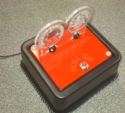
18 Case Assembly You are now ready to assemble the circuit into the case. Your teacher should show you how the cases are made on the vacuum former Choose the colour base you like Fit your circuit into the moulded case Face book Like/Dislike Right or Wrong Heads or Tails
19 Assessment of Making Name Follow Me Stage Description of Task Soldered across? Features of component Your Comment on soldering/ quality / what you understand Target Week to complete Actual Week Completed? 1 Drill 1mm(x32) and 2mm(x10) 1 2 PUSH TO MAKE SWITCH PTM 1 3 Diode D1 Silver band is Cathode 2 4 Resistor 1K R1K Brown, Black, Red, Gold 2 5 Resistor 10K R10K Brown, Black, Orange, Gold 2 6 Capacitor 10uF C10uF Long (+VE) and short leg (-VE) 3 7 Switch SW1 SW1 Yellow multi core wire (30cm) 3 8 PTM Switch PTM Yellow multi core wire (15cm) 3 9 Capacitor 0.01uF (10nF) C0.01uF Orange circular shape. Legs equal length. 104 written on 10 8 Pin Socket 555 Notch with number 8 to top 4 11 Resistor R180 R180 Brown, Grey, Brown, Gold 4 12 Resistor R180 R180 Brown, Grey, Brown, Gold 4 13 LED #1 LED1 Long leg = red, short leg = black 5 14 LED #2 LED2 Long leg = red, short leg = black 5 15 BATTERY CLIP PWR Stitched through strain holes 5 16 INSERT 555 CHIP Pin 1 has a dimple (top left) 6 17 TESTING Battery press switch to flash 6 18 Assemble in case PVC Mould and acrylic case 7 3
WHO ANSWERED FIRST? FIND OUT WITH THIS QUIZ BUZZER KIT
 WHO ANSWERED FIRST? FIND OUT WITH THIS QUIZ BUZZER KIT BUILD INSTRUCTIONS Before you put any components in the board or pick up the soldering iron, just take a look at the Printed Circuit Board (PCB).
step 1 Unpack the lunchbox And check whether you have got all the components~ If you have questions please contact us at: info@unitunlikely.
 step 1 Unpack the lunchbox And check whether you have got all the components~ If you have questions please contact us at: info@unitunlikely.com This part is called the PCB (printed circuit board). All
Martin County Amateur Radio Association. Nightfire Kits 1 LED Torch Kit 270016. Contents. Description
 Nightfire Kits 1 LED Torch Kit 270016 1 Contents Nightfire Kits LED Torch Kit 270016... 1 Description... 1 Safety and Assembly of the kit... 6 Required and Useful Tools... 7 Assembly... 8 Checkout and
DET Practical Electronics (Intermediate 1)
") DET Practical Electronics (Intermediate 1) 731 August 2000 HIGHER STILL DET Practical Electronics (Intermediate 1) Support Materials CONTENTS Section 1 Learning about Resistors Section 2 Learning about
DET Practical Electronics (Intermediate 1) 731 August 2000 HIGHER STILL DET Practical Electronics (Intermediate 1) Support Materials CONTENTS Section 1 Learning about Resistors Section 2 Learning about
Tutorials Drawing a 555 timer circuit
 Step 1 of 10: Introduction This tutorial shows you how to make an electronic circuit using Livewire and PCB Wizard 3. You should follow this tutorial to learn the basic skills you will need to use Livewire
GLOLAB Universal Telephone Hold
 GLOLAB Universal Telephone Hold 1 UNIVERSAL HOLD CIRCUIT If you have touch tone telephone service, you can now put a call on hold from any phone in the house, even from cordless phones and phones without
www.rkeducation.co.uk solutions for teaching and learning
 Teacher Notes Transistor Astable Project Introduction The aim of this 7 week (2hr lessons) project is to design and manufacture an electronic product based on the transistor astable circuit. The project
AXE114S BINARY CLOCK. revolution Revolution Education Ltd. Email: info@rev-ed.co.uk Web: www.rev-ed.co.uk Version 1.1 12/09/08 AXE114.PMD.
 AXE114S BINARY CLOCK Features: The PICAXE binary clock kit tells the time by lighting up blue LEDs in a binary pattern. This is a useful tool for teaching students binary code or simply just confusing/
THE ELECTRONIC DICE. a technology project for secondary education. Name: Class:
 THE ELECTRONIC DICE a technology project for secondary education Name: Class: Many parties were involved in making this lesson / project available for schools: This technology project was originally developed
Electronics and Soldering Notes
 Electronics and Soldering Notes The Tools You ll Need While there are literally one hundred tools for soldering, testing, and fixing electronic circuits, you only need a few to make robot. These tools
BUILDING INSTRUCTIONS
 etap2hw 38 mm I2C to LCD Interface BUILDING INSTRUCTIONS October 2013 P. Verbruggen Rev 1.01 15-Oct-13 Page 1 Table of Contents Chapter 1 General Information 1.1 ESD Precautions 1.2 Further Supplies 1.3
Knight Audio Technologies Ltd. Deacy - Style Amplifier Kit Build Instructions
 Knight Audio Technologies Ltd Deacy - Style Amplifier Kit Build Instructions Introduction Firstly, thank you for purchasing this amplifier kit. We have designed this amplifier based on the Mullard 1960
TEACHING RESOURCES SCHEMES OF WORK DEVELOPING A SPECIFICATION COMPONENT FACTSHEETS HOW TO SOLDER GUIDE GET IN TUNE WITH THIS FM RADIO KIT. Version 2.
 TEACHING RESOURCES SCHEMES OF WORK DEVELOPING A SPECIFICATION COMPONENT FACTSHEETS HOW TO SOLDER GUIDE GET IN TUNE WITH THIS FM RADIO KIT Version 2.0 Index of Sheets TEACHING RESOURCES Index of Sheets
Assembly and User Guide
 1 Amp Adjustable Electronic Load 30V Max, 1 Amp, 20 Watts Powered by: 9V Battery Assembly and User Guide Pico Load is a convenient constant current load for testing batteries and power supplies. The digital
Cumbria Designs T-1. SSB/CW Filter kit (4.9152MHz) User Manual
 User Manual") Cumbria Designs T-1 SSB/CW Filter kit (4.9152MHz) User Manual CONTENTS 1 INTRODUCTION 2 2 CIRCUIT DESCRIPTION 2 3 ASSEMBLY 2 4 TESTING 4 The Steading Stainton PENRITH Cumbria CA11 0ES UK 1 Introduction
Cumbria Designs T-1 SSB/CW Filter kit (4.9152MHz) User Manual CONTENTS 1 INTRODUCTION 2 2 CIRCUIT DESCRIPTION 2 3 ASSEMBLY 2 4 TESTING 4 The Steading Stainton PENRITH Cumbria CA11 0ES UK 1 Introduction
Modifying the Yaesu FT-847 External 22.625 MHz Reference Input
 Modifying the Yaesu FT-847 External 22.625 MHz Reference Input David Smith VK3HZ Introduction This document describes the modification of an FT-847 to allow an external 22.625 MHz Reference oscillator
RESISTANCE SUBSTITUTION BOX
 RESISTANCE SUBSTITUTION BOX MODEL RS-400 / K-37 Assembly and Instruction Manual TM Elenco Electronics, Inc. Copyright 1990 Elenco TM Electronics, Inc. Revised 2003 REV-G 753RS400 The Resistance Substitution
Document number RS-PRD-00130 Revision 05 Date 20/10/2009 Page 1/30
 Date 20/10/2009 Page 1/30 1. Purpose This document describes the field replacement of the footscan plate cable for these models: 2m hi-end plate SN 11/5/xxx 2m pro plate SN 7/5/xxx 0.5m 2003 hi-end plate
ECEN 1400, Introduction to Analog and Digital Electronics
 ECEN 1400, Introduction to Analog and Digital Electronics Lab 4: Power supply 1 INTRODUCTION This lab will span two lab periods. In this lab, you will create the power supply that transforms the AC wall
POCKET AUDIO GENERATOR K8065
 POCKET AUDIO GENERATOR K8065 Great little gadget for service repair, testing, education, etc... ILLUSTRATED ASSEMBLY MANUAL H8065IP-1 VELLEMAN NV Legen Heirweg 33 9890 Gavere Belgium Europe www.velleman.be
BMD16N-SD. version 1.2
 BMD16NSD version 1.2 Feedback decoder with 16 contacts with integrated current detection for the S88bus Compatible with a.o. Märklin Digital, Uhlenbrock Intellibox, Fleischmann TwinCenter and LDT HSI88
BURGLAR ALARM KIT MODEL K-23. Assembly and Instruction Manual ELENCO
 BURGLAR ALARM KIT MODEL K-23 Assembly and Instruction Manual ELENCO Copyright 2013, 1989 ELENCO Electronics, Inc. Revised 2011 REV-Q 753223 No part of this book shall be reproduced by any means; electronic,
PolyBot Board. User's Guide V1.11 9/20/08
 PolyBot Board User's Guide V1.11 9/20/08 PolyBot Board v1.1 16 pin LCD connector 4-pin SPI port (can be used as digital I/O) 10 Analog inputs +5V GND GND JP_PWR 3-pin logic power jumper (short top 2 pins
TEECES DOME LIGHTING SYSTEMS
 This lighting system was designed by John V (Teeces) to be a simple, customizable, expandable and affordable solution for dome lighting. An Arduino micro-controller is used to tell LED driver chips which
DC Circuits (Combination of resistances)
") Name: Partner: Partner: Partner: DC Circuits (Combination of resistances) EQUIPMENT NEEDED: Circuits Experiment Board One Dcell Battery Wire leads Multimeter 100, 330, 1k resistors Purpose The purpose
Name: Partner: Partner: Partner: DC Circuits (Combination of resistances) EQUIPMENT NEEDED: Circuits Experiment Board One Dcell Battery Wire leads Multimeter 100, 330, 1k resistors Purpose The purpose
Joule Thief 3.0 Kit. June 2012, Rev 1 1 http://www.easternvoltageresearch.com Joule Thief 3.0
 Kit Instruction Manual Eastern Voltage Research, LLC June 2012, Rev 1 1 http://www.easternvoltageresearch.com HIGH BRIGHTNESS LED THIS KIT USES A 1W CREE, HIGH BRIGHTNESS LED. DO NOT STARE AT THIS (OR
The Radio-Kits Digital SWR meter kit Construction and user manual
 The Radio-Kits Digital SWR meter kit Construction and user manual Author - Steve Drury G6ALU List of contents Section Page no. 1. Features and specifications 2 2. Introduction 2. Construction 4. General
K8025 VIDEO PATTERN GENERATOR. Check the picture quality of your monitor or TV, ideal for adjustment or troubleshooting.
 K8025 ILLUSTRATED ASSEMBLY MANUAL H8025IP 1 VIDEO PATTERN GENERATOR Check the picture quality of your monitor or TV, ideal for adjustment or troubleshooting. Forum Participate our Velleman Projects Forum
The RSGB Centenary Receiver Project Construction Manual
 The RSGB Centenary Receiver Project Construction Manual Page 1 of 12 Introduction This project is intended for those new to radio construction. It is a fairly simple receiver for the 14MHz (20m) amateur
Spreader Light Bulb Replacement Instructions
 Spreader Light Bulb Replacement Instructions IMPORTANT: DISCONNECT LIGHT FROM BATTERY BEFORE PROCEEDING. FAILURE TO DO SO MAY RESULT IN PERSONAL INJURY OR OTHER DAMAGE. Tools Needed You will need the following
Kit 106. 50 Watt Audio Amplifier
 Kit 106 50 Watt Audio Amplifier T his kit is based on an amazing IC amplifier module from ST Electronics, the TDA7294 It is intended for use as a high quality audio class AB amplifier in hi-fi applications
The G-QRP Club. The Limerick Sudden 40m Receiver Kit
 The G-QRP Club The Limerick Sudden 40m Receiver Kit Circuit design George Dobbs G3RJV PCB design Rex Harper W1REX Kit parts spec and purchase Graham Firth G3MFJ Manual G3RJV and G3MFJ soku=j~ó=omnp= 1
The $25 Son of a cheap timer This is not suitable for a beginner. You must have soldering skills in order to build this kit.
 The $25 Son of a cheap timer This is not suitable for a beginner. You must have soldering skills in order to build this kit. Micro Wizard has been manufacturing Pinewood Derby timers for over 10 years.
Electronic Circuit Construction:
 Electronic Circuit Construction: Various methods are used for building electronic circuits. The method that you choose depends on a number of factors, including the resources available to you and whether
DUAL ELECTRONIC DICE K3400
 DUAL ELECTRONIC DICE K3400 Cheating is no longer possible! ILLUSTRATED ASSEMBLY MANUAL H3400IP-1 VELLEMAN NV Legen Heirweg 33 9890 Gavere Belgium Europe www.velleman.be www.velleman-kit.com Features &
revolution Revolution Education Ltd. Email: info@rev-ed.co.uk Web: www.rev-ed.co.uk Vesrion 2.128/08/02 PICLOCK.P65 SELF -ASSEMBL Order Codes:
 PIC IC L -A IC LOCK SELF ELF-A -ASSEMBL SSEMBLY KIT IT IT (V2) Order Codes: CHI008 PIC Lock Self-Assembly Kit 1 2 3 4 5 6 7 8 9 0 # SW + OUT + 6V 0V Ú LK1 LK2 Features 12 key telephone style keypad bicolour
7-SEGMENT DIGITAL CLOCK
 57mm 7-SEGMENT DIGITAL CLOCK Large 57mm clock & temperature display with extra unique feature Total solder points: 263 Difficulty level: beginner 1 2 3 4 5 advanced K8089 ILLUSTRATED ASSEMBLY MANUAL H8089IP-1
Example use of a microcontroller. Revolution Education Ltd. Web: www.picaxe.co.uk
 1 ELECTRONIC DICE What is a microcontroller? A microcontroller is often described as a 'computer-on-a-chip'. It can be used as an electronic brain to control a product, toy or machine. The microcontroller
Functioning. Layout Diagram. Technical Data. Connection Diagram. 2.4.3. Fixing the Battery Clip. 2.4.4. Inserting the Panel for the Slide Switch
 Sales Germany and other EU Countries Naturschutzzentrum Westlicher Hegau Erwin-Dietrich-Str. 3 D-78244 Gottmadingen Phone: 07731/977 103 Fax: 07731/977 104 e-mail: nsz.hegau@bund.net SSF - Bat Detector
Total solder points: 167 Difficulty level: beginner 1 2 3 4 5 advanced DMX CONTROLLED RELAY K8072 ILLUSTRATED ASSEMBLY MANUAL
 Total solder points: 167 Difficulty level: beginner 1 2 3 4 5 advanced DMX CONTROLLED RELAY K8072 Control a relay by means of the wellknown DMX512 protocol. ILLUSTRATED ASSEMBLY MANUAL H8072IP-1 Features
Assembly Notes. Disclaimer:
 Assembly Notes Before you start building your kit, please take time to read the manual in full at least once to enable you to fully understand the procedures and avoid any mistakes. The following notes
GUITAR PREAMPLIFIER WITH HEADPHONE OUTPUT K4102
 H4102IP-1 GUITAR PREAMPLIFIER WITH HEADPHONE OUTPUT K4102 Practice the guitar without disturbing others. Features & Specifications Features: An electric guitar cannot be connected to just any amplifier
Example use of a microcontroller.
 1 SAFETY LIGHT What is a microcontroller? A microcontroller is often described as a 'computer-on-a-chip'. It can be used as an electronic brain to control a product, toy or machine. The microcontroller
Build a Junior Solar Sprint Model Car Kit Materials: 1 PITSCO Ray Catcher Sprint Kit or Solar Made Junior Solar Sprint Kit 1 White Sheet of Plastic
 Build a Junior Solar Sprint Model Car Kit Materials: 1 PITSCO Ray Catcher Sprint Kit or Solar Made Junior Solar Sprint Kit 1 White Sheet of Plastic Coated Paper 2 Balsa Sheets (10-1/2 x4 x3/16 ) 2 Alligator
How To Make A Feedback Decoder For A Model Railroad
 BMD16N version 1.2 Feedback decoder with 16 contacts for the S88-bus Compatible with a.o. Märklin Digital, Uhlenbrock Intellibox, Fleischmann Twin-Center and LDT HSI-88 Compatible with the s88-n standard
INSTRUCTIONS FOR CHAIN LINK INSTALLATION Chain Link fence & Posts Meshdirect.co.uk
 INSTRUCTIONS FOR CHAIN LINK INSTALLATION Chain Link fence & Posts Meshdirect.co.uk This guide explains how to correctly install our chain link fencing and post system. The guide provides details of the
ROTOPOD PERISCOPE LIGHTING KIT (for MCWHLR & Daniel D/Xeno Periscopes)
") ROTOPOD PERISCOPE LIGHTING KIT (for MCWHLR & Daniel D/Xeno Periscopes) 14-APR-2012_rev 1.2 I designed the Periscope Lighting Kit to be as flexible as possible. Every LED is individually controllable. I
ROTOPOD PERISCOPE LIGHTING KIT (for MCWHLR & Daniel D/Xeno Periscopes) 14-APR-2012_rev 1.2 I designed the Periscope Lighting Kit to be as flexible as possible. Every LED is individually controllable. I
MGB Chrome Bumper Conversion
 MGB Chrome Bumper Conversion Installation Instructions For 1974 1/2-1980 MGB This kit requires cutting, welding, and painting. Professional installation recommended. Note: Every MGB body is slightly different
ARDUINO SEVERINO SERIAL SINGLE SIDED VERSION 3 S3v3 (REVISION 2) USER MANUAL
 USER MANUAL") ARDUINO SEVERINO SERIAL SINGLE SIDED VERSION 3 S3v3 (REVISION 2) USER MANUAL X1: DE-9 serial connector Used to connect computer (or other devices) using RS-232 standard. Needs a serial cable, with at least
ARDUINO SEVERINO SERIAL SINGLE SIDED VERSION 3 S3v3 (REVISION 2) USER MANUAL X1: DE-9 serial connector Used to connect computer (or other devices) using RS-232 standard. Needs a serial cable, with at least
Anderson Powerpoles. Powerpole Assembly Instructions for SCOUT, NAVIGATOR AND RANGER ROV s
 Anderson Powerpoles Powerpole Assembly Instructions for SCOUT, NAVIGATOR AND RANGER ROV s Anderson Powerpoles Power Connections NEW in 2016!!! ELEC-010E: Power supply connections will be Red/Black Anderson
Your Multimeter. The Arduino Uno 10/1/2012. Using Your Arduino, Breadboard and Multimeter. EAS 199A Fall 2012. Work in teams of two!
 Using Your Arduino, Breadboard and Multimeter Work in teams of two! EAS 199A Fall 2012 pincer clips good for working with breadboard wiring (push these onto probes) Your Multimeter probes leads Turn knob
INTERNATIONAL ATOMIC ENERGY AGENCY INSTRUMENTATION UNIT SMD (SURFACE MOUNTED DEVICES) REPAIR S. WIERZBINSKI FEBRUARY 1999
 REPAIR S. WIERZBINSKI FEBRUARY 1999") (SURFACE MOUNTED DEVICES) REPAIR S. WIERZBINSKI FEBRUARY 1999 (SURFACE MOUNTED DEVICES) REPAIR 1 TABLE OF CONTENTS PAGE 1. INTRODUCTION 3 2. ADVANTAGES 4 3. LIMITATIONS 4 4. DIALECT 5 5. SIZES AND DIMENSIONS
(SURFACE MOUNTED DEVICES) REPAIR S. WIERZBINSKI FEBRUARY 1999 (SURFACE MOUNTED DEVICES) REPAIR 1 TABLE OF CONTENTS PAGE 1. INTRODUCTION 3 2. ADVANTAGES 4 3. LIMITATIONS 4 4. DIALECT 5 5. SIZES AND DIMENSIONS
Leaving Certificate Technology 20XX / 20XX. Ordinary Level
 Leaving Certificate Technology 20XX / 20XX Ordinary Level Exam Number: The Theme... 1 Analysis, Research and Investigation... 3 Overall Management of Project... 13 Design Ideas & Selection of Optimum
K6002 TEMPERATURE CONTROLLER. Specifications
 Total solder points: 169 + 99 + 67 Difficulty level: beginner 1 2 3 4 5 advanced TEMPERATURE CONTROLLER K6002 Unlike a normal thermostat, this kit has two outputs, one for "high" alarm and one for "low"
K4401 SOUND GENERATOR. them at the touch of a button. Specifications
 SOUND GENERATOR K4401 Sound effects, tunes, sirens... 10 of them at the touch of a button. Specifications Loudspeakers output : 8 ohm/1w Line output : 1VRms. Power supply : 8 10VDC (9v battery). Max. current
Total solder points: 205 Difficulty level: beginner 1 2 3 4 5 advanced UNIVERSAL BATTERY CHARGER / DISCHARGER K7300 ILLUSTRATED ASSEMBLY MANUAL
 Total solder points: 205 Difficulty level: beginner 1 2 3 4 5 advanced UNIVERSAL BATTERY CHARGER / DISCHARGER K7300 Automatic (dis)charging of both NiCd and NiMH batteries. ILLUSTRATED ASSEMBLY MANUAL
Analog control unit for mobile robots
 Analog control unit for mobile robots Soldering kit for experimentation For Fischertechnik robots and others Most diverse functions Requires no programming Patented sensor technology Summary We are pleased
!Operation:!1. Connect an external power source to J1 (+ and - IN terminals). The
. The") The CB500 Electronic Circuit Breaker is an resettable circuit breaker (fuse) that disconnects power when the trip setting is exceeded. There are 4 trip settings that can easily be changed and set during
The CB500 Electronic Circuit Breaker is an resettable circuit breaker (fuse) that disconnects power when the trip setting is exceeded. There are 4 trip settings that can easily be changed and set during
Micrio WS1 Replacement Wind Speed Sensor and WC1 Replacement Wind Compass Sensor for Raymarine ST50 and ST60 Wind Instruments. Rev 4.
 Micrio WS1 Replacement Wind Speed Sensor and WC1 Replacement Wind Compass Sensor for Raymarine ST50 and ST60 Wind Instruments. Rev 4.1 The Micrio WS1 Wind Speed Sensor and WC1 Compass Sensor are direct
Time needed: ~3h for lid replacement only. Add 1h for operation harness in lid and ~2h more for installing drive unit and cable harness in trunk.
 DIY for replacing trunk lid and/or retrofitting electrical operation of trunk lid. This document is meant to be a support and give advice on the procedure but I will take no responsibility for any damage
Fitting a Hornby 4 Function Decoder and a PCB Lighting Board to a Hornby Inter City 125 (HST) The lighting board is made by Black Cat Technology
 The lighting board is made by Black Cat Technology") Fitting a Hornby 4 Function Decoder and a PCB Lighting Board to a Hornby Inter City 125 (HST) The lighting board is made by Black Cat Technology All photographs and text are copyright to myself so please
Fitting a Hornby 4 Function Decoder and a PCB Lighting Board to a Hornby Inter City 125 (HST) The lighting board is made by Black Cat Technology All photographs and text are copyright to myself so please
Total solder points: 129 Difficulty level: beginner 1 2 3 4 5 advanced LIQUID LEVEL CONTROLLER K2639 ILLUSTRATED ASSEMBLY MANUAL H2639IP-1
 Total solder points: 129 Difficulty level: beginner 1 2 3 4 5 advanced LIQUID LEVEL CONTROLLER K2639 Forgotten to turn off the tap, leaking washing machines,... Prevention is better than cure. So use this
Capacitive Touch Sensor Project:
 NOTE: This project does not include a complete parts list. In particular, the IC described here does not come in a dual-inline-package (DIP), and so a gull-wing package has to be soldered to an adaptor
Build Your Own Solar Car Teach build learn renewable Energy! Page 1 of 1
 Solar Car Teach build learn renewable Energy! Page 1 of 1 Background Not only is the sun a source of heat and light, it s a source of electricity too! Solar cells, also called photovoltaic cells, are used
Pocket Tracker Assembly Instructions version 1.05
 Pocket Tracker Assembly Instructions version 1.05 These instructions will aid in the assembly of the Pocket Tracker, which is designed to fit perfectly with its 9-volt battery in an Altoids candy tin.
VOLUME AND TONE CONTROL - PREAMPLIFIER K8084
 H8084IP-1 VOLUME AND TONE CONTROL - PREAMPLIFIER K8084 When using one of our amplifiers (big or small), you always need a volume control and preferably also a tone control Features & specifications When
200W DISCRETE POWER AMPLIFIER K8060
 H8060IP-1 200W DISCRETE POWER AMPLIFIER K8060 Ideal for active speaker system or subwoofer, guitar amp, home theatre systems, instrument amp, etc. Features & Specifications Specifications: Excellent value
www.sebury.com.cn Digital Keypad Use s Manual
 K3 K4 www.sebury.com.cn Digital Keypad Use s Manual Contents Introduction Introduction Specifications Intramural Interface Circuit 3 Mounting 3 Wiring 5 Power UP 7 Engineer Programming Mode 7 The K3/K4
Nixie Clock Universal Kit V1.08. Assembly and Operation. Software Version 6.3 Revision 11. 11. 2012
 Nixie Clock Universal Kit V1.08 Assembly and Operation Software Version 6.3 Revision 11. 11. 2012 This document is copyrighted. No parts of this documentation may be used commercially. Nixie Clock Kit
MAINS VOLTAGE DETECTOR K7101
 With this device wires can be very easily checked for mains voltage. H7101IP-1 MAINS VOLTAGE DETECTOR K7101 VELLEMAN NV Legen Heirweg 33 9890 Gavere Belgium Europe www.velleman.be www.velleman-kit.com
SYMMETRIC 1A POWER SUPPLY K8042
 SYMMETRIC 1A POWER SUPPLY K8042 Low cost universal symmetric power supply ILLUSTRATED ASSEMBLY MANUAL H8042IP-1 Features & Specifications Features low cost universal symmetric power supply just add a suitable
20000068 WIRELESS REMOTE ASSEMBLY, 24VDC, 1 TRANS,1 REC
 20000068 WIRELESS REMOTE ASSEMBLY, 24VDC, 1 TRANS,1 REC Fitment to MP-25 620 CR 4841, Haslet, TX 76052 Ph 817.439.1108 Fax 817.636.5675 www.machine-technologies.com Kit contents 1 Transmitter 2 button,
THE ELECTRONIC DICE. Teacher s manual. a technology project for secondary education
 THE ELECTRONIC DICE Teacher s manual a technology project for secondary education Many parties were involved in making this lesson / project available for schools: This technology project was originally
Guide for Modified Assembly: Lightning McQueen. By: Collin Patterson, University of Delaware. Materials and Tools:
 Guide for Modified Assembly: Lightning McQueen By: Collin Patterson, University of Delaware Materials and Tools: PVC o 40 inches of 1 in diameter PVC o 25 inches of ¾ in PVC o 4 x 1 in elbows o 2 x ¾ in
HAND CRIMP TOOL M22520/2-01
 HAND CRIMP TOOL M22520/2-01 This Hand Crimp Tool has been designed for use with the following Datamate crimp sockets (when used with Positioner T5747): M80-0110001... Large bore crimp socket (22 AWG),
 P105 SINGLE STICK REVERSER PICTURE 1: PCB with headers PICTURE 3: Resistors added PICTURE 5: Add tactile switch (button) PICTURE 7: Fit lead and PIC chip. NOTE! ANTI-STATIC PRECAUTIONS REQUIRED PICTURE
RS232/DB9 An RS232 to TTL Level Converter
 RS232/DB9 An RS232 to TTL Level Converter The RS232/DB9 is designed to convert TTL level signals into RS232 level signals. This cable allows you to connect a TTL level device, such as the serial port on
DIY Y6. Build Manual V.A 2014
 DIY Y6 Build Manual V.A 2014 1 Contents Thanks for purchasing a DIY Y6! These instructions will show you how to assemble a Y6 using the Pixhawk autopilot system and ArduCopter/APM:Copter firmware. If you
EXPRESS PCB TUTORIAL Author: Lee Morey Revised: JE Feb 2015
 EXPRESS PCB TUTORIAL Author: Lee Morey Revised: JE Feb 2015 Getting Started There are several resources for learning how to layout schematics and PCBs. And there are several popular commercial packages.
CM705B - Universal Expander Module CM707B - Plug On Zone Expander Security Systems
 CM705B - Universal Expander Module CM707B - Plug On Zone Expander Security Systems EN Security System CM705B CM705B - Universal Expander Module The CM705B universal expander provides a cost effective way
Assembly Instructions: Shortwave Radio Kit
 Assembly Instructions: Shortwave Radio Kit MTM Scientific, Inc P.O. Box 522 Clinton, MI 49236 U.S.A Introduction Fig 1: The assembled Shortwave Radio Kit The SHORTWAVE RADIO KIT (#SWRAD) from MTM Scientific
EASY START SYSTEM. Toni Clark practical scale GmbH EASY START SYSTEM 1
 1 GB Toni Clark practical scale GmbH 2 2 INSTALLATION: Unplug the connector in the red lead from power coil to spark coil. Push the round plug of the Easy Start into the power coil s red lead connector.
400W MONO/STEREO AMPLIFIER
 400W MONO/STEREO AMPLIFIER Universal, robust and compact are the words to describe this amplifier. Total solder points: 264 Difficulty level: beginner 1 2 3 4 5 advanced K4005B ILLUSTRATED ASSEMBLY MANUAL
How To Power A 12 Volt Relay On A Car Or Truck
 Relay modification for older bikes Please read this in conjunction with the schematics at the end. All the options are shown, but you can opt to do any one or more as you wish. The electrical connections
Odyssey of the Mind Technology Fair. Simple Electronics
 Simple Electronics 1. Terms volts, amps, ohms, watts, positive, negative, AC, DC 2. Matching voltages a. Series vs. parallel 3. Battery capacity 4. Simple electronic circuit light bulb 5. Chose the right
Total solder points: 57 Difficulty level: beginner 1 2 3 4 5 advanced 3 TO 30VDC / 3A POWER SUPPLY K7203 ILLUSTRATED ASSEMBLY MANUAL H7203IP-1
 Total solder points: 57 Difficulty level: beginner 1 2 3 4 5 advanced 3 TO 30VDC / 3A POWER SUPPLY K7203 A power supply for all our kits, based on a stabilised DC voltage of 30V. ILLUSTRATED ASSEMBLY MANUAL
WIRE, TERMINAL AND CONNECTOR REPAIR CONDUCTORS
 CONDUCTORS Conductors are needed to complete the path for electrical current to flow from the power source to the working devices and back to the power source. Special wiring is needed for battery cables
P C B Wiz a r d 3 T u t o r i a l 3 Drawing a test probe circuit
 Step 1 of 10: Introduction This tutorial shows you how to design and make a test probe with PCB Wizard. You should follow this tutorial to learn the basic skills you will need to use PCB Wizard effectively.
No Rainfall Data is Collected
 No Rainfall Data is Collected There are a number of issues that can cause the system to not collect rainfall data, from clogged collectors to hardware failure or improper part replacement. The most common
Objectives: Part 1: Build a simple power supply. CS99S Laboratory 1
 CS99S Laboratory 1 Objectives: 1. Become familiar with the breadboard 2. Build a logic power supply 3. Use switches to make 1s and 0s 4. Use LEDs to observe 1s and 0s 5. Make a simple oscillator 6. Use
Robot Board Sub-System Testing. Abstract. Introduction and Theory. Equipment. Procedures. EE 101 Spring 2006 Date: Lab Section # Lab #6
 EE 101 Spring 2006 Date: Lab Section # Lab #6 Name: Robot Board Sub-System Testing Partner: No Lab partners this time! Abstract The ECEbot robots have a printed circuit board (PCB) containing most of the
GE Wireless Devices Battery Replacement
 60-506-319.5 Crystal Smoke Detector Two 9V Duracell 9V 1. Twist counter-clockwise until detector become loose from base. 2. Replace batteries observing correct polarity. 3. Replace detector by twisting
DIY QUAD. Build Manual V.A 2014
 DIY QUAD Build Manual V.A 2014 1 Contents Thanks for purchasing a DIY Quad! These instructions will show you how to assemble a Quad using the Pixhawk autopilot system and ArduCopter/APM:Copter firmware.
Bill Conkling July 2012
 Bill Conkling July 2012 Introduction: For any ham, there are moments that are priceless, like snagging that elusive rare DX station on a deserted island that hasn t been activated in 52 years. And certainly,
Exciting new fashionable design... POSEIDON REEF BRACELET INSTRUCTION GUIDE
 Exciting new fashionable design... POSEIDON REEF BRACELET INSTRUCTION GUIDE Stringing POSEIDON REEF BRACELET SWAROVSKI ELEMENTS Article Product Group Article No. Amount Size Color Color Code Fancy Stones
PARTS & INSTALLATION INSTRUCTIONS MEYER SNOW PLOW LIGHTS
 Form 1-696 R1 January, 2003 PARTS & INSTALLATION INSTRUCTIONS MEYER SNOW PLOW LIGHTS PARTS LIST ITEM PART NO. QTY. DESCRIPTION 07033 1 SNOW PLOW LIGHT CARTON 1 07034 1 Snow Plow Light, Pass. Side (No Hardware)
http://waterheatertimer.org/troubleshoot-rheem-tankless-water-heater.html
 http://waterheatertimer.org/troubleshoot-rheem-tankless-water-heater.html TECHNICAL SERVICE DEPARTMENT Removal, Cleaning, & Reinstallation of the Burner Assembly For models 74 & GT199 Required tools -
Wood Technology Electronics
 Wood Technology Electronics It is not necessary to carry out all the activities contained in this unit. Please see Teachers Notes for explanations, additional activities, and tips and suggestions. Theme
1218-75 Watt Audiophile Audio Amplifier
 Description Quasar kit No.1218 is part of a new line of constructions which combined form a full stereo system. The line consists of the following KITS Quasar kit No.1214 6 inputs stereo selector Quasar