Nixie Clock Universal Kit V1.08. Assembly and Operation. Software Version 6.3 Revision
|
|
|
- Brittney Flynn
- 9 years ago
- Views:
Transcription
1 Nixie Clock Universal Kit V1.08 Assembly and Operation Software Version 6.3 Revision This document is copyrighted. No parts of this documentation may be used commercially. Nixie Clock Kit V1.08 Assembly and Operation 1

2 CONTENTS 1 INTRODUCTION SAFETY AND LEGAL WARNINGS W HAT YOU NEED TOOLS PARTS PARTS LISTS CLOCK PCB V TUBE PCB V1.08A, V1.08D, V1.08E AND V1.08F RESISTOR VALUES ASSEMBLING THE CLOCK PCB SOLDER THE COMPONENTS Diodes and Coil IC Sockets and IC Transistors Resistors Trimmer Resistor R Small Capacitors Switches LEDs Solder the regulator Cool Nixie Converter Module Solder the rest of the parts ASSEMBLING THE TUBE PCBS Tube PCB V1.08a CONNECTING A DCF77 RECEIVER SOFTWARE OPERATION CL OCK FEATURES VERSION POWER UP SEQUENCE MANUAL T IME S ETTING MANUAL BRIGHTNESS CO NTROL /24 HOUR MODE S ELECTION / DATE FORMAT SETTING D CF77 INDICATOR LEDS TUBE SAVING MODE SWITCH OFF THE TUBES TO INCREASE THEIR LIFETIME SETTING THE NUMBER OF INSTALLED TUBES APPENDIX AUTO DIMMING LDR OPTION Neon indicator bulbs Parts Identification Suppliers Nixie Clock Kit V1.08 Assembly and Operation 2

3 1 Introduction The Nixie Clock Kit v1.08 can be used with only the clock PCB, or different tube PCBs. At the moment we offer tube PCBs V1.08a, V1.08d, V1.08e and V1.08f. The universal clock PCB v1.08 contains all the clock circuitry. It is a multiplexed design which minimizes the parts count and PCB size, allowing the kit to be mounted in a wide variety of enclosures. Tube PCB V1.08a holds different front view nixie tubes like IN 14, IN 8 2, CD 66 etc. Tube PCB V1.08d is used for 6 IN 8 tubes and LED lighting (Blue Dream) Tube PCB 1.08e is used for 6 B5853 nixie tubes and 12 LEDs (Little Blue Something) Tube PCB V1.08f is used for 6 IN 8 2 tubes and LED lighting (Blue Dream IN 8 2) Tube PCB 1.08g is used for 6 IN 12 nixie tubes and 4 neon bulbs The tube sets can be bought at The documentation of the tube pcbs is described in a separate documentation and is available for download. T his manual documents how to: Assemble and adjust the Clock PCB Connect different types of Nixie tubes to the Tube PCB Connect the Clock PCB and Tube PCB together Implement the following options: o DCF77 time receiver module / GPS converter o Neon AM/PM indicator and flashing colons Operate the completed clock This manual does not cover mounting the competed kit in a specific enclosure. That is left up to you, and is part of the fun of building your own Nixie clock. Please take your time while building the clock it will be worth it. Have fun with your new Nixie clock! Nixie Clock Kit V1.08 Assembly and Operation 3
 Tube PCB V1.08f is used for 6 IN 8 2 tubes and LED lighting (Blue Dream IN 8 2) Tube PCB 1.")
4 1.1 Safety and Legal Warnings DANGER: This circuit design includes a switching mode voltage converter which generates 180 VDC. Therefore, assembly should be attempted only by competent qualified personnel experienced in electronics assembly and high voltage safety. Safe assembly and operation of this kit is completely the reader s responsibility. Read instructions: All the safety and operating instructions should be read carefully and completely before the clock is operated. Heed warnings: All warnings on the appliance and in the operating instructions should be adhered to. Retain Instructions: The safety and operating instructions should be retained for future reference. If one of the tubes is broken or damaged, immediately pull the power plug out of the clock and contact the customer support. The tubes are made of glass and are consequently very easy to break. Because of their fragility, it is important that you keep the clock in a safe place free from the possibility of being struck inadvertently. No part of the clock may be swallowed or inserted into body openings. The power supply may not be swallowed or inserted into body openings. No part of the clock or the power supply may be used for other purpose other than described in this user manual. Water and moisture: The clock should be kept in a dry room free from humidity and dust. The clock should not be used near water for example, near a bath tub, washbowl, kitchen sink, laundry tub, in a wet basement, near a swimming pool, in a sauna, etc. In addition the clock should be kept out of direct sunlight and high temperatures. Object and liquid entry: Care should be taken so that the clock does not fall into liquids or have them spilled over the clock. Do not use this appliance for anything other than the intended use as described in the manual. Immediately pull the power plug out of the clock and contact the customer support if the appliance does not appear to operate normally or exhibits a marked change in performance. In this case do not run the clock again! This clock is not a toy! Keep this clock out of the reach of children. Pay attention that this clock shall only be touched by people who have completely read and understood the user manual. IMPORTANT: Please follow the assembly steps with extreme care. Please operate the clock only in an enclosed housing which prevents contact with the dangerous voltages present on both printed circuit boards (PCB). DISCLAIMER: The information in this document is provided strictly 'as is'. It is hereby stated that this kit is to be assembled only by experienced electronics engineers. No troubleshooting information is provided. Readers should not attempt to build this kit and/or design unless they are competent at electronics assembly and understand the dangers of mains voltages. Further, takes no responsibility for any possible personal or property damage. No responsibility is accepted for any damage, injury (however serious) or death. In no event shall be held liable to you or any third parties for any special, punitive, incidental, indirect, consequential, or any other damages resulting from the assembly or use of this kit and/or design. The assembled unit should be properly encased to prevent contact with high voltages. All applicable UL, CCE, VDE and local regulations must be considered. Commercial use of the kit, circuit designs, software or any parts thereof requires express written permission. Nixie Clock Kit v

5 2 What You Need 2.1 Tools 2.2 Parts Soldering iron Tin solder Wire cutter Multimeter See Section (Appendix) on page 20 for suggested suppliers. Required: Nixie tubes Wall wart power supply, 9V AC or DC, ma If you want to derive the clock timing from the 50Hz/60Hz mains frequency, you must use an AC wall wart. If you use a DCF77 module or any 1pps input for clock timing, you can use an AC or DC wall wart. Optional: DCF77 module. LDR See Section 7.1 (Appendix) on page 20 for details. GPS to DCF Decoder Any tools and parts needed for mounting the kit in a specific enclosure are not listed here. Nixie Clock Kit v
 on page 20 for details. GPS to DCF Decoder Any tools and parts needed for mounting the kit in a specific enclosure are not listed here.")
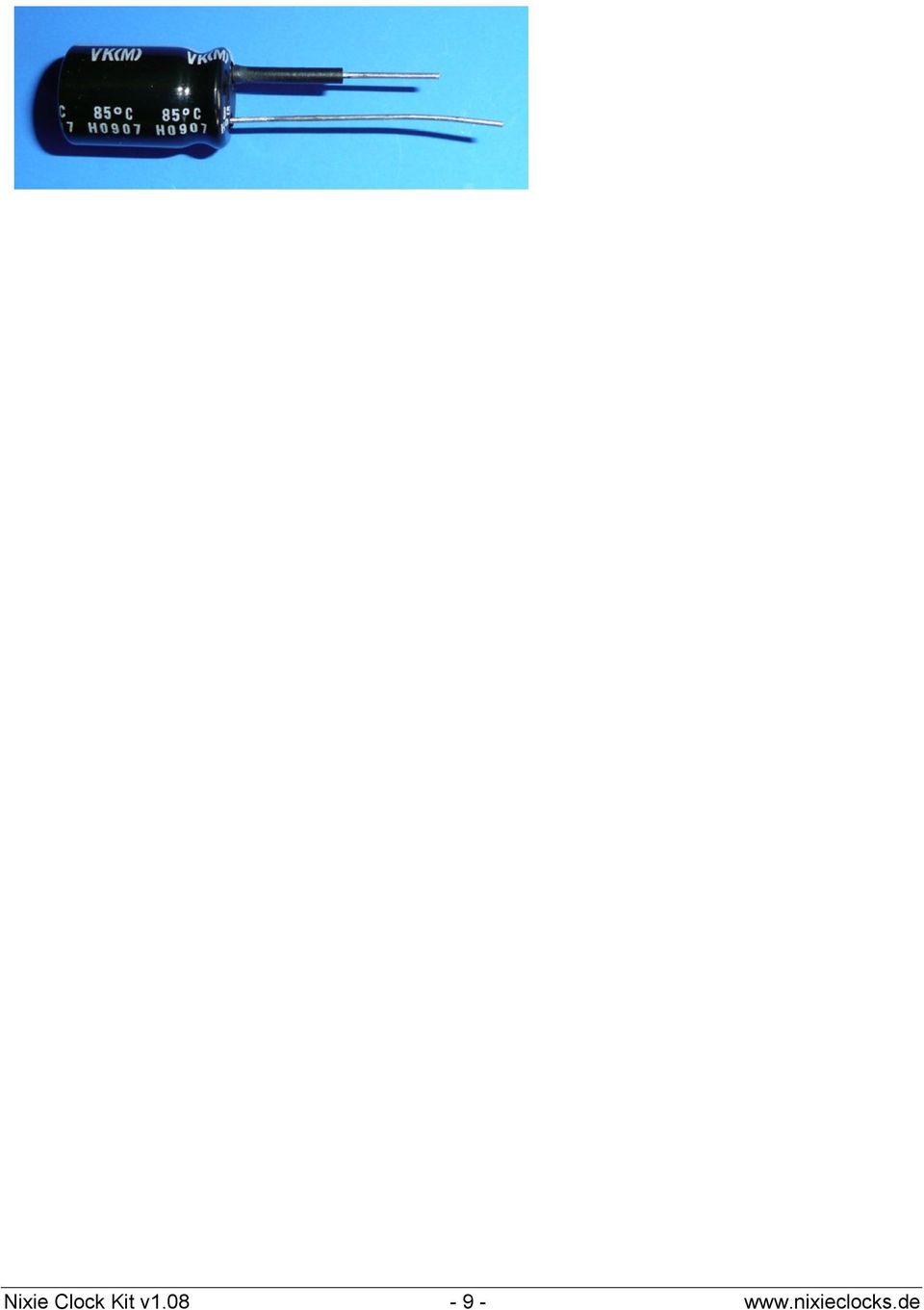
6 3 Parts Lists 3.1 Clock PCB V1.08 Part Part Number Installed Capacitors Capacitor 1000uF/16 25V C3 Capacitor 4,7 uf /250V LoESR C4 Tantal Capacitor 1uF 10uF /16 63V C10 Capacitor 2,2 nf (222) C14 Capacitor 47 pf C13 Capacitor 22 nf (223) C5, C7, C9, C12 Capacitor 22pF C30, C31 Resistors Resistor 100 KΩ R1, R3, R5 Resistor 470 Ω R23, R30, R31, R32 Resistor 1 KΩ R16, R17, R19, R27 Resistor 470 KΩ R2, R4, R6 Resistor 220 KΩ R7 Resistor 10 KΩ * please see 3.2 R18, R26 please se e 3.2 Resistor 33 KΩ R14, R20, R21, R22, R25, R33 Trimmer 1 KΩ R24 Sockets 16 pin socket for driver Socket for IC3 and IC4 28 pin socket for PIC Socket for IC1 Diodes Diode 1N 4001 D1, D2, D3, D4 Diode BYV95C or UF4004 D5 LED dual color D30 LED red D31 Diode Zener ZF 5,6 D9 Transistors Transistor MPSA 92 Q1, Q2, Q3 Transistor MPSA 42 Q4, Q5, Q6, Q8 Transistor FET IRF 730 Q7 Integrated circuits Voltage regulator µa 7805 or cool nixie converter (seen description) PIC processor 16F876 IC1 Driver IC (KM ) IC3, IC4 Timing circuit NE 555 DIP IC5 Other parts Xtal 4 MHZ small version X1 Coil 100µH L1 Switch to set the clock (see description) S1, S2 HEBW 21 Pin diameter 2,1mm (see description) Power Supply socket Shrinking tube for C3 Adhesive pads for IRF730 and Cool nixie converter Pin connector 3 pins J3 Pin connector 20 pins J4 Screws M3x5 H1 H3 Distance holders 12 mm H1 H3 Distance holders 5 mm H1 H3 Micro solder socket for pin connector 3 pins J3 Micro solder socket for pin connector 20 pins J4, J5 PCB version 1.08 Clock Circuit board IC2 Nixie Clock Kit v

7 3.2 Tube PCB V1.08a, V1.08d, V1.08e and V1.08f resistor values The value of the anode resistors on the tube PCB depends on the type of tubes used. 10k resistors work fine with almost all tubes. This is why they are always included in the every kit. The tube PCBs will be delivered with the correct resistors values. So it can be that you have 6 resistors (10K) that you will not use. 4 Assembling the Clock PCB 4.1 Solder the Components IMPORTANT: Solder all the parts according to the partlist and the print on the PCB but do not solder the following parts now: C3, C4, C10, C11 (is not used), C13, C14, IC2, J3, J4, Q7, R19, R25, R26, X1, D30, D31. The parts R19, R25, R26 and C13 are mounted from the solder side of the PCB!! All parts are bold printed in the partlist! Diodes and Coil Solder the diodes D1, D2, D3, D4, D5 und D9 and the Coil L1. All diodes are directional, and have a band marking on one end. Match the band on each diode with the band on the PCB. The coil can be soldered in either direction IC Sockets and IC5 Solder the 3 sockets for the ICs. Be very careful to mount the sockets in the correct orientation. There is a notch on one end of each socket, and the PCB is printed with matching notches. No socket is provided for IC5 (555). It is more effective without a socket, and should be soldered directly to the PCB. It has a notch on one end, or a dot which marks pin 1. The end with the pin 1 dot goes on the same side as the notch printed on the PCB, near the coil. Figure 1 The IC Sockets Transistors Solder the transistors Q1, Q2, Q3, Q4, Q5, Q6 and Q8. Watch out for the orientation on the PCB, and match the flat side of each transistor with the flat side printed on the PCB Resistors Figure 2 Proper transistor mounting See Section (Appendix) for help identifying each resistor. The resistors should be mounted standing up. Figure 3 Detail view of some resistors Nixie Clock Kit v
, C13, C14, IC2,")
8 4.1.5 Trimmer Resistor R24 Solder the trimmer resistor and adjust it to mid position. The trimmer will be used later on to adjust the tube voltage to 170V 180V DC. Attention: Make sure that the metal part of the IRF 730 does not touch the trimmer. Figure 4 Trimmer Resistor R24 and blue trimmer Small Capacitors Switches Figure 5 capacitors TIP: These capacitors are not polarized and can be mounted either way, but for easier identification after the kit is completed, mount them with the markings visible whenever possible. Solder the switches firmly against the PCB. If you plan to mount these (or other) switches elsewhere in your housing, you can connect them to the PCB with wires soldered into the holes meant for the switches. If you use our black brilliance case, do not solder the switches now! Figure 6 Switches for setting the time, dimming and other functions LEDs If you use the black brilliance case do not solder the LEDs to the board. You will not be able to see them. If you want to use them, wire them, drill 2 holes to the back of the case, where the LEDS can be fixed. Nixie Clock Kit v

9 When the clock is in DCF77 mode (See Section 6), the LED s indicate DCF77 signal quality and status. Otherwise, they function as AM/PM indicator and blinking colons. If you will not use a DCF77 module (i.e. you are outside Europe) and you also do not want colons or an AM/PM indicator on your clock, they you do not need to install the LEDs at all. The LEDs are polarized and must be mounted in the correct orientation. This is especially important with the dual color LED D30. If it is mounted backwards, the DFF77 signal indicator will show the wrong color, confusing the user. See Figure 7 and Figure 8 for correct mounting. Figure 7 LED D31 DCF77 status or AM/PM Figure 8 Dual Color LED D30 DCF77 signal quality or blinking colons and status LED For DFC77 mode, be careful to mount the LEDs at the correct height from the PCB to be visible in the enclosure you plan to use. For an AM/PM indicator and blinking colons, use wires to attach your enclosure mounted LEDs to the PCB holes for D30 and D31. For the colons, use regular 2 wire LEDs (not the dual color LED supplied) and wire them to two of the three D30 PCB holes connect to one side for a 1Hz blink rate, or the other side for a.5hz blink rate. If you would like to use Neon bulbs instead of LEDs. Having soldered all the parts (but not C3, C4, C10, C11, C13, C14, IC2, J1, J3, J4, Q7, R19, R25, R26, X1, D30, D31) Your PCB should look like this: If you use the Black Brilliance Case, do not solder SW1, SW2 and the power supply socket your PCB should look like this: Nixie Clock Kit v

10 If you use the Black Brilliance Case solder S1 and S2. The switches come together with the case kit. Solder the Xtal and make sure that it does not touch the PCB. It should be away 1mm from the PCB! Bend the legs of C4 and solder it according to the picture. Shrink the 11 mm shrinking tube over the minus leg of C3: Nixie Clock Kit v

11 Nixie Clock Kit v
12 Bend the legs of C3 and solder it as shown in the following pictures. Even if no power supply socket is soldered in, C3 must be soldered like this: Solder the regulator 7805 If you use the Cool nixie converter module, skip this passage. We highly recommend the cool nixie converter whenever you use LEDs, GPS or DCF with your clock kit or if you use a housing such as the black brilliance case!! Bend the regulator as shown in the picture and solder it into the PCB: Cool Nixie Converter Module Carefully bend the legs of the Cool Nixie Converter Module straight: Before: After: Stick the round adhesive pad to the Cool Nixie Converter Module: Stick the Cool Nixie Converter Module to the PCB as shown here and solder it from the top: Nixie Clock Kit v

13 Solder the rest of the parts Solder C14 ( 222 ) as shown: Bend Q7 (IRF 730) as shown: Place IRF 730 (Q7) to the PCB as shown and solder it: Stick the adhesive pad 10x15 mm to Q7: Nixie Clock Kit v

14 Solder C10: Make sure that the plus connector points to the right as shown in the picture! If you use a DCF receiver or the GPS to DCF converter solder a 3 pin connector (not included) as shown in the picture: If you use the Black Brilliance Case solder 2 red wires (50mm) to the power supply pins on the PCB: Cut all wires on the PCB short to about 0,8mm 1mm. Use a good quality pliers for this! The following parts are mounted from the solder side of the PCB!! Be very careful when soldering them. Nixie Clock Kit v

15 Solder R19 and C13 flat to the PCB as shown. R19 and C13 are connected. Do not stick the wires through the holes, but flat to the solder pads as shown: Solder R25 flat to the PCB as shown. Do not stick the pins through the hole, but solder them flat to the solder pads: Nixie Clock Kit v

16 Solder R26 flat to the PCB as shown. Do not stick the pins through the hole, but solder them flat to the solder pads: Screw the 5mm distance holders through the top of the PCB and connect them with the 12 mm distance holders: Insert the pin rows to the PCB from the top, angle them correctly and solder them from the bottom Attention: The thin ends face upwards!! Nixie Clock Kit v

17 If you use the LED Switch Option in the Black Brilliance Case, solder a 150 mm long red wire as shown in the picture below. You can switch off the LEDs with this option Please check your work carefully!! Nixie Clock Kit v

18 4.2 Assembling the tube PCBs Tube PCB V1.08a Figure 9 IN 14 tubes come with long wires Figure 10 Cut the wires short to facilitate placement on the PCB Figure 11 Bottom view of IN 14 and IN 8 2 Bend the wires of the IN 14 left and right to the anode and cut them. Cut DP on IN 8 2 tube. Figure 12 Place the anode in the anode hole in the PCB. Figure 13 Bottom view of the tube PCB Do not solder the tubes too close to the PCB. Be careful to leave enough lead length to permit bending the leads, if it s necessary to straighten the tubes, and to allow the tubes to protrude enough to be fully visible in whatever enclosure you choose. If you use other tubes via a cable connection, connect the cathodes according to the tube s pin layout. In this manner, it is possible to mount virtually all Nixie tubes to this clock board. Nixie Clock Kit v

19 5 Connecting a DCF77 Receiver The description of the DCF module will be found in a separate documentation. 6 Software Operation 6.1 Clock Features version 6.3 NEW: Slot machine effect for cathode poisoning prevention. We have implemented a 12/24 hr mode, a date format setting from EU date format to US date format, a tube saving routine, a tubes off level in the clock s software. The DCF77 mode is showing DATE and MONTH and YEAR, if in 6 digit mode. If in 4 digit mode the DATE and MONTH are shown, not the year. Every minute when the seconds go from 50 to 55, the date is shown. If no valid DCF77 string has been received after a 23:59 to 00:00 change, the date will not been shown, until new valid string has been received. In the two digits modes, no date will be shown no matter what, sorry. But DCF77 mode is still useful /possible to set the clock. If you don t want the date to be shown in DCF77 mode, please connect a short circuit in the DCF/programming connector J1 from pin 2 and 4 that is RB7 from PIC to ground. 6.2 Power Up Sequence At power up the software version 63 flashes on the HOURS tubes 20 times. The other tubes remain blank. During this time, the clock is looking for a DCF77 signal pulse. This delay has been implemented because DCF77 modules typically take 8 10 seconds to wake up. If there is no DCF77 module attached, this delay can by skipped by pressing the SET button. The clock performs a display test by flashing a sequence of digits on all the tubes for about one second. DCF77 Module not detected: The clock measures the mains frequency for 1 second, then displays it on the MINUTES tubes, along with the software version on the HOURS tubes (such as ). The mains frequency changes slightly throughout the day (slower during the day, faster at night), but always averages exactly 50 or 60 Hz long term. Therefore the measured frequency is typically 49/50/51 Hz or 59/60/61 Hz. However, as long as the frequency is within +/ 5 Hz of 50 or 60 Hz, the clock will go into either 50 or 60 Hz mode and it will be very accurate over a long period of time. If the clock detects a 1 Hz signal instead, such as from a GPS module, it will go into 1 Hz mode. The clock enters normal mode and begins counting the time, starting at DCF77 Module detected: The blinking 63 in the start up shows the version. It will take up to 20 blinks while searching for a DCF77 input. If a DCF input signal is found, the blink sequence is dropped and DCF77 mode is entered directly without further delays! If no DCF module is found, the 20 pulses are shown, so that even slow DCF77 receiver units can be used also. If still no DCF module found after all 20 pulses, the input frequency counter is started and the result is shown in the minutes field. The clock enters normal mode and displays the received time. This might look like 00:00:00. It continues receiving the DCF77 signal and updating the display. or If the DCF77 signal is of poor quality, all the tubes are turned off after 3 minutes and the clock continues looking for a good DCF77 signal. As soon as it receives a good signal, the tubes are turned on and the received time is displayed. If the tubes remain off for a long time, you can manually set the time as described in section 7.3 below. The clock will continue looking for a good DCF77 signal and as soon as it receives one it will replace the manually set time with the exact time as received from DCF77. See Section 6.6 for information on the DCF77 status LED Nixie Clock Kit v

20 indicators. 6.3 M anual Time Setting From normal mode: Press the SET button to enter HOURS set mode. While in set mode, the SECONDS are reset to 00 and are blanked. The HOURS light up bright, since they are being set, and the MINUTES are dimmed. Press the UP/DIM button repeatedly until the correct HOURS are shown. TIP: To switch between 12 hour and 24 hour mode while setting the HOURS, press and hold the UP/DIM button for 3 seconds until all the digits blink momentarily. Press the SET button again to switch to MINUTES set mode. Now the HOURS are dimmed, and the MINUTES are bright. Press the UP/DIM button repeatedly until t he correct MINUTES are shown. Press the SET button again to exit set mode. The SECONDS re appear and begin incrementing from Manual Brightness Control While in normal mode, press the UP/DIM button repeatedly to rotate through the 4 brightness levels. The OFF Level switches the tubes off but the clock still works. Maximum brightness is the default level at powerup. Note that the eye catching fade effect during digit transitions is only on the highest brightness level. In the 3 lower brightness levels, the digits change instantly. Remember that manual brightness setting is deactivated if the LDR feature has been installed (see Section 7.1) /24 Hour Mode Selection / date format setting To switch between 12 hour and 24 hour mode, while in regular mode, press and hold the UP/DIM button for 2 3 seconds until all the digits blink twice quickly. If there is no 12/14 hour indicator LED installed, there may not be any immediate change in the displayed time. The clock will remember the 12/24 hour mode setting even if the clock is turned off. To select the date format you can choose between EU standard DD:MM:YY and US standard MM:DD:YY. Press the DIMM button for 6 seconds and the date format has been changed to US standard (MM:DD:YY) or vice versa. The tubes will blink twice slowly if the change has been made. To go back to the previous date setting just repeat the procedure above. The clock will remember the date format setting even if the clock is turned off. 6.6 DCF77 Indicator LEDs During normal operation: If the dual color LED is blinking green, your clock is receiving a good DCF77 signal and is super accurate. Due to the DUO LED, it has never been so easy and fun to receive correct DCF77 signals. The dual color LED is a signal quality meter, indicating how close the DCF77 pulses are to the correct pulse width. It is very fast reacting and updates every second. A correct pulse width is 100ms or 200ms. The LED blinks green if the pulses are within +/ 10ms of the correct pulse, orange if the pulses are within +/ 20ms, and red if the pulses are within + 30ms. If the pulses are more than 40ms away from correct time, the signal will be marked as bad. That means it is actually possible (in theory) to set the clock to the correct time if only red blinks. 6.7 Tube saving mode switch off the tubes to increase their lifetime The current software version can switch off the tubes at a selected time to increase their lifetime and save power. You can decide what time you want to switch the tubes off by connecting different pins from the pic processor to GND. Nixie Clock Kit v

21 Here is an overview of the possible switch off times: 1. no pins connected default mode tubes on all time 2. tubes off from 00:00 to 01:59 Pin 21 (RB0) of pic processor to GND (Pin 8) 3. tubes off from 02:00 to 04:59 Pin 22 (RB1) of pic processor to GND (Pin 8) 4. tubes off from 05:00 to 06:59 Pin 23 (RB2) of pic processor to GND (Pin 8) Example 1: If you want to switch off the tubes from 00:00 to 06:59 then connect pin 21 and pin 22 and pin 23 to GND (pin 8 of the pic processor). Example 2: If you want to switch off the tubes from 02:00 to 06:59 then connect Pin 22 and Pin 23 to GND and you are done. In the following picture the tubes are switched off from 02:00 to 04:59 (see wire from Pin 8 (GND) to Pin 22 (RB1). You can also use switches so it can be changed if you wish. The maximum switch off time goes from 00:00 to 06:59. The tube save mode works in all display modes (2 tubes / 4 tubes / 6 tubes), in DCF77 mode and in 12 / 24 hr mode! The picture shows the PCB from the bottom with the pic processor in the centre. night. This is the off times only at Here is an easy way to make the setting variable. Just use a DIP switch. Solder 4 pins to the PCB to give the total construction more strength. Of course you have to remove some green paint to get to the copper, otherwise the solder will not hold. 6.8 Setting the Number of Installed Tubes The clock software can drive 2, 4 or 6 digit clocks. To change tube operating mode: Press and hold the SET button, then power up the clock. Continue pressing the SET button, and press the UP/DIM button repeatedly to cycle through the 5 display modes. When you have selected the correct mode, release the SET button and this mode will be saved until you choose a different one. The 5 different tubes modes are as follows: Mode 1: is six tubes 2x3 multiplexed mode normal Nixie tubes (default mode) Mode 2: is four tubes 2x2 multiplexed mode using normal Nixie tubes Mode 3: is four tubes using dual anode tubes 1x4 multiplexed mode Mode 4: is two tube non multiplexed mode using normal Nixie tubes Nixie Clock Kit v
22 Mode 5: for two B7971 or ZM1350 special alphanumeric tubes multiplex 1x32 When the correct mode is chosen, the tubes will show 12 or or depending on how many tubes you have used in your clock. 7 Appendix 7.1 Auto Dimming LDR Option The clock can auto dim the tubes in relation to the light in the room, using an LDR and a resistor. This is an optional feature, and the necessary parts are not included in the kit. The life time of a Nixie tube is determined by its light output multiplied by the hours it is lit. Since this kit uses a multiplexed design, Nixie tube brightness is in general lower compared to non multiplexed Nixie clocks, therefore the lifetime is in general 2 3 times longer in this kit. By adding the auto dimming feature, this can be made times longer. If the LDR feature is in use, the push button dim function is disabled Neon indicator bulbs As explained in Section 4.1.8, the two LEDs can be used as an AM/PM indicator and blinking colons. If you would rather use neon bulbs to match the appearance of the Nixie tubes, the following circuit can be used to drive neon bulbs from the LED outputs. These parts are not supplied with the kit Parts Identification Some of the supplied parts may have alternate markings, as shown here: Diode BYV 95 = FR205 DC Transistor MPSA 92 = KSP MPSA 42 = CMPS A42 Driver ICs = KM155 Capacitors 22 nf = nf = Suppliers Nixie Tubes Dieter Wächter neon bulbs, DCF77 at is a reputable supplier of Nixies. Wall Wart power supply A variety of wall warts from various vendors will work, Radio Shack catalogue number is ideal for the Nixie clock. It is available in their USA retail stores and at You must use an AC wall wart if you use normal clock mode and no DCF77 input. If you are not sure what power supply you should buy, please ask us. We will be happy to help you. Nixie Clock Kit v
ECEN 1400, Introduction to Analog and Digital Electronics
 ECEN 1400, Introduction to Analog and Digital Electronics Lab 4: Power supply 1 INTRODUCTION This lab will span two lab periods. In this lab, you will create the power supply that transforms the AC wall
K8025 VIDEO PATTERN GENERATOR. Check the picture quality of your monitor or TV, ideal for adjustment or troubleshooting.
 K8025 ILLUSTRATED ASSEMBLY MANUAL H8025IP 1 VIDEO PATTERN GENERATOR Check the picture quality of your monitor or TV, ideal for adjustment or troubleshooting. Forum Participate our Velleman Projects Forum
POCKET AUDIO GENERATOR K8065
 POCKET AUDIO GENERATOR K8065 Great little gadget for service repair, testing, education, etc... ILLUSTRATED ASSEMBLY MANUAL H8065IP-1 VELLEMAN NV Legen Heirweg 33 9890 Gavere Belgium Europe www.velleman.be
7-SEGMENT DIGITAL CLOCK
 57mm 7-SEGMENT DIGITAL CLOCK Large 57mm clock & temperature display with extra unique feature Total solder points: 263 Difficulty level: beginner 1 2 3 4 5 advanced K8089 ILLUSTRATED ASSEMBLY MANUAL H8089IP-1
Neonixie 6 Digit Nixie Clock Controller Introduction and Assembly
 Neonixie 6 Digit Nixie Clock Controller Introduction and Assembly Thank you for purchasing our 6 Digit Nixie Clock Controller. Our clock controller is user friendly and has many of the features most requested
K6002 TEMPERATURE CONTROLLER. Specifications
 Total solder points: 169 + 99 + 67 Difficulty level: beginner 1 2 3 4 5 advanced TEMPERATURE CONTROLLER K6002 Unlike a normal thermostat, this kit has two outputs, one for "high" alarm and one for "low"
Total solder points: 57 Difficulty level: beginner 1 2 3 4 5 advanced 3 TO 30VDC / 3A POWER SUPPLY K7203 ILLUSTRATED ASSEMBLY MANUAL H7203IP-1
 Total solder points: 57 Difficulty level: beginner 1 2 3 4 5 advanced 3 TO 30VDC / 3A POWER SUPPLY K7203 A power supply for all our kits, based on a stabilised DC voltage of 30V. ILLUSTRATED ASSEMBLY MANUAL
GLOLAB Universal Telephone Hold
 GLOLAB Universal Telephone Hold 1 UNIVERSAL HOLD CIRCUIT If you have touch tone telephone service, you can now put a call on hold from any phone in the house, even from cordless phones and phones without
Total solder points: 205 Difficulty level: beginner 1 2 3 4 5 advanced UNIVERSAL BATTERY CHARGER / DISCHARGER K7300 ILLUSTRATED ASSEMBLY MANUAL
 Total solder points: 205 Difficulty level: beginner 1 2 3 4 5 advanced UNIVERSAL BATTERY CHARGER / DISCHARGER K7300 Automatic (dis)charging of both NiCd and NiMH batteries. ILLUSTRATED ASSEMBLY MANUAL
AXE114S BINARY CLOCK. revolution Revolution Education Ltd. Email: [email protected] Web: www.rev-ed.co.uk Version 1.1 12/09/08 AXE114.PMD.
 AXE114S BINARY CLOCK Features: The PICAXE binary clock kit tells the time by lighting up blue LEDs in a binary pattern. This is a useful tool for teaching students binary code or simply just confusing/
Total solder points: 167 Difficulty level: beginner 1 2 3 4 5 advanced DMX CONTROLLED RELAY K8072 ILLUSTRATED ASSEMBLY MANUAL
 Total solder points: 167 Difficulty level: beginner 1 2 3 4 5 advanced DMX CONTROLLED RELAY K8072 Control a relay by means of the wellknown DMX512 protocol. ILLUSTRATED ASSEMBLY MANUAL H8072IP-1 Features
!Operation:!1. Connect an external power source to J1 (+ and - IN terminals). The
. The") The CB500 Electronic Circuit Breaker is an resettable circuit breaker (fuse) that disconnects power when the trip setting is exceeded. There are 4 trip settings that can easily be changed and set during
The CB500 Electronic Circuit Breaker is an resettable circuit breaker (fuse) that disconnects power when the trip setting is exceeded. There are 4 trip settings that can easily be changed and set during
Total solder points: 115 Difficulty level: beginner 1 2 3 4 5 advanced 4 CHANNEL RUNNING LIGHT K8032 ILLUSTRATED ASSEMBLY MANUAL
 Total solder points: 115 Difficulty level: beginner 1 2 3 4 5 advanced 4 CHANNEL RUNNING LIGHT K8032 Ideal for creating disco light effects, light speed adjustable. Suited for inductive loads. ILLUSTRATED
WHO ANSWERED FIRST? FIND OUT WITH THIS QUIZ BUZZER KIT
 WHO ANSWERED FIRST? FIND OUT WITH THIS QUIZ BUZZER KIT BUILD INSTRUCTIONS Before you put any components in the board or pick up the soldering iron, just take a look at the Printed Circuit Board (PCB).
Build A Video Switcher. Reprinted with permission from Electronics Now Magazine September 1997 issue
 Build A Video Switcher Reprinted with permission from Electronics Now Magazine September 1997 issue Copyright Gernsback Publications, Inc.,1997 BUILD A VIDEO SWITCHER FRANK MONTEGARI Watch several cameras
Electronics and Soldering Notes
 Electronics and Soldering Notes The Tools You ll Need While there are literally one hundred tools for soldering, testing, and fixing electronic circuits, you only need a few to make robot. These tools
PolyBot Board. User's Guide V1.11 9/20/08
 PolyBot Board User's Guide V1.11 9/20/08 PolyBot Board v1.1 16 pin LCD connector 4-pin SPI port (can be used as digital I/O) 10 Analog inputs +5V GND GND JP_PWR 3-pin logic power jumper (short top 2 pins
Assembly and User Guide
 1 Amp Adjustable Electronic Load 30V Max, 1 Amp, 20 Watts Powered by: 9V Battery Assembly and User Guide Pico Load is a convenient constant current load for testing batteries and power supplies. The digital
Joule Thief 3.0 Kit. June 2012, Rev 1 1 http://www.easternvoltageresearch.com Joule Thief 3.0
 Kit Instruction Manual Eastern Voltage Research, LLC June 2012, Rev 1 1 http://www.easternvoltageresearch.com HIGH BRIGHTNESS LED THIS KIT USES A 1W CREE, HIGH BRIGHTNESS LED. DO NOT STARE AT THIS (OR
Total solder points: 147 Difficulty level: beginner 1 2 3 4 5 advanced VIDEO SIGNAL CLEANER K8036 ILLUSTRATED ASSEMBLY MANUAL
 Total solder points: 147 Difficulty level: beginner 1 2 3 4 5 advanced VIDEO SIGNAL CLEANER K8036 Digitally cleans the video signal of unwanted distortions and improves the picture quality. ILLUSTRATED
SYMMETRIC 1A POWER SUPPLY K8042
 SYMMETRIC 1A POWER SUPPLY K8042 Low cost universal symmetric power supply ILLUSTRATED ASSEMBLY MANUAL H8042IP-1 Features & Specifications Features low cost universal symmetric power supply just add a suitable
DUAL ELECTRONIC DICE K3400
 DUAL ELECTRONIC DICE K3400 Cheating is no longer possible! ILLUSTRATED ASSEMBLY MANUAL H3400IP-1 VELLEMAN NV Legen Heirweg 33 9890 Gavere Belgium Europe www.velleman.be www.velleman-kit.com Features &
K8068 BUS DIMMER FOR HOME MODULAR LIGHT SYSTEM ILLUSTRATED ASSEMBLY MANUAL H8068IP-1
 Total solder points: 74 Difficulty level: beginner 1 2 3 4 5 advanced BUS DIMMER FOR HOME MODULAR LIGHT SYSTEM K8068 PLUG - IN module for use with home modular lights system K8006. For electronic transformers!
SYSTEM 4C. C R H Electronics Design
 SYSTEM 4C C R H Electronics Design SYSTEM 4C All in one modular 4 axis CNC drive board By C R Harding Specifications Main PCB & Input PCB Available with up to 4 Axis X, Y, Z, A outputs. Independent 25
MIDECO 64-outputs MIDI note decoder USER MANUAL. Roman Sowa 2012
 MIDECO 64-outputs MIDI note decoder USER MANUAL Roman Sowa 2012 www.midi-hardware.com 1.Overview Thank you for choosing MIDECO as your new MIDI-to-digital converter. This short manual will guide you through
step 1 Unpack the lunchbox And check whether you have got all the components~ If you have questions please contact us at: info@unitunlikely.
 step 1 Unpack the lunchbox And check whether you have got all the components~ If you have questions please contact us at: [email protected] This part is called the PCB (printed circuit board). All
Total solder points: 129 Difficulty level: beginner 1 2 3 4 5 advanced LIQUID LEVEL CONTROLLER K2639 ILLUSTRATED ASSEMBLY MANUAL H2639IP-1
 Total solder points: 129 Difficulty level: beginner 1 2 3 4 5 advanced LIQUID LEVEL CONTROLLER K2639 Forgotten to turn off the tap, leaking washing machines,... Prevention is better than cure. So use this
Electronic Rotary Table Divider V2.1 Construction
 Electronic Rotary Table Divider V2.1 Construction 2006,2013 Steve Ward ([email protected]) Legal: All documents, code, schematics, firmware etc are offered as an aid to the experienced constructor
Glolab Talking Phone Dial Monitor
 Introduction The detects the tones generated when numbers are dialed on your touch tone telephone and speaks the numbers that were dialed. This verifies that you dialed the correct number and is especially
Using and Wiring Light Emitting Diodes (LEDs) for Model Railroads
 for Model Railroads") Using and Wiring Light Emitting Diodes (LEDs) for Model Railroads LEDs have many useful applications in Model railroading, including: Locomotive headlights Rear-end warning lights for cabooses and passenger
Using and Wiring Light Emitting Diodes (LEDs) for Model Railroads LEDs have many useful applications in Model railroading, including: Locomotive headlights Rear-end warning lights for cabooses and passenger
Advanced LED Controller (LED Chaser)
") Advanced LED Controller (LED Chaser) Introduction. Advanced LED controller (also known as LED Chaser) is microcontroller based circuit designed to produce various visual LED light effects by controlling
Advanced LED Controller (LED Chaser) Introduction. Advanced LED controller (also known as LED Chaser) is microcontroller based circuit designed to produce various visual LED light effects by controlling
Kit 106. 50 Watt Audio Amplifier
 Kit 106 50 Watt Audio Amplifier T his kit is based on an amazing IC amplifier module from ST Electronics, the TDA7294 It is intended for use as a high quality audio class AB amplifier in hi-fi applications
AUTOMATIC CALL RECORDER JAMECO PART NO. 2163735
 AUTOMATIC CALL RECORDER JAMECO PART NO. 2163735 Experience Level: Intermediate Time Required: 1-2 Hours This project automatically records phone calls. The program, along with the adapter records each
BUILDING INSTRUCTIONS
 etap2hw 38 mm I2C to LCD Interface BUILDING INSTRUCTIONS October 2013 P. Verbruggen Rev 1.01 15-Oct-13 Page 1 Table of Contents Chapter 1 General Information 1.1 ESD Precautions 1.2 Further Supplies 1.3
DET Practical Electronics (Intermediate 1)
") DET Practical Electronics (Intermediate 1) 731 August 2000 HIGHER STILL DET Practical Electronics (Intermediate 1) Support Materials CONTENTS Section 1 Learning about Resistors Section 2 Learning about
DET Practical Electronics (Intermediate 1) 731 August 2000 HIGHER STILL DET Practical Electronics (Intermediate 1) Support Materials CONTENTS Section 1 Learning about Resistors Section 2 Learning about
400W MONO/STEREO AMPLIFIER
 400W MONO/STEREO AMPLIFIER Universal, robust and compact are the words to describe this amplifier. Total solder points: 264 Difficulty level: beginner 1 2 3 4 5 advanced K4005B ILLUSTRATED ASSEMBLY MANUAL
Total solder points: 248 Difficulty level: beginner 1 2 3 4 5 advanced. 15 Channel infrared receiver K8050 ILLUSTRATED ASSEMBLY MANUAL
 Total solder points: 48 Difficulty level: beginner 4 5 advanced 5 Channel infrared receiver K8050 IR-Remote control transmitters allow you to control 5 opencollector contacts ILLUSTRATED ASSEMBLY MANUAL
RS232/DB9 An RS232 to TTL Level Converter
 RS232/DB9 An RS232 to TTL Level Converter The RS232/DB9 is designed to convert TTL level signals into RS232 level signals. This cable allows you to connect a TTL level device, such as the serial port on
Modifying the Yaesu FT-847 External 22.625 MHz Reference Input
 Modifying the Yaesu FT-847 External 22.625 MHz Reference Input David Smith VK3HZ Introduction This document describes the modification of an FT-847 to allow an external 22.625 MHz Reference oscillator
POINTS POSITION INDICATOR PPI4
 POINTS POSITION INDICATOR PPI4 Advanced PPI with Adjustable Brightness & Simplified Wiring Monitors the brief positive operating voltage across points motors when they are switched Lights a corresponding
VOLUME AND TONE CONTROL - PREAMPLIFIER K8084
 H8084IP-1 VOLUME AND TONE CONTROL - PREAMPLIFIER K8084 When using one of our amplifiers (big or small), you always need a volume control and preferably also a tone control Features & specifications When
GLOLAB Two Wire Stepper Motor Positioner
 Introduction A simple and inexpensive way to remotely rotate a display or object is with a positioner that uses a stepper motor to rotate it. The motor is driven by a circuit mounted near the motor and
AutoRanging Digital MultiMeter
 Owner's Manual AutoRanging Digital MultiMeter Model No. 82139 CAUTION: Read, understand and follow Safety Rules and Operating Instructions in this manual before using this product. Safety Operation Maintenance
K128. USB PICmicro Programmer. DIY Electronics (HK) Ltd PO Box 88458, Sham Shui Po, Hong Kong. http://www.kitsrus.com mailto: peter@kitsrus.
 Ltd PO Box 88458, Sham Shui Po, Hong Kong. http://www.kitsrus.com mailto: peter@kitsrus.") K128 USB PICmicro Programmer DIY Electronics (HK) Ltd PO Box 88458, Sham Shui Po, Hong Kong http://www.kitsrus.com mailto: [email protected] Last Modified March 31 2003 Board Construction The board is
K128 USB PICmicro Programmer DIY Electronics (HK) Ltd PO Box 88458, Sham Shui Po, Hong Kong http://www.kitsrus.com mailto: [email protected] Last Modified March 31 2003 Board Construction The board is
CHAPTER 11: Flip Flops
 CHAPTER 11: Flip Flops In this chapter, you will be building the part of the circuit that controls the command sequencing. The required circuit must operate the counter and the memory chip. When the teach
Controlling a Dot Matrix LED Display with a Microcontroller
 Controlling a Dot Matrix LED Display with a Microcontroller By Matt Stabile and programming will be explained in general terms as well to allow for adaptation to any comparable microcontroller or LED matrix.
Model 201 Wiegand Touchpad Reader Installation Guide
 Model 201 Wiegand Touchpad Reader Installation Guide P/N 460353001C 15AUG11 2011 UTC Fire & Security. All rights reserved. This document may not be copied in whole or in part or otherwise reproduced without
MAINS VOLTAGE DETECTOR K7101
 With this device wires can be very easily checked for mains voltage. H7101IP-1 MAINS VOLTAGE DETECTOR K7101 VELLEMAN NV Legen Heirweg 33 9890 Gavere Belgium Europe www.velleman.be www.velleman-kit.com
Cumbria Designs T-1. SSB/CW Filter kit (4.9152MHz) User Manual
 User Manual") Cumbria Designs T-1 SSB/CW Filter kit (4.9152MHz) User Manual CONTENTS 1 INTRODUCTION 2 2 CIRCUIT DESCRIPTION 2 3 ASSEMBLY 2 4 TESTING 4 The Steading Stainton PENRITH Cumbria CA11 0ES UK 1 Introduction
Cumbria Designs T-1 SSB/CW Filter kit (4.9152MHz) User Manual CONTENTS 1 INTRODUCTION 2 2 CIRCUIT DESCRIPTION 2 3 ASSEMBLY 2 4 TESTING 4 The Steading Stainton PENRITH Cumbria CA11 0ES UK 1 Introduction
200W DISCRETE POWER AMPLIFIER K8060
 H8060IP-1 200W DISCRETE POWER AMPLIFIER K8060 Ideal for active speaker system or subwoofer, guitar amp, home theatre systems, instrument amp, etc. Features & Specifications Specifications: Excellent value
TEECES DOME LIGHTING SYSTEMS
 This lighting system was designed by John V (Teeces) to be a simple, customizable, expandable and affordable solution for dome lighting. An Arduino micro-controller is used to tell LED driver chips which
Installation tutorial for Console Customs Xbox 360 MaxFire FUSION V2 rapid fire Mod Chip.
 Installation tutorial for Console Customs Xbox 360 MaxFire FUSION V2 rapid fire Mod Chip. This tutorial is designed to aid you in installation of a console customs MaxFire LITE modchip. This tutorial covers
Nixie Clock Type Halo Clock For Z560M, Z5600M, ZM1020, ZM1022, GN-4, IN-4 Type Tubes
 Assembly Instructions And User Guide Nixie Clock Type Halo Clock For Z560M, Z5600M, ZM1020, ZM1022, GN-4, IN-4 Type Tubes - 1 - REVISION HISTORY Issue Number Date 2 15 March 2013 Added IN-4 board 1 01
POWERBLOCK - POWER AMPLIFIER
 POWERBLOCK - POWER AMPLIFIER This amplifier is an ideal set-up for active speaker use. Total solder points: 383 Difficulty level: beginner 1 2 3 4 5 advanced K8081 ILLUSTRATED ASSEMBLY MANUAL H8081IP-1
Total solder points: 67 Difficulty level: beginner 1 2 3. 4 5 advanced UNIVERSAL TEMPERATURE SENSOR K8067 ILLUSTRATED ASSEMBLY MANUAL
 Total solder points: 67 Difficulty level: beginner 1 2 3 4 5 advanced UNIVERSAL TEMPERATURE SENSOR K8067 Ideal for connection to computer interface boards (K8000, K8055, K8047,..) ILLUSTRATED ASSEMBLY
Home Theater PC Chassis
 Home Theater PC Chassis Model: HTPC 180 BA & SA Color: Black & Silver Quick Installation Guide (U.S. & Canada Only) Version 1.0 DISCLAIMER No warranty or representation, either expressed or implied, is
K4401 SOUND GENERATOR. them at the touch of a button. Specifications
 SOUND GENERATOR K4401 Sound effects, tunes, sirens... 10 of them at the touch of a button. Specifications Loudspeakers output : 8 ohm/1w Line output : 1VRms. Power supply : 8 10VDC (9v battery). Max. current
3.5 Dual Bay USB 3.0 RAID HDD Enclosure
 3.5 Dual Bay USB 3.0 RAID HDD Enclosure User Manual August 11, 2011 v1.1 MFG Part # MT2U3-MP BARCODE Introduction 1 Introduction 1.1 System Requirements 1.1.1 PC Requirements Minimum Intel Pentium III
Modular I/O System Analog and Digital Interface Modules
 OPERATING INSTRUCTIONS Modular I/O System Analog and Digital Interface Modules Installation Operation Maintenance Document Information Document ID Title: Operating Instructions Modular I/O System Part
Odyssey of the Mind Technology Fair. Simple Electronics
 Simple Electronics 1. Terms volts, amps, ohms, watts, positive, negative, AC, DC 2. Matching voltages a. Series vs. parallel 3. Battery capacity 4. Simple electronic circuit light bulb 5. Chose the right
Points Position Indicator (PPI1) for Points Motors with Common Ground
 for Points Motors with Common Ground") Points Position Indicator (PPI1) for Points Motors with Common Ground Monitors Points Action and Operates Leds on a Control Panel Monitors the brief positive operating voltage across points motors when
Points Position Indicator (PPI1) for Points Motors with Common Ground Monitors Points Action and Operates Leds on a Control Panel Monitors the brief positive operating voltage across points motors when
Tutorials Drawing a 555 timer circuit
 Step 1 of 10: Introduction This tutorial shows you how to make an electronic circuit using Livewire and PCB Wizard 3. You should follow this tutorial to learn the basic skills you will need to use Livewire
PR-D9W. GB Version 1
 PR-D9W Version 1 Table of contents Important safety instructions... 2-3 Introduction... 4 Controls... 5-8 Using your weather alert radio for the first time... 9 Operating your radio Search tuning AM/FM...
The $25 Son of a cheap timer This is not suitable for a beginner. You must have soldering skills in order to build this kit.
 The $25 Son of a cheap timer This is not suitable for a beginner. You must have soldering skills in order to build this kit. Micro Wizard has been manufacturing Pinewood Derby timers for over 10 years.
Assembly Instructions: Shortwave Radio Kit
 Assembly Instructions: Shortwave Radio Kit MTM Scientific, Inc P.O. Box 522 Clinton, MI 49236 U.S.A Introduction Fig 1: The assembled Shortwave Radio Kit The SHORTWAVE RADIO KIT (#SWRAD) from MTM Scientific
RADIANT PLASMA 4700 Plasma Spark Generator
 RADIANT PLASMA 4700 Plasma Spark Generator Installation Guide / User Manual A S P A R K O F F R E S H A I R Aquapulser.com Contents 1 Introduction 2 1.1 About the Product....................................
3M Wrist Strap and Footwear Tester 740. User s Guide
 3M Wrist Strap and Footwear Tester 740 User s Guide Table of Contents Section Page Safety Information...3 1.0 General...4 2.0 Description...4 3.0 Operation...5 4.0 Wall Mounting...5 5.0 Wrist Strap Test...6
12-Volt 10-Amp Regulated Power Supply
 22-506.fm Page 1 Friday, August 6, 1999 12:55 PM Cat. No. 22-506 OWNER S MANUAL Please read before using this equipment. 12-Volt 10-Amp Regulated Power Supply 22-506.fm Page 2 Friday, August 6, 1999 12:55
A PIC16F628 controlled FLL (Frequency Locked Loop) VFO for HF
 VFO for HF") Abstract A PI6F628 controlled FLL (Frequency Locked Loop) VFO for HF It is described a device which joins in a single microprocessor a digital programmable frequency meter and a control logic capable to
Abstract A PI6F628 controlled FLL (Frequency Locked Loop) VFO for HF It is described a device which joins in a single microprocessor a digital programmable frequency meter and a control logic capable to
THE ELECTRONIC DICE. a technology project for secondary education. Name: Class:
 THE ELECTRONIC DICE a technology project for secondary education Name: Class: Many parties were involved in making this lesson / project available for schools: This technology project was originally developed
AC-115 Compact Networked Single Door Controller. Installation and User Manual
 AC-115 Compact Networked Single Controller Installation and User Manual December 2007 Table of Contents Table of Contents 1. Introduction...5 1.1 Key Features... 6 1.2 Technical Specifications... 7 2.
Auto-ranging Digital Multimeter 52-0052-2 INSTRUCTION MANUAL
 Auto-ranging Digital Multimeter 52-0052-2 INSTRUCTION MANUAL WARNING: READ AND UNDERSTAND THIS MANUAL BEFORE USING YOUR MULTIMETER. FAILURE TO UNDERSTAND AND COMPLY WITH WARNINGS AND OPERATING INSTRUCTIONS
A Digital Timer Implementation using 7 Segment Displays
 A Digital Timer Implementation using 7 Segment Displays Group Members: Tiffany Sham u2548168 Michael Couchman u4111670 Simon Oseineks u2566139 Caitlyn Young u4233209 Subject: ENGN3227 - Analogue Electronics
AUTOMOTIVE LED LIGHT CATALOG
 AUTOMOTIVE LED LIGHT CATALOG #74 Wedge Flat LED Light 44423 #74 (T5) Wedge Flat LED Light. 1 LED. Durable, shock and vibration proof, instant On/Off. Monochromatic (pure) color, low heat generation, virtually
user s manual Battery Case model #: SPB3200 Battery Case Charger for Samsung Galaxy S 4
 user s manual model #: SPB3200 Charger for Samsung Galaxy S 4 What s Included Unpack the battery case and make sure all accessories are put aside so they will not be lost. hello. USB to Micro USB Cable
BMD16N-SD. version 1.2
 BMD16NSD version 1.2 Feedback decoder with 16 contacts with integrated current detection for the S88bus Compatible with a.o. Märklin Digital, Uhlenbrock Intellibox, Fleischmann TwinCenter and LDT HSI88
TEACHING RESOURCES SCHEMES OF WORK DEVELOPING A SPECIFICATION COMPONENT FACTSHEETS HOW TO SOLDER GUIDE GET IN TUNE WITH THIS FM RADIO KIT. Version 2.
 TEACHING RESOURCES SCHEMES OF WORK DEVELOPING A SPECIFICATION COMPONENT FACTSHEETS HOW TO SOLDER GUIDE GET IN TUNE WITH THIS FM RADIO KIT Version 2.0 Index of Sheets TEACHING RESOURCES Index of Sheets
Duct Humidity Transmitter
 SDC-H Duct Humidity Transmitter Features Replaceable sensor element Humidity measurement for air ducts Minimum and maximum value memory 0 0V, 0 0mA or 0V, 4 0mA measuring signals selectable with jumpers
User Guide. HDMI Active Cable Extender. DVI-7370c
 User Guide HDMI Active Cable Extender DVI-7370c TABLE OF CONTENTS SECTION PAGE PRODUCT SAFETY...1 PRODUCT LIABILITY...1 1.0 INTRODUCTION...2 2.0 SPECIFICATIONS...3 3.0 PACKAGE CONTENTS...4 4.0 CONNECTING
LDS8720. 184 WLED Matrix Driver with Boost Converter FEATURES APPLICATION DESCRIPTION TYPICAL APPLICATION CIRCUIT
 184 WLED Matrix Driver with Boost Converter FEATURES High efficiency boost converter with the input voltage range from 2.7 to 5.5 V No external Schottky Required (Internal synchronous rectifier) 250 mv
Whale 3. User Manual and Installation Guide. DC Servo drive. Contents. 1. Safety, policy and warranty. 1.1. Safety notes. 1.2. Policy. 1.3. Warranty.
 Whale 3 DC Servo drive User Manual and Installation Guide Contents 1. Safety, policy and warranty. 1.1. Safety notes. 1.2. Policy. 1.3. Warranty. 2. Electric specifications. 2.1.Operation ranges. 3. Connections
ARDUINO SEVERINO SERIAL SINGLE SIDED VERSION 3 S3v3 (REVISION 2) USER MANUAL
 USER MANUAL") ARDUINO SEVERINO SERIAL SINGLE SIDED VERSION 3 S3v3 (REVISION 2) USER MANUAL X1: DE-9 serial connector Used to connect computer (or other devices) using RS-232 standard. Needs a serial cable, with at least
ARDUINO SEVERINO SERIAL SINGLE SIDED VERSION 3 S3v3 (REVISION 2) USER MANUAL X1: DE-9 serial connector Used to connect computer (or other devices) using RS-232 standard. Needs a serial cable, with at least
SPY-BATT Battery Tutor Device Installation Manual Rev. 1.1-07/04/2016
 SPY-BATT Battery Tutor Device Installation Manual Rev. 1.1-07/04/2016 1. GENERAL DESCRIPTION The SPY-BATT is a device that allows to monitor the state of your battery. The SPY-BATT stores over time the
Digital Photo Picture Frame. Operation Manual
 Digital Photo Picture Frame Operation Manual 20070309 CONGRATULATIONS on your purchase of a Polaroid 7 LCD Digital Photo Picture Frame. Please read carefully and follow all warnings and instructions in
12 Volt 30 Amp Digital Solar Charge Controller
 12 Volt 30 Amp Digital Solar Charge Controller User s Manual WARNING Read carefully and understand all INSTRUCTIONS before operating. Failure to follow the safety rules and other basic safety precautions
Bluetooth + USB 16 Servo Controller [RKI-1005 & RKI-1205]
![Bluetooth + USB 16 Servo Controller [RKI-1005 & RKI-1205]](/thumbs/40/21161302.jpg "Bluetooth + USB 16 Servo Controller [RKI-1005 & RKI-1205]") Bluetooth + USB 16 Servo Controller [RKI-1005 & RKI-1205] Users Manual Robokits India [email protected] http://www.robokitsworld.com Page 1 Bluetooth + USB 16 Servo Controller is used to control up to
Bluetooth + USB 16 Servo Controller [RKI-1005 & RKI-1205] Users Manual Robokits India [email protected] http://www.robokitsworld.com Page 1 Bluetooth + USB 16 Servo Controller is used to control up to
PUSH BUTTON START INSTALLATION MANUAL
 PUSH BUTTON START INSTALLATION MANUAL ALTHOUGH THIS PRODUCT HAS BEEN THOROUGHLY TESTED KPIERSON TECHNOLOGIES ASSUMES NO RESPONSIBILITY FOR ANY DAMAGE THAT MAY RESULT BY THE INSTALLATION OF THIS PRODUCT.
SYSTEM 45. C R H Electronics Design
 SYSTEM 45 C R H Electronics Design SYSTEM 45 All in one modular 4 axis CNC drive board By C R Harding Specifications Main PCB & Input PCB Available with up to 4 Axis X, Y, Z, & A outputs. Independent 25
The new Velleman Projects catalogue is now available. Download your copy here: www.vellemanprojects.eu
 The new Velleman Projects catalogue is now available. Download your copy here: www.vellemanprojects.eu Modifications and typographical errors reserved - Velleman nv. H8098 IP 2 (rev.1.0) Velleman NV, Legen
Total solder points: 85 Difficulty level: beginner 1 2 3 4 5 advanced MULTIFUNCTION RELAY SWITCH K8015 ILLUSTRATED ASSEMBLY MANUAL H8015IP-2
 Total solder points: 85 Difficulty level: beginner 1 2 3 4 5 advanced MULTIFUNCTION RELAY SWITCH K8015 14 Different functions including timers, switching, flashing, interval, random switching,... ILLUSTRATED
Single Transistor FM Transmitter Design
 Single Transistor FM Transmitter Design In telecommunications, frequency modulation (FM) conveys information over a carrier wave by varying its frequency. FM is commonly used at VHF radio frequencies for
7 FUNCTION DIGITAL MULTIMETER
 7 FUNCTION DIGITAL MULTIMETER 90899 OPERATING INSTRUCTIONS 3491 Mission Oaks Blvd., Camarillo, CA 93011 Visit our Web site at http://www.harborfreight.com Copyright 2004 by Harbor Freight Tools. All rights
LED BAR 126 / 252 RGB. Owner s Manual LED BAR RGB
 LED BAR 126 / 252 RGB Owner s Manual LED BAR RGB Thank you for choosing one of our LED bars. Please read this user manual carefully and follow the instructions to avoid danger or damage to the unit due
15 Channel IR transmitter. Total solder points: 53 Difficulty level: beginner 1 2 3 4 5 advanced K8049 ILLUSTRATED ASSEMBLY MANUAL
 15 Channel IR transmitter Compatible with most Velleman IR receiver kits, 4 adresses allow the use of multiple receivers in one room. Total solder points: 53 Difficulty level: beginner 1 2 3 4 5 advanced
GUITAR PREAMPLIFIER WITH HEADPHONE OUTPUT K4102
 H4102IP-1 GUITAR PREAMPLIFIER WITH HEADPHONE OUTPUT K4102 Practice the guitar without disturbing others. Features & Specifications Features: An electric guitar cannot be connected to just any amplifier
User manual DinaSys DTC/DTS and DTC/DTZ
 PiCommIT has developed the DinaSys DTC/DTS and DinaSys DTC/DTZ turntable controller for the Fleischmann / Marklin Turntables in scale H0, H0m, TT, N and Z. One of the most important starting point was
COLOR VIDEO DOOR PHONE CDV-71BE/D
 COLOR VIDEO DOOR PHONE CDV-71BE/D 513-11, Sangdaewon-dong, Jungwon-gu, Seongnam-si, Gyeonggi-do, Korea Int l Business Dept. : Tel.; +82-31-7393-540~550 Fax.; +82-31-745-2133 Web site : www.commax.com Printed
MODULE BOUSSOLE ÉLECTRONIQUE CMPS03 Référence : 0660-3
 MODULE BOUSSOLE ÉLECTRONIQUE CMPS03 Référence : 0660-3 CMPS03 Magnetic Compass. Voltage : 5v only required Current : 20mA Typ. Resolution : 0.1 Degree Accuracy : 3-4 degrees approx. after calibration Output
Nucleus Freedom BTE Rechargeable Battery (A25) and Nucleus Freedom BTE Recharger
 and Nucleus Freedom BTE Recharger") Nucleus Freedom BTE Rechargeable Battery (A25) and Nucleus Freedom BTE Recharger The Nucleus Freedom BTE Rechargeable Battery (A25) is designed for use with your Nucleus Freedom BTE Controller (3 Zinc
Nucleus Freedom BTE Rechargeable Battery (A25) and Nucleus Freedom BTE Recharger The Nucleus Freedom BTE Rechargeable Battery (A25) is designed for use with your Nucleus Freedom BTE Controller (3 Zinc
CAT AVR V2.3. Instruction Manual. Voltage regulator for generators. March 2008
 CAT AVR V2.3 Voltage regulator for generators March 2008 Instruction Manual Warnings WARNING The system should not be installed, operated, serviced or modified except by qualified personnel who understand