Force Main Valve Applications for
|
|
|
- Holly Hicks
- 7 years ago
- Views:
Transcription


1 Force Main Applications for For Additional Information: Jason Chase or Fred Haines or Carl Moser Telephone: www. Harper-Haines.com Presented By Fred Haines of Harper Haines Fluid Control What we ll talk about What we ll talk about What we ll talk about 1

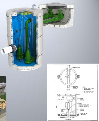


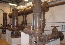
2 Application Problems Application Problems Go with the Flow PUMP SOURCE TREATMENT TRANSFER Lift Stations Same Function Packaged Differently Lift Stations Check Selection WET PIT PUMPING DRY PIT PUMPING 2

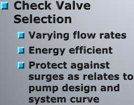
3 Application Problems Lift Stations VFD Pumping Creates Varying Flow Rates Pumping Velocity Matters Minimum Pumping Velocity: 4 FPS MAY NOT be 100% open Maximum Pumping Velocity: 15 FPS SHOULD be 100% open Do not exceed this rating Lift Stations - Varying Flow Rates Proper Sizing for Range of Flows Application Problems Fully Open s Do Not Restrict Flow Lift Stations - Varying Flow Rates Partially Open s Effect Headloss Energy Cost is 15% Open Restricted Flow What is Head-loss? ANSWER: The drop in the sum of pressure head, between two points along the path of a flowing fluid, due to causes such as fluid friction (through a valve, or a pipe). Partially Open s Restrict Flow 3
4 Horsepower Expressed as: Flow Coefficient (Cv) Size specific rating OR Resistance Coefficient (K factor) Dimensionless rating ALWAYS CALCULATED AT 100% OPEN Type of (12 ) Port Size Cv K Control 100% Silent Check 100% Swing Check 80% Dual Disc Check 80% Nozzle Check 100% Ball Check 100% Eccentric Plug 80% Surgebuster Check 100% Tilted Disc Check 140% Butterfly 90% Cone 100% 21, Ball 100% 22, Cost versus Energy Consumption Cost versus Energy Consumption High Cost Low Ball K=.03 Tilting Disc Check K=.63 Surge Buster Check K=.80 Energy Consumption Swing Check K=1.58 Booster Pump Control K=5.70 Silent Check K=2.95 High High Cost Low Surge Buster Check K=.80 Energy Consumption Swing Check K=1.58 High Annual Energy Cost Calculations Life Cycle Costs Purchase Costs Installation Costs Maintenance Costs Energy Costs Electrical Cost Per Year ( EC/Y ) = 1.65 x Q x ΔH x Sg x C x U E Where: A = Annual energy costs, dollars per year Q = Flow rate in Gallons Per Minute ΔH = Head Loss of valve (in ft of water) Sg = Specific Gravity of Water C = Cost of electricity, $/kw h U = usage (in percentage) E = Efficiency of pump/motor set 4
 S g 1 Cost of electricity, ($kw-hr) AVG for NJ** C 0.1278 Usage, percent x 100 (1.0 equals 24 hrs per day) U 1.")
 = 1.")
 E = Efficiency of pump/motor set Baseline Energy Costing Uses Lever & Weight Swing Check s Energy Cost Comparison Using Surgebuster Check Type 1-Year")
5 Annual Energy Cost Calculations Legend of Values Project location: Finish Water Pumping Application Conditions Discharge pumping pressure (in feet of head) Ft 150 Pumping Flow Rate (in GPM) Q 6500 Specific gravity, dimensionless water (water = 1.0) S g 1 Cost of electricity, ($kw-hr) AVG for NJ** C Usage, percent x 100 (1.0 equals 24 hrs per day) U 1.00 Efficiency of pump and motor set (0.80 typical) E 0.80 **Average NJ Commercial Electricity Rate is Courtesy of Annual Energy Cost Calculations Electrical Cost Per Year ( EC/Y ) = 1.65 x Q x ΔH x Sg x C x U E Where: A = Annual energy costs, dollars per year Q = Flow rate in Gallons Per Minute ΔH = Head Loss of valve (in ft of water) Sg = Specific Gravity of Water C = Cost of electricity, $/kw h U = usage (in percentage) E = Efficiency of pump/motor set Baseline Energy Costing Uses Lever & Weight Swing Check s Energy Cost Comparison Using Surgebuster Check Type 1-Year Energy Cost 5-Year Energy Cost 10-Year Energy Cost Baseline $7,766 $38,838 $77,667 Based on 100% Open 14 Type 1-Yr Energy Cost 5-Yr Energy Cost 10-Yr Energy Cost Baseline $7,766 $38,838 $77,667 Surge Buster Style $3,838 $19,193 $38,387 Energy Savings 1-Year $3,928 5-Year $19, Year $39,280 Based on 100% Open 14 Application Problems Lift Stations VFD Pumping and The System Curve Check s close when the system pressure is higher than the pumping pressure 5

Residual Forward Flow 2)Moment of Zero Velocity 3)Reverse Flow")

6 Lift Stations: Flat vs Steep Pump Curves Orientation Matters Surge Potential + Serviceability Check Slam Severe Impact on Excessive Stress On Components: Seat Disc Shaft Body High Potential for or System Failure Check s and Water Hammer Cause and Effect System Dynamics After Shutdown 1)Residual Forward Flow 2)Moment of Zero Velocity 3)Reverse Flow Pump Cause Of Water Hammer: 1. Check Allows Reverse Flow 2. Reverse Flow Gathers Momentum 3. Check Closes 4. Reverse Momentum Trapped 5. Pressure Surge Results 6. Pipes Stretch Instantaneously 6
7 Tank B creates greater potential for reverse flow and check valve slam than Tank A System Dynamics Tank B Elev.=100ft Tank A Reverse Flow and Water Hammer Every 1 ft/sec of reverse velocity will cause a water hammer (surge) of 50 psi upon check valve closure. Pump Check Elev.=0ft Methods To Prevent Check Slam Close Rapidly Minimize Reverse Flow OR Close Slowly Allow Reverse Flow Slowly Restrict Flow to zero Check Closing Speed Depends on.. Length of Disc Stroke Orientation of Disc in Flow Friction/Inertia of Disc Mechanical Assistance Lever, weight, spring Dampening Devices Air Cushion, Oil Dashpot Rapid Closing Check Short Disc Stroke Low Disc Friction Low Disc Inertia Restrictive Closing Stroke Spring Assistance System Dynamics After Shutdown 1)Residual Forward Flow 2)Moment of Zero Velocity 3)Reverse Flow Pump 7


8 Don t Get Slammed Application Problems Percent Full CV Red Lines = Swing Check 30% Open, 60% Flow Surgebuster 30% Open and 13% of Flow Green Lines = Swing Check 10% Open, 36% of Flow Surgebuster 10% open and 3% of flow Percent Opening Why do s Fail Prematurely? Knife vs Plug vs Gate vs Butterfly Mis- Application Piping Problems Improper Installation Knife gates and plug valves best suited for seating against solids and rags among four listed above for lift station isolation service. Knife Gates Are Designed for Solids Compact Design Plug s Rectangular and Round Ports A design difference that is subject to differing opinions. Surface area at plug. 8


9 2-Way Plug 3-Way Plug Most typical valve configuration, in waste water systems. Usually applied in locations where two valves and associated piping is space limited. 4-Way Plug Center Line of Body Plug Seat End Specialty valve rarely applied, but available. Eccentric Offset Center Line of Seat Clockwise to Close Direct Pressure Reverse Pressure 9


10 Reverse Pressure Application Problems Direct Pressure Don t Introduce Entrained Air Application Problems Sources of Entrained Air 10


 Column Separation Entrained Air Problems Columns Rejoining Create Surge The two columns are drawn together by vacuum Rejoining Column Entrained Air Problems")
11 Three General Sources (of Air) 1. Pipelines are initially filled with Air. 2. There is air in water 2% by volume. 3. Air enters through mechanical equipment. Air in Water is 2% by Volume 1000 feet of pipe contains a slug of air 20 FEET LONG if accumulated in one point 1 mile of pipe contains a slug of air 100 FEET LONG if accumulated in one point. This is true regardless of size of pipe Air Bubbles Raising To High Point, Increasing In Size Entrained Air Problems Typical Flowing Pipeline Highpoint, Without Air Air Collects At High Point Restricted Flow When the large air mass is forced downstream to the next high point, the restriction will cause a velocity change. This change in velocity may cause a pipeline surge. Entrained Air Problems Column Separation at High Points System Shuts Down (Power Failure, Pump Failure, etc.) As Water Drains, A Vacuum Forms at High Point. Draining Vacuum ( Negative Pressure ) Column Separation Entrained Air Problems Columns Rejoining Create Surge The two columns are drawn together by vacuum Rejoining Column Entrained Air Problems Result As columns rejoin, surge may take place causing system damage. Vacuum Damage to Pipeline 11
 Air Vacuum")

12 Entrained Air Problems Air Types Vacuum Damage to Water Storage Tank Types of Air s to Remove Entrained Air ARV = Air Release Releases air with pipeline under pressure AVV = Air/Vacuum Releases air only until pipeline is pressurized, breaks vacuum CAV = Combination Air Combines both functions of ARV/AVV Air Types Waste Water Air s Design Differences Clean Water Air Release s (WW-ARV) Air Vacuum (WW-AAV) Combination Air (WW-CAV) Air Types Wastewater Applications WW valve body is expanded to avoid internal fouling. Globe bottom increases float clearance reducing potential for clogging and float lock-up. Air Types Why Automatic Air s? Initial Line Filling Large Amounts of Air Exhaust Pump Start Up Skirted float more receptive to in-rush of media which helps to prevent clogging. Model 48A, for wastewater applications Flow Potential Water Levels 12


13 Air Types Why Automatic Air s? Air Types Why Automatic Air s? Pump Stop Large Amounts of Air Intake Vacuum Protection Pumping Small Amounts of Entrained Air at High Points Flow Flow Flow Waste Water ARV ARV Operation of Air Release s Closed Position Open Position Waste Water AVV Air s Operation of Air / Vacuum s 1 Open: Air exhausted during pipeline fill 3 Open: Air enters during pipeline draining 2 Closed: Pipeline under pressure 13


14 Why An Air / Vacuum Stays Closed Under Pressure Operation: Exhausts air during filling operations & 2 Outlet admits air during draining operations. Note: Does not vent air accumulated during system operation AVV Operation Seat Float Stem Guide Waste Water CAV Alternate Design for Dual Body WW CAV Note Back-washing Accessories Air Types Combination Air s - CAV Single Body Style Dual Body Style Air s Operation Of Combination Air s Open: Air exhausted during pipeline fill Pipeline Under Pressure: Accumulated air continually released Closed: Pipeline under pressure Open: Air enters during pipeline draining Air Sizing and Location 14


15 Air Sizing Parameters Evacuation of Air during pipeline filling not to exceed 1-2 feet per second (FPS) See AWWA Publication M-51 Primary Sizing Premise Free-flow condition in piping: Pipeline rupture As Water Drains, Velocity increases with slope. Air Sizing Parameters Exhaust Air expressed as SCFM (standard cubic feet/minute) Operating differential = 2 PSID for exhausting Use 5 PSID when using surge-check during exhausting Maximum operating differential = 5 PSID for vacuum breaking 7 PSID = Sonic Condition Air Sizing - ARV General Reference Chart Air Sizing - AVV Based on evacuating air on initial fill at a range of 1-2 feet per second (FPS) AVV Rule of Thumb = 1 of valve size per 1-0 Ft of pipe line size Val-Vatic Air Sizing Program Available CAV Sizing ARV and AVV Parameters apply Single Body Sizing more difficult on larger pipe lines Dual Body Combination Units can be custom-built Val-Vatic Air Sizing Program Available 15


16 Example: Air Sizing Report Example: Air Sizing Report Example of Proper Placement Air Location High Points: CAV Long Horizontal Runs: ARV or CAV at 1250 to 2500 ft intervals Long Descents: CAV at 1250 to 2500 ft intervals Air Location Air Location Long Ascents: AAV at 1250 to 2500 ft intervals Decrease in an up slope: AAV Increase in a down slope: CAV Place on or in close proximity to Mechanical Equipment 16


17 Air s at System High Points Air Sizing Air Sizing Program Available At Air Sizing Program Available Online For Additional Information: Fred Haines or Jason Chase or Carl Moser Telephone: www. Harper-Haines.com fhaines@harper-haines.com jchase@harper-haines.com cmoser@harper-haines.com Thank You for Your Time! 17
Theory, Application, and Sizing of Air Valves
 Theory, Application, and Sizing of Air Valves VAL-MATIC VALVE AND MANUFACTURING CORP. 905 RIVERSIDE DRIVE, ELMHURST, IL 60126 TEL. (630) 941-7600 FAX. (630) 941-8042 www.valmatic.com 1 THEORY, APPLICATION,
APCO SLOW CLOSING AIR/VACUUM VALVES
 BULLETIN 1 JULY 01 APCO SLOW CLOSING AIR/VACUUM VALVES Series 1900 APCO Slow Closing Air/Vacuum s Maximum Air Flow Velocity in Good Pipeline Design The Air/Vacuum operates in the normal fashion allowing
check valve slam A methodology for predicting
 BY JOHN V. BALLUN A methodology for predicting check valve slam USING A METHODOLOGY DEVELOPED BY EXTENSIVE TESTING, DESIGNERS CAN MATCH THE DYNAMICS OF A PUMPING SYSTEM WITH THE NONSLAMMING CHARACTERISTICS
Design and Selection Criteria of Check Valves
 Design and Selection Criteria of Check Valves VAL-MATIC VALVE AND MANUFACTURING CORP. 905 RIVERSIDE DRIVE, ELMHURST, IL 60126 TEL. (630) 941-7600 FAX. (630) 941-8042 www.valmatic.com Copyright 2011 Val-Matic
Module 9: Basics of Pumps and Hydraulics Instructor Guide
 Module 9: Basics of Pumps and Hydraulics Instructor Guide Activities for Unit 1 Basic Hydraulics Activity 1.1: Convert 45 psi to feet of head. 45 psis x 1 ft. = 103.8 ft 0.433 psi Activity 1.2: Determine
C. starting positive displacement pumps with the discharge valve closed.
 KNOWLEDGE: K1.04 [3.4/3.6] P78 The possibility of water hammer in a liquid system is minimized by... A. maintaining temperature above the saturation temperature. B. starting centrifugal pumps with the
VAL-MATIC VALVE AND MANUFACTURING CORP. 905 RIVERSIDE DRIVE, ELMHURST, IL 60126 TEL. (630) 941-7600 FAX.
 941-7600 FAX.") Cavitation in Valves VAL-MATIC VALVE AND MANUFACTURING CORP. 905 RIVERSIDE DRIVE, ELMHURST, IL 60126 TEL. (630) 941-7600 FAX. (630) 941-8042 www.valmatic.com CAVITATION IN VALVES INTRODUCTION Cavitation
Cavitation in Valves VAL-MATIC VALVE AND MANUFACTURING CORP. 905 RIVERSIDE DRIVE, ELMHURST, IL 60126 TEL. (630) 941-7600 FAX. (630) 941-8042 www.valmatic.com CAVITATION IN VALVES INTRODUCTION Cavitation
Air/Vacuum Valves. Removal of Air from Pipelines. Allow the Entry of Air into Pipelines. Application:
 /Vacuum Valves Micro-Irrigation and vacuum control is essential to the safety, longevity, efficiency, and performance of an irrigation system. must be allowed to exit pipelines 1) upon startup to prevent
LECTURE 28 to 29 ACCUMULATORS FREQUENTLY ASKED QUESTIONS
 LECTURE 28 to 29 ACCUMULATORS FREQUENTLY ASKED QUESTIONS 1. Define an accumulator and explain its function A hydraulic accumulator is a device that stores the potential energy of an incompressible fluid
HS-901(A) BASIC STEAM HEATING SYSTEMS
 BASIC STEAM HEATING SYSTEMS") HS-901(A) BASIC HEATING SYSTEMS One-Pipe Two-Pipe Basic Steam Heating Systems One-pipe steam heating system EQUALIZER SAFETY FACTOR STATIC HEAD PRESSURE DROP 2" HEATING UNIT 15" DRIP CONNECTION In a one-pipe,
HS-901(A) BASIC HEATING SYSTEMS One-Pipe Two-Pipe Basic Steam Heating Systems One-pipe steam heating system EQUALIZER SAFETY FACTOR STATIC HEAD PRESSURE DROP 2" HEATING UNIT 15" DRIP CONNECTION In a one-pipe,
WHAT YOU DON T KNOW ABOUT ACCUMULATORS CAN KILL YOU!
 WHAT YOU DON T KNOW ABOUT ACCUMULATORS CAN KILL YOU! Atlanta (Monroe) GA 770-267-3787 gpm@gpmhydraulic.com www.gpmhydraulic.com What You Don t Know About Hydraulic Accumulators Can Kill You TABLE OF CONTENTS
G. VULCANIZED SEAT Pressure sensitive seating with full disc overlap provides positive seating at high and low pressures.
 A B C D G F E J H I A. RETAINER PLUGS Retain hinge and stop pins while providing compression to stabilization spheres. B. STABILIZATION SPHERES Stabilize hinge and stop pins, preventing vibration and wear.
VAG Non-Return Valves
 VAG Non-Return Valves VAG SKR Slanted Seat Tilting Disk Check Valve Body Shaft Disk Bearing bush Seat Technical details Nominal pressure PN 10 / PN 16 Nominal diameter DN 200...1200 Fields of application:
MOBILE FIRE - RESCUE DEPARTMENT FIRE CODE ADMINISTRATION
 MOBILE FIRE - RESCUE DEPARTMENT FIRE CODE ADMINISTRATION Fire Pump Plan Review 2009 International Fire Code and NFPA 20 Date of Review / / BLD201 - Project Address: Project Name: Contractor s Business
Design of Sewage Pumping Stations by John Zoeller, PE, CEO/President
 Design of Sewage Pumping Stations by John Zoeller, PE, CEO/President This article provides guidelines for designing municipal pumping systems. There are three types of sewage handling systems: 1. Municipal
REGULATING VALVE APPLICATIONS
 REGULATING APPLICATIONS GENERAL REGULAR APPLICATION & INSTALLATION NOTES Regulator Application & Installation Notes The following are considerations for all steam regulator installations, as system operation
Fire Pump Plan Review March 2010
 Fire Pump Plan Review March 2010 Date of Review: / / Permit Number: Business/Building Name: Address of Project: Designer Name: Designer s Phone: Contractor: Contractor s Phone: Occupancy Classification:
Mustang Series PRESSURE REDUCING CONTROL VALVE WITH PRESSURE SUSTAINING FEATURE. M115-2 (Globe) M1115-2 (Angle) Schematic. Standard Components
 M1115-2 (Angle) Schematic. Standard Components") Schematic Throttles to reduce high upstream pressure to constant lower downstream pressure Throttles to maintain minimum upstream pressure PRESSURE REDUCING CONTROL VALVE WITH PRESSURE SUSTAINING FEATURE
Schematic Throttles to reduce high upstream pressure to constant lower downstream pressure Throttles to maintain minimum upstream pressure PRESSURE REDUCING CONTROL VALVE WITH PRESSURE SUSTAINING FEATURE
How Curve Shape Can Influence Pump Selection
 Pump ED 101 How Curve Shape Can Influence Pump Selection Joe Evans, Ph.D http://www.pumped101.com If you are new to the pump arena, you may be a bit taken back by the number of pump models offered by various
WATER MEASUREMENT USING TWO INCH (50 mm) DRAIN TESTS
 DRAIN TESTS") GAP.14.1.2.2 A Publication of Global Asset Protection Services LLC WATER MEASUREMENT USING TWO INCH (50 mm) DRAIN TESTS INTRODUCTION A hydrant or other large-volume flow test is necessary for proper water
GAP.14.1.2.2 A Publication of Global Asset Protection Services LLC WATER MEASUREMENT USING TWO INCH (50 mm) DRAIN TESTS INTRODUCTION A hydrant or other large-volume flow test is necessary for proper water
Surgebuster Check Valves
 Bulletin 7200 Innovative Design Optimum Performance Advanced Technology SURGEBUSTER! Surgebuster Check Valves www.valmatic.com AWWA C508 Certified NSF/ANSI 61 Certified for Drinking Water NSF/ANSI 372
Pressure drop in pipes...
 Pressure drop in pipes... PRESSURE DROP CALCULATIONS Pressure drop or head loss, occurs in all piping systems because of elevation changes, turbulence caused by abrupt changes in direction, and friction
Water hammering in fire fighting installation
 Water hammering in fire fighting installation Forward One of major problems raised in the fire fighting network installed at Pioneer company for pharmaceutical industry /Sulaymania was the high water hammering
Float and Thermostatic Traps Series H, C and X
 Hoffman Specialty Installation & Maintenance Instructions HS-(E) and Thermostatic Traps Series H, C and X Series C & NPT Series C NPT Series X NPT Series C NPT Series H Ratings Maximum Max. Operating NPT
Heating Water by Direct Steam Injection
 Heating Water by Direct Steam Injection Producing hot water by direct steam injection provides a solution where large volumes of hot water at precise temperatures are required, and where energy and space
Bulletin 9000 Ener G Ball Valve Cam- Centric Plug Valves American-BFV Butterfly Valves Tilted Disc Check Valves Silent Check Valves
 Bulletin 9000 High Performance Features G Surge Control F B E C H Bottom Mounted Oil Dashpot Top Mounted Oil Dashpot A D F A. Energy Efficient Body Ultra low headloss is the result of streamlined body
Material taken from Fluid Power Circuits and Controls, John S. Cundiff, 2001
 Pressure Control Chapter 3 Material taken from Fluid Power Circuits and Controls, John S. Cundiff, 2001 Introduction Pressure control is a key element in the design of any circuit. Used correctly, it can
FILLING AND PURGING THE SYSTEM
 FILLING INSTRUCTIONS FOR WATER HEATER OR CONDENSING BOILER (City Water) Safety tip: Before beginning, turn off power to boiler and circulator. FILLING AND PURGING Step 1: Close Return Manifold Isolation
TOPIC: 191004 KNOWLEDGE: K1.01 [3.3/3.5] Which one of the following contains indications of cavitation in an operating centrifugal pump?
![TOPIC: 191004 KNOWLEDGE: K1.01 [3.3/3.5] Which one of the following contains indications of cavitation in an operating centrifugal pump?](/thumbs/17/105210.jpg "TOPIC: 191004 KNOWLEDGE: K1.01 [3.3/3.5] Which one of the following contains indications of cavitation in an operating centrifugal pump?") KNOWLEDGE: K1.01 [3.3/3.5] P21 Which one of the following contains indications of cavitation in an operating centrifugal pump? A. Low flow rate with low discharge pressure. B. Low flow rate with high discharge
KNOWLEDGE: K1.01 [3.3/3.5] P21 Which one of the following contains indications of cavitation in an operating centrifugal pump? A. Low flow rate with low discharge pressure. B. Low flow rate with high discharge
Example. Fluid Power. Circuits
 Example Fluid Power Circuits To Enhance Symbol Reading Skills To Work On Circuit Reading Skills With Answers HI LO Pump Circuit 18 A1 B1 17 16 15 13 Set 14 2,000 PSI PG2 Set 500 PSI 12 11 7 8 10 PG1 9
Equivalents & Conversion Factors 406 Capacity Formulas for Steam Loads 407 Formulas for Control Valve Sizing 408-409
 Engineering Data Table of Contents Page No. I II Formulas, Conversions & Guidelines Equivalents & Conversion Factors 406 Capacity Formulas for Steam Loads 407 Formulas for Control Sizing 408-409 Steam
In-Line Air Separators
 Air Elimination & Control In-Line Air Separators The AC models of air separators deliver all the quality and performance you expect from Taco products. They are built to last with shell, heads and ANSI
Wastewater Collection Practice Test #3 Page 1 of 15
 Wastewater Collection Practice Test #3 Page 1 of 15 1) A 54 in. storm sewer flowing half full, at a velocity of 1.35 Ft./sec., will discharge how much flow into a creek in MGD? 13.85 MGD 10.73 MGD 1.85
PRESSURE REDUCING CONTROL VALVE
 Schematics Throttles to reduce high upstream pressure to constant lower downstream pressure Low Flow By-Pass controls at low flows 4 PRESSURE REDUCING CONTROL VALVE with LOW FLOW BY-PASS FEATURE Main Line
Surge Modeling Tips and Procedures Dr. Don J. Wood & Dr. Srinivasa Lingireddy
 Surge Modeling Tips and Procedures Dr. Don J. Wood & Dr. Srinivasa Lingireddy This Document contains a collection of answers to often asked questions, tips and advice for surge modeling. As always please
BLADDER SURGE CONTROL SYSTEM
 PART I GENERAL 1.01 Description BLADDER SURGE CONTROL SYSTEM This specification describes the requirements for a Bladder Surge Control System. The purpose of the system is to minimize transient pressures
Air Eliminators and Combination Air Eliminators Strainers
 Description Air Eliminators and Combination Air Eliminator Strainers are designed to provide separation, elimination and prevention of air in piping systems for a variety of installations and conditions.
Daniel. Liquid Control Valves Technical Guide. Technical Guide DAN-LIQ-TG-44-rev0813. DAN-LIQ-TG-44-rev0208. February 2008.
 DAN-LIQ-TG-44-rev0208 February 2008 Daniel Liquid Control Valves Technical Guide www.daniel.com Daniel Measurement and Control Theory, Principle of Operation and Applications This brochure has been prepared
ELECTRIC/DIESEL FIRE PUMP CHECK LIST
 BUILDING NAME: DESIGNER: SCO REPRESENTATIVE: PUMP MANUF.: LOCATION: INSTALLER: DATE: OWNER NAME: INSTALLATION Certificate for flushing and hydrostatic test furnished Piping been hydrostatically tested
Force Main Condition Assessment: New Technologies & Case Studies
 Force Main Condition Assessment: New Technologies & Case Studies Andy Dettmer, Ph.D., P.E. CMOM Workshop August 19, 2014 2 1 Three takeaways 1. Most of your force mains are good 2. We can pinpoint the
Flygt Ball Check Valves
 4/13 Supersedes: 6/96 The basic purpose of a check valve is to permit flow in one direction, prevent flow in the opposite direction and perform this function automatically and with minimum maintenance.
Centrifugal Fans and Pumps are sized to meet the maximum
 Fans and Pumps are sized to meet the maximum flow rate required by the system. System conditions frequently require reducing the flow rate. Throttling and bypass devices dampers and valves are installed
Selection Of Centrifugal Pumping Equipment 1
 Circular 1048 Selection Of Centrifugal Pumping Equipment 1 Dorota Z. Haman, Fedro S. Zazueta, Forrest T. Izuno 2 INTRODUCTION The pump is an essential component of an irrigation system. Proper selection
HYDRAULIC ANALYSIS OF PIPE LINED WITH MADISON S 100% SOLIDS STRUCTURAL POLYURETHANE COATINGS
 HYDRAULIC ANALYSIS OF PIPE LINED WITH MADISON S 100% SOLIDS STRUCTURAL POLYURETHANE COATINGS Shiwei William Guan, Ph.D. Vice President, R&D and International Business Madison Chemical Industries Inc. 490
61W - Wafer style resilient seated butterfly valve 61L - Lugged style resilient seated butterfly valve
 61W - Wafer style resilient seated butterfly valve 61L - Lugged style resilient seated butterfly valve Features Rounded polished disc edge gives full concentric sealing, lower torques, longer seat life
pressure inside the valve just before the final release of air. in pipeline systems resulting from 2p 1 p a m C D A o
 BY SRINIVASA LINGIREDDY, DON J. WOOD, AND NAFTALI ZLOZOWER It is a common practice to locate air valves at high elevations along water transmission mains. Improper sizing of an air valve could lead to
DARTMOUTH COLLEGE DESIGN January 3, 2012 & CONSTRUCTION GUIDELINES
 SECTION 15062 STEAM AND CONDENSATE PIPING PART 1 DESIGN DIRECTIVES 1.1 QUALITY ASSURANCE A. Comply with the provisions of the following: 1.2 DESIGN CRITERIA 1. ASME B 31.9 Building Services Piping : for
Standard Hydraulic Piping Flushing Procedure
 Page 1 of 6 1.0 Scope This procedure covers the minimum technical requirements for cleaning and flushing of Hydraulic and Piping, and related accessories. 2.0 Introduction In hydraulic fluid power systems,
MFP14, MFP14S and MFP14SS Automatic Pumps
 Page 1 of 6 TI-P136-02 ST Issue 12 Cert. No. LRQ 0963008 ISO 9001, S and SS utomatic Pumps Description The Spirax Sarco automatic pump is a displacement receiver operated by steam or compressed air. It
Oildyne. 165 Series Hydraulic Power Units. Pressures to 241 bar (3500 psi) Flows to 5.4 lpm (1.4 gpm)
 Flows to 5.4 lpm (1.4 gpm)") Oildyne Hydraulic Power Units Pressures to 241 bar (3500 psi) Flows to 5.4 lpm (1.4 gpm) 11 Power Unit Features We are pleased to introduce our new power units. The power units let you put more power where
Oildyne Hydraulic Power Units Pressures to 241 bar (3500 psi) Flows to 5.4 lpm (1.4 gpm) 11 Power Unit Features We are pleased to introduce our new power units. The power units let you put more power where
Most agencies think about cleaning because of debris in the line.
 Most agencies think about cleaning because of debris in the line. If we have an effective cleaning program there should not be a lot of debris in the line after the line is cleaned and tv d for acceptance.
AIR RELEASE, CLEANOUT, AND SEWER MANHOLES
 AIR RELEASE, CLEANOUT, AND SEWER MANHOLES **From Hartford IM BLDG(10) DESCRIPTION. This work shall consist of the construction of air release, cleanout, and sanitary sewer manholes; and the furnishing
MODEL WEB CONTENT FOR CITY SANITARY SEWER DEPARTMENTS
 MODEL WEB CONTENT FOR CITY SANITARY SEWER DEPARTMENTS The following information is designed to be used in conjunction with the Sewer Toolkit, located in the Wastewater section of the Florida Rural Water
The Secret of Hydraulic Schematics. BTPHydraulics www.iranfluidpower.com
 The Secret of Hydraulic Schematics BTPHydraulics www.iranfluidpower.com www.iranfluidpower.com Table of Contents The Secret to Reading and Interpreting Hydraulic Schematics... 1 Hydraulic System Schematics...
PUMPS TYPE OF PUMP PRESSURE/FLOW RATING CHARACTERISTICS. Centrifugal Low Pressure/High Flow Flow changes when
 PUMPS Pumps provide the means for moving water through the system at usable working pressures. The operation and maintenance of these pumps are some of the most important duties for many water utility
DIVISION OF WATER QUALITY CONSTRUCTION GRANTS & LOANS SECTION FAST TRACK AUDIT CHECKLIST
 DIVISION OF WATER QUALITY CONSTRUCTION GRANTS & LOANS SECTION FAST TRACK AUDIT CHECKLIST CERTIFICATION 1. Did the engineer submit a certificate of completion utilizing the appropriate page of the issued
2.0 DESIGN CRITERIA FOR WATER DISTRIBUTION SYSTEMS
 2.0 DESIGN CRITERIA FOR WATER DISTRIBUTION SYSTEMS Water system improvements proposed for inclusion into Western s service area shall be designed in accordance with all appropriate AWWA standards, include
Element D Services Plumbing
 PART 1 - GENERAL 1.01 OVERVIEW A. This section addresses domestic cold, hot and hot water return distribution systems within and to five feet beyond building perimeter. PART 2 - DESIGN CRITERIA 2.01 GENERAL
Guidelines for Precast Concrete Grease Interceptors
 Guidelines for Precast Concrete Grease Interceptors Purpose Provide an overview of the basic design principals that govern why gravity grease interceptors work Provide a forum for discussion of common
SunMaxx Solar Filling Station Operating Instructions
 SunMaxx Solar Filling Operating Instructions Content 1. Declaration of conformity... 2 2. Introduction... 2 3. Transportation and unpacking... 4 4. Mounting and commissioning... 5 5. End of operation...
Firefighter Review. Instructor Guide
 Firefighter Review Instructor Guide Session Reference: 3 Topic: Attack Line Handling Level of Instruction: Time Required: Three Hours Materials: Two Fully Equipped Pumpers Structure for Use in Advancing
Compressed Air Systems
 Efficiency Vermont Guide to Savings Helping Vermont businesses save energy and money Compressed Air Systems 888-921-5990 www.efficiencyvermont.com 1 Save money and optimize system performance Air compressors
Unit 24: Applications of Pneumatics and Hydraulics
 Unit 24: Applications of Pneumatics and Hydraulics Unit code: J/601/1496 QCF level: 4 Credit value: 15 OUTCOME 2 TUTORIAL 3 HYDRAULIC AND PNEUMATIC MOTORS The material needed for outcome 2 is very extensive
Practice Problems on Pumps. Answer(s): Q 2 = 1850 gpm H 2 = 41.7 ft W = 24.1 hp. C. Wassgren, Purdue University Page 1 of 16 Last Updated: 2010 Oct 29
: Q 2 = 1850 gpm H 2 = 41.7 ft W = 24.1 hp. C. Wassgren, Purdue University Page 1 of 16 Last Updated: 2010 Oct 29") _02 A centrifugal with a 12 in. diameter impeller requires a power input of 60 hp when the flowrate is 3200 gpm against a 60 ft head. The impeller is changed to one with a 10 in. diameter. Determine the
_02 A centrifugal with a 12 in. diameter impeller requires a power input of 60 hp when the flowrate is 3200 gpm against a 60 ft head. The impeller is changed to one with a 10 in. diameter. Determine the
Applying Pressure Independent Control Valves in H.V.A.C. Systems. A Presentation to: Orange Empire ASHRAE Santa Ana Nov. 17, 2009
 Applying Pressure Independent Control Valves in H.V.A.C. Systems A Presentation to: Orange Empire ASHRAE Santa Ana Nov. 17, 2009 1 Introduction I know, as building design consultants, so much of your effort
There are two sheets, Diesel and Electric, identified by tabs at the bottom of the sheet.
 Willard Says Absolutely fascinating information about practical hydraulic dredging. How To Use the Dredge Production Cost Spreadsheet This program guide describes the various dredge operating cost parameters
Minor losses include head losses through/past hydrants, couplers, valves,
 Lecture 10 Minor Losses & Pressure Requirements I. Minor Losses Minor (or fitting, or local ) hydraulic losses along pipes can often be estimated as a function of the velocity head of the water within
123 Industrial Loop Road Paynesville, MN 56362 Phone: 1-800-864-1649 www.master-mfg.com
 123 Industrial Loop Road Paynesville, MN 56362 Phone: 1-800-864-1649 www.master-mfg.com INTRODUCTION The purpose of this manual is to assist you in the assembly, operation and maintenance of your sprayer
Irrigation Pump Variable Frequency Drive (VFD) Energy Savings Calculation Methodology. Public Utility District No. 1 of Chelan County
 Energy Savings Calculation Methodology. Public Utility District No. 1 of Chelan County") Irrigation Pump Variable Frequency Drive (VFD) Energy Savings Calculation Methodology Public Utility District No. 1 of Chelan County This paper describes how to calculate energy saved by installing a variable
Irrigation Pump Variable Frequency Drive (VFD) Energy Savings Calculation Methodology Public Utility District No. 1 of Chelan County This paper describes how to calculate energy saved by installing a variable
08.08 Vic-Check Valves
 The check valves are a product of computer-assisted innovative engineering with quality features including a new hydrodynamically efficient profile. The Vic-Check valve utilizes a spring-assisted, single-disc
Goulds Water Technology
 APPLICATIONS Specifically designed for: Homes Farms Cottages Booster service SPECIFICATIONS Pump: Pipe connections: 1¼" NPT suction, 1" NPT discharge, 1" NPT drive (pressure) Pressure switch: AS4 preset
Morrison Bros. Co. General Product Specifications
 Morrison Bros. Co. General Product Specifications Tank Mounted Spillbox The spill containment device is manufactured to contain spills and drips that may occur at the fill point on aboveground storage
BPW32 DN15, DN20 and DN25 Balanced Pressure Wafer Steam Trap
 1263050/6 IM-P126-07 ST Issue 6 BPW32 DN15, DN20 and DN25 Balanced Pressure Wafer Steam Trap Installation and Maintenance Instructions 1. Safety information 2. General product information 3. Installation
ACCUMULATOR INSTALLATION
 7001-7 ACCUMULATOR INSTALLATION BRAKE ACCUMULATORS I 308L93 Rae 7-59710 Issued 6-93 Printed in U.S.A 7001-8 Removal ACCUMULATOR VALVE 1. Park the machine on a level surface and lower the. loader bucket
Pressure Locking & Thermal Binding In Wedge Gate & Parallel Slide Gate Valves
 Pressure Locking & Thermal Binding In Wedge Gate & Parallel Slide Gate Valves CRANE Energy Flow Solutions TM Donald H. Johnson Crane Energy Flow Solutions 1 Crane Co. Resolution Made By Richard Teller
Owner s Manual. 5600 / 5600 Econominder
 5600 / 5600 Econominder Owner s Manual For questions or in case of emergency, please call your local service technician (preferably the one who installed the system). Product Features, Benefits, & Job
BERMAD Fire Protection
 Model: 400E-2M BERMAD Electrically Controlled Deluge Valve with Easy Lock Manual Reset Installation Operation Maintenance Safety First BERMAD believes that the safety of personnel working with and around
CENTRIFUGAL PUMP OVERVIEW Presented by Matt Prosoli Of Pumps Plus Inc.
 CENTRIFUGAL PUMP OVERVIEW Presented by Matt Prosoli Of Pumps Plus Inc. 1 Centrifugal Pump- Definition Centrifugal Pump can be defined as a mechanical device used to transfer liquid of various types. As
Flow Measurement Options for Pipeline and Open Channel Flow
 Flow Measurement Options for Pipeline and Open Channel Flow October 2013 Presented by Molly Skorpik - 2013 Montana Association of Dam and Canal Systems Conference Irrigation Training and Research Center
138.255 Section 4 Page 2. Flow in Pipes
 Flow in Pipes 138.255 Section 4 Page 2 Flow in Pipes 1.0 INTRODUCTION In this module we are focusing on the fundamental principles of headloss and we learn how to use headloss charts to estimate the headloss
PC1130 Electric Air Compressor
 Senco Products Inc. 8485 Broadwell Road Cincinnati, Ohio 45244 PC1130 Electric Air Compressor Operating Instructions 2006 by Senco Products, Inc. Warnings for the safe use of this tool are included in
Unit 24: Applications of Pneumatics and Hydraulics
 Unit 24: Applications of Pneumatics and Hydraulics Unit code: J/601/1496 QCF level: 4 Credit value: 15 OUTCOME 2 TUTORIAL 4 DIRECTIONAL CONTROL VALVES The material needed for outcome 2 is very extensive
That s it, that s what we do: air knife drying. Ray Ralph, President R.E. Morrison Equipment Inc.
 Post Shrink Tunnel Drying Air Knife Belt Cleaning Systems Conveyorized Drying Systems Bolt-On Air Knife Systems Air Knife Belt Defrosters Crate and Tote Drying Booster Blowers Vacuum Pumps for Carton Erecting
Installation Manual. Solar Pool Heating System. Read the complete manual before beginning the installation
 Solar Pool Heating System Installation Manual Read the complete manual before beginning the installation 1. Sizing the System Visit www.techno-solis.com to size the system using the sizing calculator.
Building Performance With District Cooling
 Reprinting this proof for distribution or posting on web sites is not permitted. Authors may request permission to reprint or post on their web site once the fi nal version has been published. A reprint
Pump ED 101. Positive Displacement Pumps. Part I Reciprocating Pumps
 Pump ED 101 Positive Displacement Pumps Part I Reciprocating Pumps Joe Evans, Ph.D http://www.pumped101.com There are many pump designs that fall into the positive displacement category but, for the most
08.09. Triple Service Valve Assembly
 SEE VICTAULIC PUBLICATION 10.01 FOR DETAILS Victaulic Tri-Service valve is an assembly (shipped as individual components) of a standard Victaulic butterfly or Vic-Plug valve and a check valve. This combination
Steam Coil Installation, Operation and Maintenance
 Steam Coil Installation, Operation and Maintenance Guidelines for the installation, operation and maintenance of the Heatcraft brand of steam heating coils manufactured by Luvata in Grenada, MS have been
Installation, Maintenance, & Repair Series 4000B/LF4000B
 Installation, Maintenance, & Repair Series 4000B/LF4000B Reduced Pressure Zone Assemblies Sizes: 1 2" 2" (15 50mm) RP/IS-A-4000B 4000B/LF4000B Size: 3 /4"! WARNING Testing Read this Manual BEFORE using
THE ADVANCED DENTAL DRY VAC DENTAL SYSTEMS
 TM THE ADVANCED DENTAL DRY VAC 100% Oil & Water Free Suction Systems Compact & Expandable Suction Systems Custom Engineered Large Scale Systems Portable Surgical Suction Systems The creation of vacuum
TD10. Selecting Circulators. Technical Documents. Taco Radiant Made Easy Application Guide STEP 1: ESTABLISH THE TARGET FLOW RATE FOR THE SYSTEM
 EFFECTIVE:August, Taco Radiant Made Easy Application Guide Selecting Circulators Technical Documents TD SUPERSEDES: New This article shows you how to select a Taco circulator that lets the hydronic system
BULLETIN NO. TEH-908. Bell & Gossett R T. Hydronic System Design with the Bell & Gossett System Syzer / ON GPM FLOW
 2000 BULLETIN NO. TEH-8 Bell & Gossett Hydronic System Design with the Bell & Gossett System Syzer 2 T 3 4 AT R T DIF URE TEMPERA 5 6 2M 7 8 9 10 3M 1 1M 800 600 0 400 GPM/T / ON GPM FLOW P PIPING FRICTION
Unit 24: Applications of Pneumatics and Hydraulics
 Unit 24: Applications of Pneumatics and Hydraulics Unit code: J/601/1496 QCF level: 4 Credit value: 15 OUTCOME 2 TUTORIAL 2 HYDRAULIC AND PNEUMATIC CYLINDERS The material needed for outcome 2 is very extensive
Rexroth Hydraulic Pump A10VO Series User Manual
 Rexroth Hydraulic Pump A10VO Series User Manual Rexroth Hydraulic pump A10VO Series User Manual Revised 5/1/2009 Page 1 of 12 Functional Purpose This pump is preferred over a fixed displacement (gear)
CONTROL VALVE PRESSURE DROP AND SIZING
 CONTENT Chapter Description Page I Purpose of Control Valve II Type and Main Components of Control Valve 3 III Power 5 IV. Pressure Drop Across Control Valve 7 V. Symbols and Units 10 VI. Unit Conversion
Septic Tank Use & Maintenance Tips
 Yellowhead County Hamlet of Cadomin Septic Tank Use & Maintenance Tips This guide gives an overview of the responsibilities for property owners in Cadomin. For Seasonal, Permanent & Vacationing Cadomin
2.0 BASIC CONCEPTS OF OPEN CHANNEL FLOW MEASUREMENT
 2.0 BASIC CONCEPTS OF OPEN CHANNEL FLOW MEASUREMENT Open channel flow is defined as flow in any channel where the liquid flows with a free surface. Open channel flow is not under pressure; gravity is the
MANURE COLLECTION AND TRANSFER SYSTEMS IN LIVESTOCK OPERATIONS WITH DIGESTERS. A. C. Lenkaitis GEA Farm Technologies Inc. (Houle USA), Naperville, IL
, Naperville, IL") MANURE COLLECTION AND TRANSFER SYSTEMS IN LIVESTOCK OPERATIONS WITH DIGESTERS A. C. Lenkaitis GEA Farm Technologies Inc. (Houle USA), Naperville, IL INTRODUCTION Manure collection systems are influenced
MANURE COLLECTION AND TRANSFER SYSTEMS IN LIVESTOCK OPERATIONS WITH DIGESTERS A. C. Lenkaitis GEA Farm Technologies Inc. (Houle USA), Naperville, IL INTRODUCTION Manure collection systems are influenced
DIESEL FUEL CONDITIONING
 COD FILTRATION DIESEL FUEL CONDITIONING REMOVE WATER & PARTICLES TO EXTEND FUEL INJECTOR LIFE & INCREASE COMBUSTION ENGINE FUEL EFFICIENCY Remove free water to saturation point with high single pass efficiency