CONTENTS. EasyPIC5 KEY FEATURES 4 CONNECTING THE SYSTEM 5 INTRODUCTION 6
|
|
|
- George Craig
- 9 years ago
- Views:
Transcription
1
2
3 CONTENTS EasyPIC5 KEY FEATURES 4 CONNECTING THE SYSTEM 5 INTRODUCTION 6 Switches 7 Jumpers 8 MCU Sockets 9 Power Supply 11 On-Board USB 2.0 Programmer 12 Oscillator 14 mikroicd (Hardware In-Circuit Debugger) 16 LEDs 17 Reset Circuit 19 Push Buttons 20 7-segment Displays 22 2x16 Character LCD 23 Graphic LCD 24 Touch Panel 25 RS-232 Communication Module 26 USB Communication Module 27 PS/2 Communication Module 28 DS1820 Digital Thermometer 29 A/D Converter Test Inputs 30 Direct Port Access Connectors 32

4 4 EasyPIC5 KEY FEATURES 1. External power supply connector 8-16V AC/DC; 2. Power supply selector. It is possible to use external or USB power supply. When using USB port, there is no need for external power supply; 3. Power ON/OFF switch; 4. On-board USB programmer with mikroicd support. Its key feature is an ability to upgrade. By downloading a new software, it will be possible to program new MCUs in coming years; 5. RS-232 communication module with selectable TX and RX for all microcontrollers; 6. USB port for MCU with USB support; 7. PC keyboard connector; 8. DS1820 temperature sensor connector; 9. A/D input selector used for testing the operation of A/D converter. It is connected to potentiometers P1 and P2; segment displays in multiplex mode; pin connector allows an easy connection of LCD; 12. LCD contrast potentiometer; 13. DIP switch SW6 turns on/off LEDs on ports A, B, C, D and E and enables digits on 7-segment LED display. DIP switch SW9 turns on/off touch panel controller, PS/2 and LCD and GLCD backlights; 14. EasyPIC5 supports microcontrollers in DIP8, DIP14, DIP18, DIP20, DIP28 and DIP40 packages; 15. Jumper to determine port performance in idle state (pullup/pull-down). Select pull-up to enable port pins to detect logic zero (0) and vice versa; 16. PORTA connected to a resistor network using DIP switch SW1. If a switch is OFF, the appropriate pin does not have a resistor attached. It enables PORTA pins to be used in analog mode as well as digital I/O pins. The same applies to other ports: PORTB, PORC, PORTD and PORTE; LEDs connected to the microcontroller I/O ports; pin connector allows an easy connection of graphic LCD; 19. Graphic LCD contrast potentiometer; 20. Reset circuit; push buttons allow control of every pin on the microcontroller; 21. Jumper to select high/low state of an input pin when the appropriate push button is pressed; 23. Touch panel connector; and 24. Touch panel controller.
5 CONNECTING THE SYSTEM 5 Apart from this manual, the development system box contains development system, product CD, USB cable and user manuals for PICflash programmer, mikroicd Debugger and Installing USB drivers. In order to use the EasyPIC5 properly, it is necessary to go through the following steps: Step no.1 Step no.2 Step no.3 Step no.4 Take the development system and product CD out of the box. Insert the product CD into CD drive. Do not connect the development system to a PC yet. Install PICflash programmer software to enable a program to be transferred from PC to the microcontroller chip. For detailed installation instructions refer to the PICflash programmer manual. Install USB drivers on your PC to enable programmer's hardware to operate properly on the EasyPIC5 board. For detailed installation instructions refer to the Installing USB drivers manual. Connect the EasyPIC5 to PC using USB cable. Please use one of the USB ports on the back of the PC because these are directly connected to the computer motherboard. If you turn ON the power supply switch on the EasyPIC5 board for the very first time, your PC will immediately detect a new hardware. You will be immediately prompted whether Windows should search for new drivers update or not. Select the option No, not this time and click Next. Another window appears, click Next and the operating system will automatically find the drivers. Click Finish to complete this process and run PICflash as explained in the PICflash programmer manual. After these four steps, your EasyPIC5 is successfully installed and ready for use. You can read a program from the chip or write another one into it. The product CD provides numerous simple program examples to make your first steps Easy... CONNECTING THE SYSTEM.

6 6 INTRODUCTION INTRODUCTION The EasyPIC5 is a full-featured development system for almost all Microchip PIC microcontrollers. It is designed to allow students and engineers to easily test and explore the capabilities of PIC microcontrollers. It also allows PIC microcontrollers to be interfaced with external circuits and a broad range of peripheral devices. The user can therefore concentrate on software development only. Figure 1 illustrates the EasyPIC5 development system. There are identification marks next to each component on a silkscreen, both on the top and bottom. These marks describe connection to the microcontroller, operation modes and provide additional useful information so that there is almost no need for additional schematics. Figure 1 EasyPIC5 development system

7 SWITCHES 7 The EasyPIC5 development system features a number of peripheral devices. In order to enable these before programming, the appropriate jumpers or switches have to be properly set. Switches are mechanical devices used to establish or break connection between two contacts. As for this system, switches are grouped in nine DIP switches. DIP switches SW1 - SW5 are used to enable external pull-up/pull-down resistors on port pins. Each pull-up/pull-down resistor is individually enabled. DIP switch SW6 is used to enable/disable LEDs connected to the microcontroller ports. Each group of 8 port LEDs has its own switch. Four lower switches in this group are used to enable/disable 7- segment LED displays. Each display digit can be individually enabled. SWITCHES DIP switches SW7 and SW8 select MCU pins to be used as RX or TX in serial communication. DIP switch SW9 is used to control both LCD backlights, communication via PS/2 connector and touch panel driver. Figure 2 illustrates the DIP switch SW9. As seen, switches 1, 2, 3 and 4 are ON, whereas 5, 6, 7 and 8 are OFF. Figure 2 DIP switch SW9

8 8 JUMPERS JUMPERS Similarly, jumpers are used to break or establish connection between two points. Under the plastic cover of a jumper, there is a metal contact which establishes connection when the jumper is placed over two pins. Figure 3 Jumper as a switch Jumper is commonly used as a selector between two possible connections via 3-pin connector. As illustrated in Figure 4, the middle connector pin can be connected to the left or right pin, depending on the jumper s position. Jumper is not placed and middle pin is unconnected. Jumper is placed on the left side connecting middle and left pin. Jumper is placed on the right side connecting middle and right pin. Figure 4 Jumper as a multiplexer

9 MCU SOCKETS 9 The EasyPIC5 comes with a 40-pin microcontroller PIC16F887. The user can remove this microcontroller and fit another one in DIP40, DIP28, DIP20, DIP18, DIP14 or DIP8 package into MCU socket. MCU SOCKETS Figure 5 MCU sockets Note: There are two DIP18 sockets with different pinouts (DIP18A and DIP18B). If you use 18-pin microcontrollers, make sure to select the right socket. For example, PIC18F1220 uses DIP18A socket, while PIC16F628A uses DIP18B socket. All 8-pin microcontrollers use DIP8 socket. The exception is PIC10F family which uses 10F MCU socket. Note: Note: Since all packages have parallel connections, it is not allowed to have more than one microcontroller on the board at a time. Some of the 28-pin PIC microcontrollers use the seventh pin as RA5, while some of them use this pin as VCC. Depending on this, jumper J18 must be set in RA5 and VCC position, respectively. For example, if you use the PIC18F2331 microcontroller, jumper J18 has to be set in VCC position.

10 10 The microcontroller pins are routed to various peripherals as illustrated in Figure 6. All MCU ports are directly connected to Direct Port Access 2x5 (10-pin) connectors. These are normally used for connecting external peripherals to the board or as points for digital logic probe connecting. MCU SOCKETS All ports are connected to LEDs and push buttons, which allows you to easily test and monitor digital pin state. Some of the pins are connected to on-board peripherals, such as DS1820 temperature sensor, RS- 232 communication module, 7-segment displays, LCD etc. Figure 6 System connection
. When using power supply over USB cable, jumper J6 should be set in the right-hand position. When using external power supply, the EasyPIC5 board produces +5V using LM7805 voltage regulator.")
11 POWER SUPPLY 11 Figure 7 Power supply connector The EasyPIC5 can use one out of two power supply sources - PC power supply over USB cable (by default) or external power supply (external AC/DC power adapter). When using power supply over USB cable, jumper J6 should be set in the right-hand position. When using external power supply, the EasyPIC5 board produces +5V using LM7805 voltage regulator. The external power supply can be AC or DC, while its voltage ranges between 8 and 16V. In this case jumper J6 should be set in the left-hand position. Figure 9 illustrates USB and external power supply circuit diagram. POWER SUPPLY Figure 9 Power supply circuit diagram J6 in the left-hand position: system is powered from external AC/DC power adapter. J6 in the right-hand position: system is powered from PC over USB cable. Figure 8 Power supply select jumper

12 12 ON-BOARD USB 2.0 PROGRAMMER ON-BOARD USB 2.0 PROGRAMMER There is no need to use external equipment during programming as the EasyPIC5 development system has its own on-board USB 2.0 programmer. All you need to do is to connect the system to PC using the USB cable. Then, load your program into the microcontroller via the PICflash programming software supplied with the EasyPIC5 board. Please refer to PICflash documentation for more information. Figure 10 USB 2.0 programmer There are two different programming modes for PIC MCUs: Low-Voltage and High-Voltage. Some of the PIC MCUs are shipped with Low-Voltage programming mode enabled by default. PICflash is a High-Voltage programmer only and it can program MCUs regardless of whether they have Low- Voltage programming mode enabled or disabled. In the USB programmer section there is the jumper group J10. These jumpers are used for PGM pin selection. The PGM pin is used to enter programming mode when Low-Voltage programming is enabled. As the Low-Voltage programming mode is not supported by PICflash programmer, this jumper group J10 should remain in default position. Figure 11 J10 jumpers Note: There is no need to reset MCU after programming because it will be automatically cleared by the programmer.
 as shown in Figure 12. When using DIP8, DIP14 and DIP20 sockets, these jumpers should be set in the lower position as shown in Figure 13.")
13 Figure 12 J8 and J9 for DIP28, DIP40, DIP18A and DIP18B 13 Figure 13 J8 and J9 for DIP8, DIP14 and DIP20 When using DIP28, DIP40, DIP18A and DIP18B sockets, jumpers J8 and J9 should be set in the upper position (default) as shown in Figure 12. When using DIP8, DIP14 and DIP20 sockets, these jumpers should be set in the lower position as shown in Figure 13. Jumper J7 allows the use of the MCLR pin as a RESET or a digital I/O pin. It can be RE3, RA5 or RA3 pin depending on MCU in use. When J7 is in lower position, the hardware reset is enabled by pressing the reset button. The MCLR pin cannot be used as I/O pin. When J7 is in upper position, the MCLR pin can be used as I/O pin. Hardware reset is disabled in this case. ON-BOARD USB 2.0 PROGRAMMER Figure 14 J7 jumper

14 14 OSCILLATOR OSCILLATOR The EasyPIC5 enables you to use microcontrollers fitting eight different sockets. Since these are not close to each other, there are two on-board clock oscillators. One of them, denoted by OSC1, is connected to DIP28, DIP40, DIP18A and DIP18B sockets. Another one, denoted by OSC2, is connected to DIP8, DIP14 and DIP20 sockets. There are identification marks next to each MCU socket on a silkscreen indicating which oscillator should be used. Quartz crystal is placed in the X1 socket by default. If you use OSC2, it is necessary to remove it from the X1 socket and place it in the X2 socket. Figure 15 Oscillators Note: 10F MCU socket is not connected to either oscillator. The appropriate MCUs have only an internal oscillator and do not use quartz crystal. Refer to the Figure above.

15 On some of the microcontrollers, oscillator input pins can also be used as digital input/output pins. In order to implement this feature, the EasyPIC5 has jumpers enabling MCU to be connected to either oscillator or digital I/O pins. Refer to the schematic of the OSC oscillator in Figure OSCILLATOR Figure 16 Oscillator connection with MCU
 and EEPROM while the program is running.")
16 16 MikroICD (IN-CIRCUIT DEBUGGER) MikroICD (IN-CIRCUIT DEBUGGER) MikroICD is a highly effective tool for Real-Time debugging on hardware level. The mikroicd debugger enables you to execute a program on PIC microcontroller and view variable values, special function registers (SFRs) and EEPROM while the program is running. MikroICD can be used with any PIC compiler manufactured by MikroElektronika (mikroc, mikrobasic or mikropascal). You just have to select the appropriate build type (Release or ICD Debug), build a project, program the MCU and run debugger. The mikroicd debugger uses on-board programmer to communicate with the compiler and supports common debugger commands: Start Debugger Run/ Pause Debugger Toggle Breakpoints Run to cursor Step Into Step Over Stop Debugger [F9] [F6] [F5] [F4] [F7] [F8] [Ctrl+F2] Figure 17 On-Board USB programmer with mikroicd Note: For more information on how to use mikroicd debugger please refer to the mikroicd User s Manual. You can also find it in Help documentation inside any of the before mentioned compilers.

17 LEDs 17 Light Emitting Diodes (LEDs) are components used for displaying pin digital state. The EasyPIC5 has 36 LEDs connected to the microcontroller PORTA, PORTB, PORTC, PORTD and PORTE. Each group of eight port LEDs can be enabled or disabled using switches of the DIP switch SW6. The exception is PORTE which has four LEDs and shares the same switch with PORTA. Port LEDs are enabled when the corresponding switch of the DIP switch SW6 is ON. In this case, LEDs will display the state of the corresponding microcontroller pin. Otherwise, the LEDs are always off, no matter what the port state is, as no current can flow through them. LEDs Figure 18 LEDs

18 18 Figure 19 illustrates the connection between LEDs and PORTB. Resistors are serially connected to the LEDs in order to limit their current. In this case the resistor value is 1K. LEDs Figure 19 LEDs circuit diagram

19 RESET CIRCUIT 19 Apart from 36 push buttons provided on the board, there is one red button on the far left marked as RESET. As its name suggests it is used for MCU reset. RESET CIRCUIT Figure 20 Reset button As seen in Figure 21, the microcontroller MCLR pin is connected to the programmer instead of being directly connected to the RESET button. Figure 21 Reset switch circuit diagram

20 20 PUSH BUTTONS PUSH BUTTONS Figure 23 Push buttons The EasyPIC5 has 36 push buttons which can be used to change states of digital inputs on the microcontroller ports. Connection between buttons and PORTA, PORTB, PORTC, PORTD and PORTE is shown in Figure 22. Jumper J17 determines whether a button press will bring logic zero (0) or logic one (1) to the appropriate pin. When the button is released, the pin state is determined by pull-up or pull-down port jumpers. As seen in the Figure below, J17 is connected to +5V, which means that the button press will bring logic one (1) to the appropriate pin. Figure 22 Push buttons circuit diagram
21 21 Referring to Figure 24, jumper J2 is set to pull-up, so that pull-up resistor pulls the microcontroller pin RB4 to +5V. By pressing the button, the RB4 pin is connected to ground via J17. Accordingly, only when the button is pressed the microcontroller senses a logic zero (0). Otherwise, the pin state will always be a logic one (1). PUSH BUTTONS Figure 24 Button with pull-up resistor Referring to Figure 25, switch J2 is set to pull-down, so that pull-down resistor pulls the microcontroller pin RB4 to 0V. By pressing the button, the RB4 pin is connected to +5V via J17. Accordingly, only when the button is pressed the microcontroller senses a logic one (1). Otherwise, the pin state will always be a logic zero (0). Figure 25 Button with pull-down resistor

22 22 7-SEGMENT DISPLAYS 7-SEGMENT DISPLAYS Figure 26 7-segment displays The EasyPIC5 has four 7-segment displays set up to operate in multiplex mode. Data lines are connected to PORTD, while each display is enabled by four PORTA bits. Common marking of 7-segment display segments Figure 27 7-segment display circuit diagram

23 2X16 CHARACTER LCD 23 A standard character LCD is probably the most widely used data visualization component. It usually displays messages in two lines, containing up to 16 alphanumeric characters each. The character LCD communicates with the microcontroller via 4-bit data bus. Figure 29 illustrates its connection to the microcontroller. Figure 28 2x16 LCD in 4-bit mode 2X16 CHARACTER LCD Figure 29 2x16 LCD circuit diagram Note: Have in mind that LCD should be placed or removed from the EasyPIC5 only after the power is turned off.

24 24 GRAPHIC LCD GRAPHIC LCD A graphic LCD (GLCD) provides an advanced method for displaying visual messages. While a character LCD can display only alphanumeric characters, a GLCD can be used to display messages in the form of drawings and bitmaps. The most commonly used graphic LCD has the screen resolution of 128x64 pixels.the GLCD contrast can be adjusted using the potentiometer P3 placed right above the GLCD. Figure 30 GLCD Figure 31 GLCD circuit diagram Note: Have in mind that GLCD should be placed or removed from the EasyPIC5 only after the power is turned off.

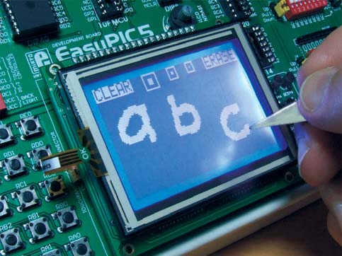
25 TOUCH PANEL 25 Touch panel is a tin, self-adhesive, transparent panel which could be placed over the screen of graphic LCD. It consists of two separate foils which form a sandwich structure. It is very sensitive to press so that even a soft touch causes some changes on the output signal. It is used in various user-friendly devices in combination with graphic LCD. Connector CN13 enables this device to be connected to on-board touch panel controller the active part of which consists of 5 discrete transistors. Four switches of the DIP switch SW9 enable or disable connection between this controller and RA0, RA1, RC0 and RC1 pins. TOUCH PANEL Figure 32 Touch panel Figure 33 Touch panel circuit diagram

26 26 RS-232 COMMUNICATION MODULE RS-232 COMMUNICATION MODULE Figure 34 RS-232 module RS-232 communication module enables point-to-point data transfer. It is commonly used in data acquisition applications to transfer data between the microcontroller and PC. Since the voltage levels of the microcontroller and PC are not directly compatible with each other, a level converter, such as MAX232, must be used. In order to provide more flexible system, the microcontroller is connected to the MAX232 via the DIP switches SW7 and SW8. The DIP switch SW7 is used to connect Rx line to RC7, RB2, RB1, RB4, RA3 or RB5. The DIP switch SW8 is used to connect Tx line to RC6, RB5, RB2, RB1, RA2 or RB7. Note that pin RB2 must not be simultaneously connected to Rx and Tx line. If you want to implement hardware handshaking, it is necessary to connect the RB0 pin to CTS line and the RC2 pin to RTS line using the DIP switch SW7. Figure 35 Connection between microcontroller and PC

27 USB COMMUNICATION MODULE 27 USB communication connector is placed in the upper right corner of the EasyPIC5. It is used with PIC microcontrollers having USB support,such as PIC18F2450 or PIC18F4550. Note that this USB connector cannot be used for programming. In order to make connection between the microcontroller and USB connector, the J12 jumper group should be set in the right-hand position. As a result, the microcontroller pins RC3, RC4 and RC5 are disconnected from the rest of the board and connected to the USB connector. Figure 36 USB connector USB COMMUNICATION MODULE Figure 37 USB communication circuit diagram

28 28 PS/2 COMMUNICATION MODULE PS/2 COMMUNICATION MODULE Figure 38 PS/2 connector PS/2 connector allows the EasyPIC5 to be directly connected to devices such as PC, keyboard or mouse. The PS/2 communication is of half-duplex type. It means that the microcontroller can be connected to a keyboard to capture pressed keys or to a PC to act as a keyboard. CLK line is used for clock transfer, whereas DATA line is used for data transfer. In this case, these lines are connected to the RC1 and RC0 pins, respectively. Figure 39 PS/2 communication circuit diagram
.")
29 DS1820 DIGITAL THERMOMETER 29 DS1820 digital thermometer is convenient for environmental temperature measurement. It can measure temperature in the range between -55 C and 125 C with 0.5 C accuracy. It must be properly placed in the 3-pin socket provided on the EasyPIC5, with its rounded side directed to the right, as marked on the board (refer to the Figure 41 below). Otherwise, the DS1820 could be permanently damaged. The DS1820 data pin can be connected to either RA5 or RE2 pin, which is determined by the jumper J11. Figure 40 DS1820 connector DS1820 DIGITAL THERMOMETER Figure 41 DS1820 circuit diagram
.")
30 30 A/D CONVERTER TEST INPUTS A/D CONVERTER TEST INPUTS There are many applications of A/D conversion. The microcontroller takes an analog signal from its input pin and converts it into a digital value. Basically, you can measure any analog signal that fits in the range acceptable by PIC (0 - VCC). Figure 42 A/D Converter input The EasyPIC5 development system has two potentiometers used to adjust the level of analog signals in order to test the operation of analog-to-digital converter (ADC). Both potentiometers outputs have voltage in the range of 0-5V. These two analog signals can be connected to different analog input pins simultaneously. The jumper group J15 enables the P1 potentiometer to be connected to one of the following pins: RA0, RA1, RA2, RA3 or RA4. The jumper group J16 enables the P2 potentiometer to be connected to one of the following pins: RA1, RA2, RA3, RA4 or RA5. In order to measure an analog signal without interference, turn off the corresponding switch of the DIP switch SW1. This will disable connection between PORTA pins and pull-up/down resistors.

31 31 Potentiometer P1 is connected to the RA2 pin and potentiometer P2 to the RA3 pin. Pull-up/down resistors on PORTA analog input pins should be disabled using the DIP switch SW1. A/D CONVERTER TEST INPUTS Figure 43 A/D Converter input circuit diagram Note: When the both potentiometers are in use, be sure that jumpers J15 and J16 do not select the same pin. Otherwise, the development system can be permanently damaged.

32 32 DIRECT PORT ACCESS CONNECTORS DIRECT PORT ACCESS CONNECTORS All microcontroller input/output pins can be accessed via IDC-10 connectors (2x5) placed along the right side of the board. For each microcontroller port there is one connector providing up to eight port pins and two additional pins connected to VCC and GND. These connectors can be used to connect the system to external peripherals such as Serial Ethernet, Compact Flash, MMC/SD, ADC, DAC, CAN, RTC, RS-485 etc. If on-board and external peripherals use the same pins then on-board peripherals must be disconnected from the microcontroller using appropriate jumpers. The connectors can also be used for attaching logic probes or other test equipment. Figure 45 Connecting external peripheral via flat cable Figure 44 Direct port access connectors

33 33 DIRECT PORT ACCESS CONNECTORS Figure 46 PORTB connection circuit diagram

34 EasyPIC5 Expand your development system with our extra boards: Package content: Development system: CD: Cables: Documentation: EasyPIC5 comes with PIC16F887 mikroe product CD with software USB cable User manual for EasyPIC5, driver installation guide Installing USB drivers, manual for PICflash programmer and manual for mikroicd MMC/SD multimedia card System specifications: USB programmer: Power supply: Power consumption: Size: Weight: USB type B External 8-16V AC/DC PC over USB cable (5V DC) >75mA (depends on connected pheriperials) 25 x 21cm (9,8 x 8,2 inch) 393g (0.866 lbs) CAN-SPI board MikroDRIVE board RS485 board RTC2 Real Time Clock...and many others. Please visit our website:
35
36
EasyPIC4 User s Manual
 SOFTWARE AND HARDWARE SOLUTIONS FOR THE EMBEDDED WORLD MikroElektronika - Books - Compilers User s Manual PIC MICROCHIP DEVELOPMENT BOARD 3in1 mikro IN-CIRCUIT DEBUGGER USB 2.0 IN-CIRCUIT PROGRAMMER With
ET-BASE AVR ATmega64/128
 ET-BASE AVR ATmega64/128 ET-BASE AVR ATmega64/128 which is a Board Microcontroller AVR family from ATMEL uses MCU No.ATmega64 and ATmega128 64PIN. Board ET-BASE AVR ATmega64/128 uses MCU s resources on
AUTOMATIC NIGHT LAMP WITH MORNING ALARM USING MICROPROCESSOR
 AUTOMATIC NIGHT LAMP WITH MORNING ALARM USING MICROPROCESSOR INTRODUCTION This Project "Automatic Night Lamp with Morning Alarm" was developed using Microprocessor. It is the Heart of the system. The sensors
Fondamenti su strumenti di sviluppo per microcontrollori PIC
 Fondamenti su strumenti di sviluppo per microcontrollori PIC MPSIM ICE 2000 ICD 2 REAL ICE PICSTART Ad uso interno del corso Elettronica e Telecomunicazioni 1 2 MPLAB SIM /1 MPLAB SIM is a discrete-event
User s Manual of Board Microcontroller ET-MEGA2560-ADK ET-MEGA2560-ADK
 User s Manual of Board Microcontroller ET-MEGA2560-ADK ET-MEGA2560-ADK Because Arduino that is the development project on AVR MCU as Open Source has been published, it is popular and widespread shortly.
EvB 5.1 v5 User s Guide
 EvB 5.1 v5 User s Guide Page 1 Contents Introduction... 4 The EvB 5.1 v5 kit... 5 Power supply...6 Programmer s connector...7 USB Port... 8 RS485 Port...9 LED's...10 Pushbuttons... 11 Potentiometers and
Lab Experiment 1: The LPC 2148 Education Board
 Lab Experiment 1: The LPC 2148 Education Board 1 Introduction The aim of this course ECE 425L is to help you understand and utilize the functionalities of ARM7TDMI LPC2148 microcontroller. To do that,
Accurate Measurement of the Mains Electricity Frequency
 Accurate Measurement of the Mains Electricity Frequency Dogan Ibrahim Near East University, Faculty of Engineering, Lefkosa, TRNC [email protected] Abstract The frequency of the mains electricity supply
How To Program A Microcontroller Board (Eb064) With A Psp Microcontroller (B064-74) With An Ios 2.5V (Power) And A Ppt (Power Control) (Power Supply) (
 With A Psp Microcontroller (B064-74) With An Ios 2.5V (Power) And A Ppt (Power Control) (Power Supply) (") dspic / PIC24 Multiprogrammer datasheet EB064-00 00-1 Contents 1. About this document... 2 2. General information... 3 3. Board layout... 4 4. Testing this product... 5 5. Circuit description... 6 Appendix
dspic / PIC24 Multiprogrammer datasheet EB064-00 00-1 Contents 1. About this document... 2 2. General information... 3 3. Board layout... 4 4. Testing this product... 5 5. Circuit description... 6 Appendix
An Introduction to MPLAB Integrated Development Environment
 An Introduction to MPLAB Integrated Development Environment 2004 Microchip Technology Incorporated An introduction to MPLAB Integrated Development Environment Slide 1 This seminar is an introduction to
KTA-223 Arduino Compatible Relay Controller
 8 Relay Outputs 5A 250VAC 4 Opto-Isolated Inputs 5-30VDC 3 Analog Inputs (10 bit) Connections via Pluggable Screw Terminals 0-5V or 0-20mA Analog Inputs, Jumper Selectable 5A Relay Switching Power Indicator
M68EVB908QL4 Development Board for Motorola MC68HC908QL4
 M68EVB908QL4 Development Board for Motorola MC68HC908QL4! Axiom Manufacturing 2813 Industrial Lane Garland, TX 75041 Email: [email protected] Web: http://www.axman.com! CONTENTS CAUTIONARY NOTES...3 TERMINOLOGY...3
PICmicro tm Development Board
 PICmicro tm Development Board Crownhill Associates smart electronic solutions Disclaimer In order to comply with EMC directive 89/336/EEC, this product should not be used outside of a classroom or laboratory
Programming PIC Microcontrollers in PicBasic Pro Lesson 1 Cornerstone Electronics Technology and Robotics II
 Programming PIC Microcontrollers in PicBasic Pro Lesson 1 Cornerstone Electronics Technology and Robotics II Administration: o Prayer PicBasic Pro Programs Used in This Lesson: o General PicBasic Pro Program
AN-812 APPLICATION NOTE
 AN- APPLICATION NOTE One Technology Way P.O. Box 90 Norwood, MA 00-90, U.S.A. Tel: 7.9.700 Fax: 7.. www.analog.com Microcontroller-Based Serial Port Interface (SPI ) Boot Circuit by Alfredo Barriga INTRODUCTION
BE635 User Manual. Rev. V1.0. 2013-2014 Bolymin, Inc. All Rights Reserved.
 BE635 User Manual Rev. V1.0 2013-2014 Bolymin, Inc. All Rights Reserved. Copyright Copyright 2013-2014 BOLYMIN, INC. All rights reserved. No part of the materials may be reproduced, copied or translated
Designing VM2 Application Boards
 Designing VM2 Application Boards This document lists some things to consider when designing a custom application board for the VM2 embedded controller. It is intended to complement the VM2 Datasheet. A
SKP16C62P Tutorial 1 Software Development Process using HEW. Renesas Technology America Inc.
 SKP16C62P Tutorial 1 Software Development Process using HEW Renesas Technology America Inc. 1 Overview The following tutorial is a brief introduction on how to develop and debug programs using HEW (Highperformance
PolyBot Board. User's Guide V1.11 9/20/08
 PolyBot Board User's Guide V1.11 9/20/08 PolyBot Board v1.1 16 pin LCD connector 4-pin SPI port (can be used as digital I/O) 10 Analog inputs +5V GND GND JP_PWR 3-pin logic power jumper (short top 2 pins
MX PIC24F Educational Module User Manual
 MX PIC24F Educational Module User Manual Revision History Date Description Initial release. Table of Contents 1. Introduction... 3 1.1. Package Contents... 3 1.2. Key Hardware Features... 4 2. Hardware
K8048 PIC PROGRAMMER BOARD
 K8048 PIC PROGRAMMER BOARD Velleman Kits Welcome to the exciting world of Velleman Kits. Velleman Kit is known all over the world for our High Quality electronic kits. Our range goes from easy to build
TCP/IP MODULE CA-ETHR-A INSTALLATION MANUAL
 TCP/IP MODULE CA-ETHR-A INSTALLATION MANUAL w w w. c d v g r o u p. c o m CA-ETHR-A: TCP/IP Module Installation Manual Page Table of Contents Introduction...5 Hardware Components... 6 Technical Specifications...
RS232 Board datasheet
 RS232 Board datasheet Contents 1. About this document 2. General information 3. Board Layout 4. Getting Started 5. Circuit Description Appendix 1 Circuit Diagram Copyright 2004 Matrix Multimedia Limited
TURBO PROGRAMMER USB, MMC, SIM DEVELOPMENT KIT
 TURBO PROGRAMMER USB, MMC, SIM DEVELOPMENT KIT HARDWARE GUIDE This document is part of Turbo Programmer documentation. For Developer Documentation, Applications and Examples, see http:/// PRELIMINARY (C)
EVAL-UFDC-1/UFDC-1M-16
 Evaluation Board for Universal Frequency-to- Digital Converters UFDC-1 and UFDC-1M-16 EVAL-UFDC-1/UFDC-1M-16 FEATURES Full-Featured Evaluation Board for the Universal Frequency-to-Digital Converters UFDC-1
A+ Guide to Managing and Maintaining Your PC, 7e. Chapter 1 Introducing Hardware
 A+ Guide to Managing and Maintaining Your PC, 7e Chapter 1 Introducing Hardware Objectives Learn that a computer requires both hardware and software to work Learn about the many different hardware components
Microcontroller Display Interfacing Techniques
 Display Interfacing Techniques Document Revision: 1.01 Date: September 13, 2006 16301 Blue Ridge Road, Missouri City, Texas 77489 Telephone: 1-713-283-9970 Fax: 1-281-416-2806 E-mail: [email protected] Web:
CAN bus board. www.matrixmultimedia.com EB018
 CAN bus board www.matrixmultimedia.com EB018 Contents About this document 3 Board layout 3 General information 4 Circuit description 5 Protective cover 6 Circuit diagram 7 2 Copyright About this document
FlowKit in-circuit debug system
 FlowKit in-circuit debug system www.matrixmultimedia.com HP299 Contents About this document 3 Board layout 3 General information 4 Detailed operation 4 Circuit diagram 7 2 Copyright About this document
QL-PROG Microchip MCU Programmer User s Manual Qianlongsheng Electronic Technology Co., Ltd.
 QL-PROG Microchip MCU Programmer User s Manual Qianlongsheng Electronic Technology Co., Ltd. Index Introduction...- 1 - Features...- 1 - Operation Instruction...- 3 - I. Hardware Installation...- 3 - II.
WICE-SPI Hardware Operation Manual
 Contents 1.Hardware Instruction...1 2. Pin Definition Of WICE-SPI Connector...2 3. Peripheral Circuit Arrangements...3 4. On-Board Programming...4 5. Off-Line Programming...8 1.Hardware Instruction 1.WICE-SPI
RPLIDAR. Low Cost 360 degree 2D Laser Scanner (LIDAR) System Development Kit User Manual. 2014-2 Rev.1
 System Development Kit User Manual. 2014-2 Rev.1") RPLIDAR Low Cost 360 degree 2D Laser Scanner (LIDAR) Development Kit User Manual 2014-2 Rev.1 Team Contents: 1. OVERVIEW... 2 ITEMS IN DEVELOPMENT KIT... 2 RPLIDAR... 2 USB ADAPTER... 3 2. CONNECTION AND
RPLIDAR Low Cost 360 degree 2D Laser Scanner (LIDAR) Development Kit User Manual 2014-2 Rev.1 Team Contents: 1. OVERVIEW... 2 ITEMS IN DEVELOPMENT KIT... 2 RPLIDAR... 2 USB ADAPTER... 3 2. CONNECTION AND
CHAPTER 11: Flip Flops
 CHAPTER 11: Flip Flops In this chapter, you will be building the part of the circuit that controls the command sequencing. The required circuit must operate the counter and the memory chip. When the teach
Data Acquisition Module with I2C interface «I2C-FLEXEL» User s Guide
 Data Acquisition Module with I2C interface «I2C-FLEXEL» User s Guide Sensors LCD Real Time Clock/ Calendar DC Motors Buzzer LED dimming Relay control I2C-FLEXEL PS2 Keyboards Servo Motors IR Remote Control
Tutorial for MPLAB Starter Kit for PIC18F
 Tutorial for MPLAB Starter Kit for PIC18F 2006 Microchip Technology Incorporated. All Rights Reserved. WebSeminar Title Slide 1 Welcome to the tutorial for the MPLAB Starter Kit for PIC18F. My name is
Antenna Rotator System
 Antenna Rotator System RCI-USB Reference Manual September/2011 Rev 1.3c Introduction Thank you for purchasing the ARS RCI-USB Interface. Presently, the ARS System provides the most powerful highest performance
PIC-MAXI-WEB development board Users Manual
 PIC-MAXI-WEB development board Users Manual Rev.A, July 2008 Copyright(c) 2008, OLIMEX Ltd, All rights reserved INTRODUCTION: This board allows you to easily develop Ethernet connectivity applications.
RC2200DK Demonstration Kit User Manual
 Demonstration Kit User Manual Table of contents TABLE OF CONTENTS... 1 QUICK INTRODUCTION... 2 INTRODUCTION... 3 DEMONSTRATION BOARD... 4 POWER SUPPLY SECTION... 5 RS-232 INTERFACE... 6 CONNECTORS... 7
PICNet 1. PICNet 1 PIC18 Network & SD/MMC Development Board. Features. Applications. Description
 Features PICNet 1 PIC18 Network & SD/MMC Development Board IC Sockets for 28 or 40-pin Microchip PIC18F Microcontrollers IC Socket for 8-pin serial EEPROM Multiple MCU Oscillator sources Full 10BaseT IEEE
LEN s.r.l. Via S. Andrea di Rovereto 33 c.s. 16043 CHIAVARI (GE) Tel. +39 0185 318444 - Fax +39 0185 472835 mailto: [email protected] url: http//www.len.
 Tel. +39 0185 318444 - Fax +39 0185 472835 mailto: len@len.it url: http//www.len.") MA511 General Index 1 INTRODUCTION... 3 1.1 HARDWARE FEATURES:... 4 2 INTERFACE... 5 2.1 KEYBOARD... 6 2.2 POWER ON... 7 2.3 POWER OFF... 7 2.4 DETECTOR CONNECTION... 7 2.5 DETECTOR SUBSTITUTION...7 3
MA511 General Index 1 INTRODUCTION... 3 1.1 HARDWARE FEATURES:... 4 2 INTERFACE... 5 2.1 KEYBOARD... 6 2.2 POWER ON... 7 2.3 POWER OFF... 7 2.4 DETECTOR CONNECTION... 7 2.5 DETECTOR SUBSTITUTION...7 3
Serial Communications
 April 2014 7 Serial Communications Objectives - To be familiar with the USART (RS-232) protocol. - To be able to transfer data from PIC-PC, PC-PIC and PIC-PIC. - To test serial communications with virtual
Microcontroller Code Example Explanation and Words of Wisdom For Senior Design
 Microcontroller Code Example Explanation and Words of Wisdom For Senior Design For use with the following equipment: PIC16F877 QikStart Development Board ICD2 Debugger MPLAB Environment examplemain.c and
POCKET SCOPE 2. The idea 2. Design criteria 3
 POCKET SCOPE 2 The idea 2 Design criteria 3 Microcontroller requirements 3 The microcontroller must have speed. 3 The microcontroller must have RAM. 3 The microcontroller must have secure Flash. 3 The
K128. USB PICmicro Programmer. DIY Electronics (HK) Ltd PO Box 88458, Sham Shui Po, Hong Kong. http://www.kitsrus.com mailto: peter@kitsrus.
 Ltd PO Box 88458, Sham Shui Po, Hong Kong. http://www.kitsrus.com mailto: peter@kitsrus.") K128 USB PICmicro Programmer DIY Electronics (HK) Ltd PO Box 88458, Sham Shui Po, Hong Kong http://www.kitsrus.com mailto: [email protected] Last Modified March 31 2003 Board Construction The board is
K128 USB PICmicro Programmer DIY Electronics (HK) Ltd PO Box 88458, Sham Shui Po, Hong Kong http://www.kitsrus.com mailto: [email protected] Last Modified March 31 2003 Board Construction The board is
MARTECH SPI Tools. MARTECH SPI Tools User Manual v1.0. User Manual
 MARTECH SPI Tools v1.0 Contents 1. Basic informations about the product...3 1.1 Memory types supported by SPI Tool...3 2. Main features and application possibilities...4 2.1 Technical Support activation...4
FLYPORT Wi-Fi 802.11G
 FLYPORT Wi-Fi 802.11G System on module 802.11g WIFI - Infrastructure mode - softap mode - Ad hoc mode Microchip PIC 24F 16 bit processor Microchip MRF24WG0MA/MB - Native WiFi 802.11g transceiver - PCB
Advanced Data Capture and Control Systems
 Advanced Data Capture and Control Systems Tronisoft Limited Email: [email protected] Web: www.tronisoft.com RS232 To 3.3V TTL User Guide RS232 to 3.3V TTL Signal Converter Modules P/N: 9651 Document
WIZ-Embedded WebServer User s Manual (Ver. 1.0)
") [텍스트 입력] WIZ-Embedded WebServer User s Manual (Ver. 1.0) 2007 WIZnet Inc. All Rights Reserved. For more information, visit our website at www.wiznet.co.kr Document History Information Revision Data Description
[텍스트 입력] WIZ-Embedded WebServer User s Manual (Ver. 1.0) 2007 WIZnet Inc. All Rights Reserved. For more information, visit our website at www.wiznet.co.kr Document History Information Revision Data Description
Data Sheet. Adaptive Design ltd. Arduino Dual L6470 Stepper Motor Shield V1.0. 20 th November 2012. L6470 Stepper Motor Shield
 Arduino Dual L6470 Stepper Motor Shield Data Sheet Adaptive Design ltd V1.0 20 th November 2012 Adaptive Design ltd. Page 1 General Description The Arduino stepper motor shield is based on L6470 microstepping
AXE114S BINARY CLOCK. revolution Revolution Education Ltd. Email: [email protected] Web: www.rev-ed.co.uk Version 1.1 12/09/08 AXE114.PMD.
 AXE114S BINARY CLOCK Features: The PICAXE binary clock kit tells the time by lighting up blue LEDs in a binary pattern. This is a useful tool for teaching students binary code or simply just confusing/
USB I/O CONTROL BOX 8 relays, 8 digital I/O lines and 8 HV inputs
 USB I/O CONTROL BOX 8 relays, 8 digital I/O lines and 8 HV inputs The Big Deal USB HID device compatible with 32/64 Bit operating systems 8 TTL/LVTTL digital I/O channels, 8 High Voltage digital inputs
SYSTEM 4C. C R H Electronics Design
 SYSTEM 4C C R H Electronics Design SYSTEM 4C All in one modular 4 axis CNC drive board By C R Harding Specifications Main PCB & Input PCB Available with up to 4 Axis X, Y, Z, A outputs. Independent 25
Bluetooth HC-06 with serial port module Easy guide
 1 Bluetooth HC-06 with serial port module Easy guide This manual consists of 3 parts: PART 1. Overview of Bluetooth HC-06 module with serial port. PART 2. Installing Bluetooth HC-06 module with Bolt 18F2550
STK500... User Guide
 STK500... User Guide Table of Contents Section 1 Introduction... 1-1 1.1 Starter Kit Features...1-1 1.2 Device Support...1-2 Section 2 Getting Started... 2-1 2.1 Unpacking the System...2-1 2.2 System
USER GUIDE Programming Adapter Cable for Fujitsu Flash Microcontroller- F²MC-16LX/FR Family Fujitsu Microelectronics America, Inc.
 USER GUIDE Programming Adapter Cable for Fujitsu Flash Microcontroller- F²MC-16LX/FR Family Fujitsu Microelectronics America, Inc. 1 Revision History Revision # Date Comment 1.0 03.25.2001 New Document
UPS PIco. to be used with. Raspberry Pi B+, A+, B, and A. HAT Compliant. Raspberry Pi is a trademark of the Raspberry Pi Foundation
 UPS PIco Uninterruptible Power Supply with Peripherals and I 2 C control Interface to be used with Raspberry Pi B+, A+, B, and A HAT Compliant Raspberry Pi is a trademark of the Raspberry Pi Foundation
The Programming Interface
 : In-System Programming Features Program any AVR MCU In-System Reprogram both data Flash and parameter EEPROM memories Eliminate sockets Simple -wire SPI programming interface Introduction In-System programming
revolution Contents: Introduction Power 28-pin Project Board with input/output cables
 28-PIN IN IN PROJECT BOARD Contents: AXE020 28-pin Project Board with input/output cables Introduction The 28-pin project board is designed to allow rapid prototyping with 28-pin PICAXE microcontrollers.
USB to RS-422/485 Serial Adapter
 USB to RS-422/485 Serial Adapter User Manual Ver. 2.00 All brand names and trademarks are properties of their respective owners. Contents: Chapter 1: Introduction... 3 1.1 Product Introduction... 3 1.2
The modular concept of the MPA-3 system is designed to enable easy accommodation to a huge variety of experimental requirements.
 HARDWARE DESCRIPTION The modular concept of the MPA-3 system is designed to enable easy accommodation to a huge variety of experimental requirements. BASE MODULE GO LINE Digital I/O 8 Analog Out AUX 1
USBSPYDER08 Discovery Kit for Freescale MC9RS08KA, MC9S08QD and MC9S08QG Microcontrollers User s Manual
 USBSPYDER08 Discovery Kit for Freescale MC9RS08KA, MC9S08QD and MC9S08QG Microcontrollers User s Manual Copyright 2007 SofTec Microsystems DC01197 We want your feedback! SofTec Microsystems is always on
[F/T] [5] [KHz] [AMP] [3] [V] 4 ) To set DC offset to -2.5V press the following keys [OFS] [+/-] [2] [.] [5] [V]
![[F/T] [5] [KHz] [AMP] [3] [V] 4 ) To set DC offset to -2.5V press the following keys [OFS] [+/-] [2] [.] [5] [V]](/thumbs/40/20623504.jpg "[F/T] [5] [KHz] [AMP] [3] [V] 4 ) To set DC offset to -2.5V press the following keys [OFS] [+/-] [2] [.] [5] [V]") FG085 minidds Function Generator Manual of Operation Applicable Models: 08501, 08501K, 08502K, 08503, 08503K Applicable Firmware Version: 1 ) 113-08501-100 or later (for U5) 2 ) 113-08502-030 or later
FG085 minidds Function Generator Manual of Operation Applicable Models: 08501, 08501K, 08502K, 08503, 08503K Applicable Firmware Version: 1 ) 113-08501-100 or later (for U5) 2 ) 113-08502-030 or later
PICAXE RF CONNECT KIT (AXE213)
") PICAXE RF CONNECT KIT (AXE213) Kit Contents: PCB AXE213 Transmitter & Receiver PCB Pair R1-3 10k resistor (brown black orange gold) R4-5 470 resistor (yellow violet brown gold) R6 22k resistor (red red
PICAXE RF CONNECT KIT (AXE213) Kit Contents: PCB AXE213 Transmitter & Receiver PCB Pair R1-3 10k resistor (brown black orange gold) R4-5 470 resistor (yellow violet brown gold) R6 22k resistor (red red
T3 Mux M13 Multiplexer
 T3 Mux M13 Multiplexer User Manual [Type the abstract of the document here. The abstract is typically a short summary of the contents of the document. Type the abstract of the document here. The abstract
Microcontroller Based Low Cost Portable PC Mouse and Keyboard Tester
 Leonardo Journal of Sciences ISSN 1583-0233 Issue 20, January-June 2012 p. 31-36 Microcontroller Based Low Cost Portable PC Mouse and Keyboard Tester Ganesh Sunil NHIVEKAR *, and Ravidra Ramchandra MUDHOLKAR
Microcontroller to Sensor Interfacing Techniques
 to Sensor Interfacing Techniques Document Revision: 1.01 Date: 3rd February, 2006 16301 Blue Ridge Road, Missouri City, Texas 77489 Telephone: 1-713-283-9970 Fax: 1-281-416-2806 E-mail: [email protected]
Getting Started with PIC24F/PIC24H Programming and Interfacing in C
 Getting Started with PIC24F/PIC24H Programming and Interfacing in C This series of short articles covers the basics of programming a PIC24FJ32GA002/PIC24H 16-bit microcontroller, using Microchip s free
Embedded Patient Monitoring System
 Embedded Patient Monitoring System 1 V.Ramya, 2 B.Palaniappan, 3 Anuradha Kumari 1 Asst. professor, Department of CSE, Annamalai University, Chidambaram, Tamilnadu. [email protected] 2 Dean, FEAT, H.O.D,
DKWF121 WF121-A 802.11 B/G/N MODULE EVALUATION BOARD
 DKWF121 WF121-A 802.11 B/G/N MODULE EVALUATION BOARD PRELIMINARY DATA SHEET Wednesday, 16 May 2012 Version 0.5 Copyright 2000-2012 Bluegiga Technologies All rights reserved. Bluegiga Technologies assumes
How To Use A Watt Saver On A Microcontroller (Watt Saver) On A Cell Phone Or Mp3 Player
 On A Cell Phone Or Mp3 Player") Watt Saver for a Cell Phone AC Adapter Reference Design Document Number: DRM130 Rev 1, 10/2013 2 Freescale Semiconductor, Inc. Contents Section number Title Page Chapter 1 Introduction 1.1 Overview...5
Watt Saver for a Cell Phone AC Adapter Reference Design Document Number: DRM130 Rev 1, 10/2013 2 Freescale Semiconductor, Inc. Contents Section number Title Page Chapter 1 Introduction 1.1 Overview...5
DK40 Datasheet & Hardware manual Version 2
 DK40 Datasheet & Hardware manual Version 2 IPC@CHIP DK40 Evaluation module Beck IPC GmbH http://www.bcl.de page 1 of 11 Table of contents Table of contents... 2 Basic description... 3 Characteristics...
SYSTEM 45. C R H Electronics Design
 SYSTEM 45 C R H Electronics Design SYSTEM 45 All in one modular 4 axis CNC drive board By C R Harding Specifications Main PCB & Input PCB Available with up to 4 Axis X, Y, Z, & A outputs. Independent 25
How to read this guide
 How to read this guide The following shows the symbols used in this Quick start guide with descriptions and examples. Symbol Description Example P oint Reference Caution [ ] This symbol explains information
USB / Data-Acquisition Module NOW LEAD-FREE
 USB / Data-Acquisition Module NOW LEAD-FREE DLP-TEMP-G Features: Digital I/Os, Analog Inputs (0- Volts) or any combination USB. and.0 Compatible Interface th Generation Silicon from FTDI Supports Up To
Conversion Between Analog and Digital Signals
 ELET 3156 DL - Laboratory #6 Conversion Between Analog and Digital Signals There is no pre-lab work required for this experiment. However, be sure to read through the assignment completely prior to starting
Quick Start Guide. TWR-MECH Mechatronics Board TOWER SYSTEM
 TWR-MECH Mechatronics Board TOWER SYSTEM Get to Know the Tower Mechatronics Board Primary Connector / Switch MCF52259 Connectors for Up to Eight Servos SW4 (Reset) USB OTG 5V Supply Touch Panel Socket
- 35mA Standby, 60-100mA Speaking. - 30 pre-defined phrases with up to 1925 total characters.
 Contents: 1) SPE030 speech synthesizer module 2) Programming adapter kit (pcb, 2 connectors, battery clip) Also required (for programming) : 4.5V battery pack AXE026 PICAXE download cable Specification:
Bluetooth UART/RS232 Module
 Introduction BLUEMORE600 is a professional, slim, wireless module ready for integration in brand new or existing electronic products. Based on CSR chipset BC03MM it s fully compatible for Serial Port profiles.
Palaparthi.Jagadeesh Chand. Associate Professor in ECE Department, Nimra Institute of Science & Technology, Vijayawada, A.P.
 Patient Monitoring Using Embedded Palaparthi.Jagadeesh Chand Associate Professor in ECE Department, Nimra Institute of Science & Technology, Vijayawada, A.P Abstract The aim of this project is to inform
Dyeing Programmer DP - 01
 Dyeing Programmer DP - 01 Display and Controls. 1) Display: 16/2 alphanumeric display 2) Temperature range: 0 to 150 degree. 3) Resolution: 1 degree. 4) Accuracy: +/- 1 degree. 5) Temperature control setting:
Section 28. In-Circuit Serial Programming (ICSP )
") M Section 28. In-Circuit Serial Programming (ICSP ) HIGHLIGHTS This section of the manual contains the following major topics: 28. Introduction...28-2 28.2 Entering In-Circuit Serial Programming Mode...28-3
M Section 28. In-Circuit Serial Programming (ICSP ) HIGHLIGHTS This section of the manual contains the following major topics: 28. Introduction...28-2 28.2 Entering In-Circuit Serial Programming Mode...28-3
User Manual. AS-Interface Programmer
 AS-Interface Programmer Notice: RESTRICTIONS THE ZMD AS-INTERFACE PROGRAMMER HARDWARE AND ZMD AS-INTERFACE PROGRAMMER SOFTWARE IS DESIGNED FOR IC EVALUATION, LABORATORY SETUP AND MODULE DEVELOPMENT ONLY.
Description of High Accuracy Digital Pressure Gauge Design
 Order this document by AN1953/D Description of High Accuracy Digital Pressure Gauge Design By Daniel Malik System Application Engineer Technical Information Center MCSL Roznov INTRODUCTION This application
Model 5511 Filler Controller User s Manual Version 1.1 October 2011
 Thompson Scale Company WEIGHING SYSTEMS & PACKAGING MACHINERY CONTROLS 2758 Bingle Road Houston, Texas 77055 Phone: 713/932-9071 Fax: 713/932-9379 www.thompsonscale.com Model 5511 Filler Controller User
GSM Interfacing Board
 Campus Component Pvt. Ltd. DISCLAIMER Information furnished is believed to be accurate and reliable at the time of publication. However, Campus Component Pvt. Ltd. assumes no responsibility arising from
Using Xbee 802.15.4 in Serial Communication
 Using Xbee 802.15.4 in Serial Communication Jason Grimes April 2, 2010 Abstract Instances where wireless serial communication is required to connect devices, Xbee RF modules are effective in linking Universal
LCD240X128A Asansörler İçin Grafik LCD Gösterge Graphic LCD Display for Elevators
 LCD240X128A Asansörler İçin Grafik LCD Gösterge Graphic LCD Display for Elevators KULLANICI KILAVUZU USER MANUAL TR/EN TÜRKÇE ENGLISH Publisher ARKEL Elektrik Elektronik Ticaret Ltd. Şti. Date of issue
omega.com ΩOMEGA RS232 Multi-Drop www.omega.com FMA1600-MDB Multi-Drop Box
 omega.com ΩOMEGA RS232 Multi-Drop www.omega.com FMA1600-MDB Multi-Drop Box 1 3/29/2010 Rev.0 DOC-OMEGABB9MAN 2 Introduction FMA1600-MDB Multi-Drop Box Operating Bulletin The FMA1600-MDB Multi-Drop Box
UPiS - Uninterruptible Power intelligent Supply
 UPiS - Uninterruptible Power intelligent Supply www.pimodules.com Introduction The UPiS is an Advanced Powering add-on Module for the RaspberryPi that adds a wealth of additional features to the powering
TEST CHAPTERS 1 & 2 OPERATING SYSTEMS
 TEST CHAPTERS 1 & 2 OPERATING SYSTEMS True/False Indicate whether the statement is true or false. 1. Changes that you make in virtual machines do not affect your physical computer. 2. The size of a bus
Introducing AVR Dragon
 Introducing AVR Dragon ' Front Side Back Side With the AVR Dragon, Atmel has set a new standard for low cost development tools. AVR Dragon supports all programming modes for the Atmel AVR device family.
Software User Guide UG-461
 Software User Guide UG-461 One Technology Way P.O. Box 9106 Norwood, MA 02062-9106, U.S.A. Tel: 781.329.4700 Fax: 781.461.3113 www.analog.com ezlinx icoupler Isolated Interface Development Environment
Micro HDMI to VGA with Audio Adapter. Quick Installation Guide. Introduction. Key Features and Benefits. System Requirements.
 Introduction Micro HDMI to VGA with Audio Adapter Quick Installation Guide The Micro HDMI to VGA with Audio Adapter converts HDMI signals from a portable device, such as a laptop, smart phone or tablet
Assembly. Integrated Circuits. DILSHAN R JAYAKODY ([email protected])
") DILSHAN R JAYAKODY ([email protected]) Colombo, Sri Lanka In this project we design low cost high performance programmable home security system using few LDR s as an input sensors. When above sensor(s)
DILSHAN R JAYAKODY ([email protected]) Colombo, Sri Lanka In this project we design low cost high performance programmable home security system using few LDR s as an input sensors. When above sensor(s)
3NNet KVM CP-104S /OSD / 19 KVM CP-108S / OSD / 19 KVM CP-116S / OSD / 19
 3NNet USERS MANUAL KVM CP-104S /OSD / 19 KVM CP-108S / OSD / 19 KVM CP-116S / OSD / 19 RACK MOUNTABLE 4 / 8 / 16 PORT PS2 KVM SWITCH Rev 1.1 TABLE OF CONTENTS INTRODUCTION.. 3 FEATURES... 3 PACKAGE CONTENTS........
If an occupancy of room is zero, i.e. room is empty then light source will be switched off automatically
 EE389 Electronic Design Lab Project Report, EE Dept, IIT Bombay, Nov 2009 Fully-automated control of lighting and security system of a Room Group No: D2 Bharat Bhushan (06d04026) Sravan
GPS/GLONASS SiRFstarV Evaluation Kit EVA5100-A
 GPS/GLONASS SiRFstarV Evaluation Kit EVA5100-A A Description of the Evaluation Board for Maestro s GPS/GLONASS Receiver Module A5100-A User s Manual Version 0.1 Revision History Rev. Date Description 0.1
Real Time Clock USB Evaluation Board V3.0
 Real Time Clock USB Evaluation Board V.0 Application Note February 9, 008 RTC EVB Intersil RTC Devices Supported Introduction This evaluation board provides a platform for testing Intersil Real Time Clock
How to connect to a Class II router using a mobile-phone data cable specifically for Solwise & Safecom routers
 USB to router s serial port How to connect to a Class II router using a mobile-phone data cable specifically for Solwise & Safecom routers by Neo at RouterTech.Org Introduction Routers based on the AR7RD/AR7WRD
The RIDZ 8x2 Audio Switcher
 The RIDZ 8x2 Audio Switcher Engineering Manual Support Number 800-765-2930 International 712-852-2813 Table of Contents General Information for the RIDZ (8 x 2) Switcher..... 3 Input 9 on the RIDZ Switcher....6