Seiko D-TRAN XY 3000
|
|
|
- Philippa Evans
- 9 years ago
- Views:
Transcription
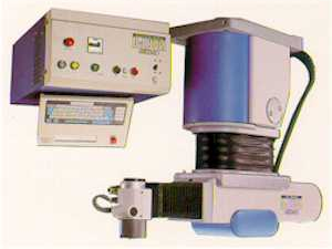
1 Seiko RT 3200 Extremely fast cycle time assures you higher throughout and increased productivity. Most powerful control system, insures quick system implementation and modular design and proven reliability make this robot very flexible and easy to service.
2
3

4

5 Seiko D-TRAN XY 3000
6 High speed, 4 axes, DC Servo, with simultaneous control. User-friendly DARL TM programming language. Configuration 4 Axes Payload (At maximum speed) 1 kg (2.2 lbs) Arm Range A: Grip Rotation ±900 deg. X: Horizontal Reach 300 mm (11.81 in.) Y: Horizontal Traverse 200 mm (7.87 in.) Z: Vertical Stroke 100 mm (3.94 in.) Speed A: Grip Rotation 7.5 rps (J = 2.0 gfcms 2 ) X: Horizontal Reach 1000 mm (40 in.) / sec Y: Horizontal Traverse 1000 mm (40 in.) / sec Z: Vertical Stroke 500 mm (20 in.) / sec Combined Maximum 1500 mm (59 in.) / sec Accuracy (XY-plane) mm ( in.) Repeatability ±0.008 mm ( in.) Resolution A: Grip Rotation deg. X: Horizontal Reach mm (0.0004) in. Y: Horizontal Traverse mm (0.0004) in. Z: Vertical Stroke mm (0.0004) in. Weight 105 kg (231 lbs)
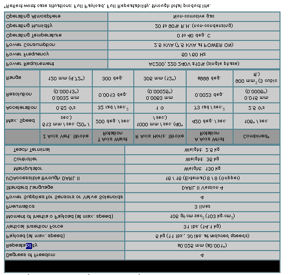
7 Degrees of Freedom 4 Repeatability ±0.025 mm (±0.001") Payload (at max. speed) 5 kg (11 lbs., 30 lbs. at reduced speeds) Vertical Insertion Force 31 lbs. (14.1 kg) Moment of Inertia o Payload (at max. speed) 105 gf cm sec 2 (103 kg cm 2 ) Pneumatics 3 lines Power Supplies for Sensors or Valve Solenoids 4 Standard Language DARL II Version 4 I/O Accessible through DARL II 16 / 16 (External) 8 / 8 (Gripper) Manipulator Weight: 130 kg Controller Weight: 35 kg Teach Terminal Weight: 2.5 kg

8

9 XYZ actuator

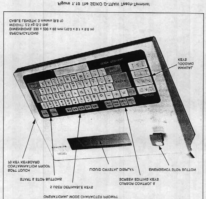
10 Seiko Pendant

11 Seiko D-Tran

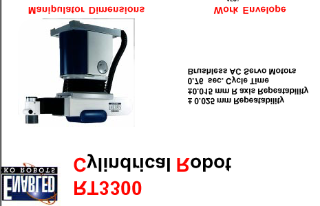
12 Cylindrical Robots Fast Cycle Time & High Repeatability 3rd Generation Design RT3200 Upgrades to RT3300 Powerful Controls Product Brochures CAD Drawings
13 Cylindrical Coordinate robots are a unique geometric design that has been highly refined by SEIKO. The RT3300 is hybrid mix which incorporates the rotary motion of the SCARA and the linear motion of a CARTESIAN. The Z axis is located inside the base, resulting in a compact end-ofarm design that allows the robot to "reach" into tight work envelopes without sacrificing speed or repeatability. Fast Cycle Time & High Repeatability The RT3300 has a standard cycle time of 0.8 seconds The R axis itself is comprised of a high quality rack and pinion gear design and is repeatable to mm. 3rd Generation Design The RT3300 is based on the proven design of the highly successful RT3200 robot. Using the same robust mechanics, this unit now incorporates AC Servo motors for reduced maintenance as well as the powerful SRC310A robot/workcell controller. All cables and pneumatic lines are neatly routed through the inside of the R axis, reducing wear and making for clean end of arm designs.
14 Upgrade Your RT3200 Robot to an RT3300 With an install base of several thousand units worldwide, the RT3200 has proven to be one of the world's most popular and durable robots. At SEIKO, we regularly rebuild older RT3200's for our customers and rewarranty them as new units. Now, with the introduction of the RT3300, our RT3200 users may upgrade their robots and benefit from both reduced maintenance and more powerful controls. Contact our Customer Service group at for more details. Powerful Control
15 Powerful Controls With our SRC-310A Controller and SPEL for Windows graphical user interface for development, Seiko has redefined the term easy to use. Many of our customers have experienced significant reductions in development time due to the ease with which our robots can be programmed.
16
17
18
19

20 The Seiko RT-3000 Work Cell
21 DARL Programming Manual OBJECTIVE: 1. Safety Considerations 2. Operation of the robot control 3. Startup and Shutdown Procedures 4. How to enter and edit a DARL program 5. How to teach the Translation Points in a DARL program 6. How to use the robot Input/Output signals for user defined purposes.
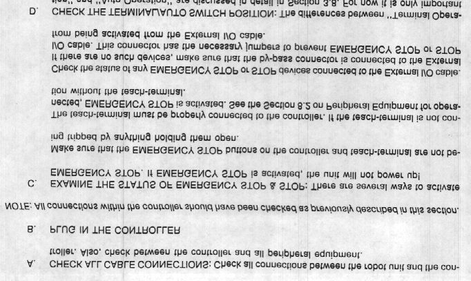
22 SAFETY NOTE: The robot can move very quickly and is capable of causing severe injury. When working around the robot keep in mind that the robot may move at unexpected times. Keep out of the robot work space if at all possible when the robot power is ON. NEVER-NEVER put your head into the robot work space. THINK ABOUT NO. 1 FIRST, namely yourself. The conveyor can cause injury also. Keep clear of the conveyor when it is operating. Don't get your clothing caught in the conveyor. Pneumatic actuators and grippers can exert considerable force. Keep your fingers out of grippers, lift stations, and other air operated devices. Do not probe the interior of the electrical equipment control enclosures when the power is ON. Some of these have high voltage signals which can cause injury.
23 INTRODUCTION: CAUTION: In the procedures to follow PLEASE PLEASE do not use the CALIB command. If not done properly this can cause considerable trouble and it will only delay your progress. Portions of the Seiko Robot Instruction Manual have been provided to each student. This will be referenced in portions of the experiment procedure. Review the pages from Chapter 1 of this manual. This will provide a general description and specifications of the robot. Note that the FAU robot installations include additional equipment not described in the Seiko manual.
24 INTRODUCTION: The purpose of this equipment is to provide the Input/Output (I/O) interface between the robot and the conveyor. It consists of: a: A Power Distribution Enclosure b. A System Interface Enclosure c. A Pneumatics Enclosure d. A Manual INPUT/OUTPUT Demonstration Box (I/ODB)
25 STARTUP PROCEDURE: Incorporating these Interface devices into the system requires some modification of the standard STARTUP procedure. This will introduce you to the operation of the Teach- Terminal and basic operations of the robot. Proceed as follows: 1. Turn on the Power Distribution Enclosure 2. Push the POWER ON button at the top of the door to the System Interface Enclosure 3. Push the SERVO ON button at the top of the door to the System Interface Enclosure. 4. Perform the operations provided in Chapter 3 of the Seiko Manual.
26 EDITING AND RUNNING A ROBOT DARL PROGRAM: The DARL language is very much like BASIC. It is easy to use and understand. It in fact includes some BASIC commands as well as robot commands like MOVE. Use the Teach-Terminal to enter the simple introduction program that follows. This program causes the robot to move to point 1 where it waits for a manual input signal to proceed. It then moves to point 2. At point 2 it turns on the vacuum gripper. It then moves to point 3 where it turns off the gripper, prints a message to the operator, waits for a second input and then repeats the process. This program has the basic elements of a PICK AND PLACE operation. It includes the DARL commands: Declarations of the coordinates of a TRANSLATION point. SPEED MOVE PRINT INPUT (From the Terminal) DELAY IF/THEN GOTO OUTPUT STOP END Comments
27 An explanation of these commands follows: (Refer to the program listing as you read this) In line 10 SPEED 20 sets the speed at which the robot moves. The syntax is SPEED <n>. n is a number from 1 to 300. The default value is 100, 1 is slow,300 is very fast. Use a slow speed when first checking out a new program. Locations of points where the robot is to move are called TRANSTATIONS. They are designated by T<n> where n is a number. TRANSLATIONS are defined near the start of a program. Lines 20,30, and 40 declare the three robot positions used in this program. The four numbers refer to the X Y Z and A coordinates of the point. Refer to page 9-16 in the Seiko Manual for details on entering and teaching TRANSLATION points.
28 Lines 10,20 etc include comments. Comments are for people not robots. Comments make the program more readable and easier to understand. The robot ignores the comments. Comments are introduced by an apostrophe. Note that lines 90 and 130 have no robot commands, only comments. Lines 50,110, and 150 are the move instructions. These cause the robot to move to the designated TRANSLATION points. Line 60 prints a message to the operator. This provides a method to program information to the operator. If used with the INPUT statement as in lines 70 and 200 it enables a method for any required operator interaction. For the INPUT command DARL interprets the ASCI value of the first letter of the INPUT response. In lines 70 and 200 if the input is Y the robot interprets the response as 89, the ASCI value for the letter Y.
29 Lines 80,100, and 210 include the GOTO command. It causes execution to continue at the indicated line number. In line 60 the output is intended for the operator. Line 120 is another form of robot output. It turns on the gripper.
30 The robot has provisions to control 16 separate devices such as the gripper. It can also receive signals from external devices such as sensors. External INPUT/OUTPUT (I/O) commands will be discussed in a subsequent section. The DELAY command is used in lines 140 and 170. The syntax is DELAY <n>. n is the time delay in milliseconds. The robot delays execution of the next command for the specified time. When the gripper is turned on in line 120 notice the time delay before moving to point T3. Line 240 causes the program to STOP. If the START button on the Teach-Terminal is subsequently pushed execution will continue at the next statement. PRINT in line 260 will verify START after STOP. END in line 280 stops execution and returns the Controller to MONITOR mode.
31 Line 120 turns ON the vacuum gripper while line 160 turns it OFF. This is a special I/O format for Model RT3000 and Model TT3000 robots due to a unique arrangement of the gripper control valve.
32 EXAMPLE PICK AND PLACE PROGRAM 10 SPEED 20 'Set the speed to a slow value for checkout 20 T 'Define the first point T1= T 'Define the second point T2= = T 'Define the third point T3= MOVE T1 'Move to point T1 60 PRINT "LINE 60" 70 INPUT "ENTER Y TO CONTINUE" S 80 IF S = 89 THEN GOTO '89 is the ASCI value for Y 100 GOTO 60 'Try again if S <> Y 110 MOVE T2 'move to point T2 120 OUTPUT +OG 'This turns on the vacuum gripper 140 DELAY 2000 'Delay 2 seconds 150 MOVE T3 'Move to the third TRANSLATION POINT 160 OUTPUT +OG1 250 'Turn off the gripper 170 DELAY 200 'Wait for the gripper to operate 180 PRINT "DID I DO OK?" 190 'Another message for the operator 200 INPUT "ENTER Y OR N" S 'Provide an operator response 210 IF S = 89 THEN GOTO 50 'Test the INPUT response 220 PRINT "I NEED TO REST" 240 STOP 'Push START to demonstrate 250 'START after STOP 260 PRINT "GOT TO LINE 260" 270 PRINT "THE END IS NEAR" 'No operator response required 280 END
33 Refer to the pages from Chapter 9 of the Seiko Manual and enter EDIT mode. TYPE NEW and then type in the example program. Try using the edit commands DELETE, NUMBER, RENUM, NUMBER L#,1, LIST and other editor commands described in Chapter 9. Return to MONITOR mode and then enter DISP. Refer to Chapter 9 for a description of the DISPLAY mode. Return to MONITOR mode and HOME the ROBOT.Now enter STEP. This is a debug mode for checking out new programs. Refer to Chapter 9 for details. Push START to execute each line of the example program. Use the editor to correct any program bugs.
34 Return to MONITOR mode and push START. THE robot will enter INTERPETER mode and execute the program. Enter responses as required. Demonstrate START after STOP and demonstrate entering N instead of Y when a response is requested. STOP the program and use the JOG keys and the HERE T<n> command to teach new points for the three TRANSLATIONS in the program. Refer to Chap. 9 for details. Use the editor to change the SPEED to 100 and execute the program again. Note the increase in speed.
35 INPUT/OUTPUT SIGNALS The Seiko robots include provisions for accepting input signals from external devices. The input signals take the form of switch closures. Typically they are generated by sensors such as mechanical switches, IR sensors, pressure switches, reflective sensors, etc. DARL programs can test these input signals and modify the robot operation according to the state of the signals. For example you might use a pressure switch to monitor the compressed air supply used to operate the gripper.
36 INPUT/OUTPUT SIGNALS If the air pressure were too low the gripper might not operate. In that case you would want the program to stop and wait until the air pressure was adequate. This is easily programmed if the input signal is provided. You might also use a sensor and input signal to determine if the part feeder was empty.
37 In a similar manner the robot can provide OUTPUT signals to control external devices such as grippers, conveyor lift stations, part feeders etc. The output signals also take the form of switch closures. The operation of the OUTPUT signals is controlled by the robot program.
38 The robot has a capability for accepting 16 INPUT signals through the EXTERNAL I/O connector. It can also accept 8 INPUT signals through the GRIPPER CABLE. It can generate 16 OUTPUT signals through the EXTERNAL I/O connector and 8 more through the GRIPPER CABLE. The GRIPPER CABLE is routed directly to the robot end of arm hence I/O signals routed through the GRIPPER CABLE are intended for operation of devices attached in this area. The signals routed through the EXTERNAL I/O connector are intended for devices not attached to the robot such as part feeders, air control valves, conveyor systems and similar.
39 Chapter 5 of the Seiko Manual provides a detailed description of the I/O signals and the DARL statements associated with them. Review that material before proceeding. The robots which you will be using have three OUTPUT signals connected to operate the conveyor system. The gripper OUTPUT signal controls an air valve which routes compressed air to a vacuum generator used to provide suction at the gripper.
40 The conveyor OUTPUT signals are as follows: One signal controls an air cylinder which lifts the pallet off the conveyor and locks the pallet in a fixed position so the robot can place a part on the pallet. This device is called a lift station. A second signal operates a STOP device at the lift station. The STOP is used to stop or release a pallet over the lift station. The third OUTPUT signal controls a similar STOP upstream from the lift station. This is called the QUE STOP. It is used to control flow of pallets to the lift station. All of these signals are permanently connected to the robot controller through the System Interface Enclosure.
41 It is possible to connect other devices into the System Interface. A small I/O Demonstration Box (I/ODB) is provided to demonstrate how I/O signals are connected and programmed. The I/ODB has 4 red LED which responds to robot OUTPUT signals. It has 4 manually operated switches which can be connected as an input devices. The circuit diagram for the I/ODB is shown in the Figure 1.
42 Turn Off the power at the Power Distribution Enclosure. Connect four wires to terminals in the System Interface Enclosure. The red wire is to be connected to a +24V DC terminal. The black wire is to be connected to GND. The system Interface Enclosure terminals and LED display are illustrated on the attached drawings. Your instructor will assist you with the details. Have your instructor inspect the connections before turning ON the power. Figure 1: I/O Demonstration Box.
43 Turn On the robot using the startup procedure. In Monitor mode: 1. Type DO OUTPUT +OE0. This should turn on the red LED in the I/ODB. Also note that the terminal panel in the back of the System I/O Interface Enclosure has LED indicators at each I/O terminal. The LED at the panel terminal OE0 should also be ON. 2. Now type DO OUTPUT -OE0. This should turn off the both LEDs. 3. Turn off the switch on the I/ODB. 4. Type DO A = INPUT IE0. 5. Then type DO PRINT "A=";A. The Terminal should display A = 0.
44 Enter DISP mode and note the state of all I/O channels as described in Chapter 9. Also note the LED at the I/O Interface Panel IE0.
45 Now turn on the switch on the I/ODB. Note the LED on the Interface Panel Terminal IE0. Again use DISP mode to determine the state of all I/O channels. Use the editor to type the small program below. 10 B = 0 20 OUTPUT -OE0 30 A = INPUT IE0 40 IF B = A THEN GOTO B = A 60 IF B = 1 THEN GOTO GOTO OUTPUT +OE0 90 GOTO 30
46 Execute the program. Turn the switch on the I/ODB off and on several times. Does the program perform as you expect? This little program demonstrates the ability of a DARL program to respond to and control I/O signals. In Monitor mode: 1. Type DO OUTPUT +OE5. Expect the lift station to operate. 2. Type DO OUTPUT -OE5. The lift station should retract. 3. Type DO OUTPUT +OE4. This should operate the lift station STOP. 4. Type DO OUTPUT -OE4. The lift station STOP should reset. 5. Type DO OUTPUT +OE3 and then DO OUTPUT -OE3. This should operate the QUE STOP.
47 Place pallets over the sensor for the lift station, the QUE sensor, and the down stream sensor. Observe the LEDs on the System Interface Enclosure panel. The LEDs associated with IE1, IE2,and IE3 should all be OFF. Use the DISP mode to determine the state of all I/O channels. Remove the pallets from the sensors and repeat the observations.
48 Figure 1: Box connections.

49 Figure 2: Interface box.

50 Figure 2: Interface box.

51 Figure 3: Interface box.

52 Figure 4: Power supply connections

53
54

55

56

57

58 Figure 5: The teach terminal

59
60

61

62 Figure 6:Basic operations

63

64

65

66

67
68 Figure 7:Programmable function keys.
69 Figure 8: Jogging the robot.

70 Figure 9:Homing the robot.
71
72

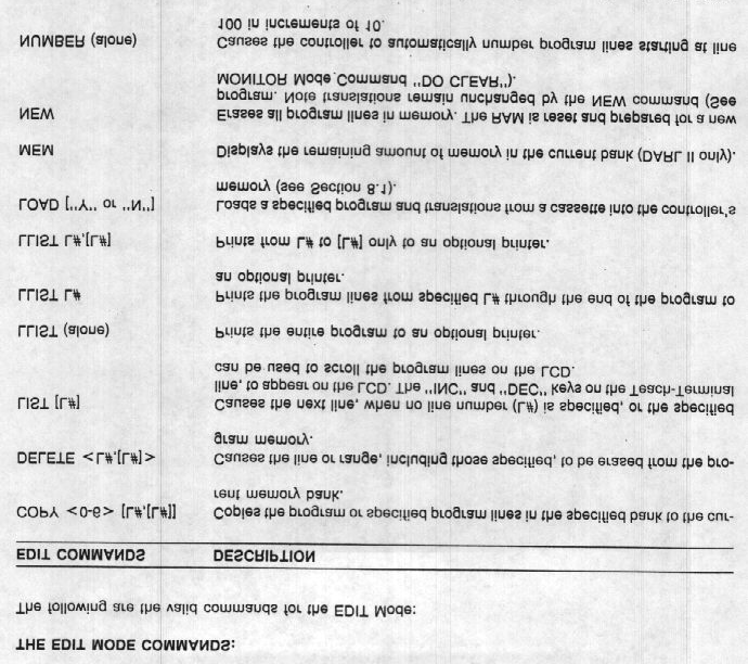
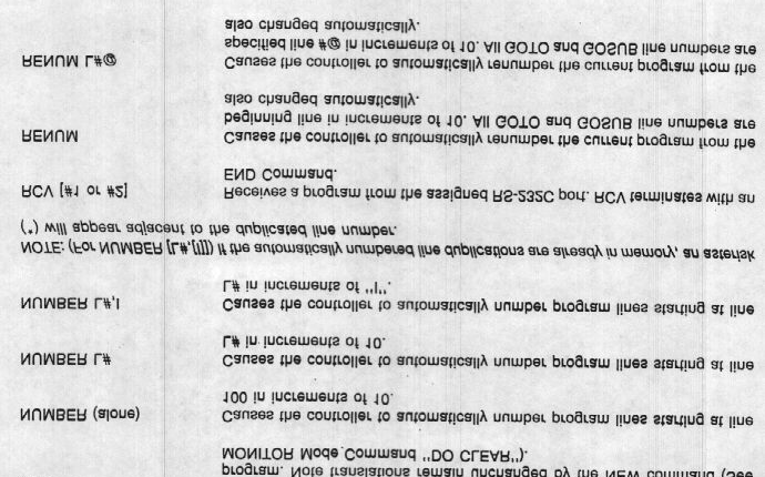
73 Figure 10: Edit mode commands.
CIM Computer Integrated Manufacturing
 INDEX CIM IN BASIC CONFIGURATION CIM IN ADVANCED CONFIGURATION CIM IN COMPLETE CONFIGURATION DL CIM A DL CIM B DL CIM C DL CIM C DL CIM B DL CIM A Computer Integrated Manufacturing (CIM) is a method of
The modular Line and Room Gantry design from SCHUNK
 The modular Line and Room Gantry design from SCHUNK Save up to 50% Exceptional precision from the competence leader for clamping technology and gripping systems Standard Gantries ready for assembly, at
Robotics and Automation Blueprint
 Robotics and Automation Blueprint This Blueprint contains the subject matter content of this Skill Connect Assessment. This Blueprint does NOT contain the information one would need to fully prepare for
Industrial Robotics. Training Objective
 Training Objective After watching the program and reviewing this printed material, the viewer will learn the basics of industrial robot technology and how robots are used in a variety of manufacturing
How to read this guide
 How to read this guide The following shows the symbols used in this Quick start guide with descriptions and examples. Symbol Description Example P oint Reference Caution [ ] This symbol explains information
Selecting Robots for Use in Drug Discovery and Testing
 Selecting Robots for Use in Drug Discovery and Testing What Are the Essential Things to Know? Drug discovery and testing, with their need for speed, repeatability and verification, are ideally suited to
FUNDAMENTALS OF ROBOTICS
 FUNDAMENTALS OF ROBOTICS Lab exercise Stäubli AULINAS Josep (u1043469) GARCIA Frederic (u1038431) Introduction The aim of this tutorial is to give a brief overview on the Stäubli Robot System describing
Servo Motors (SensorDAQ only) Evaluation copy. Vernier Digital Control Unit (DCU) LabQuest or LabPro power supply
 Evaluation copy. Vernier Digital Control Unit (DCU) LabQuest or LabPro power supply") Servo Motors (SensorDAQ only) Project 7 Servos are small, relatively inexpensive motors known for their ability to provide a large torque or turning force. They draw current proportional to the mechanical
Servo Motors (SensorDAQ only) Project 7 Servos are small, relatively inexpensive motors known for their ability to provide a large torque or turning force. They draw current proportional to the mechanical
Six-servo Robot Arm. DAGU Hi-Tech Electronic Co., LTD www.arexx.com.cn. Six-servo Robot Arm
 Six-servo Robot Arm 1 1, Introduction 1.1, Function Briefing Servo robot, as the name suggests, is the six servo motor-driven robot arm. Since the arm has a few joints, we can imagine, our human arm, in
OPL BASIC. Dosing System for Professional Laundry machines. Contents
 OPL BASIC Dosing System for Professional Laundry machines Contents 1 Getting Started. Page 2 2 Installation. Page 4 3 Set Up & Operation. Page 8 4 Maintenance & Accessories. Page 10 5 Troubleshooting Page
Industrial robots. SCARA robots for industrial applications.»» Reliable and versatile»»simple programming and quick set-up»»economical and efficient
 Industrial robots SCARA robots for industrial applications»» Reliable and versatile»»simple programming and quick set-up»»economical and efficient A win-win mechatronics proposition Your benefits: Simplify
ERC-to-MRC JOB TRANSLATOR MANUAL
 Yasnac MRC Controller ERC-to-MRC JOB TRANSLATOR MANUAL Part Number 133110-1 Yasnac MRC Controller ERC-to-MRC Job Translator Manual Part Number 133110-1 June 13, 1995 MOTOMAN 805 Liberty Lane West Carrollton,
EasyC. Programming Tips
 EasyC Programming Tips PART 1: EASYC PROGRAMMING ENVIRONMENT The EasyC package is an integrated development environment for creating C Programs and loading them to run on the Vex Control System. Its Opening
SCARA ROBOT TH SERIES
 Wide Variations, Fast Motion, and Heavy Duty SCARA ROBOT TH SERIES Compact SCARA Robot High-Speed and High-Precision SCARA Robot High Payload Mass SCARA Robot TH180, TH250A, TH350A TH450, TH550 TH650A,
5 WAYS TO EVEN GREATER EFFICIENCY
 EPSON PROSIX C4 AND C8 SERIES 6 AXIS ROBOTS 5 WAYS TO EVEN GREATER EFFICIENCY ENGINEERED FOR BUSINESS 2 / 3 / THE OPTIMAL FAMILY PACKAGE DIFFERENT RANGES, VARIOUS LOAD CAPACITIES You don t want a standard
Stirling Paatz of robot integrators Barr & Paatz describes the anatomy of an industrial robot.
 Ref BP128 Anatomy Of A Robot Stirling Paatz of robot integrators Barr & Paatz describes the anatomy of an industrial robot. The term robot stems from the Czech word robota, which translates roughly as
Ecopaint Robot Painting Station
 Ecopaint Robot Painting Station Newest Generation of EcoRP Painting Robots Technologies Systems Solutions Ecopaint Robot Painting Station The Basis for Shining Results Exterior painting Ecopaint Robot
PRODUCTIVITY THROUGH INNOVATION 600 CONTROL DIRECT DRIVE TECHNICAL/OPERATION MANUAL
 Rev. D PRODUCTIVITY THROUGH INNOVATION 600 CONTROL DIRECT DRIVE TECHNICAL/OPERATION MANUAL 10 BORIGHT AVENUE, KENILWORTH NEW JERSEY 07033 TELEPHONE: 800-524-0273 FAX: 908-686-9317 TABLE OF CONTENTS Page
Programming Logic controllers
 Programming Logic controllers Programmable Logic Controller (PLC) is a microprocessor based system that uses programmable memory to store instructions and implement functions such as logic, sequencing,
Learning Systems Software Simulation
 Learning Systems Software Simulation EasyVeep PLC controls and technology training FluidSIM Fluid Power training aid for instructors and design tool for engineers COSIMIR PLC 3D simulation tool for practical
5. Tutorial. Starting FlashCut CNC
 FlashCut CNC Section 5 Tutorial 259 5. Tutorial Starting FlashCut CNC To start FlashCut CNC, click on the Start button, select Programs, select FlashCut CNC 4, then select the FlashCut CNC 4 icon. A dialog
Programmable Logic Controllers Definition. Programmable Logic Controllers History
 Definition A digitally operated electronic apparatus which uses a programmable memory for the internal storage of instructions for implementing specific functions such as logic, sequencing, timing, counting,
Phil Crowther, Product Management, April 2015 YuMi IRB 14000 Overview
 Phil Crowther, Product Management, April 2015 YuMi IRB 14000 Overview YuMi: IRB 14000 Agenda Differentiated value proposition Overview and vision Main features Payload Working range Performance and accuracy
PALLETS ROLLER CONVEYOR LOADING CONVEYOR CHAIN TRANSFER TURNTABLE ROLLER STOP
 AUGUST 12, 2014 INDEX 04 07 04 06 EMITTER REMOVER 07 08 10 12 14 BOXES BELT CONVEYOR BELT CONVEYOR GATE STRAIGHT SPUR CONVEYOR CONVEYOR SCALE 16 17 18 19 20 22 24 26 ALIGNERS WHEEL ALIGNER BRACKET CHUTE
Industrial Robot Technology
 Unit 132: Industrial Robot Technology Unit code: Y/602/5130 QCF Level 3: BTEC Nationals Credit value: 10 Guided learning hours: 60 Aim and purpose This unit will develop learners understanding of the operation
1. EXTERNAL ALARM MESSAGE
 . EXTERAL ALARM MESSAGE 00 SAFET DOOR EED CLOSE! ALARM 00 Is the safety door closed? Close the safety door. Is the window closed? Close the window. The diagnostic X8.=0. The limit switch (-A27) for the
Proximity Switches RS (Reed Switch)
") Proximity Switches RS (Reed Switch) General Pneumatic systems can often be combined with electric control circuits. The position of the piston in the cylinder can then be sensed by means of a proximity
Proximity Switches RS (Reed Switch) General Pneumatic systems can often be combined with electric control circuits. The position of the piston in the cylinder can then be sensed by means of a proximity
MINIMAT-EC-Servo Screwdriver Spindles
 Screwdriving technology Automation Air motors Air tools Screwdriver Spindles electric MINIMAT-EC-Servo Screwdriver Spindles Maximum Flexibility and process Control Straight Spindle Form - Torque range
INTRODUCTION TO SERIAL ARM
 INTRODUCTION TO SERIAL ARM A robot manipulator consists of links connected by joints. The links of the manipulator can be considered to form a kinematic chain. The business end of the kinematic chain of
Standard Cables (Without electromagnetic brake, with electromagnetic brake) CC010ES-2. 1 m CC020ES-2. 2 m CC030ES-2. 3 m CC050ES-2.
 CC010ES-2. 1 m CC020ES-2. 2 m CC030ES-2. 3 m CC050ES-2.") Motorized Actuators Motor Cables EZS /EZS for Clean Room Use This cable is a dedicated cable for connecting the linear slide of the EZS Series and EZS Series for Clean Room Use with the controller. Use
Motorized Actuators Motor Cables EZS /EZS for Clean Room Use This cable is a dedicated cable for connecting the linear slide of the EZS Series and EZS Series for Clean Room Use with the controller. Use
1115 4G SERIES GOVERNOR. 4-20 ma ANALOGUE DIGITAL SPEED SETTING
 1115 4G SERIES GOVERNOR with 4-20 ma ANALOGUE & DIGITAL SPEED SETTING PO Box 28, 9300AA Roden, The Netherlands Tel: +31 505019888 Fax: +31 505013618 E-mail: [email protected] 1115 4G
ETZGAR CONVEYOR COMPANY Controls Section v12.05
 Section 7 Controls Page Description 7-1 Controls Index 7-2 Motor Data, Enclosure Rating and Abbreviations 7-3 Controls Safety Guidelines 7-4 Fixed Speed Controls Packages 7-5 Three Phase AC Variable Speed
Robot soldering head 4900
 Robot soldering head 4900 Subject to technical changes 09/10 Application/use (example) - Soldering all contacts - Automotive (3-shift operation) Technical specifications: - Bit soldering technique or resistance
Bluetooth + USB 16 Servo Controller [RKI-1005 & RKI-1205]
![Bluetooth + USB 16 Servo Controller [RKI-1005 & RKI-1205]](/thumbs/40/21161302.jpg "Bluetooth + USB 16 Servo Controller [RKI-1005 & RKI-1205]") Bluetooth + USB 16 Servo Controller [RKI-1005 & RKI-1205] Users Manual Robokits India [email protected] http://www.robokitsworld.com Page 1 Bluetooth + USB 16 Servo Controller is used to control up to
Bluetooth + USB 16 Servo Controller [RKI-1005 & RKI-1205] Users Manual Robokits India [email protected] http://www.robokitsworld.com Page 1 Bluetooth + USB 16 Servo Controller is used to control up to
Operation Manual. Plasma torch height controller. Model: Compact THC Controller 150
 Operation Manual Plasma torch height controller. Model: Compact THC Controller 150 Notes on safety WHEN THE DEVICE IS IN OPERATION, VOLTAGE HAZARDOUS TO HEALTH AND HUMAN LIFE IS PRESENT INSIDE THE HOUSING
A-9. Chapter 2. Material flow. Chapter 2. Festo Didactic Mechatronics
 A-9 Material flow Festo Didactic Mechatronics A-10 2.1 General 2.1.1 Definition of terms Material flow is the linking of all processes for the acquiring, processing, machining and distribution of material
GANTRY ROBOTIC CELL FOR AUTOMATIC STORAGE AND RETREIVAL SYSTEM
 Advances in Production Engineering & Management 4 (2009) 4, 255-262 ISSN 1854-6250 Technical paper GANTRY ROBOTIC CELL FOR AUTOMATIC STORAGE AND RETREIVAL SYSTEM Ata, A., A.*; Elaryan, M.**; Gemaee, M.**;
Evaluation copy. Blood Pressure. Project PROJECT DESIGN REQUIREMENTS
 Blood Pressure Project 9 Blood pressure is a measure of the fluid pressure within the circulatory system. This pressure is required to ensure the delivery of oxygen and nutrients to, and the removal of
UNIT II Robots Drive Systems and End Effectors Part-A Questions
 UNIT II Robots Drive Systems and End Effectors Part-A Questions 1. Define End effector. End effector is a device that is attached to the end of the wrist arm to perform specific task. 2. Give some examples
AEO Head Movement Tracker X-GYRO 1000 USER MANUAL(V1.1bata 20091019)
") AEO Head Movement Tracker X-GYRO 1000 USER MANUAL(V1.1bata 20091019) Introduction: X-GYRO 1000 is a two axis head tracking system, based on G sensor technique, designed for tracking complicated three-dimensional
AEO Head Movement Tracker X-GYRO 1000 USER MANUAL(V1.1bata 20091019) Introduction: X-GYRO 1000 is a two axis head tracking system, based on G sensor technique, designed for tracking complicated three-dimensional
E/P Regulator (DeviceNet TM type) ITV1000/2000/3000/2090-DE* Series
 ITV1000/2000/3000/2090-DE* Series") Doc. No. ITV2-OM00095-B P R O D U C T N A M E E/P Regulator (DeviceNet TM type) MODEL/ Series/ Product Number ITV1000/2000/3000/2090-DE* Series Install and operate the product only after reading the Operation
Doc. No. ITV2-OM00095-B P R O D U C T N A M E E/P Regulator (DeviceNet TM type) MODEL/ Series/ Product Number ITV1000/2000/3000/2090-DE* Series Install and operate the product only after reading the Operation
PLC Based Liquid Filling and Mixing
 PLC Based Liquid Filling and Mixing 1 Mihir Panchal, 2 Aashish Panaskar. 3 Prof. Lalit Kumar KJ College of Engineering and Management Research, Pune, India Abstract: The objective of this paper is to design,
IRB 2600ID-15/1.85 Simple integration, high performance
 Per Lowgren, Product Manager, Medium robots IRB 2600ID-15/1.85 Simple integration, high performance February 9, 2011 Slide 1 Overview of main features General purpose robot for integrated dressing solutions.
How To Run A Factory I/O On A Microsoft Gpu 2.5 (Sdk) On A Computer Or Microsoft Powerbook 2.3 (Powerpoint) On An Android Computer Or Macbook 2 (Powerstation) On
 On A Computer Or Microsoft Powerbook 2.3 (Powerpoint) On An Android Computer Or Macbook 2 (Powerstation) On") User Guide November 19, 2014 Contents 3 Welcome 3 What Is FACTORY I/O 3 How Does It Work 4 I/O Drivers: Connecting To External Technologies 5 System Requirements 6 Run Mode And Edit Mode 7 Controls 8 Cameras
User Guide November 19, 2014 Contents 3 Welcome 3 What Is FACTORY I/O 3 How Does It Work 4 I/O Drivers: Connecting To External Technologies 5 System Requirements 6 Run Mode And Edit Mode 7 Controls 8 Cameras
Chapter 2 Fundamentals of Robotics
 This sample chapter is for review purposes only. Copyright The Goodheart-Willcox Co., Inc. All rights reserved. Chapter 2 Fundamentals of Robotics Chapter Topics 2.1 Parts of a Robot 2.2 Degrees of Freedom
A descriptive definition of valve actuators
 A descriptive definition of valve actuators Abstract A valve actuator is any device that utilizes a source of power to operate a valve. This source of power can be a human being working a manual gearbox
GPD 506/P5 Start-up Procedure and Checklist
 GPD 506/P5 Start-up Procedure and Checklist Preparation for GPD506/P5 Drive Start-Up...2 HVAC Start-Up Procedure for GPD 506/P5 WITH Bypass Option:...4 HVAC Start-Up Procedure for GPD 506/P5 WITHOUT Bypass
Stop Alert Flasher with G-Force sensor
 Stop Alert Flasher with G-Force sensor Stop Alert module creates brake light flashing effect to catch attention of the drivers behind to avoid dangerous rear end collision. The flasher module is a state
Lab 4 - Data Acquisition
 Spring 11 Lab 4 - Data Acquisition Lab 4-1 Lab 4 - Data Acquisition Format This lab will be conducted during your regularly scheduled lab time in a group format. Each student is responsible for learning
Instruction Manual. This Manual covers the use of: SmartSwitch Servo Kit. DCC Stationary Decoder PLEASE READ THESE INSTRUCTIONS FULLY BEFORE USE
 built by Instruction Manual This Manual covers the use of: PLS-125 PLS-130 PLS-135 SmartSwitch Servo Kit SmartFrog DCC Stationary Decoder PLEASE READ THESE INSTRUCTIONS FULLY BEFORE USE Contents Introduction
Robotics. Dispensing Automation
 Robotics Dispensing Automation Index 1 Introducing Advances in Robotics 2-5 F7000N Optima Series Benchtop Robots F7300N 3 & 4 Axes 300 x 300mm Work Area F7400N 3 & 4 Axes 400 x 400mm Work Area F7000NV
ECE 495 Project 3: Shocker Actuator Subsystem and Website Design. Group 1: One Awesome Engineering
 ECE 495 Project 3: Shocker Actuator Subsystem and Website Design Group 1: One Awesome Engineering Luquita Edwards Evan Whetsell Sunny Verma Thomas Ryan Willis Long I. Executive Summary The main goal behind
OPERATION MANUAL VALVE CHECKER G040-123
 OPERATION MANUAL VALVE CHECKER AUSTRALIA PTY. LTD. L:\DWG_NO\DOCUMENT\MANUALS\Word File\A OPERATION MANUAL CN 20.4.99 VALVE CHECKER 1 of 20 CONTENTS Chapter Title Page 1. Description 3 2. Specification
Learning Systems Modular Systems for Mechatronics Training
 Learning Systems Modular Systems for Mechatronics Training MPS Modular Production System Model industrial automation systems at various levels of complexity MPS Combinations Model specific combinations
RIA : 2013 Market Trends Webinar Series
 RIA : 2013 Market Trends Webinar Series Robotic Industries Association A market trends education Available at no cost to audience Watch live or archived webinars anytime Learn about the latest innovations
Loctite RB15 200D Gantry Robot. Equipment. Operation Manual. Part Number:1670898. Operation Manual RB15 200D. Gantry Robot. Item No.
 PURGE Pow er START PROG NO. RUN TEACH ER M E ST Teach Pendant R S 232 Henkel AG & Co. KGaA Standort München Gut enbergstr. 3 D-85748 Garching Loctite RB15 200D Gantry Robot, 24V Item No. 1670898 Serial
Computer Controlled Generating Stations Control and Regulation Simulator, with SCADA SCE
 Technical Teaching Equipment Computer Controlled Generating Stations Control and Regulation Simulator, with SCADA SCE EDIBON SCADA System Teaching Technique used 4 5 2 Data Acquisition Board Cables and
The Department of Engineering, has two Scorbot-ER VII robotic manipulators and one Controller- A. There are 4 components in the system:
 Introduction to the Scorbot ER VII and the Eshed Robotec Pty. Ltd. Advanced Control Language (ACL) Robert MAHONY, Dep. Engineering, ANU, ACT, 0200, Australia. The Department of Engineering, has two Scorbot-ER
Robotic Collision Sensor and/ Axial Compliance Device Protector
 NEW 2005 CATALOG Robotic Collision Sensor and/ Axial Compliance Device Protector PROTECTOR Product Description The Protector is a collision sensor, or crash protection device, designed to prevent costly
D-MAX WEB GUIDE CONTROLLER WITH OPERATOR INTERFACE PANEL QUICK START SETUP MANUAL
 1/1 D-MAX.D1 1A Manual S1 D-MAX OPERATOR INTERFACE (Application Home Screen Is Shown) D-MAX CONTROLLER 04/14/2008 2008 Fife Corporation. All rights reserved. Figure Sheet 2-249 This page is intentionally
Unit 24: Applications of Pneumatics and Hydraulics
 Unit 24: Applications of Pneumatics and Hydraulics Unit code: J/601/1496 QCF level: 4 Credit value: 15 OUTCOME 2 TUTORIAL 4 DIRECTIONAL CONTROL VALVES The material needed for outcome 2 is very extensive
Introduction. Drenth Motorsport Gearboxes Fleuweweg 10 7468 AG Enter The Netherlands Phone: +31 (0)547 38 26 96 Fax: +31 (0)547 38 20 65
547 38 26 96 Fax: +31 (0)547 38 20 65") 25.03.0023 Introduction The display comes with a software application. With the software application information shown on the display can be adjusted. There are different modes to adjust: the shape of
25.03.0023 Introduction The display comes with a software application. With the software application information shown on the display can be adjusted. There are different modes to adjust: the shape of
Design Aspects of Robot Manipulators
 Design Aspects of Robot Manipulators Dr. Rohan Munasinghe Dept of Electronic and Telecommunication Engineering University of Moratuwa System elements Manipulator (+ proprioceptive sensors) End-effector
Congratulations for making the decision to become one of the many proud KT-X robot owners.
 Congratulations for making the decision to become one of the many proud KT-X robot owners. The following quick start guide will enable to get your KT-X up and running in as little time as possible. Before
BLE Series. Data setting software MEXE02 OPERATING MANUAL. Tabel of contents 1 Synchronization with the driver...2 2 Monitor function...
 HP-5046 Data setting software MEXE02 BLE Series OPERATING MANUAL Thank you for purchasing an Oriental Motor product. This operating manual describes product handling procedures and safety precautions.
Siemens AG 2011 SINAMICS V60. The perfect solution for basic servo applications. Brochure May 2011 SINAMICS. Answers for industry.
 The perfect solution for basic servo applications Brochure May 2011 SINAMICS Answers for industry. with 1FL5 servomotors The solution for basic servo applications There is a requirement to automate motion
SuperIOr Controller. Digital Dynamics, Inc., 2014 All Rights Reserved. Patent Pending. Rev: 5-16-14 1
 SuperIOr Controller The SuperIOr Controller is a game changer in the world of high speed embedded control. The system combines incredible speed of both control and communication with revolutionary configurable
Manual for Fire Suppression & Methane Detection System
 Manual for Fire Suppression & Methane Detection System Fogmaker North America Post address: 150 Gordon Dr Exton, PA 19341 Delivery address: 150 Gordon Dr Exton, PA 19341 Tel: 610-265-3610 Fax: 610-265-8327
e-4 AWT07MLED 7 Q TFT LCD MONITOR (LED Backlighted) USER MANUAL
 USER MANUAL") Thank you for purchasing our product. Please read this User s Manual before using the product. Change without Notice AWT07MLED 7 Q TFT LCD MONITOR (LED Backlighted) USER MANUAL e-4 SAFETY PRECAUTIONS Federal
Thank you for purchasing our product. Please read this User s Manual before using the product. Change without Notice AWT07MLED 7 Q TFT LCD MONITOR (LED Backlighted) USER MANUAL e-4 SAFETY PRECAUTIONS Federal
COIL PAC. Subec AB, Sprängarvägen 16, 132 38 Saltsjö-Boo, Sweden, Tel.: +46 8 884633, Fax: +46 8 977658, e-mail: [email protected]
 COIL PAC Subec AB, Sprängarvägen 16, 132 38 Saltsjö-Boo, Sweden, Tel.: +46 8 884633, Fax: +46 8 977658, e-mail: [email protected] Description of the machine Coil Pac 240 und Coil Pac 400 are two types of
Selecting and Sizing Ball Screw Drives
 Selecting and Sizing Ball Screw Drives Jeff G. Johnson, Product Engineer Thomson Industries, Inc. Wood Dale, IL 540-633-3549 www.thomsonlinear.com [email protected] Fig 1: Ball screw drive is a
SECTION G2: CABLE PROCESSOR MODULE MAINTENANCE
 SECTION G2: CABLE PROCESSOR MODULE MAINTENANCE Cable Processor Module overview WARNING! When tipping the Cable Processor Module back, (after removing the toggle arm pin), use extreme caution not to drop
Servo Info and Centering
 Info and Centering A servo is a mechanical motorized device that can be instructed to move the output shaft attached to a servo wheel or arm to a specified position. Inside the servo box is a DC motor
The RIDZ 8x2 Audio Switcher
 The RIDZ 8x2 Audio Switcher Engineering Manual Support Number 800-765-2930 International 712-852-2813 Table of Contents General Information for the RIDZ (8 x 2) Switcher..... 3 Input 9 on the RIDZ Switcher....6
INSTALLATION INSTRUCTIONS
 LIGHTING CONTROL PANELS 4 AND 8 RELAYS INSTALLATION INSTRUCTIONS INSTALLATION OVERVIEW The installation instructions contained in this document are provided as a guide for proper and reliable installation.
GSM Gate Opener GSM Remote Switch RTU5015 User Manual
 GSM Gate, Barrier, Shutter, Garage Door and Door opener Open gate or garage door with a FREE call from your mobile phone! Remote switching machines with a FREE call from your mobile phone! GSM Gate Opener
Computer Integrated Manufacturing Applications
 Mechatronics Computer Integrated Manufacturing Applications Courseware Sample 39468-F0 Order no.: 39468-00 First Edition Revision level: 02/2015 By the staff of Festo Didactic Festo Didactic Ltée/Ltd,
OCSM Series. High Resolution Digital Crane Scale. User Guide
 OCSM Series High Resolution Digital Crane Scale Content 1. Safety Guide... 1 2. Features... 1 3. Specifications... 2 4. Capacity... 3 5. Display & Keys... 3 Scale & Remote Keys... 3 Indicators... 4 Message...
Background: Experimental Manufacturing Cell
 Session 3548 A WEB-BASED APPROACH TO AUTOMATED INSPECTION AND QUALITY CONTROL OF MANUFACTURED PARTS Immanuel Edinbarough, Manian Ramkumar, Karthik Soundararajan The University of Texas at Brownsville/Rochester
APPENDIX. SureSERVO QUICK START GUIDE. In This Appendix... Quick Start for SureServo Drives...A 2. Tuning Quick Start for SureServo Drives...
 SureSERVO QUICK START GUIDE APPENDIX BA In This Appendix... Quick Start for SureServo Drives.............A 2 Spin the Motor......................................A 2 Position Mode Quick Start (Pt & Pr)......................A
TBG-25 OPTIONS X AXIS TRAVEL (MM) Z AXIS TRAVEL (MM) OPTIONS FOR: SPECIFICATIONS. Specifications. Configuration. Belt Type 25.
 Z AXIS TRAVEL (MM) OPTIONS FOR: SPECIFICATIONS. Specifications. Configuration. Belt Type 25.") LINEAR ROBOTICS > T-BOT GANTRY ROBOTS T-BOT GANTRY ROBOTS TBG-25 OPTIONS X AXIS TRAVEL (MM) 500 1000 2000 Custom Z AXIS TRAVEL (MM) 250 500 Custom Controls Motor Gearbox HOW TO BUILD YOUR TBG-25: Features
LINEAR ROBOTICS > T-BOT GANTRY ROBOTS T-BOT GANTRY ROBOTS TBG-25 OPTIONS X AXIS TRAVEL (MM) 500 1000 2000 Custom Z AXIS TRAVEL (MM) 250 500 Custom Controls Motor Gearbox HOW TO BUILD YOUR TBG-25: Features
POINTS POSITION INDICATOR PPI4
 POINTS POSITION INDICATOR PPI4 Advanced PPI with Adjustable Brightness & Simplified Wiring Monitors the brief positive operating voltage across points motors when they are switched Lights a corresponding
NM i Automasjon 2014 Project 4:
 NM i Automasjon 2014 Project 4: Project 4 - Optimizing of Distribution and Turnover station Weighting (Points out of total) 15/100 Maximum time 60 minutes Task: Your task is to optimize a finished production
Windshield Wiper Motors
 Windshield Wiper Motors Originally posted by Dan Masters, [email protected] Also see http://www.advanceautowire.com/ WIPER OPERATION: There are three major components to a wiper motor: Motor Rotary to linear
Product Information Sheet UH36 Hi Pot Tester
 Product Information Sheet UH36 ETL Prüftechnik GmbH Telefon: +49 711 83 99 39-0 E-Mail: [email protected] Carl-Peters-Straße 23 D-70825 Korntal-Münchingen Telefax: +49 711 83 99 39-9 Internet: www.etl-prueftechnik.de
MET 306. Activity 8a. Mechanism Design Creo 2.0 Level 7 POINT A GROUND LINK LINK 1 LINK 2 LINK 3 POINT B 10/15/2010 1
 Mechanism Design Creo 2.0 Level 7 POINT A LINK 1 GROUND LINK LINK 2 LINK 3 POINT B 10/15/2010 1 Download parts ground, key, link_1, link_2, link_3 and pulley from the V:/MET_306/Activity_8_Creo drive.
NetScanner System. Toronto: 416 754 7008, Montreal: 514 695 5147, Toll Free:1888 754 7008, Email: [email protected]; www.a-tech.ca
 Networking Solutions NetScanner System 9IFC/90DB/90DC FEATURES Ethernet Interface for NetScanner System Modules Provides Power and Hardware Trigger Interface 10/100 Base-T Auto-Negotiating Universal AC
B/S/H/ Error codes and service programmes PH
 1 ERROR CODES AND APPLIANCE MESSAGES... 3 1.1 Complete overview of all error codes (in order)... 3 Automatic switch-off... 3 Display is dark and any individual LEDs are lit... 3 E 005... 3 E 011... 3 E
Points Position Indicator (PPI1) for Points Motors with Common Ground
 for Points Motors with Common Ground") Points Position Indicator (PPI1) for Points Motors with Common Ground Monitors Points Action and Operates Leds on a Control Panel Monitors the brief positive operating voltage across points motors when
Points Position Indicator (PPI1) for Points Motors with Common Ground Monitors Points Action and Operates Leds on a Control Panel Monitors the brief positive operating voltage across points motors when
USER MANUAL. EZRUN Series Brushless Speed Controller EZRUN-150A-PRO
 USER MANUAL EZRUN Series Brushless Speed Controller EZRUN-150A-PRO User Manual of EZRUN-150A-PRO Brushless ESC HW-SM405ENG-20130809 Page - 1 - Declaration Thanks for purchasing our Electronic Speed Controller
Reaction Torque Sensor
 Force 1 1 N m up to 1 000 1 000 N m Type 9329A 9389A These easy to install piezoelectric reaction torque sensors are particularly suitable for measuring rapidly changing torques at non-rotating shafts.
Introduction to Process Control Actuators
 1 Introduction to Process Control Actuators Actuators are the final elements in a control system. They receive a low power command signal and energy input to amplify the command signal as appropriate to
Doc. no.lec-om03901a. PRODUCT NAME Programless controller Step motor (servo 24 VDC ) MODEL/ Series LECP1 Series
 MODEL/ Series LECP1 Series") Doc. no.lec-om03901a PRODUCT NAME Programless controller Step motor (servo 24 VDC ) MODEL/ Series LECP1 Series Contents 2. Outlines of Product... 5 2.1 Features... 5 2.2 How to Order... 6 2.3 Structure
Doc. no.lec-om03901a PRODUCT NAME Programless controller Step motor (servo 24 VDC ) MODEL/ Series LECP1 Series Contents 2. Outlines of Product... 5 2.1 Features... 5 2.2 How to Order... 6 2.3 Structure
Multi-Range Programmable DC Power Supplies 9115 Series
 Data Sheet Multi-Range Programmable DC Power Supplies 1200 W / 3000 W Multi-Range DC Power Supplies Features & Benefits Any model can replace several supplies on your bench or in your rack. Unlike conventional
TwinCAT NC Configuration
 TwinCAT NC Configuration NC Tasks The NC-System (Numeric Control) has 2 tasks 1 is the SVB task and the SAF task. The SVB task is the setpoint generator and generates the velocity and position control
WHITE PAPER. A Comparison of Conventional and Robotic Palletizers
 WHITE PAPER A Comparison of Conventional and Robotic Palletizers Contents Executive summary 3 Background 3 The problem with robots 3 The TopTier solution 4 Safety 5 Integrated stretch wrapping 6 Multiple
Shutter Actuator Standard, 4-fold, 230 VAC, MDRC RA/S 4.230.1, GH Q631 0076 R0111. ABB i-bus EIB
 , GH Q631 0076 R0111 2CDC 071 240 F0003 The Shutter Actuator Standard is used to control a maximum of four independent 230 VAC drives for positioning shutters, blinds, awnings and other hangings as well
SERVOMECH Linear Actuators
 . SERVOMECH Linear actuators SERVOMECH mechanical linear actuators are motorised mechanical cylinders able to transform the rotary motion of a motor into the linear motion of a push rod. They are designed
Electro-Pneumatic Bus Door Control Mechanism
 Electro-Pneumatic Bus Door Control Mechanism Application and Feature 1. Pneumatic Door Mechanism actuates the open/close movements of bus door through two double acting cylinders and two linkages with