TOWN OF CHESTERTON, INDIANA COMBINED SEWER OVERFLOW LONG TERM CONTROL PLAN
|
|
|
- Gabriel Chandler
- 8 years ago
- Views:
Transcription
1 TOWN OF CHESTERTON, INDIANA COMBINED SEWER OVERFLOW LONG TERM CONTROL PLAN Prepared For: Town Of Chesterton Utilities Chesterton, Indiana Prepared By: Engineers Architects Scientists Planners Surveyors 2211 East Jefferson Boulevard South Bend, Indiana (574) Fax (574) April 2011
 236-4400 Fax (574) 236-4471 April")
2
3 TOWN OF CHESTERTON, INDIANA COMBINED SEWER OVERFLOW LONG TERM CONTROL PLAN TABLE OF CONTENTS 1.0 CHARACTERIZATION OF THE COMBINED SEWER SYSTEM 1.1 Sewer System Description Combined Sewer Overflow Areas Served by Combined Sewers Areas Served by Sanitary Sewers Areas Served by Storm Sewers Town of Porter Indiana Boundary Conservancy District 1.2 Sewer System Mapping 2.0 CSO HISTORICAL DATA REVIEW 2.1 Modeling Approach 2.2 Rain Fall Data 2.3 Wet Weather Flow Modeling Chesterton Flow Monitoring Porter Flow Monitoring 2.4 Overflow 101 Monitoring 2.5 WWTP Influent Monitoring 2.6 Wet Weather Flow Modeling 2.7 Model Flow and Volume Predictions Dry Weather Diurnal Flows 2.8 Predicted Wet Weather Flows to the WWTP One Year One Hour Storm Ten Year One Hour Storm 3.0 CONSIDERATION OF SENSITIVE AREAS 3.1 Identification of Sensitive Areas Threatened or Endangered Species Habitat Primary Contact Recreational Areas Drinking Water Source Waters Outstanding State Resource Waters 3.2 Prioritize CSO Control Implementation Prohibit new or significantly increased overflow volumes into the sensitive areas Eliminate or relocate overflows that discharge to sensitive areas 4.0 MAXIMIZING TREATMENT AT THE WWTP 4.1 Wastewater Treatment Plant Capacity 4.2 Hydraulic Stress Test 4.3 Flow Limiting Elements Final Clarifier Flow Split Variable Speed Pumping

4 4.3.3 Headwork s Hydraulics Ultra Violet (UV) Light Disinfection Structure 5.0 CSO CONTROL ALTERNATIVES 5.1 Historical CSO Reduction Source Control Collection System Controls 5.2 Treatment Technologies Overflow Weir 101 Bar Screen WWTP Trash Rack WWTP Expansion CSO Metering 5.3 LTCP Alternatives Approach 5.4 Alternative Development Storage Tank Location Analysis WW Storage Basin Full Treatment of the 1 Year Storm Full Treatment of the 10 Year Storm WW Headworks Structure 5.5 Recommended Alternative WW Tank Location WW Storage Tank Headworks Consideration of Sensitive Areas Probable Project Cost Estimate 5.6 Cost/Performance Considerations 5.7 Implementation Schedule for CSO Controls 5.8 CSO Operation Plan Revisions 6.0 PUBLIC PARTICIPATION 6.1 Advisory Committee 6.2 Public Meetings 6.3 Public Education Material CSO Signs Notification Letters FIGURES 1.1 Town of Chesterton and Town of Porter Sewer System Meter Locations 1.2 WWTP Site Plan and Overflow 101 Location. 1.3 Overflow Weir Combined Sewer Areas. 1.5 Sewer Separation Projects. 2.1 Wet Weather Flow Modeling Meters Location 2.2 Sewer System Meter Locations 2.3 Typical Dry Weather Flows Year 1 Hour Design Storm

5 Year 1 Hour Design Storm 3.1 Sensitive Area Locations. 3.2 Cities with Public Water Supply Intakes along Lake Michigan within 25 miles of Chesterton CSO. 5.1 Proposed Sewer Separation Projects. 5.2 Waste Water Treatment Plant Property Tank Location Alternatives 5.3 Chesterton LTCP Flow Schematic 5.4 Lift Station Plan View Elevation Lift Station Plan View Elevation Lift Station Profile 5.7 Alternative Locations for Wet Weather Treatment and/or Storage Alternate Million Gallon Storage Basin Million Gallon Storage Basin - Elevation TABLES 2.1 Bulletin 71, Rainfall Frequency Atlas of the Midwest 2.2 Meter Data 1 Year 1 Hour Storm 2.3 Meter Data 10 Year 1 Hour Storm 5.1 Anticipated Project Costs for the Chesterton, Indiana LTCP APPENDICES A. Public Notification Property owners along the banks of the East Branch B. Sanitary Sewer Baseline Flow Analysis Summary Report C. Computer Model D. Probable Project Costs E. News Articles Revised April 18, 2011

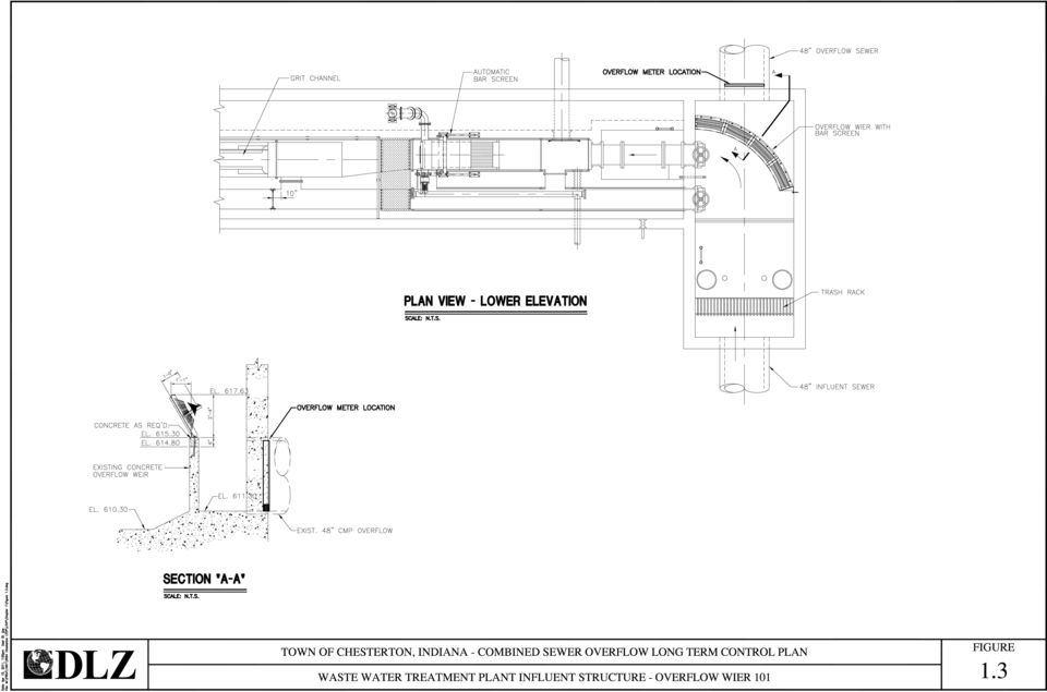
6 1.0 CHARACTERIZATION OF THE COMBINED SEWER SYSTEM 1.1 Sewer System Description The Town of Chesterton Utilities combined and sanitary sewer system covers the area shown in Figure 1.1. The Town of Chesterton Utility operates under NPDES Permit No. IN the Effective date is September 1, 2009 and the expiration date is August 13, The system includes one (1) permitted combined sewer overflow (CSO), identified as 101, which is located at the Wastewater Treatment Plant Combined Sewer Overflow 101 Overflow 101 is located in the Influent Structure at the WWTP. Figures 1.2 and 1.3 show the location and orientation of the overflow weir. The WWTP is connected to the collection system by a 48 influent sewer. Sewage is screened through a trash rack with 4 openings and is diverted into the WWTP by the overflow weir. A CSO event occurs when the sewage flow exceeds the WWTP peak flow capacity during wet weather. Once a CSO event begins the overflow is screened through bars with 1 openings to remove floatable and other solids larger then 1. The overflow is metered in the outfall sewer to document the overflow occurrence prior to being mixed with the WWTP effluent and being discharged to the East Branch of the Little Calumet River Areas Served by Combined Sewers Combined sewers in Chesterton were constructed, as in most combined sewer systems, until the 1960 s. Since that time sanitary and storm sewers have been constructed into new areas of the town as growth has occurred. The Town of Chesterton currently has an ordinance in place that prohibits the construction of new combined sewers. The areas that are currently served by combined sewers are isolated due to the Towns aggressive program to separate the combined sewers. Areas that still have combined sewers are shown in Figure 1.4 and include the following: Page 1-1 of 4

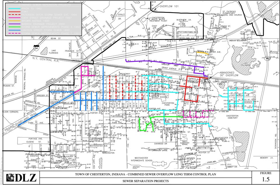
7 Area A - includes storm water inlets in the alleys between 13 th and 12 th streets and 12 th and 11 th streets between Broadway and West Indiana Avenue. Area B - includes the area bounded by Jefferson Street to the north, Calumet Street to the east, Fifth Street to the west and generally Richter Street to the south Areas Served by Sanitary Sewers Sanitary sewers have been constructed in Chesterton since the 1960 s. The current sewer use ordinance prohibits the connection of storm water inflow into sanitary sewers. In some areas residents have illegally connected their foundation drains to the sanitary sewers. This has been seen during flow monitoring of the sanitary sewers during wet weather. The Town now conducts inspections of new construction to prevent the connection of foundation drains to sanitary sewers. During the last twenty years the Town of Chesterton has been aggressive in the separation of the combined sewers in the older areas of the Town. These areas are shown in Figure 1.5 along with the approximate year each project was constructed. The separation was accomplished by the construction of new storm sewers and moving the storm inlets from the combined sewers to the storm sewers. The separation of the combined sewers in the areas shown in Figure 1.5 has reduced the inflow significantly and has enabled the town to eliminate an overflow at Calumet Road and Broadway that discharged to Coffee Creek. Though the separation projects removed the storm inlets in the streets from the combined sewers, they did not include the elimination of inflow and infiltration (I/I) from open joints, house laterals, roof down spouts or the disconnection of foundation drains. Because of this there are still wet weather peak flows in the separated sanitary sewer system Areas Served by Storm Sewers The Town of Chesterton has a number of outlets for storm drainage in the town. These include: Little Calumet River, to the north Page 1-2 of 4

8 Coffee Creek and Sand Creek, to the east. Pope O Conner Ditch, to the southeast. Swanson Lamport Ditch, to the south. Peterson Ditch, to the west. Gustafson Ditch to the southwest. Each of the drainage outlets are tributary to the East Branch of the Little Calumet River. As discussed in the Town has been aggressive in the separation of the combined sewers. Figure 1.5 includes the storm sewers that have been constructed in conjunction with the separation of the combined sewers. Most of the separation projects have been completed with the construction of storm sewers and the disconnection of inlets from the combined sewers and reconnection to the new storm sewer. As the town has grown since the 1960 s new areas of development have included storm drainage systems. These systems are now required as extension of the combined sewers or connection of storm water to the sanitary sewers have been prevented by the sewer use ordinance Town of Porter Besides the Town of Chesterton the Utility accepts and treats the sanitary sewage from the Town of Porter. The Porter sewer system is connected to the Town of Chesterton Utilities sewers just up stream of the WWTP on League Drive as shown in Figure 1.1. Chesterton Utilities has an agreement with the Town of Porter to treat up to 809,000 GPD. There is no limit to the peak flow in the agreement. The Porter sewage flows are affected by wet weather and contribute to the CSO s at Overflow Indiana Boundary Conservancy District Chesterton also accepts and treats the sanitary sewage from the Indiana Boundary Conservancy District. Chesterton Utilities has an agreement with the district to treat up to 81,000 GPD. The district does not have a problem with wet weather I/I to the extent that it causes sanitary sewer overflows. 1.2 Sewer System Mapping The sewer system maps that are currently in use are shown in Figure 1.1. The maps include both sanitary and combined sewers. The Town has not Page 1-3 of 4

9 included storm sewers on the overall sewer map to date but is working towards that goal. Storm sewer as-built plans are on file at the utility offices and the Town has hired a storm water engineer and formed a Storm Water Board to help manage the storm water systems within the Town. Rim and pipe invert data is available for most manholes and the Town is currently working to collect the data from all the manholes Page 1-4 of 4

10

11

12
13

14
15 2.0 CSO HISTORICAL DATA REVIEW In the summer of 2005 a metering program was initiated to collect data that could be utilized in the development of a hydrologic/hydraulic computer model. This section identifies the data collection strategy and the hydrologic/hydraulic computer model development. 2.1 Modeling Approach Part of the alternatives analysis that is presented in Section 5 includes the IDEM guidance for treating the 1-year 1-hour storm and the 10-year 1- hour storm as defined as follows: Provide for retention and treatment at the wastewater treatment plant, of combined sewage flows generated during storm events up to the 1-year, 1-hour storm Provide for primary treatment and disinfection of combined sewage flows generated during storm events larger than 1-year, 1- hour storm up to the 10-year, 1-hour storm Provide some primary treatment and disinfection of combined sewage flows generated during storm events above the 10-year, 1- hour storm Furthermore, IDEM has defined that the rainfall depths used in the analysis shall be as defined in Bulletin 71, Rainfall Frequency Atlas of the Midwest, and the rainfall shall be of uniform intensity and distribution over the entire service area for duration of exactly one hour. The 1-year 1-hour storm depth is 1.14 inches and the depth for the 10-year 1-hour storm is 1.98 inches as shown in Table Rain Fall Data Based on IDEM guidance the model will determine the flows generated by the 1-year 1-hour storm and the 10-year 1-hour storm. In past years, rainfall data was collected at the treatment plant with a rain gage. Data was collected from the rain gage daily and recorded as inches of rain. The rain data did not include intensity of the rainfall or the time the rain started or ended. To determine the wet weather flows based on storm intensities the Town developed a flow monitoring program and put it into place on August 22, 2005 with the installation of a temporary tipping bucket rain gage at the WWTP. The rain gage was left in place until November 5, In May 2006 the Town purchased a tipping bucket rain gage and permanently Page 2-1 of 5

16 installed it at the WWTP and connected it to the WWTP monitoring system. Data that is collected by the rain gage is automatically downloaded to the plant monitoring system and stored in the data memory. The WWTP rain gage is located generally in the center of the sewer systems, which includes both the Chesterton and Porter areas. The gage is in an open area and is not obstructed by tall buildings or trees. The site is secure and data is easily retrievable. 2.3 Wet Weather Flow Modeling As there is only one overflow within the Chesterton system located at the WWTP influent building, the computer model was developed to identify the flows at that point. To accomplish, this flow monitoring data was used from three monitoring points including Eighth and Carla Street (Meter 8), Franklin (Meter 4) and Marquardt (Meter 3). The wet weather flow modeling meters were located as shown on Figure Chesterton Flow Monitoring The Town owns six (6) portable flow meters and has been monitoring flow in the collection system since the spring of Figure 2.2 is a map of the collection system showing the location of the flow monitoring points that were used over the last four years and there tributary area. This information helped develop benchmark flows in various areas in the system to allow the town to check and monitor available capacity, particularly in areas of growth, changes in Infiltration and Inflow (I/I) over time and to verify the monthly flow data that is provided by the Town of Porter and Indian Boundary Conservancy District for billing purposes. The ongoing metering program will be included in the combined sewer overflow operational plan (CSOOP) for further reference. For modeling purposes the Eighth and Carla Street (Meter 8) was utilized to determine the flows to the WWTP and CSO Overflow 101. Meter 8 is positioned as shown on Figure 2.1 to monitor flows from a major portion of the Chesterton system. It also includes the Indian Boundary Conservancy District system and a number of collection areas of the Porter system Porter Flow Monitoring The Town of Porter (Porter) owns and operates their sanitary sewer collection system but utilizes the Town of Chesterton s Wastewater Treatment plant for treatment. To transport the Porter sanitary wastewater to the WWTP they utilize 7 connection points Page 2-2 of 5

17 to the Chesterton sewers. The Porter sewer system is shown in Figure 2.1. In 2007 Porter entered into an Agreed Order Case # W with IDEM to eliminate sanitary sewer overflows (SSO). As part of that consent decree Porter completed a flow monitoring program that resulted in a report entitled Sanitary Sewer Baseline Flow Analysis Summary dated April 30, A copy of the report is included in Appendix B. The flow analysis identified flows from each collection basin tributary to the Chesterton system for the 1 year 1 hour, 10 year 1 hour and the 50 year 18 hour storm events. Also the diurnal dry weather flows were identified and included in the report. Two of the 7 connection points were used in the determination of flows to CSO Overflow 101 including: Marquardt (Meter 4) The Meter 4 is positioned to monitor flows from the Porter sewer system in the area shown on Figure 2.1. Chesterton installed a meter in that same general area as shown, early in the flow monitoring period. However, an SSO in the Porter system was located in the collection system and the overflow amounts could not be determined. As part of the Porter consent decree, the Porter baseline report provided the flow data that was utilized in the computer model development. Porter maintains a meter in that area which is used for billing purposes. However, only totalized data is provided from the meter which is insufficient for modeling purposes Franklin (Meter 3) 2.4 Overflow 101 Monitoring The Meter 3 is positioned to monitor flows from the Porter sewer system in the area shown on Figure 2.1. The Franklin meter was also part of the Porter consent decree and flow from this collection area was part of the Porter baseline report providing flow data that was utilized in the computer model development. Overflow 101 is monitored using an area velocity meter in the outfall pipe to the river. The meter is located just downstream of the overflow weir in the 48 overflow pipe as shown in Figure Page 2-3 of 5

18 The current meter was installed in early 2003 and reads velocity in both directions. This is important as the flow in the outfall pipe is affected by the water level in the East Branch of the Little Calumet River. As the river rises river water will flow back up the outfall pipe and a velocity and depth is recorded by the meter. Data from the overflow meter is used to determine the volume of overflow during a CSO event for the MRO reporting. 2.5 WWTP Influent Monitoring WWTP Influent is monitored with a meter located on the lift station force main located in the influent structure. The meter is monitored by the WWTP SCADA system and provides flow readings every 60 seconds and also totalizes the flow. This meter provides the average daily and peak daily flows reported on the MRO s and CSODMR. 2.6 Wet Weather Flow Modeling As the Porter wet weather flows were modeled in the Base Line Study (Appendix B) those flows will be used and a model will not be developed as part of this report for Meter 3 and 4 areas. This section provides a summary of the hydrologic/hydraulic modeling procedure used to predict the 1-year, 1-hour storm event and the 10-year, 1-hour storm event stormwater flows to the Chesterton Wastewater Treatment Plant. In particular, this section summarizes the hydraulic/hydrologic modeling and calibration for the area tributary to Meter 8. Appendix C includes a Technical Memorandum describing the methodology that was used to determine the 1-year 1-hour and the 10-year 1-hour design storms for the Meter 8 area. The analysis utilized rainfall and flow meter data in conjunction with the PCSWMM hydraulic/hydrologic model for flow simulation. 2.7 Model Flow and Volume Predictions The storage volume required at the Chesterton wastewater treatment plant to store/treat the combined sewer inflow corresponding to the 1-yr 1-hr and the 10-yr 1-hr design storms are a combination of a number of flows. As discussed above, flows were modeled for meter areas 3, 4 and 8 feeding the WWTP as shown in Figure 2.1. The combination of these three flows, plus the diurnal flows, total the flows to the WWTP. If the total flow exceeds the 10 MGD peak capacity of the WWTP an overflow will occur unless storage is provided to contain the peak flow Page 2-4 of 5

19 2.7.1 Dry Weather Diurnal Flows Diurnal flows were determined from flow data collected by the WWTP influent meter. The diurnal flow was computed by averaging flows from dry periods between July 21-26, 2006, August 11 18, 2006 and October 28 November 5, The average dry weather flow totaled 2.29 MGD. The current WWTP design capacity is 4.6 MGD so the diurnal flows were increased by a factor of The diurnal curve for this period, with its average plotted on the curve, is shown in Figure 2.3. Increasing the diurnal flow to 4.6 MGD will allow growth in the community to the WWTP s current capacity without affecting the capacity of the wet weather treatment. 2.8 Predicted Wet Weather Flows to the WWTP To determine the wet weather flow the Chesterton meter area 8, Porter metering areas 3, 4 and the diurnal flows were added together. To provide a safety factor the peaks of each area flow including the diurnal flow were shifted so that the peak flows coincide resulting in the maximum expected hydrograph (storm and sanitary combined) that the wastewater treatment plant would see for the design storm event. To size wet weather treatment process the peak flow capacity of the WWTP of 10 MGD was subtracted from the total wet weather flow One Year One Hour Storm Table 2.2 and Figure 2.4 illustrates the wet weather flow hydrograph model for the 1year 1 hour storm. The peak flow to the WWTP is MGD and the wet weather volume over the 10 MGD peak capacity of the WWTP is 200,000 gallons Ten Year One Hour Storm Table 2.3 and Figure 2.5 illustrates the wet weather flow hydrograph model for the 10 year 1 hour storm. The peak flow to the WWTP is 26 MGD and the wet weather volume over the above the 10 MGD peak capacity of the WWTP is 761,000 gallons. M:\PROJ\1061\5964 Chesterton LTCP\LTCP\Chapter 2\Chapter 2-07.doc Page 2-5 of 5

20

21
22 3.0 CONSIDERATION OF SENSITIVE AREAS It is the responsibility of the NPDES permit holder to identify all sensitive areas. The NPDES permit holder must assess exactly what is occurring along the waterways which flow through their jurisdictions and to which their CSOs discharge. The elimination, relocation or control of combined sewer discharges to sensitive areas is given a high priority in the Federal and State CSO policies Identification of Sensitive Areas IDEM defines sensitive areas as waters impacted by CSO discharges, which must be given the highest priority for CSO discharge elimination, relocation or control. Examples of sensitive areas include: Threatened or Endangered Species Habitat The Indiana Department of Natural Resources, Division of Nature Preserves conducted an Indiana Natural Heritage Data Center database search for the Chesterton area on April 5, The database includes endangered, threatened, and rare species, high quality natural communities and significant natural areas. The database reflects reporting from specific field studies conducted by independent research groups. As threatened or endangered species are located, the findings are reported to the State and entered in the database specified by USGS Quadrangle Map township, range, and section numbers. The search indicated that the Rana pipiens, northern leopard frog, was documented from the Little Calumet River just northwest of Chesterton in Figure 3.1 illustrates the threatened, endangered, or rare species area Primary Contact Recreational Areas A water providing full body contact recreation means an area, both land and water, that is deemed important by local municipal, state, or federal governments for their recreational or educational value. Typically, local municipal, state, or federal governments actively support or provide maintenance to these areas. These areas, which relate to activities where small amounts of water are likely to be Page 3-1 of 5
23 ingested, can be locally designated for such public activities as swimming and water skiing. The Indiana Department of Natural Resources, Outdoor Recreation maintains the Indiana Recreation Facility Inventory. This inventory lists federal, state, county, municipal, and township-owned facilities with water bodies (lakes, ponds, or rivers) used for swimming, fishing, boating, or water skiing. On April 5, 2004 the Recreation Facility Inventory listed the following water body locations: Water Body Site Address City Reason Burns Ditch Little Calumet River Lake Michigan Izaac Walton League Miller Chapter Marquette Yacht Club Lefty s Coho Landing 1250 N. Crisman Road 1218 N. Crisman Road 6161 Burns Waterway Portage City Marina Hawthorn Park 500 Ackerman Drive Indiana Dunes 1110 N. National Mineral Lakeshore Springs Road Port of Indiana State Fishing Site Ogden Dunes Beach Access Port of Indiana Portage Portage Portage Portage Porter Porter Portage Ogden Dunes Access Access Paved Access, Boat Rental Paved Access Adjacent to waterbody Beach, Fishing, Swimming, Access Fishing along shore Beach, Fishing, Swimming Site Porter Beach Porter Beach, Fishing Figure 3.1 illustrates the primary contact recreational areas Page 3-2 of 5
24 Drinking Water Source Waters Surface drinking water intakes are considered a sensitive area for obvious human health factors. For purposes of completing the LTCP, a public surface water supply intake includes a point of intake used as a potable water source along surface waters downstream of the CSO discharge locations. The term is not intended to include ground water sources. An IDEM database containing 72 public water supply intakes was reviewed. The database indicated several public water supply intakes exist along Lake Michigan within approximately 25 stream miles of the Chesterton CSO. It is approximately 8.5 stream miles from the Chesterton CSO discharge on the East Arm of Little Calumet River down Burns Ditch and ultimately to Lake Michigan. A radius of 16.5 miles was explored along Lake Michigan from the entrance of Burns Ditch, which resulted in the identification of the following intakes that could potentially be influenced by the Chesterton CSO: Public Water Supply ID Indiana- American Water Co (Northwest Indiana Water Company) Indiana- American Water Co (Northwest Indiana Water Company) East Chicago Water Works Whiting Water Plant Hammond Water Works Department Michigan City Department of Water Works System Name City Intake Gary Lake Michigan Odgden Dunes Gary Lake Michigan Borman East Chicago Whiting Hammond Michigan City Lake Michigan Lake Michigan Lake Michigan Lake Michigan Figure 3.2 illustrates the locations of the cities that have public water supply intakes within approximately 25 miles of the Chesterton CSO Page 3-3 of 5
25 Outstanding State Resource Waters The Indiana Administrative Code at 327 IAC (b) did not list the Little Calumet River, Burns Ditch, or Lake Michigan as exceptional use waters. However, in reviewing the Indiana Administrative Code at 327 IAC 2-1-2(3) and 327 IAC (b) the Indiana portion of the open waters of Lake Michigan and all waters incorporated in the Indiana Dunes National Lakeshore were defined to be outstanding waters. Figure 3.1 illustrates the outstanding state resource waters Prioritize CSO Control Implementation The IDEM requires communities to evaluate the CSOs and assign a priority for addressing each one, based upon existing uses and particularly sensitive areas. The EPA's CSO Control Policy states, that for sensitive areas, the LTCP should: Prohibit new or significantly increased overflow volumes into the sensitive areas; Eliminate or relocate overflows that discharge to sensitive areas: Wherever physically possible and economically achievable, except where elimination or relocation would provide less environmental protection than additional treatment, or; Where elimination or relocation is not physically possible and economically achievable, or would provide less environmental protection than additional treatment, provide the level of treatment for remaining overflows deemed necessary to meet Water Quality Standards for full protection of existing and designated uses; Where elimination or relocation has been proven not to be physically possible and economically achievable, permitting authorities should require, for each subsequent permit term, a reassessment based on new or improved techniques to eliminate or relocate, or on changed circumstances that influence economical feasibility Page 3-4 of 5
26 The implication is simply that even if it is not physically possible and economically achievable to eliminate or relocate overflows from sensitive areas when the LTCP is first approved, it does not relieve the community of the responsibility to continue to evaluate and assess the situation over time. As technologies or economic circumstances change with time, it may become clear that the existing CSO can be eliminated or relocated. The intent of this element of the LTCP is to clearly demonstrate that consideration of sensitive areas has been accomplished through identifying the sensitive areas and determining the type of controls that are physically achievable. The evaluation of alternatives for the protection of the sensitive areas will be presented in Chapter Page 3-5 of 5
27
28
29 4.0 MAXIMIZING TREATMENT AT THE WWTP 4.1 Wastewater Treatment Plant Capacity The WWTP expansion was completed in September 2006, which increased the average daily flow from 2.7 MGD to 4.6 MGD. The peak flow capacity was expanded from 5.7 MGD to 10 MGD. 4.2 Hydraulic Stress Test To verify the peak flow capacity a hydraulic stress test was completed on March 23, The stress test was preformed with the UV bulbs in place. Two tests were completed. The first test limited the flow to 10 MGD and the second allowed the flow to reach 11 MGD. In both instances the plant was able to pass the flow hydraulically. Water samples were taken for E. coli. No violation of the NPDES summer time limits occurred during the tests. Because the test flow was only sustained for approximately 10 minutes the performance of the clarifiers could not be analyzed. Since the stress test was completed the WWTP has had a number of wet weather events and the operators were able to maximize the flow through the WWTP to 11 MGD. There are a number of factors that limit the flow through the WWTP as discussed below. 4.3 Flow Limiting Elements Currently the WWTP staff limits the flow to peaks to 10 MGD to prevent the final clarifiers from bulking sludge. If sludge begins to bulk the flow is further reduced to allow the clarifiers to recover. The following elements limit the peak flow and should be addressed as part of the LTCP alternatives Final Clarifier Flow Split It is difficult to maintain solids within the final clarifiers because of limited flow splitting abilities to prevent overloading a clarifier and causing sludge to bulk into the effluent Variable Speed Pumping The lack of full range variable speed pumping at the influent lift station pulses the flow thru the plant causing solids in some clarifiers to bulk Page 4-1 of 2
30 4.3.3 Headwork s Hydraulics Another area that limits the flow capacity includes the plant head works. Operator attention is required to prevent the flow from overtopping the grit channel floor, which could potentially flood the lift station dry well. To prevent this, a valve next to the overflow weir and before the bar screen is partially closed to limit the flow to the amount of flow that the pumps are putting out. Over operating the valve will limit the flow to the plant increasing the amount of overflow or continue to flood the headworks, which is time consuming for the operators Ultra Violet (UV) Light Disinfection Structure The other area that limits the flow is the UV disinfection structure in which the excessive high flows will float the light bulb units and cause the bulbs to break. Again procedures are being developed to maximize the flow and prevent flooding and UV bulb damage Page 4-2 of 2
31 5.0 CSO CONTROL ALTERNATIVES 5.1 Historical CSO Reduction The Town of Chesterton has been very proactive in the elimination of combined sewer overflow by the following actions: Source Control As discussed in Section the Town of Chesterton during the last twenty years has been aggressive in the separation of the combined sewers in the older areas of the Town. These areas are shown in Figure 1.5 along with the approximate year each project was constructed. The separation was accomplished by the construction of new storm sewers and moving the storm inlets from the combined sewers to the storm sewers. The separation of the combined sewers in the areas shown in Figure 1.5 has reduced the inflow significantly and has enabled the Town to eliminate an overflow at Calumet Road and Broadway that discharged to Coffee Creek. Because of this separation the average flows to the WWTP have reduced between 100,000 to 400,000 GPD while the town has continued to experience growth. Though the separation projects removed the storm inlets in the streets from the combined sewers they did not include the elimination of I/I from open joints, house laterals, roof down spouts or the disconnection of foundation drains. Because of this there are still wet weather (WW) peak flows in the separated sanitary sewer system Calumet Street Separation The Calumet Street Separation covers the area shown in Figure 5.1. The project is currently under construction and will be completed in Collection System Controls The Town has implemented a collection system control during the last WWTP expansion, which was completed in September The project included the raising of the overflow weir by 6 inches. This allowed the additional inline storage of WW flow by the 48 interceptor sewer and other connecting sewers depending on the hydraulic grade line of the WW flow. Also the plant expansion Page 5-1 of 10
32 increased the peak flow capacity of the WWTP from 5.7 MGD to 10 MGD. With the additional inline storage and increased plant capacity overflow amounts have been reduced. 5.2 Treatment Technologies The treatment technologies that the Town of Chesterton has implemented include the following: Overflow Weir 101 Bar Screen Under the WWTP expansion project a bar screen was added on top of the overflow weir. The bar screen has 1 inch spacing to screen out floatable materials and other solids 1 inch and larger. The screen is detailed in Figure WWTP Trash Rack The WWTP Trash Rack is located in the WWTP influent structure up stream of the overflow weir before flow is diverted into the bar screen and grit channel. The intent of the trash rack is to screen out any solids that are 4 inches and larger to protect the WWTP equipment. The trash rake also provides screening during an overflow event WWTP Expansion As discussed earlier in Section 4 the WWTP staff continues to maximize the treatment at the WWTP. The treatment plant peak capacity is key to the reduction of CSO occurrences CSO Metering As discussed in Section 2 Chesterton has embarked on an extensive metering program to identify bench marking of collection area and to develop a computer model to determine the 1 year 1 hour and 10 year one hour storm flows tributary to CSO LTCP Alternatives Approach The WW treatment approach that the Town of Chesterton is taking with regard to the reduction of overflows is based on IDEM guidance (Policy - Water 016) for treating the 1-year 1-hour storm (1 year storm) and the 10- year 1-hour storm (10 year storm) as defined as follows: Page 5-2 of 10
33 5.3.1 Provide for retention and treatment at the wastewater treatment plant, of combined sewage flows generated during storm events up to the 1-year storm Provide for primary treatment and disinfection of combined sewage flows generated during storm events larger than 1-year storm up to the 10-year storm Provide some primary treatment and disinfection of combined sewage flows generated during storm events above the 10-year storm Furthermore, IDEM has defined that the rainfall depths used in the analysis shall be as defined in Bulletin 71, Rainfall Frequency Atlas of the Midwest, and the rainfall shall be of uniform intensity and distribution over the entire service area for duration of exactly one hour. The 1-year 1-hour storm depth is 1.14 inches and the depth for the 10-year 1-hour storm is 1.98 inches as shown in Table 2.1. Based on the above IDEM guidance the computer model was developed as discussed in Chapter 2 and Appendix C. 5.4 Alternative Development Storage Tank Location Analysis The WWTP property is shown in Figure 5.2. The tank locations that were considered are discussed below: Tank Location 1 There is a lot of land available to the east of the outfall sewer that could allow for gravity filling of the tank however this area was not considered for the following reasons: The area is low and susceptible to flooding There is a high probability that the area is a wetland Dewatering and special foundation requirements would add additional costs Tank Location 2 During the development of the 2004 LTCP the location that was being considered was adjacent to the little league baseball diamond and, though still on WWTP property, would impact the baseball facility. Representatives of the Page 5-3 of 10
34 State Park league expressed concern during public hearings at the time Tank Location 3 The third location that was considered is the area west of the sludge thickening building. This area has advantages over the other areas for the following reasons: Less impact on neighbors The site is out of the way for future WWTP expansion An additional tank could be installed adjacent to the proposed tank if required by future regulations The tank could be converted into a primary clarifier in a future plant expansion if WW flow reduction rendered the tank ineffective WW Storage Basin Two alternatives were reviewed for the construction of the WW storage basin. One was for rectangular poured in place concrete construction and the second was circular pre-stressed concrete construction. In the review of both alternatives it was determined that the rectangular tank was the best alternative for the following reasons: The rectangular tank fit the site better with a smaller foot print. The location and foot print allows for future tank construction adjacent to the site. The tank cleaning system would be more efficient Full Treatment of the 1 Year Storm Based on the results of the modeling discussed in Chapter 2, the 1 year storm will produce a peak flow of 14.7 MGD and 200,000 Gal above the WWTP capacity. The 10 year storm will produce a peak flow of 26 MGD. To process the flow, the sizing of the components would be based on Figure Storage Tank To store the 1 year storm the tank would have to store 200,000 Gal Primary Treatment Page 5-4 of 10
35 To provide primary treatment for the 10 year storm the alternative would include screening and grit removal. Primary clarification would also be provided by allowing settling in the storage tank. Flows from storms above the 1 hour storm would continue to be pumped to the storage tank and once full the tank would become a primary settling tank and excess flow would overflow out of the tank. Once the WW flows pass, the tank would be drained for full treatment through the WWTP. The primary solids would be flushed out of the tank with the tank cleaning system for removal in the primary tanks Disinfection Because the flows above the 1 year storm would be discharged to the Little Calumet River after primary treatment, the flow would have to be disinfected prior to discharge. Three disinfection options were considered, as follows: Ultraviolet Light Disinfection (UV) During the last WWTP expansion the disinfection process was converted from gas chlorine to ultraviolet light disinfection to eliminate the potential hazards of gas chlorine and de-chlorination process. During the evaluation of utilizing UV on the WW overflow it was determined that because the water would only receive primary treatment UV may not provide the disinfection levels necessary to meet the NPDES permit water quality standards. Because of this, UV was eliminated from further consideration Liquid Chlorination Liquid chlorination would be a viable option to meet the NPDES disinfection limits however there are disadvantages: Requires de-chlorination The chemical has a limited shelf life and because the overflow would be infrequent the chemical could be ineffective and have to be disposed of and replaced before an overflow occurs. Startup would be required under the stressful operating conditions of a major storm to assure disinfection and de-chlorination is provided Page 5-5 of 10
36 Gas Chlorination Gas chlorination would also be a viable option to meet the NPDES disinfection limits however there are disadvantages as follows: Requires de-chlorination The WWTP eliminated gas chlorine in the last expansion so going back to a gas process was not recommended by the WWTP staff. Because the overflow would be infrequent, startup would be required under the stressful operating conditions of a major storm to assure disinfection and de-chlorination is provided. As the gas system would be utilized so infrequently, operating procedures could be difficult to remember by operators which could cause safety issues Full Treatment of the 10 Year Storm During the development of the 1 year storage basin it became clear that by treating the full 10 year flow the disinfection process could be eliminated. The WW pumping, screening and grit removal would still remain the same size and have the same capacity. Storage and treating the 10 year storm would also further reduce the amount of overflow and the number of occurrences. Because of these reasons the Full Treatment of the 10 year storm was developed. Based on the results of the modeling discussed in Chapter 2 the 1 year storm will produce a peak flow of 26 MGD and 1,200,000 Gal above the WWTP capacity. To process the flow the sizing of the components would be based on Figure Storage Tank To store the 10 year storm the tank would have to store 1.2 MG WW Headworks Structure The headworks structure includes the grit removal process, screening process and WW pump station. A layout of the headworks structure is shown in Figures Two alternatives for the headworks structure layout were considered. One is on the south side of the headworks diverting Page 5-6 of 10
37 flow before the existing trashrack. The other is on the north side of the headworks building. Both alternatives included basically the same layout. It was determined that the north side was a better fit because the existing screening and grit process would be close to the same elevation which would provide easier constructability. The south side of the existing headworks is constructed shallower which would cause problems constructing the deeper WW grit and screening structure next to the shallow grit and screening processing area. 5.5 Recommended Alternative Based on the analysis described in Paragraph 5.4 the recommended alternative includes a storage tank sized to store and treat the 10 year storm located on the west side of the WWTP site as shown in Figure WW Tank Location Of the three locations considered in Paragraph the area 3 was selected because of the advantages of placing the tank at that location WW Storage Tank A schematic of the proposed WW Storage Basin is shown in Figure 5.8 and 5.9. The basin would be constructed partially in the ground with the top extending 5 feet above the ground. The basin will be covered to contain odors and prevent snow, leaves and other debris from falling into the tank. As the Porter wet weather force main is in the vicinity of the basin it will be tapped, valved and connected to the basin as shown in Figure 5.8. This will allow the Porter WW flows to go directly into the basin without having to be repumped to the basin through the WW headworks, saving operating costs and WW headworks capacity. A control valve adjacent to the Porter Basin Weir will control whether or not flow is diverted into the tank. This will allow operator flexibility and avoid sending dry weather flow to the basin if that forcemain is used periodically for dry flows. Wet Weather flows will enter the basin on the southwest corner of the tank. This will allow the flushing system to fill first to assure an efficient flush. Once the flushing basins are full, flow will overtop the flushing well wall and fill the basin. Once the storm Page 5-7 of 10
38 has passed and WWTP capacity is available, the tanks will be allowed to drain back into the headworks for full treatment through the WWTP. Drain flows will be controlled through the WWTP SCADA system and the tank control valve that will restrict the flow back to the WWTP based on the available WWTP excess capacity. If a storm exceeds a 10 year storm and the tank is full the WW pump station will shut down and flow will be allowed to overflow to the Little Calumet River. Once the tank is empty the flushing system will be initiated and each individual flushing gate will be opened in sequence to wash solids out of the tank and back to the headworks Headworks The concept of the WW headworks is to allow the existing headworks process to work as intended until the WW flow exceeds the pump stations capacity of 10 MGD. At this point the flow will backup and overflow gates to the WW screens and flow will then flow through the screens, grit tank into the wet well and the WW pumps will pump the excess flow to the storage basin. Once the storage basin is full the WW pump station will shut down and any flow in excess of the 10 MGD flow to the WWTP will overflow to the Little Calumet River. Operation flexibility is included in the layout of the WW headworks. This flexability includes: The grit and screening will be sized to treat 26 MGD based on the model predictions of the 10 year storm. The screening process includes two new screens and with the existing screen the combined firm capacity is 26 MGD with one unit out if service. This will allow the operators to take the existing screen and grit system off line and still provide flow to the WWTP. A channel will be constructed through the WW wet well which will allow flow to the existing wet well for pumping to the primary clarifiers. If the flow exceeds the 10 MGD capacity flow will backup and overflow the channel in the WW wet well and the WW Pumps will automatically pump the flow to the WW storage basin There will be an interconnect between the WW forcemain to the storage basin and the WWTP forcemain. This will allow Page 5-8 of 10
39 the operators the option to use the WW pumps to pump flow to the WWTP if the existing pump station is offline. WW Pump Station: The capacity of the WW Pump Station is to pump 26 MGD to the WW Storage Basin and the WWTP for treatment. The controls will be setup to automatically pump flow in excess of the WWTP Pumps to the WW Storage Basin without interaction by the operators. Final configuration and sizing of the WW Pumps and forcemain will be determined in the preliminary design. The schematic layout or the WW Pump Station is shown in Figures Consideration of Sensitive Areas As discussed in Section 3 there are sensitive areas downstream of CSO 101. It would not be cost effective to move the outfall to another location to bypass or avoid the sensitive areas. By implementing the recommendations identified in this section the Town of Chesterton will significantly reduce the overflow volume and overflow events to cause minimal impact on the sensitive areas Probable Project Cost Estimate A detailed line item list of the components for the recommended project was developed. This list was developed based on similar projects that have been designed, bid and construction completed. Although the recommended project is far from being fully developed it will include many of the same components. In many cases, units were assigned to components based on the information known to date. However, in some cases allowances were assigned to cover the costs of the components. To each of the components a unit price was assigned. These unit prices were developed from recent project bids, Means Manuals, or equipment supplier s proposals. Costs were also adjusted to the Northwest Indiana construction environment using Engineering News Records cost analysis. Because the project is yet to be fully developed, a 20% contingency was added to cover unknowns such as special foundation requirements and dewatering. Table 5.1 includes a summary of the probable project cost. The detailed cost break down is included in Appendix D. 5.6 Cost/Performance Considerations Note: Cost/Performance Considerations will be added once the Accountant completes their analysis Page 5-9 of 10
40 5.7 Implementation Schedule for CSO Controls Note: Implementation Schedule for CSO Controls will be added once the Accountant completes their analysis. 5.8 CSO Operation Plan Revisions The CSO Operation Plan will be revised to include the recommendations of the LTCP after it is approved and once each project is complete Page 5-10 of 10
41
42
43
44
45
46
47
48
49
50 Headworks and Storage Tank Anticipated Project Costs for Chesterton, Indiana LTCP SUMMARY DIV EXISTING CONDITIONS $0.00 DIV CONCRETE $1,834, DIV MASONRY $97, DIV METALS $136, DIV THERMAL AND MOISTURE PROTECTION $67, DIV OPENINGS $63, DIV FINISHES $46, DIV SPECIALTIES $5, DIV PLUMBING $43, DIV HEATING, VENTILATING, AND AIR CONDITIONING $67, DIV INSTRUMENTATION & CONTROLS $143, DIV ELECTRICAL $541, DIV EARTHWORK $1,198, DIV EXTERIOR IMPROVEMENTS $236, DIV UTILITIES $516, DIV POLLUTION CONTROL EQUIPMENT $2,508, Subtotal All Divisions $7,507, Construction Contingency Add 20% $ 1,501, Total Construction (Year 2011): $ 9,009, Escalation to Construction Assume in 2015 (3 3%) Add 9% $ 810, Engineering Design 10% $ 900, Construction Inspection 8% $ 720, Total Project Cost (Year 2015) $ 11,441, Page 1 of 1
Source Water Protection Practices Bulletin Managing Sanitary Sewer Overflows and Combined Sewer Overflows to Prevent Contamination of Drinking Water
 United States Office of Water EPA 916-F-01-032 Environmental Protection (4606) July 2001 Agency Source Water Protection Practices Bulletin Managing Sanitary Sewer Overflows and Combined Sewer Overflows
COMBINED SEWER OVERFLOW LONG-TERM CONTROL PLAN Executive Summary
 CITY OF LAKEWOOD COMBINED SEWER OVERFLOW LONG-TERM CONTROL PLAN Executive Summary MAY 2006 storage conveyance treatment performance Prepared for: City of Lakewood, Ohio Prepared by: Metcalf & Eddy of Ohio,
COMBINED SEWER OVERFLOW OPERATIONAL AND MAINTENANCE PLAN SUMMARY
 COMBINED SEWER OVERFLOW OPERATIONAL AND MAINTENANCE PLAN SUMMARY Revised: April 2014 Village of Wilmette, Illinois NPDES CSO Permit No. ILM580012 Chapter 1 Introduction This Operational and Maintenance
DRAFT Public Outreach Document for What s an SSMP?
 DRAFT Public Outreach Document for What s an SSMP? This easy to read document is developed and provided to interested parties to assist in educating cities, agencies, their management, elected officials
Unauthorized Discharges and Sanitary Sewer Overflows
 TCEQ REGULATORY GUIDANCE Field Operations Support Division RG-395 Revised April 2011 Unauthorized Discharges and Sanitary Sewer Overflows What does this document cover? The Texas Commission on Environmental
After the Flush. Safe disposal of our wastewater is a valued and complex, not-for-profit municipal service.
 After the Flush Published: July 14, 2011 Sewage or wastewater is something we rarely think or talk about. The wastewater from our toilets, showers, washing machines and dishwashers quickly departs our
Kansas City s Overflow Control Program
 Kansas City s Overflow Control Program Kansas City Water Services Water Wastewater Stormwater 2 Water Services Department 1000 Positions 835 Employees 3 Utilities FY 13/14 Budget = $307 million Water Wastewater
Texas Commission on Environmental Quality Page 1 Chapter 217 - Design Criteria for Domestic Wastewater Systems
 Texas Commission on Environmental Quality Page 1 217.31. Applicability. SUBCHAPTER B: TREATMENT FACILITY DESIGN REQUIREMENTS 217.31-217.39 Effective August 28, 2008 This subchapter details the design values
Rouge River Watershed, MI Region 5. Community Case Study ROU-1. Number of CSO Outfalls. Combined Sewer Service Area. Wastewater Treatment Capacity
 Community Case Study Rouge River Watershed, MI Region 5 Number of CSO Outfalls 168 Combined Sewer Service Area 93 square miles Wastewater Treatment Capacity 1,700 mgd (primary) 930 mgd (secondary) Receiving
Components of a Basement Flooding Protection Plan: Sewer System Improvements. November 2000
 Components of a Basement Flooding Protection Plan: Sewer System Improvements November 2000 Components of a Basement Flooding Protection Plan: Sewer System Improvements November 2000 SEMCOG 2000 Prepared
SANITARY SEWER BACKUP. Causes & Prevention
 SANITARY SEWER BACKUP Causes & Prevention A. PURPOSE The purpose of this publication is twofold: 1. It provides homeowners with basic information on the causes of sanitary sewer backups. 2. It provides
City and County of San Francisco 2030 Sewer System Master Plan TASK 400 TECHNICAL MEMORANDUM NO. 405
 City and County of San Francisco 2030 Sewer System Master Plan TASK 400 TECHNICAL MEMORANDUM NO. 405 REGULATORY CONSIDERATIONS FOR WET WEATHER COLLECTION SYSTEM BACKUPS FINAL DRAFT August 2009 2700 YGNACIO
Land Disturbance, Erosion Control and Stormwater Management Checklist. Walworth County Land Conservation Department
 Land Disturbance, Erosion Control and Stormwater Management Checklist Walworth County Land Conservation Department The following checklist is designed to assist the applicant in complying with the Walworth
Scattergraph Principles and Practice Characterization of Sanitary Sewer and Combined Sewer Overflows
 Scattergraph Principles and Practice Characterization of Sanitary Sewer and Combined Sewer Overflows Kevin L. Enfinger, P.E. and Patrick L. Stevens, P.E. ADS Environmental Services 494 Research Drive Huntsville,
Executive Summary Consent Decree
 OVERFLOW ABATEMENT PROGRAM Executive Summary Consent Decree The sewer system in Nashville dates back to the late 1800s and originally consisted of a combined sewer system, later transitioning to separate
The Clean Water Project What Is The Stormwater Impact?
 The Clean Water Project What Is The Stormwater Impact? Presentation To: Seminar On Water Issues Bob Weimar, PE, BCEE Chief of Program Management The Metropolitan District Sewage Overflows Have Become More
High-Rate Retention Treatment Facility for CSO Control in Windsor Riverfront East
 High-Rate Retention Treatment Facility for CSO Control in Windsor Riverfront East Jian Li, Ph.D., P.Eng., PE Senior Environmental Engineer Stantec Consulting Ltd. Water & Wastewater Treatment BMP Forum
Basement Flood Risk Reduction City of Winnipeg. Charles Boulet
 Basement Flood Risk Reduction City of Winnipeg Charles Boulet Outline Background Winnipeg Floodway Rain Events Winnipeg Sewer System Basement Flooding Flood Reduction Measures ICLR - BFRR Strategy 2 Where
CITY OF HIGHLAND PARK, ILLINOIS Stormwater Management Fact Sheet
 CITY OF HIGHLAND PARK, ILLINOIS Stormwater Management Fact Sheet WHAT IS STORMWATER MANAGEMENT? Stormwater management is the method for channeling rainfall through pipes and sewers away from property to
Allegany County Combined Sewer Overflows - Long Term Control Plan
 Allegany County Combined Sewer Overflows - Long Term Control Plan On December 14, 2001 the Maryland Department of the Environment (MDE) filed a Consent Decree and Judgment (Consolidated Case No. 01-C-00-18342-L)
INTRODUCTION AND BACKGROUND
 Chapter 1 INTRODUCTION AND BACKGROUND 1.1 INTRODUCTION The City of Lincoln s Sewer System Management Program (SSMP) generally describes the City s sanitary sewer system operation and maintenance procedures,
NPDES Permit No. IL0021695. Notice No. JCH:12012302.bah. Public Notice Beginning Date: November 27, 2012. Public Notice Ending Date: December 27, 2012
 Notice No. JCH:12012302.bah Public Notice/Fact Sheet Issued By: Public Notice Beginning Date: November 27, 2012 Public Notice Ending Date: December 27, 2012 National Pollutant Discharge Elimination System
DRAFT Guidelines for Manually Diverting Outdoor Wastewater to the Sanitary Sewer
 Only RAIN down the Storm Drain... DRAFT Guidelines for Manually Diverting Outdoor Wastewater to the Sanitary Sewer This publication applies to you if: You generate wastewater outdoors, and The wastewater
Number 2014-20 September 2014 SEWER LIABILITY
 Number 2014-20 September 2014. SEWER LIABILITY Sewer Backups: Most of us take the use of our wastewater and sewer systems for granted, while municipalities must be vigilant to ensure that citizens of the
Repairs Made With Under Pressure Installations Can Offer Reduced Risks And Expenses
 Repairs Made With Under Pressure Installations Can Offer Reduced Risks And Expenses They also give the community a built-in re-entry system for future monitoring and repair. BY BRETT HANES According to
5. Environmental Analysis
 5.11 The potential for adverse impacts on utilities and service systems was evaluated based on information concerning current service levels and the ability of the service providers to accommodate the
BASEMENT FLOODING. Prevention Guide for. Homeowners
 BASEMENT FLOODING Prevention Guide for Homeowners 1 Did You Know? Floods are the most common hazards in Canada. Water damage is a common cause of loss for homeowner insurance. A heavy rainfall can result
ecmar SECTION INSTRUCTIONS: Sanitary Sewer Collection Systems
 ecmar SECTION INSTRUCTIONS: Sanitary Sewer Collection Systems Please see the DEFINITIONS of terms at the end of this section. If you have any questions about these definitions, do not understand a question,
Maine Department of Environmental Protection Program Guidance On Combined Sewer Overflow Facility Plans
 Maine Department of Environmental Protection Program Guidance On Combined Sewer Overflow Facility Plans OVERVIEW The objective of a Combined Sewer Overflow (CSO) Facility Plan is to abate CSO discharges
Sensitive and Priority Areas
 Chapter 3 Sensitive and Priority Areas 3.1 Introduction U.S. EPA and IDEM policy require communities to place a priority on addressing combined sewer overflow (CSO) discharges to sensitive areas. The IDEM
Technical Feasibility of a Wet Weather Flow Treatment Facility
 Wastewater Master Plan DWSD Project No. CS-1314 Technical Feasibility of a Wet Weather Flow Treatment Facility Technical Memorandum Original Date: August 9, 2001 Revision Date: September 2003 Author: Tetra
System Optimization: The First Step in CSO Control Alternatives Development
 System Optimization: The First Step in CSO Control Alternatives Development Don Walker NEWEA 215 Specialty Conference Series October 26, 215 Outline System Characterization ü Groundwork for system optimization
City of Mebane Wastewater Collection and Treatment Facility
 City of Mebane Wastewater Collection and Treatment Facility For the Fiscal Year July 1, 2014 - June 30, 2015 City of Mebane Wastewater Collection and Treatment Facility For the Fiscal Year July 1, 2014
CHAPTER 10-2. Section 1 Inventory of Existing Sanitary Sewer Collection and Treatment Facilities
 CHAPTER 10-2 SEWAGE COLLECTION AND TREATMENT FACILITIES Section 1 Inventory of Existing Sanitary Sewer Collection and Treatment Facilities 1.1 SANITARY SEWER COLLECTION SYSTEM The City of Washougal operates
Greater Los Angeles County Region
 Attachment 6 Greater Los Angeles County Region IRWM Implementation Grant Proposal Monitoring, Assessment, and Attachment 6 consists of the following items: Monitoring, Assessment, and. The purpose of this
What is a CSO / SSO? Sewer Overflows. Prevalence of CSOs in the US. Magnitude of Problem (Local)
") Sewer Overflows Combined Sewer Overflows (CSOs( CSOs) Older, large cities built combined networks to convey sewage and stormwater Stormwater overwhelmed sewage flow, but only for short periods To reduce
Sewer Overflows Combined Sewer Overflows (CSOs( CSOs) Older, large cities built combined networks to convey sewage and stormwater Stormwater overwhelmed sewage flow, but only for short periods To reduce
Review of Footing Drain Disconnection Projects
 Wastewater Master Plan DWSD Project No. CS-1314 Review of Footing Drain Disconnection Projects Technical Memorandum Original Date: August 8 2002 Revision Date: September 2003 Author: CDM Table of Contents
Cambridge Wastewater Treatment Facility
 Cambridge Wastewater Treatment Facility Emergency Situations If you have a water or sewer emergency that relates to the City s utility system call the Public Works office at 763-689-1800 on normal working
CONFIRMING WET WEATHER TREATMENT FACILITY HYDRAULIC DESIGN WITH PHYSICAL MODEL STUDY
 CONFIRMING WET WEATHER TREATMENT FACILITY HYDRAULIC DESIGN WITH PHYSICAL MODEL STUDY TONY YEE, PE JARED HUTCHINS, PE METROPOLITAN SEWER DISTRICT OF GREATER CINCINNATI BLACK & VEATCH WET WEATHER TREATMENT
Town of Elkton & Cecil Soil Conservation District Checklist for Joint Agency Review Stormwater Management / Erosion and Sediment Control
 Town of Elkton & Cecil Soil Conservation District Checklist for Joint Agency Review Stormwater Management / Erosion and Sediment Control Project Name: Tax Map Parcel: Acreage: Plat: ADC Map & Grid Engineering
Work Practice: Wastewater Collection System Maintenance Plan Potential Safety Hazards
 Potential Safety Hazards Required items Potential PPE None Additional References - Collection System Related Work Practices & Forms Jet Truck Cleaning Work Practice (Do not drive on peoples driveway) CDL
CHAPTER 3 STORM DRAINAGE SYSTEMS
 CHAPTER 3 STORM DRAINAGE SYSTEMS 3.7 Storm Drains 3.7.1 Introduction After the tentative locations of inlets, drain pipes, and outfalls with tail-waters have been determined and the inlets sized, the next
Town of Essex NE Lagoon. Service Area. Essex Plant. Service Area. Pumping Station No. 4. Wastewater Pumped To NE Lagoons (Treatment Plant No.
 Town of Essex Basement Flooding Study Town of Essex NE Lagoon Service Area Pumping Station No. 4 Essex Plant Service Area Wastewater Pumped To NE Lagoons (Treatment Plant No. 2) Essex Treatment Plant (Treatment
The City of Boulder 75 th Street Wastewater Treatment Facility
 The City of Boulder 75 th Street Wastewater Treatment Facility Wastewater Collection and Treatment The Foundation of Public Health Wastewater Collection Boulder s wastewater collection system, also known
Guidelines for Precast Concrete Grease Interceptors
 Guidelines for Precast Concrete Grease Interceptors Purpose Provide an overview of the basic design principals that govern why gravity grease interceptors work Provide a forum for discussion of common
Update on the Metro Nashville Consent Decree Program. Scott Potter Ron Taylor
 Update on the Metro Nashville Consent Decree Program Scott Potter Ron Taylor 1 Why We Are Here Planned actions to meet Clean Water Act The types of projects that will be constructed The impacts of these
SECTION 1 UTILITY OVERVIEW, INTRODUCTION, and PROJECT BACKGROUND
 SECTION 1 UTILITY OVERVIEW, INTRODUCTION, and PROJECT BACKGROUND Wastewater Utility Overview In the late 1950 s, the Village of Old Forge began to realize the impacts of dumping sewage in the Moose River.
4.3 Cisterns and Rain Barrels
 4.3 Cisterns and Rain Barrels Rain barrels, cisterns, and tanks are structures designed to intercept and store runoff from rooftops. Rain barrels are used on a small scale while cisterns and tanks may
Florida Department of Environmental Protection
 Florida Department of Environmental Protection Background Mobile vehicle and equipment washing involves washing at a location where vehicles are based (such as a trucking company, warehouse, bus station,
ENVIRONMENTAL ASSESSMENT (EA) VILLAGE OF EAU CLAIRE - BERRIEN COUNTY INFILTRATION/INFLOW REMOVAL PROJECT APRIL 2015
 VILLAGE OF EAU CLAIRE - BERRIEN COUNTY INFILTRATION/INFLOW REMOVAL PROJECT APRIL 2015") ENVIRONMENTAL ASSESSMENT (EA) VILLAGE OF EAU CLAIRE - BERRIEN COUNTY INFILTRATION/INFLOW REMOVAL PROJECT APRIL 2015 I. PROJECT IDENTIFICATION Applicant: Authorized Representative: Village of Eau Claire
ENVIRONMENTAL ASSESSMENT (EA) VILLAGE OF EAU CLAIRE - BERRIEN COUNTY INFILTRATION/INFLOW REMOVAL PROJECT APRIL 2015 I. PROJECT IDENTIFICATION Applicant: Authorized Representative: Village of Eau Claire
ELIMINATE STORM WATER FROM ENTERING SANITARY SEWER SYSTEMS
 (408) 761 5882 http://www.sewerlock.net ELIMINATE STORM WATER FROM ENTERING SANITARY SEWER SYSTEMS 1. `The United States and various State Environmental Protection Agency regulations require elimination
Purpose and Approach. Introduction
 City of Ann Arbor Sanitary Sewer Wet Weather Evaluation Project Best Practices Sub- Group of the Citizens Advisory Committee Examples of Wet Weather Improvements from Other Communities December 5, 2013
PART 6 - STANDARD DESIGN AND CALCULATION FORMS 6.1 SANITARY SEWER DATA SHEET
 PART 6 - STANDARD DESIGN AND CALCULATION FORMS 6.1 SANITARY SEWER DATA SHEET Name of Municipality or Sewer District Name of Project Original Township and Lot Number Name of Engineer of Firm Preparing Plans
City of Green Bay Department of Public Works Engineering Department
 City of Green Bay Department of Public Works Engineering Department The Difference Between Sanitary & Storm Sewers Contact Information: Department of Public Works City Hall 100 North Jefferson Street,
Fats, Oil and Grease. Best Management Practices Manual. Information, Pollution Prevention, and Compliance Information For Food Service Facilities
 Fats, Oil and Grease Best Management Practices Manual Information, Pollution Prevention, and Compliance Information For Food Service Facilities Pinellas County Utilities Water Quality Management Division
Indiana State Department of Health Construction Guidelines for Gravity and Flood-Dose Trench Onsite Systems
 Indiana State Department of Health Construction Guidelines for Gravity and Flood-Dose Trench Onsite Systems The septic tank-absorption field sewage treatment system is composed of two major elements; the
Town of New Castle Utility Department Introduction
 Town of New Castle Utility Department Introduction Town of New Castle Utility Department Mission Statement Our commitment is to ensure that our customers receive high quality water and wastewater treatment
Almonte Sanitary District Sewer System Management Plan Adopted by the ALMONTE Board of Directors on_08/28/06
 Almonte Sanitary District Sewer System Management Plan Adopted by the ALMONTE Board of Directors on_08/28/06 1. Goals The goal of this SSMP is to provide a plan and schedule to properly manage, operate,
OVER-HEAD SEWER ASSISTANCE GRANT
 OVER-HEAD SEWER ASSISTANCE GRANT The Village of North Aurora has a vested interest in the proper operation of the North Aurora sanitary system. Understanding that some residential users of the sanitary
ATTACHMENT 3: SPECIFICATION FOR SEWER CLEANING
 ATTACHMENT 3: SPECIFICATION FOR SEWER CLEANING 1.0 General 1.1 The work covered by this section consists of providing all labor, equipment, material and supplies, insurance, accessories, tools, transportation,
Type of Sewer Systems. Solomon Seyoum
 Type of Sewer Systems Solomon Seyoum 0 Learning objectives Upon completion of this lecture, the participants will be able to differentiate between types of sewer systems and discuss different aspects of
Terry Biederman, PE- Director of Public Works Greg Gucwa, PE- Principal Johnson and Anderson Engineering
 DON T JUST REHAB IT, RENEW IT! WATERFORD TOWNSHIP, MICHIGAN IMPROVEMENTS TO A 3.0 MGD SEWAGE PUMPING STATION Terry Biederman, PE- Director of Public Works Greg Gucwa, PE- Principal Johnson and Anderson
Description of the Water Conserv II Facility
 Description of the Water Conserv II Facility Introduction The Water Conserv II (WCII) Water Reclamation Facility provides service to a majority of the southwest section of Orlando. The WCII facility has
PERMITTEE/FACILITY NAME: City of Detroit Water and Sewerage Department / Detroit Wastewater Treatment Plant
 Permit No. MI0022802 FACT SHEET PERMITTEE/FACILITY NAME: City of Detroit / Detroit Wastewater Treatment Plant COUNTY: Wayne DESCRIPTION OF EXISTING WASTEWATER TREATMENT FACILITIES: The Detroit (DWSD) owns
DIVISION OF WATER QUALITY CONSTRUCTION GRANTS & LOANS SECTION FAST TRACK AUDIT CHECKLIST
 DIVISION OF WATER QUALITY CONSTRUCTION GRANTS & LOANS SECTION FAST TRACK AUDIT CHECKLIST CERTIFICATION 1. Did the engineer submit a certificate of completion utilizing the appropriate page of the issued
CHELTENHAM TOWNSHIP. SANITARY SEWER UPDATE Public Works Committee Meeting September 7, 2010 Curtis Hall
 CHELTENHAM TOWNSHIP SANITARY SEWER UPDATE Public Works Committee Meeting September 7, 2010 Curtis Hall 1 SANITARY SEWER UPDATE 1. Overview a. The Problem b. Pennsylvania Department of Environmental Protection
CHAPTER 2 HYDRAULICS OF SEWERS
 CHAPTER 2 HYDRAULICS OF SEWERS SANITARY SEWERS The hydraulic design procedure for sewers requires: 1. Determination of Sewer System Type 2. Determination of Design Flow 3. Selection of Pipe Size 4. Determination
Improper storage of fuel on construction sites will increase the risk of water pollution that may occur as a result of leaks or spills.
 WQ-10 Best Management Practice (BMP) Water Quality Protection Guideline Secondary Containment Design Standards Fuel Storage on Construction Sites According to the EPA, the majority of water pollution in
GUIDANCE DOCUMENT FOR SIZING AND INSTALLATION OF GREASE TRAPS AND INTERCEPTORS
 GUIDANCE DOCUMENT FOR SIZING AND INSTALLATION OF GREASE TRAPS AND INTERCEPTORS Fort Worth Water Department, Pretreatment Services Division, (817)871-8305 A. Introduction: Part I: Guidance for Grease Trap
City of East Lansing CSO Control Facility Evaluation Demonstrative Approach to Meet WQS
 City of East Lansing CSO Control Facility Evaluation Demonstrative Approach to Meet WQS Jeff Johnston, East Lansing WWTP Superintendent & Tom Maxwell, P.E., Hubbell, Roth & Clark, Inc. East Lansing CSO
SEPTIC SYSTEMS. 1. Building sewer connects the building plumbing to the septic tank.
 SEPTIC SYSTEMS Who Has A Septic System? Approximately 30 percent of Connecticut s population is served by on-site subsurface sewage disposal systems (a.k.a. septic systems). This means a large percentage
Extreme Wet Weather in Brookfield. How to Keep Your Basement Dry During Heavy Rains and Floods
 Extreme Wet Weather in Brookfield How to Keep Your Basement Dry During Heavy Rains and Floods Relating Stormwater Drainage to Sewer Backups Brookfield has two separate sewer systems Storm sewer system
HYDROVEX. CSO, SSO and Stormwater Management Specialist Products and Services for North America
 HYDROVEX CSO, SSO and Stormwater Management Specialist Products and Services for North America A long tradition in excellence John Meunier Inc. has been serving North American municipalities and industries
Standard Operating Procedures for Flood Preparation and Response
 Standard Operating Procedures for Flood Preparation and Response General Discussion Hurricanes, tropical storms and intense thunderstorms support a conclusion that more severe flooding conditions than
CHAPTER 11 STORM DRAINAGE
 CHAPTER STORM DRAINAGE SECTION PC 0 GENERAL 0. Scope. The provisions of this chapter shall govern the materials, design, construction and installation of storm drainage. Storm water discharge shall be
FLORIDA ATLANTIC UNIVERSITY
 9 Supporting Data The purpose of the Element is to ensure the provision of public facilities and services required to meet the future needs of the University, including: Stormwater management, to protect
ORDINANCE NO. 511 ORDINANCE ESTABLISHING A COST REIMBURSEMENT PROGRAM FOR THE INSTALLATION OF OVERHEAD SEWERS OR BACKFLOW PREVENTION DEVICES
 ORDINANCE NO. 511 ORDINANCE ESTABLISHING A COST REIMBURSEMENT PROGRAM FOR THE INSTALLATION OF OVERHEAD SEWERS OR BACKFLOW PREVENTION DEVICES WHEREAS, Wheaton Sanitary District had a cost reimbursement
Grease Trap Maintenance, Procedures and Cleaning Logs
 SAWS Grease Reduction Program Grease Trap Maintenance, Procedures and Cleaning Logs Don t Feed the Grease Monster Best Management Practices for Commercial Food and Restaurant Facilities Train kitchen staff
Asset Management Answering the 5 Core Questions
 Asset Management Answering the 5 Core Questions by Timothy Taber, PE Barton & Loguidice Page 1 Drivers Asset Management Case Study 1. What is the current state of my assets? 2. What is my required sustainable
DESCRIPTION OF STORMWATER STRUCTURAL CONTROLS IN MS4 PERMITS
 DESCRIPTION OF STORMWATER STRUCTURAL CONTROLS IN MS4 PERMITS Phase I MS4 permits require continuous updating of the stormwater system inventory owned and operated by the MS4. They also include inspection
CITY OF NORTH RIDGEVILLE 7307 AVON BELDEN ROAD NORTH RIDGEVILLE, OH 44039 (440) 353-0819 WWW.NRIDGEVILLE.ORG
 353-0819 WWW.NRIDGEVILLE.ORG") CITY OF NORTH RIDGEVILLE 7307 AVON BELDEN ROAD NORTH RIDGEVILLE, OH 44039 (440) 353-0819 WWW.NRIDGEVILLE.ORG WHY IS THERE WATER IN MY BASEMENT? There are two major sources of water in a basement as the
CITY OF NORTH RIDGEVILLE 7307 AVON BELDEN ROAD NORTH RIDGEVILLE, OH 44039 (440) 353-0819 WWW.NRIDGEVILLE.ORG WHY IS THERE WATER IN MY BASEMENT? There are two major sources of water in a basement as the
The Town of Lakeshore Basement Flooding Information to Residents
 The Town of Lakeshore Basement Flooding Information to Residents The following information is intended for residents that have homes connected to Municipal storm and sanitary sewers. However, rural residents
1. Water Line Maintenance 2. Sanitary Sewer Maintenance 3. Spill/Leak/Overflow Control, Response, and Containment
 WATER AND SEWER UTILITY OPERATION AND MAINTENANCE Although sewage systems the operation and maintenance of public utilities are not considered themselves are not a chronic sources of stormwater pollution,
Performance Audit: Combined Sewer Overflow Consent Decree Impact
 Performance Audit: Combined Sewer Overflow Consent Decree Impact January 2014 City Auditor s Office City of Atlanta File #13.06 CITY OF ATLANTA City Auditor s Office Leslie Ward, City Auditor 404.330.6452
CLACKAMAS COUNTY ZONING AND DEVELOPMENT ORDINANCE
 1008 STORM DRAINAGE (3/24/05) 1008.01 PURPOSE To minimize the amount of stormwater runoff resulting from development utilizing nonstructural controls where possible, maintain and improve water quality,
Ann Arbor Wastewater Treatment Plant Facilities Renovations Project September 2015
 Ann Arbor Wastewater Treatment Plant Facilities Renovations Project September 2015 The Facilities Master Plan was completed in 2004 and identified the need for improvements to the City of Ann Arbor s Wastewater
DEPARTMENT OF ENVIRONMENTAL QUALITY
 PROJECT IDENTIFICATION DEPARTMENT OF ENVIRONMENTAL QUALITY City of Burton Sanitary Sewer Collection System Improvements State Revolving Fund (SRF) Environmental Assessment April 2015 Applicant: Authorized
Cost Estimating Procedures for Raw Sewage Overflow Control Program
 Raw Sewage Overflow Control Program April 23, 2004 Raw Sewage Overflow Control Program City of Indianapolis Department of Public Works Table of Contents Section Page 1.0 Introduction... 1 2.0 General Project
SECTION 812 SEWER LINE, MANHOLE AND WET WELL CLEANING
 812-1 SCOPE OF WORK: SECTION 812 SEWER LINE, MANHOLE AND WET WELL CLEANING a. The Contractor shall provide all labor, materials, equipment, and incidentals necessary to perform the cleaning of sewer lines,
VILLAGE OF GRANVILLE SEWER BACK-UP and WATER LEAK POLICIES
 VILLAGE OF GRANVILLE SEWER BACK-UP and WATER LEAK POLICIES SEWER BACK-UP POLICY General Sewer back-ups are an unfortunate, but common problem in older communities. A sewer back-up can create a health or
CHAPTER 11 STORM DRAINAGE
 CHAPTER 11 STORM DRAINAGE SECTION 11 GENERAL 11.1 Scope. The provisions of this chapter shall govern the materials, design, construction and installation of storm drainage. 11.2 Where required. All roofs,
Detention Ponds. Detention Ponds. Detention Ponds. Detention Ponds. Detention Ponds. Detention Ponds. CIVL 1112 Detention Ponds - Part 1 1/12
 CIVL 1112 - Part 1 1/12 The water cycle, also known as the hydrologic cycle, describes the continuous movement of water on, above and below the surface of the Earth. The water cycle, also known as the
STORMWATER POLLUTION PREVENTION PLAN TEMPLATE. 1.0 SITE DESCRIPTION 1.1 Project Name and Location Date
 STORMWATER POLLUTION PREVENTION PLAN TEMPLATE Disclaimer: This template was developed for guidance purposes only in an effort to assist Construction Storm Water permit applicants in meeting state and local
M E M O R A N D U M. Among the standard conditions contained in the NPDES permit is also a Duty to
 M E M O R A N D U M DATE: August 7, 2015 TO: FROM: SUBJECT: Metropolitan Wastewater Management Commission (MWMC) Matt Stouder, MWMC General Manager Capacity Management, Operations, and Maintenance (CMOM)
Sanitary Sewer Master Plan
 , Illinois Sanitary Sewer Master Plan EXECUTIVE SUMMARY Prepared by September 9, 2010 1670 South Taylorville Road Decatur, Illinois 62521 www.bgmengineering.com Sanitary Sewer Master Plan A. SCOPE OF STUDY
DID YOU KNOW... THE IMPACT OF ON-SITE SEWAGE SYSTEMS AND ILLICIT DISCHARGES ON THE ROUGE RIVER
 DID YOU KNOW... THE IMPAT OF ON-SITE SEWAGE SYSTEMS AND ILLIIT DISHARGES ON THE ROUGE RIVER by Barry Johnson, P.E., M.S., amp Dresser & McKee and Dean Tuomari, Wayne ounty Department of Environment The
MARYLAND AVENUE BACKUPS DURING AUGUST 31, 2014 STORM EVENT COMMUNITY OUTREACH
 MARYLAND AVENUE BACKUPS DURING AUGUST 31, 2014 STORM EVENT COMMUNITY OUTREACH MARYLAND AVENUE BACKUPS COMMUNITY OUTREACH MEETING AGENDA Introductions History of PWSA Actions August 31 Storm Impacts Short
City of Bakersfield Public Works Department Sewer System Management Plan December 2014
 City of Bakersfield Public Works Department Sewer System Management Plan December 2014 C:\Users\hmayberry\Desktop\SEWER SYSTEM MANAGEMENT PLAN 2014.doc 1 Sewer System Management Plan Index: Section 1 Goals
Outlet stabilization structure
 Overview of Sedimentation and Erosion Control Practices Practice no. 6.41 Outlet stabilization structure Erosion at the outlet of channels, culverts, and other structures is common, and can cause structural
Best Management Practices
 for The City of Paso Robles is required to implement a Phase II Municipal Water Program in order to reduce or eliminate the pollutants that enter our waterways from both storm water and non-storm water