CHAPTER Section 1 Inventory of Existing Sanitary Sewer Collection and Treatment Facilities
|
|
|
- Mariah Gibbs
- 8 years ago
- Views:
Transcription
1 CHAPTER 10-2 SEWAGE COLLECTION AND TREATMENT FACILITIES Section 1 Inventory of Existing Sanitary Sewer Collection and Treatment Facilities 1.1 SANITARY SEWER COLLECTION SYSTEM The City of Washougal operates and maintains approximately 35 miles of sanitary sewer collection lines and mains. The majority of the collection system consists of 6 and 8-inch diameter pipe with mains constructed of larger diameter pipe, ranging from 8 to 30-inches. 1.2 PUMPING FACILITIES AND FORCE MAINS Pump Station No. Location Pumps Table SEWAGE PUMP STATION DATA SUMMARY Force Main Size Approximate Capacity 1 14th and A Street Two 10 Hp, Smith & Loveless 500 gpm 8-inch 2 6th and K Street Two 10 Hp, Smith & Loveless 175 gpm 6-inch 3 S. 32nd Street Two 15 Hp, Cornell 600 gpm 4-inch 4 24th and L Street Two 47 Hp, Queen Pump Co gpm 6-inch 5 1 st Street at Marina Two 2 Hp, Flygt 250 gpm 4-inch 6 S. 37th Street Two 7.5 Hp, Flygt 340 gpm 6-inch 7 Dr. Eldridge Dr. Two 10 HP, Flygt 100 gpm 4-inch 8 Shepherd Road Two 10 HP, Flygt 890 gpm 8-inch 9 34 th and L Street Two 1.9 HP, Flygt 81 gpm 1.5-inch 10 Lookout North Two 10 HP, Flygt 275 gpm 3-inch 11 Sunset Ridge Two 3 HP, Flygt 50 gpm 4-inch 1.3 WASTEWATER TREATMENT PLANT DESCRIPTION The City s current system relies upon an activated sludge treatment plant that discharges to the Columbia River. The various components of that treatment plant are described in the following paragraphs. City of Washougal Sewer System Capital Facility Plan

2 Administration Building There is one administration building with a total floor space of about 700 square feet located in the northeast corner of the facility. This building contains separate rooms for restroom, laboratory, control, and disinfection. The building was originally constructed in the 1950's, with additions in the 1970's and 1990's. A recently completed draft General Sewer Plan (GSP) identified the existing administration building as deficient in both space and quality of construction. It recommended the construction of a new administration building as soon as funds became available. Major deficiencies include: 1) a laboratory room that is too small, 2) insufficient office space, 3) lack of operator locker rooms, 4) insufficient restrooms, and 5) insufficient operator lounge area. The City recently obtained funding for the design of a new administration building, with design scheduled for completion in Headworks Influent wastewater is conveyed by gravity sewers to the facility headworks where it passes through a manually cleaned trash rack and a mechanically cleaned spiral screen. The mechanical screen is located in an old screw pump structure as a cost savings measure, which presents undue operational difficulties. Currently, there are no grit removal facilities. The 1997 Engineering Report identified the headworks as deficient and recommended a new headworks facility. Design of a new headworks facility is currently underway. Secondary Treatment Biological treatment is provided by an oxidation ditch activated sludge process. The system includes an oxidation ditch, clarifier, return activated sludge (RAS) pumps, and waste activated sludge (WAS) pump. Raw wastewater from the influent pump station enters the 1,800,000 gallon oxidation ditch, which consists of an oval-shaped channel equipped with mechanical aeration and mixing devices. The effluent from the oxidation ditch flows to a clarifier distribution structure and then to two 84-foot diameter clarifiers where solids are settled. Disinfection Effluent from the plant passes through ultraviolet radiation (UV) disinfection before discharge. UV radiation has proven to be an effective bactericide and virucide for wastewater, while not contributing to the formation of toxic byproducts. Solids Treatment Treatment of waste solids is accomplished by long-term storage in three of the four lagoon cells (Cells #2, #3, and #4). In the lagoon, sludge undergoes facultative biological treatment. Both aerobic and anaerobic processes are present, which work to make the sludge suitable for land City of Washougal Sewer System Capital Facility Plan

3 application by reducing volatile solids and pathogens. Compared to alternative types of sludge treatment and disposal systems available, the existing facilities require a relatively high amount of manpower. The draft GSP addresses the fact that the sludge lagoons had limited capacity and would require supplemental stabilization facilities in the near future. The lagoons are currently treating biosolids adequately, but have created serious odor problems over several months of the year. Cell #1, which was historically used as an emergency overflow basin to compensate for lack of secondary clarifier redundancy, is planned for modification in the near future. Part of that cell will be utilized for construction of additional mechanical treatment facilities. Part of it will be converted to supplemental sludge storage area for temporary use until such time as mechanical solids treatment facilities are constructed (currently scheduled for 2008). Sludge Disposal The City has initiated a sludge management program that includes testing and land application of biosolids to leased property at the Port of Camas/Washougal. That disposal property is located about ¼ mile south of the sludge lagoons. A disposal permit has been acquired from the Southwest Washington Health District and Region 10 of the U.S. EPA. The first land application was accomplished in October of In 2005, a study was completed to identify additional land disposal sites. Efforts are currently underway to procure agreements with landowners and permit additional land applications sites. 1.4 INFILTRATION AND INFLOW (I&I) Infiltration is defined as subsurface water which enters the wastewater collection system through cracks, joints, or other deficiencies in the collection system. It is directly influenced by the local groundwater table and the structural integrity of the collection system. All collection systems experience some degree of infiltration. Each system must plan and allow for additional capacity to accommodate this flow contribution. Inflow is the component of I&I that is attributed to surface water, mainly stormwater runoff, entering the system through roof drains, storm drains, manhole covers, and other direct conduits to the sewer system. Inflow is directly influenced by storm events and usually occurs over a short period, during and after a storm event. Inflow is usually preventable by eliminating nonsewerage connections to the system. With older systems, however, identifying illegal sewer connections can be difficult. The majority of the wastewater collection system was constructed in Because it was mostly constructed with concrete sewer pipe, it is prone to infiltration. In recent years, the City has adopted high quality standards for new sewer main construction and has been diligent in their inspection services. City of Washougal Sewer System Capital Facility Plan

4 The City undertook significant corrective measures to identify and reduce the infiltration and inflow sources in Several significant sources of I&I were identified and eliminated. Based on EPA Standards, the City currently does not have excessive infiltration and inflow due to these corrective measures. Section 2 Forecast of Future Sanitary Sewer System Needs 2.1 LEVEL OF SERVICE STANDARDS FLOW PROJECTIONS Residential population projections were made using the most current information available and from the Comprehensive Plan. Historically residential population growth has varied between 0.5% and 6%, with an average over the last 30 years of approximately 2%. Wastewater flows are contributed by both residential land uses, and non-residential land uses, which include industrial and commercial uses. For purposes of sewer planning, flow and wasteload projections are based upon equivalent residential units (ERUs). An ERU represents the equivalent flow and wasteload from a single family. ERU values were calculated based upon the following assumptions: 1. Average household size is to be 2.59 persons per unit (1 ERU = 2.59 people). 2. Commercial, industrial, large industrial, and public equivalent ERU values were taken from the comprehensive plan. Using these assumptions, the following table represents projected growth within the UGA: City of Washougal Sewer System Capital Facility Plan

5 New Res. ERUs Table Population and ERU Projections ERUs Res. ERU Comm/ Large Year Actual Population Total Comm Industrial Public Ind. Total ERUs Population Equivalent ,800 3, ,556 6,300 16, , , ,572 6,804 17, , , ,587 7,352 19, ,414 1,395 5, ,603 7,842 20, ,338 1,752 5, ,619 8,251 21, ,155 2,068 5, , ,635 8,618 22, ,842 2,333 6, , ,652 8,936 23, ,377 2,539 6, , ,668 9,198 23, ,927 2,752 6, , ,685 9,468 24, ,496 2,971 6, , ,702 9,746 25, ,081 3,197 6, , ,719 10,030 25, ,683 3,430 7, , ,736 10,323 26, ,303 3,669 7, , ,753 10,624 27, ,942 3,916 7, , ,771 10,935 28, ,600 4,170 7, , ,789 11,255 29, ,278 4,432 8, , ,806 11,582 29, ,976 4,701 8, , ,825 11,921 30, ,695 4,979 8, , ,843 12,267 31, ,463 5,275 8, , ,861 12,636 32, ,200 5,560 9, , ,880 12,995 33,657 Avg. Annual Growth Rate 4% % 3% 3% 1% -- The Residential ERU Total was computed by adding the new residential ERUs for each future year to the 2005 ERU value. FLOW AND WASTELOAD PROJECTIONS Future per capita waste contributions were estimated based on existing per capita waste contribution and Department of Ecology (DOE) guidelines. The following table contains the per capita average contribution from , the DOE recommended design values for new wastewater treatment facilities, and the value used for future population loading. DOE guidelines use direct population, which assumes a higher per capita flow contribution. The per capita values in Table are based upon population equivalents as opposed to direct populations, using lower flow contribution values. City of Washougal Sewer System Capital Facility Plan

6 Table Per Capita Wastewater Loadings Future (2025) Present DOE Guideline Flow (gpcd) Dry Average 70 n/a 80 Wet Average 85 n/a 90 Max Month TSS/BOD 5 (lb/day) Average Annual To develop projected wastewater loadings, population projections contained in Table and future loading rates in Table were used. Future loading values presented in Table were developed by calculating a direct projection of population equivalent times the future unit values from Table Table Projected Wastewater Loadings Year: Population Equivalent: a 17,622 25,978 33,657 Flow (mgd) Dry Average Wet Average Maximum Month Peak Hour b TSS/BOD 5 (lb/day) 2,467 3,637 4,712 Notes a. Population equivalents include large industry. b. Peak Hour Flow - The peaking factor is 3.5 times the Dry Weather Flow. The peak hourly flows projected above were not based on the historical influent peaks. The WWTP has experienced extremely high peak flows measured at the influent plant over the last few years due to industrial discharges. The City is currently investigating the source or sources of these peak flows, and will be taking measures to reduce them. Section 3 Locations and Capacities of Future Facilities 3.1 SEWER PLANNING By state law, sanitary sewer system improvements need to conform to a State-approved General Sewer Plan which is formally adopted by City Council. A draft General Sewer Plan was recently completed. 3.2 COLLECTION SYSTEM GROWTH-RELATED IMPROVEMENTS City of Washougal Sewer System Capital Facility Plan
 Dry Average 1.41 2.08 2.69 Wet Average 1.59 2.34 3.03 Maximum Month 1.76 2.")
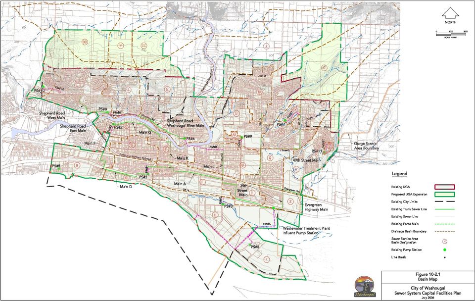
7 The sanitary sewer system is in relatively good condition, but some of the sewer mains and pump stations do not have adequate capacity to accommodate growth. Several of the system components are only slightly overloaded at future flows and thus will not require up-sizing if the existing infiltration and inflow can be removed. From that perspective, a certain amount of infiltration and inflow removal is deemed growth related. The following paragraphs summarize proposed improvements. Figure presents the basin map and Figure presents the proposed collection system improvements, and both are described in the following paragraphs by the subarea in which they are located. MAINTENANCE RELATED UPGRADES Maintenance related improvements are those that are required with or without growth. They include the following six items: 1. Pump Station Flow Meters 2. Pump Station #7 Abandonment 3. Pump Station #9 Abandonment 4. Pump Station #10 Abandonment 5. Pump Station # 11 Abandonment 6. U Street Bypass Sewer NORTHWEST SUBAREA CAPACITY UPGRADES The UGA northwest of the City is an isolated service area, separated from the rest of the UGA by the Washougal River. Wastewater from this area must be pumped across the river in order to be conveyed to the treatment facility. Recommended improvements to this portion of the UGA are: 1. Pump Station #13. This pump station would serve an isolated basin serving a 20-year estimate of 250 ERUs. The pump station would be a duplex pump station meeting minimum standards. Each pump would be sized at 150 gpm. It is considered a temporary pump station until such time as the City expands its city limits to the north. 2. Force Main #13. This force main would be a new 3,100-foot, 4-inch force main. It would discharge into the gravity sewer system on the south side of Woodburn Hill. 3. Pump Station #14. This pump station would be a duplex pump station meeting minimum standards. Each pump would be sized at 100 gpm (minimum capacity). It is considered a temporary pump station until such time as the City expands its city limits to the north. 4. Force Main #14. This force main would be a new 4,600-foot, 6-inch force main. It would discharge into the proposed Washougal River North Trunk (T26). City of Washougal Sewer System Capital Facility Plan

8 5. Pump Station #15. This pump station would be a duplex pump station meeting minimum standards. Each pump would be sized at 300 gpm. It is considered a temporary pump station until such time as the City expands its city limits to the north. 6. Force Main #15. This force main would be a new 1,600-foot, 6-inch force main. It would discharge into the proposed Washougal River North Trunk (T26). 7. Trunk Sewer T26. This 4,300-foot, 21-inch gravity line would serve basins W and CC, and the northeastern portion of basin N. This sewer will discharge to the upper end of the Washougal River North Interceptor (I8). 8. Interceptor I8 (Washougal River North Interceptor). This interceptor will extend 4,000 feet from PS#4 through existing streets and will terminate where the UGA boundary crosses Washougal River Road. This interceptor will be sized at 36-inch diameter to accommodate basins K, L, J, N, BB, W, and CC at build-out and two-thirds of X plus most of the 50-year service area that lies outside of the proposed UGA. This sizing assumes that it will receive flows from two thirds of Basin X by a sewer extension west across the Washougal River. 9. Trunk Sewer T24. This proposed trunk sewer, previously referred to as the Browns Lane sewer is to provide capacity relief to the lower section of Interceptor I5 (Shepard Road Washougal River Interceptor). This sewer will be sized to serve basins K, L, J, BB, and most of N at buildout. Trunk Sewer T24 will be a 1,500-foot, 21-inch gravity line. 10. Pump Station #8 Capacity Upgrade. The proposed Pump Station #8 upgrade will involve replacing the two existing pumps with higher capacity pumps. Each new pump will be sized at 550 gpm capacity. The emergency generator installed with the existing station will require replacement. Also, variable speed motors are proposed to help mitigate downstream surges, and to enable continued use of the wetwell, which is undersized if constant speed pumps are utilized. 11. Force Main #8 Extension. To alleviate a capacity problem in the sewer receiving flow from the existing force main, an extension is proposed to connect to a proposed downstream sewer (T24). This extension would involve the construction of a 1,900-foot, 8-inch force main along Shepard Road. 12. Pump Station #4 Capacity Upgrade. The proposed Pump Station #4 upgrade will involve replacing the two existing pumps with higher capacity pumps, providing a total of 1,100 gpm capacity. 13. Pump Station #4 Force Main. A new 6200-foot, 12-inch force main (Force Main #4-2) will be routed north up 24 th Street then east on M Street, crossing the Washougal River on a pedestrian bridge and continuing east along L Street, then south on 34 th Street and east on J Street to the intersection of J Street and 39 th Street. The proposed force main will be sized at 12-inch for 20-year flows from Basins BB, CC, W, K, L, J, and N. It is City of Washougal Sewer System Capital Facility Plan
. 8. Interceptor I8 (Washougal River North Interceptor).")
9 recommended that the existing 6-inch Force Main #4 (designated as FM #4-1) remain active and be utilized as emergency backup. NORTHEAST SUBAREA The northeast subarea of the UGA is largely developed. Most of the area that is not can be served by extending existing sewers uphill. Recommended improvements to this portion of the UGA are: 14. Stiles Road Interceptor (I9) This interceptor will extend 5,000 feet from Pump Station #9 (to be abandoned) north to the northern termination of the UGA at 20 th Street. It will be sized at 8-inch to accommodate one third of the flow from Basin X. The remainder of the flow from Basin X is assumed to cross the Washougal River and be transmitted south via the Washougal River North Interceptor (I8) Interceptor Sewer I3-D Capacity Upgrades. Two segments of I3-D require capacity upgrades to accommodate design flow conditions. These are the segments between manholes T7-6 and T7-5 and the segments between manholes T7-2 and T7-1. Both are replacements of existing 8-inch sewers with 10-inch diameter sewers. 17. Relief Sewer I3-C. This gravity sewer will intercept the flows from Force Main #4-2 and carry them south in a new 2,500-foot, 27-inch relief line along 39 th Street between J Street and Evergreen Highway, where they will join the flow in the 39 th Street Main. This bypass sewer will be constructed relatively shallow as it will only carry flows from the proposed Force Main #4. It will be sized at 27-inch diameter for the 20-year flows from BB, CC, W, K, L, J, and N. It should be noted that flows beyond the 20-year planning period will be directed to the treatment plant, which is why the relief sewer is not sized for more than 20-year flow conditions. 3.3 COLLECTION SYSTEM IMPROVEMENT COST ESTIMATES Costs summarized in the following table are in 2006 dollars, and include 40% for engineering, tax, and contingency. Table Proposed Collection System Improvements Cost Estimates City of Washougal Sewer System Capital Facility Plan

10 Item Cost ($) Maintenance Upgrades 1. Pump Station Flow Meters (8 total) 280, Pump Station 7 Abandonment (800 of 8 gravity sewer) 240, Pump Station 9 Abandonment (1,000 of 8 gravity sewer) 287, Pump Station 10 Abandonment (1,600 of 8 gravity sewer) 663, Pump Station 11 Abandonment (1,000 of 8 gravity sewer) 433, U Street Bypass (1,400 of 8 sewer) 95,000 Maintenance Upgrades Total 1,998,000 Capacity Upgrades Northwest Subsystem 1. Pump Station 13 (150 gpm capacity) 495, Force Main 13 (3,100 of 4-inch) 485, Pump Station 14 (100 gpm capacity) 505, Force Main 14 (4,600 of 6-inch) 720, Pump Station 15 (300 gpm capacity) 515, Force Main 15 (1,600 of 6-inch) 251, Trunk Sewer T26 (4,300 of 21-inch) 1,690, Interceptor Sewer I8 (4,000 of 36-inch) 2,859, Trunk Sewer T24 (1,500 of 21-inch) 838, Pump Station #8 Upgrade (550 gpm capacity) 140, Force Main #8 Extension (1,900 of 8-inch) 337, Pump Station #4 Capacity Upgrade (1,100 gpm capacity) 280, Pump Station #4 Force Main (6,200 of 12-inch) 1,306,000 Northeast Subsystem 14. Stiles Road Interceptor I9 (5,000 of 8-inch) 1,916, Interceptor I3.D Replacement: MH T7-6 to T7-5 (400 of 10-inch) 163, Interceptor I3.D Replacement: MH T7-2 to T7-1(400 of 10-inch) 163, Relief Sewer I3.C Bypass (2,500 of 27-inch) 1,116,000 Capacity Upgrades Total 13,779,000 Collection System Improvements Total 15,777,000 City of Washougal Sewer System Capital Facility Plan
 485,000 3. Pump Station 14 (100 gpm capacity) 505,000 4. Force Main 14 (4,600 of 6-inch) 720,000 5. Pump Station 15 (300 gpm capacity) 515,000 6.")
11 3.4 WASTEWATER TREATMENT PLANT UPGRADES The wastewater treatment plant was constructed and permitted for 2.24 mgd capacity during the maximum wet weather month. Although the facility has deficiencies, the fact is that with no growth it would not require significant upgrades. The current deficiencies are tolerable under current loadings at 1.7 mgd maximum month these are well below the plant s permitted capacity of 2.24 mgd. Because of this, those improvements necessary to bring the plant up to full compliance and cost-effective operation at 2.24 mgd are deemed capacity improvements. Most of these upgrades will need to be completed within the next five to ten years. Based upon flow projections, the wastewater treatment plant will require a substantial capacity upgrade in the year A. IMPACT OF NON-PERFORMANCE The Department of Ecology's actions relative to a community's inability to provide sanitary sewer service to accommodate growth are very predictable. If excess capacity is not available, a moratorium will be placed on growth, until the community has proven that the existing, or improved facilities, can accommodate the additional flows. In order to avoid a moratorium, the City must thus stay ahead of growth. B. TREATMENT FACILITY IMPROVEMENTS Proposed wastewater treatment facilities are separated into three phases. Phase 1 and 2 improvements are maintenance related. Although they are designed for a 20-year design period, for purposes of this facility plan, they do not impact the current NPDES permitted capacity. The Phase 3 Improvements are capacity upgrades. The proposed improvements are described in the following paragraphs. PHASE 1 IMPROVEMENTS 1. Operations Building and Laboratory. A new building is proposed to be located just west of the existing administrative building. The building will house operator offices, a lunch room, and a laboratory. The building will be approximately 3,000 square feet in size. It will be slab-on-grade, CMU construction with metal roof. Parking for 10-spaces will be provided, five on each side of the building. 2. Headworks (screening and grit removal). A new free-standing headworks facility is proposed to be located just east of the existing equipment building. The structure will include two mechanical screens, a manually cleaned screen, a Parshall flume, and a vortex grit removal system. Flows from the screen structure will discharge by gravity to the influent pump station. Flows will then be pumped to the grit facility, where they will gravity flow to the oxidation ditch flow distribution structure. 3. Effluent Pump Station Upgrades. The two existing submersible pumps will be replaced by column-type vertical turbine pumps with a capacity to accommodate peak flows City of Washougal Sewer System Capital Facility Plan

12 matching the hydraulic capacity expansion for the treatment plant. The pumps will be designed to be relocated to a new wetwell constructed with the proposed Phase 3 Improvements. PHASE 2 IMPROVEMENTS The Phase 2 improvements will include one of the following two options. Negotiations are currently underway with the City of Camas to select the preferred option. Option A Regional Biosolids Treatment. Construct a 6-inch diameter pipeline along SR-14 right-of-way to the Camas wastewater treatment plant. Construct a sludge pump station housing two 100 gpm pumps. Construct a holding tank to provide 10-days of storage for the wastewater to be discharged to Camas. Option B Non-Regional Biosolids Treatment Facilities: These facilities would include the following components. 4. Sludge Holding Tank. A reinforced concrete sludge holding tank with a capacity of 120,000 gallons is proposed. The tank would have stainless steel coarse bubble diffusers mounted on its bottom to provide complete mix and maintain the WAS in suspension. The tank would be a rectangular tank with dimension of 21-inch high x 30-foot square, with about 18 feet of liquid depth. 5. Biosolids Equipment Building with Equipment. An equipment building would be installed to house biosolids treatment facilities. Equipment: Sludge Transfer Pump. A 200 gpm progressing cavity sludge pump would be installed to transfer sludge from the holding tank to the proposed gravity belt thickener. The pump would be located in the biosolids equipment building. Belt Filter Press (BFP). A 1.5 meter (belt-width) BFP would be installed in the biosolids equipment building. It would have the capacity to thicken 600 lb/hour of sludge. Polymer System. A polymer feed system would be installed to automatically add polymer to the thickened sludge. Alkaline Stabilization System. A lime silo and pug mill would be installed for lime storage and mixing with biosolids. A 10 Hp motor would be used for mixing. A lime dose of 0.3 lbs/dry solids is assumed. Blower. A 30 Hp positive displacement blower would be installed in the biosolids equipment building for purposes of aerating the sludge holding tank. City of Washougal Sewer System Capital Facility Plan

13 Sludge Conveyor. A screw-type sludge conveyor would be installed in the equipment building to mix lime with thickened sludge and convey it to sludge storage, or alternatively convey it directly into a truck. 6. Sludge Storage. A covered sludge storage building, with the front opened for access by a front-end loader, would be constructed adjacent to the biosolids equipment building. The storage building would have two bays designed to hold a 10-foot depth of sludge. Removable beams at the entrance would allow controlled spillage into a forebay for removal by front-end loader. 7. Front-end Loader and Sludge Hauling Truck. A front-end loader would be purchased for loading dewatered sludge onto a dump truck, which would also be purchased. PHASE 3 IMPROVEMENTS Phase 3 improvements will double the treatment plant capacity. Although year 2030 maximum month flow estimate is less than 4 mgd, the facilities are proposed to be designed with a maximum monthly flow capacity of 4.5 mgd. Doing so will enable a more efficient long-term use of the site and will also provide more cost-effective redundancy. Facilities proposed for construction are summarized as follows: 8. Influent Pump Station Upgrades. Two existing influent pumps will be replaced by three higher capacity units. Variable speed drives will also require replacement. 9. Oxidation Ditch Distribution Structure. An oxidation ditch distribution structure will be constructed to distribute flows from the headworks to each of the two oxidation ditches. It will include an influent chamber which would discharge over two 6-foot weirs to the two effluent chambers from which pipes would convey the wastewater to the oxidation ditches. 10. Oxidation Ditch #2. A second oxidation ditch is proposed to provide a future capacity upgrade. The oxidation ditch will be designed and sized to match the existing oxidation ditch. 11. Secondary Clarifier #3. A third clarifier is proposed. It will be 84 feet in diameter to match Clarifiers #1 and # RAS/WAS Equipment Building #2. A second RAS/WAS equipment building is proposed for Clarifier #3. It will house two RAS pumps and one WAS pump. 13. Scum Pump Station #2. A second scum pump station is proposed for Clarifier #3. It will include a single 5 Hp submersible pump which would discharge waste activated sludge to the sludge holding tank. 14. UV Capacity Expansion. A second UV Facility is proposed to be located just east of the existing one. It will be similar to the existing one, and will be sized at the same capacity. City of Washougal Sewer System Capital Facility Plan

14 15. Effluent Pump Station and Force Main. A 12-foot diameter wetwell would be constructed immediately adjacent to the UV structure. It would house the three effluent pumps currently installed in the existing outfall pump station. A new 24-inch diameter force main would extend from the effluent pump station to the existing 20-inch diameter outfall force main. 16. Outfall Study and Upgrade. A mixing zone study will be necessary to provide the design basis for the proposed outfall upgrade. Based upon a preliminary evaluation, it was assumed that the existing outfall could provide design capacities by removing caps on two of the seven diffusers currently installed. 17. Sitework. Necessary sitework for the project, including electrical and mechanical components. 3.5 TREATMENT FACILITY IMPROVEMENT COST ESTIMATES Costs summarized in the following table are in 2006 dollars, and include 40% for engineering, tax, and contingency. City of Washougal Sewer System Capital Facility Plan

15 Table Proposed Wastewater Treatment Plant Improvements Cost Estimates Phase 1 Improvements Item Cost ($) 1. Operations Building & Laboratory 1,400, Headworks (Screening & Grit Removal) 2,900, Effluent Pump Station Upgrades 230,000 Phase 2 Improvements Phase 1 Total 4,530, Sludge Holding Tank 634, Biosolids Equipment Building with equipment 2,968, Sludge Storage 796, Front-End Loader & Sludge Hauling Truck 250,000 Phase 3 Improvements Phase 2 Total 4,648, Influent Pump Station Upgrades 660, Oxidation Ditch Distribution Structure 1,120, Oxidation Ditch #2 4,900, Secondary Clarifier #3 1,780, RAS/WAS Equipment Building #2 1,800, Scum Pump Station #2 420, UV Capacity Expansion 1,260, Effluent Pump Station and Force Main 700, Outfall Study & Upgrade 250, Sitework 1,422,000 Phase 3 Total 14,312,000 Wastewater Facilities Phases 1, 2, and 3 Total 23,490, EXISTING TREATMENT FACILITY DEBT FINANCING The 1999 treatment facility expansion has a remaining debt of approximately $4,000,000 for additional capacity expansion costs. This amount will be added to the treatment facility improvement costs above, for a total of $27,490,000. These costs do not include any grant contributions. They assume the entire costs will be funded by the City of Washougal. City of Washougal Sewer System Capital Facility Plan

16 3.7 RECOMMENDED FINANCING PLAN For the improvements recommended in this plan, financing by System Development Charges (SDC) and developer financed improvements should be considered as the most appropriate to the current political and financial environment. Since service must exist at the time of development, sewer facilities are constructed in advance, and it is not generally possible to finance them at the time of construction. Therefore, costs are paid with service fees and revenues from new users added over a period of time. The estimated cost of collection system (less maintenance upgrades) and wastewater treatment plant improvements (plus WWTP debt) total $41,269,000. This cost divided by the 6,695 projected new ERU s results in an SDC of $6,164 per ERU YEAR CAPITAL FACILITY PROJECTS The 6-year capital facility projects include most of the 20-year improvements outlined above. These costs do not include any grant contributions. They only reflect the responsibility of the City of Washougal. Table below summarizes these costs. City of Washougal Sewer System Capital Facility Plan

17 Table Proposed Project Implementation Schedule Proposed Construction Capital Improvement Cost ($) Year 6-Year Capital Improvement Plan Pump Station #8 Upgrade and Force Main 477,000 Trunk Sewer T24 838,000 Pump Station #4 Upgrade and Force Main 1,586,000 Relief Sewer I3-C 1,116,000 Phase 1 Treatment Plant Expansions 4,530,000 Interceptor 13.D Upgrades 326,000 Phase 2 Treatment Plant Expansions 4,648, Stiles Road Interceptor 1,916, Phase 3 Wastewater Treatment Plant Expansion 14,312, to 2024 Improvements 2013 to to to 2026 U Street Bypass 95,000 Pump Station Flow Meters 280,000 Pump Station #7 Abandonment 240,000 Pump Station #10 Abandonment 663,000 Pump Station #13 and Force Main #13 980,000 Trunk Sewer T26 1,690,000 Interceptor I8 2,859,000 Pump Station #9 Abandonment 287,000 Pump Station #14 and Force Main #14 1,225,000 Pump Station #11 Abandonment 433,000 Pump Station #15 and Force Main #15 766,000 The total 6-year cost for improvements are $29,749,000 as shown above. With debt estimated at $4,000,000 this amounts to $33,749,000. The projected 6-year ERU s added to the system are 2,318 which creates an estimated revenue of $14,288,152, so it is apparent that approximately $19 million in debt financing will be necessary over the next six years. City of Washougal Sewer System Capital Facility Plan

18 3.9 BENEFIT AREA EVALUATION A geographic assessment of cost differentials for the provision of public services concludes that one area of the city does not cost more or less to serve than any other. The proposed facilities included in the 6-year plan serve only proposed expansion areas within the 20-year growth boundary. While there is a single benefit area, for purposes of near-term implementation of the City s SDC program, it was deemed prudent to identify appropriate SDCs for two areas as follows: Area #1 - Existing UGA Area the area within the currently approved UGA Area #2 - Proposed UGA Area the area outside the currently approved UGA but within the proposed UGA. For each of the two areas, total land area and ERU estimates are estimated as follows: Table Growth Area ERU Summary Area Land Area (acres) Total ERUs 20-Year ERU Growth Area #1 3,771 10,069 3,769 Area #2 1,039 2,926 2,926 Individual proposed capital improvements varied considerably in how they were impacted by the two referenced areas. For instance, some collection system improvements served only one of the areas, while some served both. Those capital improvements who served both areas, along with the assumed proportional cost for each are identified in the following table. City of Washougal Sewer System Capital Facility Plan

19 Table Growth Area Cost Allocation Summary Item Total Cost Area #1 %ERU Allocation Area #2 %ERU Allocation Area #1 Cost Allocation Area #2 Cost Allocation Treatment $ 27,490, $ 15,475,700 $ 12,014,300 Plant Phase 1, 2, and 3 (plus current debt) 1/2 Trunk T26 $ 845, $ 55,700 $ 789,300 Washougal $ 2,859, $ 1,233,786 $ 1,625,214 River North Interceptor (I8) FM #8 $ 337, $ 163,104 $ 173,896 Extension Trunk 24 $ 838, $ 532,325 $ 305,675 FM #4-2 $ 1,306, $ 544,303 $ 761,697 Relief Sewer $ 1,116, $ 491,310 $ 624,690 (I3-C) Total Cost $ 34,791,000 $ 18,496,229 $ 16,294,771 Area #2 exclusive CFP costs include PS #13, 14 and 15 and associated force mains, and ½ of Trunk T26. This cost is estimated at $3,816,000. Area #1 exclusive CFP cost is $2,662,000. This was calculated as follows: Total 20-year CFP costs Area #1 & #2 combined 20-yr CFP costs Area #2 exclusive CFP costs. Using the above information and information in Tables and , SDC for each area can be calculated as follows: Area #1 $21,158,229 (Area #1 Cost Allocation plus Exclusive CFP Cost) divided by 3,769 ERUs for an estimated SDC of $5, Area #2 - $20,110,771 (Area #2 Cost Allocation plus Exclusive CFP Cost) divided by 2,926 ERUs for an estimated SDC of $6, City of Washougal Sewer System Capital Facility Plan

20
21
COMBINED SEWER OVERFLOW LONG-TERM CONTROL PLAN Executive Summary
 CITY OF LAKEWOOD COMBINED SEWER OVERFLOW LONG-TERM CONTROL PLAN Executive Summary MAY 2006 storage conveyance treatment performance Prepared for: City of Lakewood, Ohio Prepared by: Metcalf & Eddy of Ohio,
Cambridge Wastewater Treatment Facility
 Cambridge Wastewater Treatment Facility Emergency Situations If you have a water or sewer emergency that relates to the City s utility system call the Public Works office at 763-689-1800 on normal working
Description of the Water Conserv II Facility
 Description of the Water Conserv II Facility Introduction The Water Conserv II (WCII) Water Reclamation Facility provides service to a majority of the southwest section of Orlando. The WCII facility has
The City of Boulder 75 th Street Wastewater Treatment Facility
 The City of Boulder 75 th Street Wastewater Treatment Facility Wastewater Collection and Treatment The Foundation of Public Health Wastewater Collection Boulder s wastewater collection system, also known
Minnesota. BMI Project No. M21.037315
 Wastewater Treatment Facility Plan City of Paynesville Minnesota BMI Project No. M21.037315 March 2009 TABLE OF CONTENTS EXECUTIVE SUMMARY... 1 A. GENERAL... 1 B. DESIGN PARAMETERS... 1 C. COST ESTIMATES...
Texas Commission on Environmental Quality Page 1 Chapter 217 - Design Criteria for Domestic Wastewater Systems
 Texas Commission on Environmental Quality Page 1 217.31. Applicability. SUBCHAPTER B: TREATMENT FACILITY DESIGN REQUIREMENTS 217.31-217.39 Effective August 28, 2008 This subchapter details the design values
EXISTING WASTEWATER TREATMENT FACILITIES
 Chapter 5 EXISTING WASTEWATER TREATMENT FACILITIES 5.1 THERESA STREET WWTF 5.1.1 Overview The Theresa Street WWTF is the larger of the two wastewater treatment facilities owned and operated by the City.
DRAFT Public Outreach Document for What s an SSMP?
 DRAFT Public Outreach Document for What s an SSMP? This easy to read document is developed and provided to interested parties to assist in educating cities, agencies, their management, elected officials
5. TREATMENT FACILITIES
 5. TREATMENT FACILITIES 5.1. Background... 1 5.2. Nine Springs Wastewater Treatment Plant... 1 5.2.1. Liquid Treatment Facilities... 3 5.2.2. Biosolids Disposal Facilities... 6 5.2.3. Operation and Maintenance
St. John s Harbour Clean-Up Phase 2. Project Description
 St. John s Harbour Clean-Up Phase 2 Project Description February 2003 NEWFOUNDLAND DESIGN ASSOCIATES LIMITED 1 Introduction The City of St. John s, the adjoining City of Mount Pearl and the Town of Paradise
EXISTING WASTEWATER TREATMENT FACILITIES
 Chapter 5 EXISTING WASTEWATER TREATMENT FACILITIES 5.1 THERESA STREET WWTF 5.1.1 Overview The Theresa Street WWTF is the larger of the two wastewater treatment facilities owned and operated by the City
FAYETTEVILLE PUBLIC UTILITIES WATER AND SEWER DEPARTMENT SANITARY SEWER OVERFLOW CORRECTIVE ACTION PLAN
 FAYETTEVILLE PUBLIC UTILITIES WATER AND SEWER DEPARTMENT SANITARY SEWER OVERFLOW CORRECTIVE ACTION PLAN ENGINEERING REPORT 408 College Street, West Fayetteville, TN 37334 (931)433-1522 CONSOLIDATED TECHNOLOGIES,
Kansas City s Overflow Control Program
 Kansas City s Overflow Control Program Kansas City Water Services Water Wastewater Stormwater 2 Water Services Department 1000 Positions 835 Employees 3 Utilities FY 13/14 Budget = $307 million Water Wastewater
After the Flush. Safe disposal of our wastewater is a valued and complex, not-for-profit municipal service.
 After the Flush Published: July 14, 2011 Sewage or wastewater is something we rarely think or talk about. The wastewater from our toilets, showers, washing machines and dishwashers quickly departs our
William E. Dunn Water Reclamation Facility. Facility Overview & Information
 William E. Dunn Water Reclamation Facility Facility Overview & Information General Area Served: Plant History Facility Highlights Northern Pinellas County St. Joseph Sound to East Lake Road (E/W) Tampa
Source Water Protection Practices Bulletin Managing Sanitary Sewer Overflows and Combined Sewer Overflows to Prevent Contamination of Drinking Water
 United States Office of Water EPA 916-F-01-032 Environmental Protection (4606) July 2001 Agency Source Water Protection Practices Bulletin Managing Sanitary Sewer Overflows and Combined Sewer Overflows
City of Friendswood FY 2010 Capital Improvements Program - Water & Sewer Projects 5-Year CIP
 City of Friendswood FY 2010 Capital Improvements Program - Water & Sewer Projects 5-Year CIP PROJECT ESTIMATED COST ESTIMATED COUNCIL IDENTIFIED FUNDING SOURCES STRATEGIC COMPLETION INITIATIVES FM 2351/Beamer
5. Environmental Analysis
 5.11 The potential for adverse impacts on utilities and service systems was evaluated based on information concerning current service levels and the ability of the service providers to accommodate the
Type of Sewer Systems. Solomon Seyoum
 Type of Sewer Systems Solomon Seyoum 0 Learning objectives Upon completion of this lecture, the participants will be able to differentiate between types of sewer systems and discuss different aspects of
lforrnation Requir C -INF lucture & OPER eraf - Drawing No. 5270-2910 - Drawing No. 5270-2911
 C -INF eraf - lucture & OPER lforrnation Requir Outline Description of the Treatment Process at Kiicioon WWTP 8 Agglomeration - Drawing No. 5270-2910 Co n se nt o f c Fo op r i yr ns ig pe ht ct ow ion
Chapter 7: Sanitary Sewer Plan. Introduction. Metropolitan Council Coordination
 Chapter 7: Sanitary Sewer Plan Introduction The 2030 Sanitary Sewer Plan was prepared for two primary reasons. The first purpose is to provide recommendations and guidance to the City of Lino Lakes by
COMBINED SEWER OVERFLOW OPERATIONAL AND MAINTENANCE PLAN SUMMARY
 COMBINED SEWER OVERFLOW OPERATIONAL AND MAINTENANCE PLAN SUMMARY Revised: April 2014 Village of Wilmette, Illinois NPDES CSO Permit No. ILM580012 Chapter 1 Introduction This Operational and Maintenance
ATTACHMENT 3: SPECIFICATION FOR SEWER CLEANING
 ATTACHMENT 3: SPECIFICATION FOR SEWER CLEANING 1.0 General 1.1 The work covered by this section consists of providing all labor, equipment, material and supplies, insurance, accessories, tools, transportation,
Executive Summary. Purpose and Need for Project. Background Work
 Executive Summary Purpose and Need for Project The City of St. John s, and the adjoining City of Mount Pearl and the Town of Paradise now encompass a development of approximately 12,000 hectares, with
INTRODUCTION AND BACKGROUND
 Chapter 1 INTRODUCTION AND BACKGROUND 1.1 INTRODUCTION The City of Lincoln s Sewer System Management Program (SSMP) generally describes the City s sanitary sewer system operation and maintenance procedures,
TABLE OF CONTENTS EXECUTIVE SUMMARY...1 1.0 DESCRIPTION OF EXISTING CONDITIONS... 1-1. 1.1 Population... 1-1. 1.2 Wastewater Flows...
 TABLE OF CONTENTS EXECUTIVE SUMMARY...1 1.0 DESCRIPTION OF EXISTING CONDITIONS... 1-1 1.1 Population... 1-1 1.2 Wastewater Flows... 1-1 1.3 Existing Wastewater Facilities... 1-2 1.3.1 City of Celina...
Town of Essex NE Lagoon. Service Area. Essex Plant. Service Area. Pumping Station No. 4. Wastewater Pumped To NE Lagoons (Treatment Plant No.
 Town of Essex Basement Flooding Study Town of Essex NE Lagoon Service Area Pumping Station No. 4 Essex Plant Service Area Wastewater Pumped To NE Lagoons (Treatment Plant No. 2) Essex Treatment Plant (Treatment
Components of a Basement Flooding Protection Plan: Sewer System Improvements. November 2000
 Components of a Basement Flooding Protection Plan: Sewer System Improvements November 2000 Components of a Basement Flooding Protection Plan: Sewer System Improvements November 2000 SEMCOG 2000 Prepared
Wastewater Collection System Supplemental Design Standards for Capital Improvement Program Projects
 Wastewater Collection System Supplemental Design Standards for Capital Improvement Program Projects March 2013 i Metropolitan Sewer District of Greater Cincinnati Wastewater Collection System Supplemental
26th Ward Wastewater Treatment Plant Wet Weather Operating Plan
 26th Ward Wastewater Treatment Plant Prepared by: New York City Department of Environmental Protection Bureau of Wastewater Treatment July 2010 TABLE OF CONTENTS Page 1.0 INTRODUCTION... 1-1 1.1 BACKGROUND...
SANITARY SEWER BACKUP. Causes & Prevention
 SANITARY SEWER BACKUP Causes & Prevention A. PURPOSE The purpose of this publication is twofold: 1. It provides homeowners with basic information on the causes of sanitary sewer backups. 2. It provides
PART 6 - STANDARD DESIGN AND CALCULATION FORMS 6.1 SANITARY SEWER DATA SHEET
 PART 6 - STANDARD DESIGN AND CALCULATION FORMS 6.1 SANITARY SEWER DATA SHEET Name of Municipality or Sewer District Name of Project Original Township and Lot Number Name of Engineer of Firm Preparing Plans
TOWN OF SAUGEEN SHORES WATER AND SANITARY SEWER SERVICING MASTER PLAN 2014 REPORT
 TOWN OF SAUGEEN SHORES WATER AND SANITARY SEWER SERVICING MASTER PLAN 2014 REPORT TOWN OF SAUGEEN SHORES WATER AND SANITARY SEWER SERVICING MASTER PLAN 2014 REPORT April 1, 2015 B. M. ROSS AND ASSOCIATES
Glen Hills Area: Septic System and Public Sewer Q & A Information Sheet Page 1
 Glen Hills Area: Septic System and Public Sewer Q & A Information Sheet Page 1 The Montgomery County Dept. of Environmental Protection, in cooperation with the Dept. of Permitting Services and the Washington
ZIONSVILLE WASTEWATER DEPARTMENT 10-YEAR SEWER REHABILITATION REPORT 2013-2022
 ZIONSVILLE WASTEWATER DEPARTMENT 10-YEAR SEWER REHABILITATION REPORT 2013-2022 Town of Zionsville, Indiana December 19, 2012 PREPARED BY BEAM, LONGEST & NEFF, LLC. 8126 Castleton Road Indianapolis, Indiana
DESCRIPTION OF STORMWATER STRUCTURAL CONTROLS IN MS4 PERMITS
 DESCRIPTION OF STORMWATER STRUCTURAL CONTROLS IN MS4 PERMITS Phase I MS4 permits require continuous updating of the stormwater system inventory owned and operated by the MS4. They also include inspection
TOWN OF CHESTERTON, INDIANA COMBINED SEWER OVERFLOW LONG TERM CONTROL PLAN
 TOWN OF CHESTERTON, INDIANA COMBINED SEWER OVERFLOW LONG TERM CONTROL PLAN Prepared For: Town Of Chesterton Utilities Chesterton, Indiana Prepared By: Engineers Architects Scientists Planners Surveyors
Maricopa Association of Governments. Technical Memorandum No. 1 INFRASTRUCTURE DEVELOPMENT COSTS. August 2001
 Maricopa Association of Governments Technical Memorandum No. 1 INFRASTRUCTURE DEVELOPMENT COSTS August 2001 3033 NORTH 44TH STREET, SUITE 101 PHOENIX, ARIZONA 85018 (602) 263-9500 FAX (602) 265-1422 Technical
Monterey Regional Water Pollution Control Agency. Sewer System Management Plan
 Monterey Regional Water Pollution Control Agency Sewer System Management Plan March 31, 2013 Sewer System Management Plan Introduction I. Goals II. Organization III. Legal Authority IV. Operation and Maintenance
High-Rate Retention Treatment Facility for CSO Control in Windsor Riverfront East
 High-Rate Retention Treatment Facility for CSO Control in Windsor Riverfront East Jian Li, Ph.D., P.Eng., PE Senior Environmental Engineer Stantec Consulting Ltd. Water & Wastewater Treatment BMP Forum
Dewatering - Time and Cost Relief by way of Trenchless Construction
 North American Society for Trenchless Technology (NASTT) NASTT s 2015 No-Dig Show Denver, Colorado March 15-19, 2015 TA-T3-04 Dewatering - Time and Cost Relief by way of Trenchless Construction Jenn Stillman,
DIVISION OF WATER QUALITY CONSTRUCTION GRANTS & LOANS SECTION FAST TRACK AUDIT CHECKLIST
 DIVISION OF WATER QUALITY CONSTRUCTION GRANTS & LOANS SECTION FAST TRACK AUDIT CHECKLIST CERTIFICATION 1. Did the engineer submit a certificate of completion utilizing the appropriate page of the issued
PROJECT NAME BACKGROUND STATUS
 Utilities Department Projects This report reflects the status of Utility Capital Improvement Projects, Rehabilitation and Maintenance Programs of the City s water, wastewater, and reclaimed infrastructure
Bay Park Sewage Treatment Plant Super Storm Sandy Recovery
 County of Nassau Department of Public Works Bay Park Sewage Treatment Plant Super Storm Sandy Recovery Edward P. Mangano County Executive Shila Shah-Gavnoudias, P.E. Commissioner of Public Works Bay Park
Chapter 9 Sanitary Sewers
 Chapter 9 Sanitary Sewers S:/Engineering/Design Standards/Chapter 9 12/29/2014 Section 9.1 Topic General Requirements Chapter 9 Sanitary Sewers Page 9-1 9.2 Plan Submittals 9-1 9.3 Determination of Flow
Terms of Reference. Aqaba Water and Wastewater Utility Asset Valuation
 Technical Support for Procurement and Project Management and Private Sector Participation to the Ministry of Water and Irrigation, Water Authority of Jordan and the Jordan Valley Authority Support for
WASTEWATER TREATMENT OBJECTIVES
 WASTEWATER TREATMENT OBJECTIVES The student will do the following: 1. Define wastewater and list components of wastewater. 2. Describe the function of a wastewater treatment plant. 3. Create a wastewater
Chapter 8: Common Treatment Facilities, Programs, Operational Improvements and Policies for the Recommended Plan
 Chapter 8: Common Treatment Facilities, Programs, Operational Improvements and Policies for the Recommended Plan 8.1 Introduction The purpose of this chapter is to document the variety of treatment-related
Emerging Technologies in Wastewater Collection Systems
 Keville Enterprises Emerging Technologies in Wastewater Collection Systems Douglas McCutchen, CCM Brian Karmasin, P.E., BCEE CMAA Annual Conference Oct 2008 San Francisco, California Today s s Presentation
MAP KEYS GLOSSARY FOR THE DRAINAGE AND WATER REPORT
 Record MAP KEYS GLOSSARY FOR THE DRAINAGE AND WATER REPORT Abandoned Gravity Private Combined Gravity Private Foul Gravity Private Surface Water Gravity Public Combined Gravity Public Foul Gravity Public
Wastewater Treatment System Rehabilitation Project
 Wastewater Treatment System Rehabilitation Project An overview The City of Shelton, WA / January 2010 Before After SHELTON WASTEWATER TREATMENT IMPROVMENTS PROJECT Enabled by extensive grant-funding, loans
Unauthorized Discharges and Sanitary Sewer Overflows
 TCEQ REGULATORY GUIDANCE Field Operations Support Division RG-395 Revised April 2011 Unauthorized Discharges and Sanitary Sewer Overflows What does this document cover? The Texas Commission on Environmental
TOWN OF LAKESHORE CLASS ENVIRONMENTAL ASSESSMENT ENVIRONMENTAL STUDY REPORT FOR LAKESHORE EASTERN COMMUNITIES SEWAGE WORKS
 TOWN OF LAKESHORE CLASS ENVIRONMENTAL ASSESSMENT ENVIRONMENTAL STUDY REPORT FOR LAKESHORE EASTERN COMMUNITIES SEWAGE WORKS Prepared for The Town of Lakeshore 419 Notre Dame Street, Belle River Ontario
Advanced Wastewater Treatment and Disposal Systems. Water and Wastewater Utility Operation and
 Advanced Wastewater Treatment and Disposal Systems Water and Wastewater Utility Operation and Management for Tribes Preliminary Treatment Primary Treatment Secondary Treatment Tertiary Treatment Disinfection
DEPARTMENT OF ENVIRONMENTAL QUALITY
 PROJECT IDENTIFICATION DEPARTMENT OF ENVIRONMENTAL QUALITY City of Burton Sanitary Sewer Collection System Improvements State Revolving Fund (SRF) Environmental Assessment April 2015 Applicant: Authorized
Asset Management Answering the 5 Core Questions
 Asset Management Answering the 5 Core Questions by Timothy Taber, PE Barton & Loguidice Page 1 Drivers Asset Management Case Study 1. What is the current state of my assets? 2. What is my required sustainable
Micromanagement of Stormwater in a Combined Sewer Community for Wet Weather Control The Skokie Experience
 Micromanagement of Stormwater in a Combined Sewer Community for Wet Weather Control The Skokie Experience Robert W. Carr 1 * and Stuart G. Walesh 2 1 Water Resources Modeling, LLC, 4144 S. Lipton Ave,
CHAPTER 8 UPGRADING EXISTING TREATMENT FACILITIES
 CHAPTER 8 UPGRADING EXISTING TREATMENT FACILITIES 8-1. General. Upgrading of wastewater treatment plants may be required to handle increased hydraulic and organic loadings to meet existing effluent quality
CFD Modeling as a Tool for Clarifier Design
 WEF Webcast: Optimizing Clarifier Design and Performance CFD Modeling as a Tool for Clarifier Design Outline of Presentation What is CFD? Typical Applications Activated Sludge Example Projects Benefits
INTRODUCTION TO THE ADAPTING TO RISING TIDES EXISTING CONDITIONS AND STRESSORS REPORT
 INTRODUCTION TO THE ADAPTING TO RISING TIDES EXISTING CONDITIONS AND STRESSORS REPORT The Adapting to Rising Tides (ART) project evaluated the current condition of shoreline and community assets, and the
DOCKET NO. D-2005-007 CP-2 DELAWARE RIVER BASIN COMMISSION
 DOCKET NO. D-2005-007 CP-2 DELAWARE RIVER BASIN COMMISSION East Vincent Township Bartons Meadows Wastewater Treatment Plant East Vincent Township, Chester County, Pennsylvania PROCEEDINGS This docket is
CONFIRMING WET WEATHER TREATMENT FACILITY HYDRAULIC DESIGN WITH PHYSICAL MODEL STUDY
 CONFIRMING WET WEATHER TREATMENT FACILITY HYDRAULIC DESIGN WITH PHYSICAL MODEL STUDY TONY YEE, PE JARED HUTCHINS, PE METROPOLITAN SEWER DISTRICT OF GREATER CINCINNATI BLACK & VEATCH WET WEATHER TREATMENT
Executive Summary Consent Decree
 OVERFLOW ABATEMENT PROGRAM Executive Summary Consent Decree The sewer system in Nashville dates back to the late 1800s and originally consisted of a combined sewer system, later transitioning to separate
Cost Estimating Procedures for Raw Sewage Overflow Control Program
 Raw Sewage Overflow Control Program April 23, 2004 Raw Sewage Overflow Control Program City of Indianapolis Department of Public Works Table of Contents Section Page 1.0 Introduction... 1 2.0 General Project
ecmar SECTION INSTRUCTIONS: Sanitary Sewer Collection Systems
 ecmar SECTION INSTRUCTIONS: Sanitary Sewer Collection Systems Please see the DEFINITIONS of terms at the end of this section. If you have any questions about these definitions, do not understand a question,
Ameren Callaway Energy Center-Water Treatment Plant Sedimentation Basins #5 , MO-0098001, Construction Permit No. CP0001707, Callaway County
 Ms. Gail Geary Ameren Missouri 1901 Chouteau Ave. PO Box 66149, MC 602 St. Louis, MO 63166-6149 RE: Ameren Callaway Energy Center-Water Treatment Plant Sedimentation Basins #5 , MO-0098001, Construction,
SECTION 1 UTILITY OVERVIEW, INTRODUCTION, and PROJECT BACKGROUND
 SECTION 1 UTILITY OVERVIEW, INTRODUCTION, and PROJECT BACKGROUND Wastewater Utility Overview In the late 1950 s, the Village of Old Forge began to realize the impacts of dumping sewage in the Moose River.
A HOMEOWNERS GUIDE ON-SITE SEWAGE MANAGEMENT SYSTEMS
 GEORGIA DEPARTMENT OF HUMAN RESOURCES ENVIRONMENTAL HEALTH SECTION A HOMEOWNERS GUIDE TO ON-SITE SEWAGE MANAGEMENT SYSTEMS March 12, 2002 WHAT IS AN ON-SITE SEWAGE MANAGEMENT SYSTEM An on-site sewage management
Update on the Metro Nashville Consent Decree Program. Scott Potter Ron Taylor
 Update on the Metro Nashville Consent Decree Program Scott Potter Ron Taylor 1 Why We Are Here Planned actions to meet Clean Water Act The types of projects that will be constructed The impacts of these
Technical Feasibility of a Wet Weather Flow Treatment Facility
 Wastewater Master Plan DWSD Project No. CS-1314 Technical Feasibility of a Wet Weather Flow Treatment Facility Technical Memorandum Original Date: August 9, 2001 Revision Date: September 2003 Author: Tetra
The Clean Water Project What Is The Stormwater Impact?
 The Clean Water Project What Is The Stormwater Impact? Presentation To: Seminar On Water Issues Bob Weimar, PE, BCEE Chief of Program Management The Metropolitan District Sewage Overflows Have Become More
Facilities Plan. Wastewater Treatment Facility. Detroit Lakes, Minnesota. January 23, 2015. SEH No. DLPUC 127205
 Facilities Plan Wastewater Treatment Facility Detroit Lakes, Minnesota SEH No. DLPUC 127205 January 23, 2015 Table of Contents 1.0 Introduction... 1 2.0 Regulatory Requirements... 1 3.0 Facility Planning...
Land Disturbance, Erosion Control and Stormwater Management Checklist. Walworth County Land Conservation Department
 Land Disturbance, Erosion Control and Stormwater Management Checklist Walworth County Land Conservation Department The following checklist is designed to assist the applicant in complying with the Walworth
Ann Arbor Wastewater Treatment Plant Facilities Renovations Project September 2015
 Ann Arbor Wastewater Treatment Plant Facilities Renovations Project September 2015 The Facilities Master Plan was completed in 2004 and identified the need for improvements to the City of Ann Arbor s Wastewater
Fats, Oil and Grease. Best Management Practices Manual. Information, Pollution Prevention, and Compliance Information For Food Service Facilities
 Fats, Oil and Grease Best Management Practices Manual Information, Pollution Prevention, and Compliance Information For Food Service Facilities Pinellas County Utilities Water Quality Management Division
Wastewater Collection Practice Test #3 Page 1 of 15
 Wastewater Collection Practice Test #3 Page 1 of 15 1) A 54 in. storm sewer flowing half full, at a velocity of 1.35 Ft./sec., will discharge how much flow into a creek in MGD? 13.85 MGD 10.73 MGD 1.85
Basement Flood Risk Reduction City of Winnipeg. Charles Boulet
 Basement Flood Risk Reduction City of Winnipeg Charles Boulet Outline Background Winnipeg Floodway Rain Events Winnipeg Sewer System Basement Flooding Flood Reduction Measures ICLR - BFRR Strategy 2 Where
Executive Director, Engineering & Construction Services Director, Purchasing & Materials Management Division
 PW8.5 STAFF REPORT ACTION REQUIRED Contract Award Request for Proposal No. 9117-15-7122 Engineering Services for the Detailed Design, Services During Construction, and Post-Construction Services for an
Fundamentals of Asset Management. Step 10. Build Asset Management Plan A Hands-On Approach
 Fundamentals of Asset Management Step 10. Build Asset Management Plan A Hands-On Approach Tom s bad day Fundamentals of Asset Management 2 AM plan 10-step process Develop Asset Registry Assess Performance,
BEFORE THE PHILADELPHIA WATER, SEWER AND STORMWATER RATE BOARD DIRECT TESTIMONY OF STEPHEN J. FURTEK
 BEFORE THE PHILADELPHIA WATER, SEWER AND STORMWATER RATE BOARD Re Application of the Philadelphia Water Department for Increased Rates and Related Charges Fiscal Years 2017-2018 DIRECT TESTIMONY OF STEPHEN
MARYLAND AVENUE BACKUPS DURING AUGUST 31, 2014 STORM EVENT COMMUNITY OUTREACH
 MARYLAND AVENUE BACKUPS DURING AUGUST 31, 2014 STORM EVENT COMMUNITY OUTREACH MARYLAND AVENUE BACKUPS COMMUNITY OUTREACH MEETING AGENDA Introductions History of PWSA Actions August 31 Storm Impacts Short
NEVADA CITY WASTEWATER TREATMENT INQUIRY
 NEVADA CITY WASTEWATER TREATMENT INQUIRY REASON FOR INVESTIGATION The 2003-2004 Grand Jury investigated the status of wastewater treatment in unincorporated Nevada County. This year, the Grand Jury investigated
City of Mebane Wastewater Collection and Treatment Facility
 City of Mebane Wastewater Collection and Treatment Facility For the Fiscal Year July 1, 2014 - June 30, 2015 City of Mebane Wastewater Collection and Treatment Facility For the Fiscal Year July 1, 2014
Review of Footing Drain Disconnection Projects
 Wastewater Master Plan DWSD Project No. CS-1314 Review of Footing Drain Disconnection Projects Technical Memorandum Original Date: August 8 2002 Revision Date: September 2003 Author: CDM Table of Contents
Aeration Efficiency Guide
 Aeration Efficiency Guide Environmental Dynamics InTernational EDI specializes in the research, development, and application of advanced technology aeration and biological treatment solutions for municipal
RULE 8-8 - ORGANIC COMPOUNDS - WASTEWATER COLLECTION AND SEPARATION SYSTEMS
 BAY AREA AIR QUALITY MANAGEMENT DISTRICT RULE 8-8 - ORGANIC COMPOUNDS - WASTEWATER COLLECTION AND SEPARATION SYSTEMS (ADOPTED: January 17, 1979) (AMENDED: November 1, 1989; October 6, 1993; June 15, 1994;
Altoona Water Authority. Infrastructure Overview
 Altoona Water Authority Infrastructure Overview Mission Statement As stewards of the community s water system, our mission is to provide a clean, safe, reliable water supply and to collect and treat wastewater
APPENDIX M-2 SANITARY SEWER TECHNICAL MEMORANDUM. Stadium Reconstruction EIR
 APPENDIX M-2 SANITARY SEWER TECHNICAL MEMORANDUM Stadium Reconstruction EIR Appendices \ AECOM Technical Services, Inc 401 West A Street Suite 1200 San Diego, CA 92101 www.aecom.com 619-610-7600 tel 619-610-7601
SANITARY SEWER SYSTEM ASSESSMENT
 SANITARY SEWER SYSTEM ASSESSMENT What is this tool? The Sanitary Sewer System Assessment is a form that helps your utility identify and document all of the components in your utility s sanitary sewer system.
SEPTIC SYSTEMS. 1. Building sewer connects the building plumbing to the septic tank.
 SEPTIC SYSTEMS Who Has A Septic System? Approximately 30 percent of Connecticut s population is served by on-site subsurface sewage disposal systems (a.k.a. septic systems). This means a large percentage
How To Improve Water Quality In East Pacificon
 WATER STORIES EAST PROVIDENCE, RI We are proud to partner with East Providence on this very important project. Together we developed an innovative, sustainable solution that promotes public, economic
SECTION 812 SEWER LINE, MANHOLE AND WET WELL CLEANING
 812-1 SCOPE OF WORK: SECTION 812 SEWER LINE, MANHOLE AND WET WELL CLEANING a. The Contractor shall provide all labor, materials, equipment, and incidentals necessary to perform the cleaning of sewer lines,
CHAPTER 2 HYDRAULICS OF SEWERS
 CHAPTER 2 HYDRAULICS OF SEWERS SANITARY SEWERS The hydraulic design procedure for sewers requires: 1. Determination of Sewer System Type 2. Determination of Design Flow 3. Selection of Pipe Size 4. Determination
Managing & Assisting with State & Federal Enforcement Directives Related to Sanitary Sewer Overflows (SSOs)
") Managing & Assisting with State & Federal Enforcement Directives Related to Sanitary Sewer Overflows (SSOs) ABSTRACT Brian L. Tripp, PE, BCEE, 1 Jeremy Brashears, PE, 1 & Mark Fisher, PE, 2 1 WK Dickson
Managing & Assisting with State & Federal Enforcement Directives Related to Sanitary Sewer Overflows (SSOs) ABSTRACT Brian L. Tripp, PE, BCEE, 1 Jeremy Brashears, PE, 1 & Mark Fisher, PE, 2 1 WK Dickson
Sanitary Sewers LINK TO THE COMPREHENSIVE PLAN
 Sanitary Sewers PROGRAM DESCRIPTION Fairfax County provides sewer service to its residents through a system of nearly 3,412 miles of sewer lines, 59 sewage pumping stations, 5 storm water pumping stations,
San Diego Citizen s Forum. USIBWC San Diego Field Office
 San Diego Office Update San Diego Citizen s Forum Steve Smullen, Area Operations Manager USIBWC San Diego Field Office August 25, 2011 SAN DIEGO OFFICE ACTIVITIES Flood Control Tijuana River Flood Control
Aquatera 2015/16 Business Plan Highlights
 Who We Are Aquatera 2015/16 Business Plan Highlights Aquatera is a full-service utility corporation the provider of choice for governments, businesses, and communities. Our business is to provide high-quality
Appendix B: Water Treatment Scenarios from AMD Treat
 Appendix B: Water Treatment Scenarios from AMD Treat 103 of 104 Jeddo Tunnel Abandoned Mine Drainage Passive vs. Active Treatment Cost Estimates Provided by Office of Surface Mining AMD Treat Software
Wastewater Nutrient Removal
 Wastewater Nutrient Removal An overview of phosphorus and nitrogen removal strategies Presented by: William E. Brown, P.E. Peter C. Atherton, P.E. Why are nutrients an issue in the environment? Stimulates
Wastewater Facility Plan
 Village of Poplar Douglas County, Wisconsin Project No. 7752000 April 2009 Village of Poplar Douglas County, Wisconsin Project No. 7752000 Prepared by: MSA Professional Services, Inc. 301 West First Street,