Transmission Lines (Chapter 7)
|
|
|
- Reynard Bruce
- 7 years ago
- Views:
Transcription
1 Halifax Amateur Radio Club Licensing Course Transmission Lines (Chapter 7) de Fred Archibald VE1FA
2 Ideal transmission line: 1. No losses 2. No radiation (TX)/no reception (RX) 3. Constant characteristics

3 mission line has a characteristic impedance (Z0), measured in ohms (Ω) lex sum of line s R + XL + XC ermined by spacing, thickness of wires, and dielectric b Z0: if used to terminate the line, will give an SWR of 1:1 and maximum power transfer distributed R + L + C Practical result: TX/RX Zout should match trans. line Z0, which should match antenna Z Common trans. line Z: 50, 72, 300, 450, 600 Ω 50Ω: all amateur and most commercial radios 72Ω: most TV/video cellular phone radios
4 (V)SWR: (Voltage) Standing Wave Ratio VSWR = VF + VR/VF - VR A measure of Z mismatch or reflected RF power If Z0 = 50Ω and ZANT = 50Ω SWR = 1:1.0 ZANT = 100Ω SWR = 1:2.0 ZANT = 25Ω SWR = 1:2.0 ZANT = 12.5Ω SWR = 1:4.0 ZANT = 500Ω SWR = 1:10

5 Antenna tuner: matches Z of transmission line to transmitter It DOES NOT tune the antenna! Often power/swr meter, dummy load, balun, antenna switch included
6 Balanced Transmission Lines -2 parallel wires, unshielded -signals 180 out-of phase Z0 = 276 log10 x 2(S/d) S = distance between 2 wires d = diameter of 2 wires Advantages -very low losses -takes high voltage, power, SWR -cheap Disadvantages -influenced by nearby metal -ant. tuner must be balanced or have balun -flaps/fatigues in wind
7 How a balanced transmission line rejects noise (and is prevented from being an antenna)!
8 Balanced Feedline Types

9
10 Balun (Balanced: Unbalanced) transformers) Balanced line (ferrite doughnut) Unbalanced (co-ax) line

11 Balun may have: -air core -Ferrite toroidal core -Ferrite rod core Ferrite, powdered iron cores can saturate, overheat; air core cannot Big core, heavy wire for high power! Current balun: forces same current (I) in both sides of antenna or balanced line Voltage balun: forces same voltage (E) in both sides of antenna or balanced line
12 Coaxial cable choke balun -forces coax to be balanced -keeps RF off outside of coax shield -reduces RF in shack -maintains antenna pattern -reduces transmission + reception by co-ax -sometimes these effects important, often not - scramble-wound coil not the best turns =>
, 0.")
13 Unbalanced (Coaxial) Transmission Lines -2 conductors on same axis -center conductor + shield Z0 = 138/ e x log D/d e = dielectric constant D = outer conductor diameter d = inner conductor diameter Velocity factor: transmission speed in trans. line as a fraction of c : typical 0.66, 0.82 (coax), 0.99 (balanced line) Advantages Unaffected by nearby conductors Waterproof Easy to install Disadvantages More lossy than balanced Special connectors Ruined by water Z matching more important


14
15 El Cheapo!
16 Specific cable line losses. Losses greater with any mis-match!! Per 100

17 Common Coaxial Connector Types BNC SO-239 => UHF Type N Type PL-259 => UG adaptors

18 The F connector family (usually 72Ω) RCA connector family: now some for audio, some for RF
 de Fred Archibald")
19 Halifax Amateur Radio Club Licensing Course Antennas (Chapter 8) de Fred Archibald VE1FA
20 What does an antenna do?? The perfect antenna: % efficient 2. Highly directional (high gain) 3. Pointable at any location 7. Poor receiver of natural radio noise 8. Cheap and easy to erect, lasts forever! To design, set up, or most efficiently use a good radio antenna, one must understand some basic radio wave physics

21 Electromagnetic wave in air/space -Electostatic (electric) (E) field 90 from electromagnetic (magnetic) (H) field -Both 90 from direction of travel -Electrostatic (electric) field determines polarization -Vertical antenna => vertically polarized RF -Horizontal antenna => horizontally polarized RF -If RX = TX polarization: optimal reception - Circular polarization?
22 Antenna impedance (Z): -complex combination of R + XL or XC When antenna XL = XC, X=0, and therefore Z = R, and antenna is resonant Antenna most efficient at its resonant frequency. Antenna behaves like an L+C resonant circuit Every antenna has a resonant frequency Antenna will have XL if applied freq > than antenna resonant freq. Antenna will have XC if applied freq. < than resonant freq.
23 Antenna properties Feedpoint Z: often designed to be around 50 ohms P = I2 (R + R0) Resonant dipole antenna => (Z=50 Ω at resonance and 0.5λ above ground!) Bandwidth: frequency range giving reasonable SWR (standing wave ratio) Directivity: Gain in a particular direction, and front: back (F:B) ratio (in db) Gain compared to theoretical isotropic radiator Efficiency: % of RF power radiated as signal (can be 90+% to 0%)

24 (Voltage) Standing Wave Ratio (SWR or VSWR) = Vmax/Vmin SWR=1.0: perfect Z match! 1.5: max mismatch tolerable by many modern transceivers >1.5: need a TX to line matching device antenna tuner >2.0: coaxial transmission line losses and voltages increase greatly!
25 Half-Wave (λ/2) Antenna E + I Distribution at Resonance -Changes with frequency! -Changes with antenna dimensions! -Why would this antenna be fed at its center??
26 Calculating the lengths of resonant antennas -works for loops, verticals, dipoles, etc -ground, nearby conductive objects will affect the exact length giving resonance -therefore, cut long, trim to desired frequency! λ = c (m/s)/f (Hz) λ/2 = 492 feet/f (MHz) in free space λ/2 = 468 or 143m/F (MHz).for dipole 0.5λ above ground* Example: 40m dipole at 0.5λ above ground λ/2 = 468 /7.1 MHz = 65.9 (length of 7.1 MHz dipole) * Ground effect makes dipole seem around 5% longer
 calculate antenna patterns -Also known as antenna modeling : -Must enter data on: height, ground conductivity, antenna design/dimensions, and frequency -Millions of")
27 Antenna Radiation Patterns and Directivity -All antennas directive (except isotropic) -Directivity measured in db gain and Front:Back (F:B) ratio (in db) -Effective Radiated Power (ERP) -NEC and related programs (EZNEC, MINNEC ) calculate antenna patterns -Also known as antenna modeling : -Must enter data on: height, ground conductivity, antenna design/dimensions, and frequency -Millions of calculations usually required! -Must think in 3D to enter antenna to be analyzed -Projections in Azimuth, Elevation, or 3-D
28 Azimuth Antenna Radiation Plot
29 Elevation Antenna Radiation Plot
30 EZNEC 3D radiation model of 40m dipole at 69
")
31 Effect of height above ground on a dipole (elevation proj.)

32
33
34 Dipole-derived antennas Dipole (center-fed, half-wavelength long) Inverted Vee dipole Dipole shortcomings: Usually single band Needs 2-3 supports Low gain/no gain Fan or multiband dipole Trap dipole (2-band) Loaded dipole Folded dipole Non-resonant doublet FP = feedpoint for RF T = trap LC tuned circuit L = loading coil (makes antenna seem longer) ATU = antenna tuning unit

35 Inverted Vee dipole Note pulley/halyard setup: very convenient! Note coaxial cable RF choke =>
36 EZNEC patterns for vertical Delta loop fed at two different points Middle bottom fed=> 1/4λ down side fed=>
, fed at corner -height =52 -circumference =486 -good from 160m-10m -high power balun+tuner -450-ohm balanced line -even good for LF RX -low-angle radiation patterns")
37 Horizontal Loop Antenna -relatively quiet (low QRN) -good for all frequencies above resonance -good radiation pattern on higher bands -requires multiple supports and room My Loop -3-sided (Delta), fed at corner -height =52 -circumference =486 -good from 160m-10m -high power balun+tuner -450-ohm balanced line -even good for LF RX -low-angle radiation patterns above 40m
 -noisy -radials needed")
38 Vertical Antennas λ/4 (16 ) (λ/4) -single band -low takeoff angle (good for DX!) -noisy -radials needed

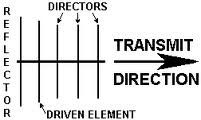
39 Yagi or beam antenna Dir. (all) Parasitic elements Driven (active) Ref. Hidetsugu Yagi, inventor in 1920s VHF, UHF: small size makes multi elements easy

40 Yagi azimuth pattern Beamwidth measured at 3 db points Yagi elevation pattern
41
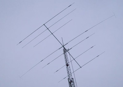
42 3-element 3-band yagi (Mosley CL-33) VERY popular 2 Traps Max radiation! λ/2-5% Boom=> λ/ meters Aircraft aluminum tubing construction Boom = 18 Elements = long Weight 40 lbs. Front:back ratio: db Forward gain: dbd dbi SWR curves for this Tri-bander Director (parasitic) Driven (active) 0.2λ spacing λ/2 +5% Min radiation! Reflector (parasitic)
43


44 Cubical Quad Directive Antenna -Quiet -Directive -Easily multi-banded

45 The cubical quad not great in wind + ice!

46 Stacked yagis after an ice storm

47 Improvised/expedition antennas -Correct wire lengths dependent on operating frequency!

48 DX-pedition antennas on 40 TV tower

49 Parabolic antennas for very high gain -High F/B ratio -Highly directional -The spotlight of the RF spectrum -Dipole, feedhorn, and preamplifier at focus -Great for UHF => up -The higher the freq., the more precise the parabola must be -Mechanically very difficult for low frequencies
 Antenna/SWR analyzer Field-strength")
50 Antenna-Related Equipment RF Power :SWR meter Artificial antenna or dummy load (pure resistance) Antenna/SWR analyzer Field-strength meter
51 Antenna Safety Climbing towers, trees, roofs -safety belt, harness for towers -safe equipment (quality ropes, ladders, etc) -at least two people! -training for tower climbing -experience for tower put-up, tear-down -quality tower components Electric shock -lightning protection for high masts, towers, aerials (good grounding, safety antenna disconnect) AVOID POWER LINES! No wire or metallic antenna parts above, below, or near commercial power lines Non-ionizing radiation (RF fields): -unclear whether any real risk to humans, but should set up station to minimize RF near radio -also tends to minimize interference on radio

52 END Of Transmission Lines and Antennas Questions??
53 END

54
55
56
Selecting Receiving Antennas for Radio Tracking
 Selecting Receiving Antennas for Radio Tracking Larry B Kuechle, Advanced Telemetry Systems, Inc. Isanti, Minnesota 55040 lkuechle@atstrack.com The receiving antenna is an integral part of any radio location
Basic Wire Antennas. Part II: Loops and Verticals
 Basic Wire Antennas Part II: Loops and Verticals A loop antenna is composed of a single loop of wire, greater than a half wavelength long. The loop does not have to be any particular shape. RF power can
Just a Dipole. Gary Wescom N0GW July 16, 2007
 Just a Dipole Gary Wescom N0GW July 16, 2007 Often we will hear people describing their antennas as just a dipole. After all, a coax cable fed, half wavelength dipole is one of the simplest antennas to
The Antenna Balun. What is this thing and why do I need it?
 What is this thing and why do I need it? The Antenna Balun In this chapter we will look at a common component in some transmission systems the balun. It is quite common to see a balun in wire antennas
40m-10m DELTA LOOP ANTENNA - GU3WHN
 This simple broad band antenna is easy to build, has gain similar to that of a dipole and is tolerant of nearby objects. It can be erected in almost any configuration provided the wires are well separated
Weekend Antennas No. 1 A Bobtail Curtain for 2m
 Weekend Antennas No. 1 A Bobtail Curtain for 2m Welcome to the first installment of my new column, which I hope will become a regular feature in Radio ZS. Each installment will present a practical and
VE3MLB Phased Double V Antenna for 75/80 Meter Band
 Jan. 17, 2008 VE3MLB Phased Double V Antenna for 75/80 Meter Band This is a story of a double inverted V antenna that I built in January 2008. I already had a full 80 meter Delta loop suspended from my
Antenna Basic Concepts
 ANTENNA An antenna is a device to transmit and/or receive electromagnetic waves. Electromagnetic waves are often referred to as radio waves. Most antennas are resonant devices, which operate efficiently
Modeling an 80/40/20M Fan Dipole for DX
 Modeling an 80/40/20M Fan Dipole for DX New Station New Antennas! Installation and SWR Response Where is the DX? How do these Dipoles Play? (EZNEC) What about Terrain? HFTA and Terrain The effect on these
LDG RBA-4:1Balun LDG RBA-1:1Balun
 LDG RBA-4:1Balun LDG RBA-1:1Balun Table of Contents Features 1 Specifications 1 Preparation 2 An important word about power levels: 2 Installation 2 Care and Maintenance 6 Technical Support 6 Warranty
5. ANTENNA TYPES. Figure 5. The vertical dipole and its electromagnetic equivalent, the vertical monopole
 Antennas can be classified in several ways. One way is the frequency band of operation. Others include physical structure and electrical/electromagnetic design. The antennas commonly used for LMR both
Technician Licensing Class
 Technician Licensing Class Antennas Presented by Amateur Radio Technician Class Element 2 Course Presentation ELEMENT 2 SUB-ELEMENTS (Groupings) About Ham Radio Call Signs Control Mind the Rules Tech Frequencies
Antenna Trainer EAN. www.edibon.com. Technical Teaching Equipment INTRODUCTION
 Antenna Trainer EAN Technical Teaching Equipment Products Products range Units 3.-Communications INTRODUCTION Antennas are the main element of aerial communications. They are the transition between a transmission
PLEASE - Read this entire booklet and study the diagrams before building a Quad, it can save you unwarranted frustrations!
 VHF/UHF Quad Antenna The information in this article has come from many amateur sources, the most notable was from WA6TEY (sk 1985) Ray Frost, who was a pioneer of VHF Quad designs and one of the best
EE302 Lesson 14: Antennas
 EE302 Lesson 14: Antennas Loaded antennas /4 antennas are desirable because their impedance is purely resistive. At low frequencies, full /4 antennas are sometime impractical (especially in mobile applications).
Antenna Glossary Before we talk about specific antennas, there are a few common terms that must be defined and explained:
 Antenna Basics Introduction Antennas are a very important component of communication systems. By definition, an antenna is a device used to transform an RF signal, traveling on a conductor, into an electromagnetic
Antenna Properties and their impact on Wireless System Performance. Dr. Steven R. Best. Cushcraft Corporation 48 Perimeter Road Manchester, NH 03013
 Antenna Properties and their impact on Wireless System Performance Dr. Steven R. Best Cushcraft Corporation 48 Perimeter Road Manchester, NH 03013 Phone (603) 627-7877 FAX: (603) 627-1764 Email: sbest@cushcraft.com
Designing Log Periodic Antennas
 Designing Log Periodic Antennas By Glen Dash, Ampyx LLC, GlenDash at alum.mit.edu Copyright 2000, 2005 Ampyx LLC Lightweight and precise, the log periodic has become a favorite among EMC engineers. In
Coaxial Cable Feeder Influence on Yagi Antenna Dragoslav Dobričić, YU1AW dragan@antennex.com
 Coaxial Cable Feeder Influence on Yagi Antenna Dragoslav Dobričić, YU1AW dragan@antennex.com Introduction o far, in several previous articles [1, 2, 3], we investigated how boom radius and its S distance
ZS6BKW vs G5RV. Antenna Patterns/SWR at 40 ft Center height, 27 ft end height ~148 Degree Included Angle
 ZS6BKW vs G5RV Antenna Patterns/SWR at 40 ft Center height, 27 ft end height ~148 Degree Included Angle Compiled By: Larry James LeBlanc 2010 For the AARA Ham Radio Club Note: All graphs computed using
Antenna Deployment Technical Brief
 ProCurve Networking Antenna Deployment Technical Brief Introduction... 2 Antenna types... 2 Omni directional antennas... 2 Directional antennas... 2 Diversity antennas... 3 High gain directional antennas...
The W5JCK Guide to the Mathematic Equations Required for the Amateur Extra Class Exam
 The W5JCK Guide to the Mathematic Equations Required for the Amateur Extra Class Exam This document contains every question from the Extra Class (Element 4) Question Pool* that requires one or more mathematical
Newcomers and Elmers Net: More Wire Antennas 02.14.16 Robert AK3Q
 Newcomers and Elmers Net: More Wire Antennas 02.14.16 Robert AK3Q Antenna Construction Supplies Antenna Construction Tools (Harbor Freight can be a good place to go) Wire Cutters; Pliers (regular and needle
Understanding SWR by Example
 Understanding SWR by Example Take the mystery and mystique out of standing wave ratio. Darrin Walraven, K5DVW It sometimes seems that one of the most mysterious creatures in the world of Amateur Radio
Invisible DX Antenna for the Low Bands
 Invisible DX Antenna for the Low Bands By Heinz-Josef Pick, DK5WL Summary This paper describes a multi-band DX antenna for the 160m-40m amateur radio bands with low visibility but great performance for
RigExpert AA-30 Antenna Analyzer (0.1 to 30 MHz) AA-54 Antenna Analyzer (0.1 to 54 MHz) User s manual
 AA-54 Antenna Analyzer (0.1 to 54 MHz) User s manual") RigExpert AA-30 Antenna Analyzer (0.1 to 30 MHz) AA-54 Antenna Analyzer (0.1 to 54 MHz) User s manual Table of contents 1. Description... 3 2. Specifications... 4 3. Precautions... 5 4. Operation... 6
RigExpert AA-30 Antenna Analyzer (0.1 to 30 MHz) AA-54 Antenna Analyzer (0.1 to 54 MHz) User s manual Table of contents 1. Description... 3 2. Specifications... 4 3. Precautions... 5 4. Operation... 6
Cellular Wireless Antennas
 Cellular Wireless Antennas A Technical Brief GarrettCom Inc., November 2010 Overview The Cellular Wireless Antenna Technical brief is provided to assist with the design and deployment of the DX940 Cellular
Antennas 101 The Basics. Ward Silver NØAX
 Antennas 101 The Basics Ward Silver NØAX The Basics - 1 Antennas radiate (or receive) because electrons are accelerated (or are caused to accelerate) in the antenna s elements Radio or electromagnetic
'' EGGBEATER '' ANTENNA VHF/UHF ~ PART 2
 '' EGGBEATER '' ANTENNA VHF/UHF ~ PART 2 ON6WG / F5VIF Summary Note : In Part 1, Fig 1 shows a maximum gain of 6.45 dbi. Several design attempts were made using slightly different configurations ( i.e.
2 Meter Half-Wave J-Pole Antenna From 450 Ohm Ladder Line
 2 Meter Half-Wave J-Pole Antenna From 450 Ohm Ladder Line Photos: Copyright 2007 David Jordan WA3GIN. All rights reserved. This is a good rainy day antenna project for those of you who would like to home
Avaya WLAN 9100 External Antennas for use with the WAO-9122 Access Point
 Avaya WLAN 9100 External Antennas for use with the WAO-9122 Access Point Overview To optimize the overall performance of a WLAN in an outdoor deployment it is important to understand how to maximize coverage
Small HF Antennas - - -- - - - -- - - ! The Small Space and Big Antenna Dilemma! Constraints
 Small HF Antennas! The Small Space and Big Antenna Dilemma! Constraints " Covenants " Restricted lot size " City Bylaws " Boards of Variance " Strata Rules " Neighbor complaints of unsightly structures
THE KW107 SUPERMATCH ATU manual, courtesy of Barry G0DWZ
 THE KW107 SUPERMATCH ATU manual, courtesy of Barry G0DWZ I ve copied the following directly from the KW107 manual without alteration. To clear up one or two ambiguous points, I have added my own comments
Antennas, Masts, Head amplifiers, Cables and Filters for a 143.050MHz Meteor Scatter Radar Receiver
 1 Introduction This article describes some options for amateur radio astronomers who wish to construct a practical, low cost receiver station to observe meteor scatter echoes from the French Graves space
ISS Minimalist Antenna
 ISS Minimalist Antenna The purpose of this project was to develop an antenna suggestion that would allow for a simple to duplicate, affordable antenna solution for reasonable access to signals transmitted
The spiderbeam was developed as a DXpeditioner's dream antenna. It is a full size lightweight tribander yagi made of fiberglass and wire.
 The spiderbeam was developed as a DXpeditioner's dream antenna. It is a full size lightweight tribander yagi made of fiberglass and wire. The whole antenna weight is only kg (lbs), making it ideally suited
JP Tribander Owner Manual
 JP Tribander Owner Manual JP-Tribander Technical overview JP-Tribander is effective tribander beam for 20m, 15m and 10meters with full size elements without traps. Antenna is designed using latest computer
EH-20 20m antenna. By VE3RGW
 EH-20 20m antenna By VE3RGW Equivalent circuit of EH-20 (prototype 2A) antenna system. Upper cylinder Lower cylinder Ground Counter pose Phasing coil Impedance transformer and tune circuit Tune coil Feed
Here are the details with pictures of the items for sale as listed below. Please Scroll Down.
 Here are the details with pictures of the items for sale as listed below. Please Scroll Down. Further Items are also available - for further list please phone or e-mail Phone Ivan 073 528 4950 or 021 439
Connecting Your Receiver to the Antenna
 TECHNOTE No. 3 Joe Carr's Radio Tech-Notes Connecting Your Receiver to the Antenna Joseph J. Carr Universal Radio, Inc. 6830 Americana Parkway Reynoldsburg, Ohio 43068 1 Connecting Your Receiver to the
Owners Manual For The PackTenna Mini
 Owners Manual For The PackTenna Mini By Nick Garner N3WG and George Zafiropoulos KJ6VU Quickstart With The 9:1 Random Wire Version You can identify this version because it has a yellow shrink wrap on the
Loop Skywire Mysteries Explained?
 Introduction: Many antenna books dismiss the horizontal loop or loop skywire as a non performer. However user s of the loop will tell you that it does work; why? I used 80 & 40m loops in the past with
RADIATION PATTERNS. The half-power (-3 db) beamwidth is a measure of the directivity of the antenna.
 beamwidth is a measure of the directivity of the antenna.") RADIATION PATTERNS The radiation pattern is a graphical depiction of the relative field strength transmitted from or received by the antenna. Antenna radiation patterns are taken at one frequency, one
RADIATION PATTERNS The radiation pattern is a graphical depiction of the relative field strength transmitted from or received by the antenna. Antenna radiation patterns are taken at one frequency, one
This Antenna Basics reference guide includes basic information about antenna types, how antennas work, gain, and some installation examples.
 Antenna Basics This Antenna Basics reference guide includes basic information about antenna types, how antennas work, gain, and some installation examples. What Do Antennas Do? Antennas transmit radio
Applications in EMC testing. Outline. Antennas for EMC Testing. Terminology
 Antennas for EMC Testing Zhong Chen ETS-Lindgren 1301 Arrow Point Drive Cedar Park, TX 78613 Zhong.Chen@ets-lindgren.com Outline EMC Terms and Definitions Typical EMC Antennas Calibration of EMC Antennas
Modeling and Measuring the Creative Design CLP5130-2N Log Periodic Antenna
 Modeling and Measuring the Creative Design CLP5130-2N Log Periodic Antenna Whitham D. Reeve 1. Introduction A log periodic antenna is an array of dipoles with mathematically related lengths and spacings.
Cheap Antennas for the AMSAT LEO's Kent Britain -- WA5VJB
 Cheap Antennas for the AMSAT LEO's Kent Britain -- WA5VJB Cheap LEO Antenna Drew, KO4MA, using the Cheap LEO antenna during a Dayton AMSAT LEO Demonstration Hand held dual band antennas are popular for
Impedance Matching and Matching Networks. Valentin Todorow, December, 2009
 Impedance Matching and Matching Networks Valentin Todorow, December, 2009 RF for Plasma Processing - Definition of RF What is RF? The IEEE Standard Dictionary of Electrical and Electronics Terms defines
End Fed Antenna. Operating Manual. version 1.1
 Cross Country Wireless (2009) Ltd, 7 Thirlmere Grove, BOLTON, BL4 0QB, UK Email chrism@crosscountrywireless.net Web page http://www.crosscountrywireless.net Telephone +44 (0) 1204 410626 Mobile GSM 900
TEST REPORT INVESTIGATION OF THE FAR-FIELD RADIATION GAIN PATTERN OF THE 20-METER BACKPACKER EH ANTENNA. 23 March 2003
 TEST REPORT INVESTIGATION OF THE FAR-FIELD RADIATION GAIN PATTERN OF THE 20-METER BACKPACKER EH ANTENNA 23 March 2003 Introduction Significant claims have been made by the inventor and producers of a novel
STACKING, PHASING and MATCHING YAGIS
 STACKING, PHASING and MATCHING YAGIS This is a synopsis of a talk presented to the Sydney VHF DX GROUP on Tuesday March 16th 1999 by Gordon McDonald VK2ZAB. QUESTIONS When the stacking of Yagis is being
40 Meter Mini-MOXON Beam Antenna. Designed, built, and presented by: Al Koblinski W7XA
 40 Meter Mini-MOXON Beam Antenna Designed, built, and presented by: Al Koblinski W7XA Design goals Some forward gain Good directivity (high F/B and F/S ratios) Relatively small size Good Bandwidth (min.
impedance is easier for the tuner to cope with across multiple bands which are related to even harmonic lengths of the dipole.
 By Ron Bertrand VK2DQ - 2007 Want to build a simple, efficient, multiband antenna? One of the best and inexpensive multiband antennas is the off-centre-fed (OCF) dipole. These are wonderfully simple antennas
Pillbox Antenna for 5.6 GHz Band Dragoslav Dobričić, YU1AW dragan@antennex.com
 Pillbox Antenna for 5.6 GHz Band Dragoslav Dobričić, YU1AW dragan@antennex.com Introduction The pillbox or cheese antenna is made of two parallel plates which are connected to the narrow strip of parabolic
An equivalent circuit of a loop antenna.
 3.2.1. Circuit Modeling: Loop Impedance A loop antenna can be represented by a lumped circuit when its dimension is small with respect to a wavelength. In this representation, the circuit parameters (generally
Electromagnetic radiation exposure: assessment against ACA mandated limits
 Electromagnetic radiation exposure: assessment against ACA mandated limits General radio services (operating above 0 MHz) (Edition May 0) Disclaimer Unless otherwise specified, the information contained
Digital Active Indoor Antenna SRT ANT 10 ECO
 Digital Active Indoor Antenna SRT ANT 10 ECO Picture similar User Manual Table of contents 1.0 INTRODUCTION 1 2.0 PACKAGE CONTENT 1 3.0 SAFETY NOTES 2 4.0 CONNECTING THE ANTENNA 2 1.0 INTRODUCTION Thank
Amplifier for Small Magnetic and Electric Wideband Receiving Antennas (model AAA-1B)
") Amplifier for Small Magnetic and Electric Wideband Receiving Antennas (model AAA-1B) 1. Description and Specifications Contents 1.1 Description 1.2 1.2 Specifications 1.3 1.3 Tested parameters in production
Amplifier for Small Magnetic and Electric Wideband Receiving Antennas (model AAA-1B) 1. Description and Specifications Contents 1.1 Description 1.2 1.2 Specifications 1.3 1.3 Tested parameters in production
HF OPERATORS SMALL HF ANTENNAS - - - - - - - - - - - Rev 1. John White VA7JW
 HF OPERATORS SMALL HF ANTENNAS Rev 1 by John White VA7JW NSARC HF Operators 1 Antenna Problems Big or Small always problems. Affects all - Single family, apartments, condo s, high rises, etc The Small
Installation Instructions Hustler 6-BTV Trap Vertical
 Installation Instructions Hustler 6-BTV Trap Vertical ASSEMBLY 1. Check the package contents against the parts list on page 2. 2. WARNING. Installation of this product near power lines is dangerous. For
FILTERS - IN RADIO COMMUNICATIONS
 Reading 32 Ron Bertrand VK2DQ http://www.radioelectronicschool.com FILTERS - IN RADIO COMMUNICATIONS RADIO SIGNALS In radio communications we talk a lot about radio signals. A radio signal is a very broad
Measurement of Antenna Radiation Patterns Laboratory Manual
 Measurement of Antenna Radiation Patterns Laboratory Manual Written by: Vishal Bhavsar Nicholas Blas Huy Nguyen Under the Guidance of: Professor Alexander Balandin Funding Provided By: TRW Corporation
MAGNETICS: FERRITES, BEADS and BALUNS
 HF OPERATORS MAGNETICS: FERRITES, BEADS and BALUNS by John White VA7JW NSARC HF Operators 1 What s the Problem?! HF Dipoles and coaxial cables have a nasty compatibility problem! Dipoles are balanced structures!
NAVICOM DYNAMICS RTK BASE STATION INSTALLATION AND COMMISSIONING INSTRUCTIONS
 NAVICOM DYNAMICS RTK BASE STATION INSTALLATION AND COMMISSIONING INSTRUCTIONS 1. Locate a suitable position inside the building to install the Base Station enclosure where mains power (240V AC) is available
Broadband Slotted Coaxial Broadcast Antenna Technology
 Broadband Slotted Coaxial Broadcast Antenna Technology Summary Slotted coaxial antennas have many advantages over traditional broadband panel antennas including much smaller size and wind load, higher
Electromagnetic radiation exposure: assessment against ACA mandated limits
 Electromagnetic radiation exposure: assessment against ACA mandated limits Paging services (Edition May 2002) Disclaimer Unless otherwise specified, the information contained in these guidelines is intended
BALUNS PART I. Andy Griffith W4ULD
 BALUNS PART I Andy Griffith W4ULD Recently I was thumbing through my files on baluns and realized that over the years I had collected a wealth of information that could be of use to fellow Hams. So, I
Embedded FM/TV Antenna System
 1 Embedded FM/TV Antenna System Final Report Prepared for By January 21, 2011 2 Table of Contents 1 Introduction... 5 2 Technical Specification... 6 3 Prototype Antenna... 7 4 FASTROAD Active module fabrication...
"EGGBEATER"ANTENNA VHF/UHF ~ PART 1
 "EGGBEATER"ANTENNA VHF/UHF ~ PART 1 ON6WG / F5VIF For the enthusiastic listeners or the licensed amateur station wishing to experiment with satellite transmissions without investing a large sum of money
My Loop Antenna. Stephen E. Sussman-Fort, Ph.D. AB2EW. stevesf@optonline.net
 Stephen E. Sussman-Fort, Ph.D. AB2EW stevesf@optonline.net Outline Brief History Characteristics of Small Loop Antennas for HF My Loop for 40m 15m Receive/Transmit Properties of Elect.-Small Loops Loop
Shielding Effectiveness Test Method. Harbour s LL, SB, and SS Coaxial Cables. Designs for Improved Shielding Effectiveness
 Shielding Effectiveness Test Method Harbour s LL, SB, and SS Coaxial Cables Designs for Improved Shielding Effectiveness Harbour Industries 4744 Shelburne Road Shelburne Vermont 05482 USA 802-985-3311
EMC STANDARDS STANDARDS AND STANDARD MAKING BODIES. International. International Electrotechnical Commission (IEC) http://www.iec.
 http://www.iec.") EMC STANDARDS The EMC standards that a particular electronic product must meet depend on the product application (commercial or military) and the country in which the product is to be used. These EMC regulatory
EMC STANDARDS The EMC standards that a particular electronic product must meet depend on the product application (commercial or military) and the country in which the product is to be used. These EMC regulatory
Siemens Energy & Automation. structured. WIRING Product Training Series: Advanced Video Session 3
 s structured WIRING Product Training Series: Advanced Video Session 3 1 Table of Contents This presentation will give you a closer look at Video in Structured Wiring applications. The following Areas will
DL-QRP-AG Lambda/2 no Counterpoise: Fuchs Antenna matching unit
 DL-QRP-AG Lambda/2 no Counterpoise: Fuchs Antenna matching unit QRPproject Molchstr. 15 12524 Berlin http://www.qrpproject.de Telefon: +49(30) 85 96 13 23 e-mail: support@qrpproject.de Handbucherstellung:
HUMAN EXPOSURE TO EMR: ASSESSMENT OF AMATEUR RADIO STATIONS FOR COMPLIANCE WITH ACA REQUIREMENTS
 HUMAN EXPOSURE TO EMR: ASSESSMENT OF AMATEUR RADIO STATIONS FOR COMPLIANCE WITH ACA REQUIREMENTS May 2005 Version 2.0 PO Box 78 BELCONNEN ACT 2616 Telephone (02) 6219 5555 Facsimile (02) 6219 5353 www.aca.gov.au
Datasheet. airmax 2x2 PtP Bridge Dish Antenna. Models: RD-2G24, RD-3G26, RD-5G30, RD-5G30-LW, RD-5G34. Powerful Performance for Long-Range Links
 airmax 2x2 PtP Bridge Dish Antenna Models: RD-2G24, RD-3G26, RD-5G30, RD-5G30-LW, RD-5G34 Powerful Performance for Long-Range Links Robust Design and Construction for Outdoor Use Seamless Integration with
Portable HF Antennas. Presented to the Stamford Amateur Radio Association. by Jon Perelstein. Copyright 2010 Jon Perelstein 1
 Portable HF Antennas Presented to the Stamford Amateur Radio Association by Jon Perelstein Copyright 2010 Jon Perelstein 1 For purposes of this presentation, a portable HF antenna is An antenna that doesn't
Boom Influence on Yagi Antenna Dragoslav Dobričić, YU1AW (Serbia) dragan@antennex.com
 dragan@antennex.com") Boom Influence on Yagi Antenna Dragoslav Dobričić, YU1AW (Serbia) dragan@antennex.com Introduction T he boom of the Yagi antenna is an inevitable part of its construction. Theoretically, Yagi antennas
Boom Influence on Yagi Antenna Dragoslav Dobričić, YU1AW (Serbia) dragan@antennex.com Introduction T he boom of the Yagi antenna is an inevitable part of its construction. Theoretically, Yagi antennas
Constructing a precision SWR meter and antenna analyzer. Mike Brink HNF, Design Technologist.
 Constructing a precision SWR meter and antenna analyzer. Mike Brink HNF, Design Technologist. Abstract. I have been asked to put together a detailed article on a SWR meter. In this article I will deal
Compact Integrated Antennas
 Freescale Semiconductor, Inc. Application Note Document Number: AN2731 Rev. 3, 09/2015 Compact Integrated Antennas Designs and Applications for the MC1321x, MC1322x, MC1323x, and MKW40/30/20 1 Introduction
Current Probes. User Manual
 Current Probes User Manual ETS-Lindgren L.P. reserves the right to make changes to any product described herein in order to improve function, design, or for any other reason. Nothing contained herein shall
Single Transistor FM Transmitter Design
 Single Transistor FM Transmitter Design In telecommunications, frequency modulation (FM) conveys information over a carrier wave by varying its frequency. FM is commonly used at VHF radio frequencies for
The VHF / UHF «Eggbeater» Antenna ~ Revisited ~
 The VHF / UHF «Eggbeater» Antenna ~ Revisited ~ ON6WG / F5VIF A new simple way to build the Eggbeater Antenna Introduction Previous designs described in «VHF / UHF «Eggbeater» Antenna ~ Part 1» and «VHF
Dummies guide to aircraft antennas
 Dummies guide to aircraft antennas Probably the single biggest issue that we encounter with the installation of our XCOM radios by customers in the field is poor antenna performance. Most customers are
Cheap Yagi Antennas for VHF/UHF
 Cheap Yagi Antennas for VHF/UHF by Kent Britain, WA5VJB edited by John Maca, AB5SS [Editors notes: The antennas described in this article were built as the result of several discussions between Kent and
Study of RF Spectrum Emissions in High Pressure Sodium and Metal Halide Lamps. Lawrence P. Glaister VE7IT, Automation Engineer.
 Study of RF Spectrum Emissions in High Pressure Sodium and Metal Halide Lamps Lawrence P. Glaister VE7IT, Automation Engineer May 2010 Abstract: This research was performed in collaboration with the City
An octave bandwidth dipole antenna
 An octave bandwidth dipole antenna Abstract: Achieving wideband performance from resonant structures is challenging because their radiation properties and impedance characteristics are usually sensitive
NVIS ANTENNA THEORY AND DESIGN
 NVIS ANTENNA THEORY AND DESIGN Introduction A properly designed Near Vertical Incident Skywave (NVIS) antenna will have a directivity pattern that will maximize transmission and reception at high angles
Flexible PCB Antenna with Cable Integration Application Note Version 2
 Flexible PCB Antenna with Cable Integration Application Note Version 2 CONTENTS 1. BASICS 2. APPLICATIONS 3. SIZE 4. SHAPE 5. GROUND PLANE SIZE 6. IMPEDANCE 7. BANDWIDTH 8. VSWR 9. GAIN 10. EFFICIENCY
Selecting a Transmission Line for Your Broadcast System
 Selecting a Transmission Line for Your Broadcast System Introduction This Bulletin presents the procedures broadcasters need for calculating attenuation and power handling parameters to properly design
Internal GPS Active Patch Antenna Application Note
 Internal GPS Active Patch Antenna Application Note APN-13-8-002/A Page 1 of 14 1. BASICS 2. APPLICATIONS 3. SIZE 4. SHAPE 5. GROUND PLANE 6. IMPEDANCE 7. BANDWIDTH 8. VSWR 9. LINK BUDGET 10. GAIN 11. NOISE
Sensor and Simulation Notes. Note 479. October 2003. A Dual-Polarity Impulse Radiating Antenna
 Sensor and Simulation Notes Note 479 October 2003 A Dual-Polarity Impulse Radiating Antenna Leland H. Bowen and Everett G. Farr Farr Research, Inc. Dean I. Lawry Air Force Research Laboratory, Directed
2/20/2009 3 Transmission Lines and Waveguides.doc 1/3. and Waveguides. Transmission Line A two conductor structure that can support a TEM wave.
 2/20/2009 3 Transmission Lines and Waveguides.doc 1/3 Chapter 3 Transmission Lines and Waveguides First, some definitions: Transmission Line A two conductor structure that can support a TEM wave. Waveguide
Common Mode Choke Filtering Improves CMRR in Ethernet Transformer Applications. Application Note. June 2011
 Common Mode Choke Filtering Improves CMRR in Ethernet Transformer Applications June 2011 Application Note Common mode chokes provide an effective EMI filtering solution for Ethernet transformer applications.
Omni Antenna vs. Directional Antenna
 Omni Antenna vs. Directional Antenna Document ID: 82068 Contents Introduction Prerequisites Requirements Components Used Conventions Basic Definitions and Antenna Concepts Indoor Effects Omni Antenna Pros
Minimum requirements for DVB-T receiving antennas for portable indoor and portable outdoor reception
 Deutsche TV Platform Minimum requirements for DVB-T receiving antennas for portable indoor and portable outdoor reception compiled by Working Group: DVB-T launch (a working group of the Deutsche TV Platform)
My Top Five Backyard Multi-Band Wire HF Antennas
 My Top Five Backyard Multi-Band Wire HF Antennas L. B. Cebik, W4RNL 1434 High Mesa Drive Knoxville, TN 37938-4443 e-mail: cebik@cebik.com 2004 marks my fifth full decade as a licensed radio amateur. So
Coaxial Transmitting Chokes
 Coaxial Transmitting Chokes Jim Brown K9YC Santa Cruz, CA http://audiosystemsgroup.com Understanding Common Mode and Differential Mode Currents on Transmission Lines 1 Differential Mode Current Transmission
HMS Hairpin Matching Systems
 HMS Hairpin Matching Systems DXE-HMS-1P, DXE-HMS-2P, DXE-HMS-4P DXE-HMS-INS-Rev 1b For Use with 1-1/2 Inch through 3 Inch Booms Shown with optional boom, elements and Element Bracket with hardware DX Engineering
Advanced RF Isolation Variable Beamwidth Antenna. Datasheet. Model: AM-V5G-Ti. Carrier-Class 2x2 MIMO PtMP BaseStation
 Advanced RF Isolation Variable Beamwidth Antenna Model: AM-V5G-Ti Carrier-Class 2x2 MIMO PtMP BaseStation Adjustable Beamwidth Configuration Reduced Co-Location Interference Advanced Carrier-Class PtMP