Seismic Code Provisions (Geotechnical Considerations)
|
|
|
- Hannah Welch
- 9 years ago
- Views:
Transcription
1 Seismic Code Provisions (Geotechnical Considerations) University of California, San Diego 1 Main References R. Dobry, R.D. Borcherdt, C. B. Crouse, I. M. Idriss, W. B. Joyner, G. R. Martin, M. S. Power, E. E. Rinne, and R. B. Seed, New Site Coefficients and Site Classification System Used in Recent Building Seismic Code Provisions, Earthquake Spectra, Volume 16, No. 1, February C.B. Crouse, E.V. Leyendecker, P.G. Somerville, M. Power, and W.J. Silva, development of seismic groundmotion criteria for the ASCE 7 standard, Proceedings of the 8th U.S. National Conference on Earthquake Engineering April 18-22, 2006, San Francisco, California, USA, Paper No American Society of Civil Engineers (ASCE), Minimum Design Loads for Buildings and Other Structures, ASCE Standard ASCE/SEI Building Seismic Safety Council, (BSSC), 2004a. NEHRP Recommended Provisions for Seismic Regulations for New Buildings and Other Structures, FEMA 450-1/2003 Edition, Part 1: Provisions. Building Seismic Safety Council, (BSSC), 2004b. NEHRP Recommended Provisions for Seismic Regulations for New Buildings and Other Structures, FEMA 450-2/2003 Edition, Part 2: Commentary. 2
2 Site Response Effects (From Dobry et al. 2000) 3 (From Dobry et al. 2000) 4
3 Historical Background ATC 1978 Three distinct site coefficients S 1 -S 3 (include soil type and depth) based on Statistical Studies by Seed and co-workers (1976) and Mohraz (1976). Experience from the 1985 Mexico City Earthquake resulted in the addition of a fourth site category S 4 with a higher value to account for deep soft clay deposits. Each S value was associated with a different spectral shape The S value only amplified the long period part of the Spectrum 5 (From Dobry et al. 2000) 6
4 (From Dobry et al. 2000) 7 (From Dobry et al. 2000) 8
5 New Developments Mexico city (1985) and Loma Prieta (1989) earthquakes (among other studies) showed that the effect of the level of shaking (low levels of peak ground acceleration and low spectral levels at short periods can be significantly amplified at soft sites (Idriss and Fig. 1). New York City studies (e.g., Jacob 1990, 1994) introduced two new key aspects: 1. Higher values of site coefficients (due to low excitation levels) 2. Addition of hard rock category to account for much stiffer rock in the eastern US (compared to CA). 9 Fig. 1: Average spectra recorded during 1989 Loma Prieta Earthquake in San Francisco Bay Area at rock sites and soft soil sites (modified after Housner 1990) (From Dobry et al. 2000) 10
6 New Developments NCEER Workshop (Whitman 1992) with 9 members (authors of Dobry et al paper) Los Angeles Workshop (Martin 1994) with 65 invited geoscientists, geotechnical and structural engineers developed consensus recommendations incorporated in the 1994 and 1997 NEHRP Provisions and 1997 UBC provisions 11 Peak Acc on Rock g amplified 2-3 times to 0.2g 0.3g at soft soil sites Spectral ordinates at short periods (T =0.2 0r 0.3 seconds) were also amplified by factors of 2 or 3 Fig. 2 shows amplification of response spectra between nearby rock and soil sites (Ratio of Response Spectra or RRS) Both Figs. 1 and 2 show that amplification at T of 0.5 to 1.5 or 2 seconds is even greater than at shorter periods with RRS ranging from 3 to 6. Similar amplification characteristics (with lower values) was also observed between rock and stiff soil sites. 12
7 Average RRS curves, Loma Prieta earthquake. Curves show geometric average and plus and minus 1 standard deviation. Vertical lines show range (note log scale), (after Joyner et al. 1994). At some of these sites, amplification occurred at long periods seemingly related to the characteristics of the soil deposit (Fig. 2, From Dobry et al. 2000) 13 Profile of representative instrumented soft clay site, 70 km north Of epicenter, RSS max about 3.5 at T of about 1.4 second. In other extreme (but unusual) cases (Mexico city), at T of about 2 3 sec. RSS max ranged from 3 to 20. (From Dobry et al. 2000) Fig. 3: Soil profile at instrumented soft clay site with a 1989 Loma Prieta earthquake record. 14
8 Code Provisions Site Classes Old Four S 1 -S 4 New Six site classes (A F) in terms of representative average shear wave velocity to a depth of 30 m ( ) SPT or S u may be used instead of A: Hard Rock = B: Rock C: Soft rock and very stiff / very dense soil D: stiff soil E: Soft soil F: Requires site-specific evaluation 100 ft or 30.5 m (d i /v si ) (d i /v si ) 15 (From Dobry et al. 2000) 16
9 (From Dobry et al. 2000) 17 Code Provisions Site amplification factors Old S v factor No short period amplification factor New F a for short periods F v for longer periods 18
10 New Site Amplification Coefficients Both F a and F v are functions of site class (A-F) AND level of seismic hazard on rock (Intensity of Rock Motions) defined by parameters such as: A a and A v (1994 NEHRP provisions, available in Seismic maps) Z (1997 UBC, based on seismic zone maps for Z in the US) S s and S l (1997 NEHRP provisions, IBC 2006) NEHRP: National Earthquake Hazards Reduction Program UBC: Uniform Building Code IBC: International Building code F a and F v decrease with the increase of seismic hazard on rock due to soil non-linearity. Greatest impact of F a and F v compared to the old S factors is in the area of low-medium seismic hazard 19 (From Dobry et al. 2000) 20
11 (NEHRP 1997) 21 (from Dobry et al. 2000) 22
12 Codes only set minimum standards and are intended to help prevent catastrophic failures NEHRP 1994 (National Earthquake Hazard Reduction Program) Seismic Base Shear V = C s W C s = 1.2 A v F v / ( R T 2/3 ) Not to exceed W = Total seismic load (combination of dead and live loads ) R = Ductility factor T = Fundamental Period of Structure (see Code for suggested formulae) C s = 2.5 A a F a / R A a and A v are available from seismic Hazard maps for particular location of interest 23 Codes only set minimum standards and are intended to help prevent catastrophic failures Static Force Procedure (Uniform Building Code 1997) The total design base shear (V) shall be determined from V = ( (C v I ) / R T ) W V < ( (2.5 C a I ) / R ) W V > 0.11 C a I W W = Total seismic load (combination of dead and live loads ) I = Seismic Importance Factor 1.25 > I > 1.0 R = Ductility factor 8.5 > R > 2.2 T = Fundamental Period of Structure For seismic zone 4 (highly seismic zone) V > ( ( 0.8 Z N v I ) / R ) W Z= seismic zone factor = 0.4, N v = Near source factor > 1.0 (15 Km away) and < 2 (2 Km away), and depends on seismic source type 24
13 UBC UBC 1997 Note that C a and C v are the equivalent of A a F a and A v F v in NEHRP 26
14 UBC UBC
15 Codes only set minimum standards and are intended to help prevent catastrophic failures Static Force Procedure (IBC 2006) The total design base shear (V) shall be determined from V = C s W, and with C s not to exceed: For T < T L For T > T L (Crouse et al. 2006) C C C s s s S DS R I SD1 R T I SD1TL 2 R T I W = Total seismic load (combination of dead and live loads ) I = Seismic Importance Factor 1.5 > I > 1.0 R = Ductility factor 8.0 > R > 1.25 T = Fundamental Period of Structure 29 S DS F S 3 Fa SS D1 v 1 (after IBC 2006) S 30
16 Check on minimum value of C s Cs shall not be less than C s 0.01 In addition, for structures located where S 1 (the one-second period spectral acceleration) is equal to or greater than 0.6g, C s shall not be less than (to implicitly account for near source effects): 0.5 S1 C s R I 31 Site Coefficient, F a Mapped Maximum Considered Earthquake Spectral Response Acceleration Parameter at Short Period Site Class S S S S = 0.5 S S = 0.75 S S = 1.0 S S A B C D E F Site Specific Ground Motions investigation Site Coefficient, F v Mapped Maximum Considered Earthquake Spectral Response Acceleration Parameter at 1-s Period Site Class S 1 S 1 = 0.2 S 1 = 0.3 S 1 = 0.4 S 1 A B C D E F Site Specific Ground Motions Investigation (after IBC 2006) 32
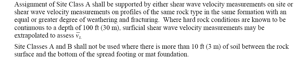
17 Site Classes The site soil shall be classified in accordance with the Table below based on the upper 100 ft (30 m) of the site profile. v is the average shear wave velocity in the upper 100 ft of the site profile and is calculated as: s n v i s n i1 si (after IBC 2006) di 1 d i is the thickness of any layer between 0 and 100 ft (30 m). di v si is the shear wave velocity in ft/s (m/s). v Where the soil properties are not known in sufficient detail to determine the site class, Site Class D shall be used unless the authority having jurisdiction or geotechnical data determines Site Class E or F soils are present at the site. Site Classes A and B shall not be assigned to a site if there is more than 10 ft of soil between the rock surface and the bottom of the spread footing or mat foundation. 33 N ~ Average Field Standard Penetration Resistance, and N ~ ch Average Standard Penetration Resistance for Cohesionless Soil Layers, shall be determined in accordance with the following formulas: ~ N n i1 n i1 d d N i i i and ~ N ch m i1 d s d N i i where N i and d i are for cohesionless soil layers only and m d i i1 where d s is the total thickness of cohesionless soil layers in the top 100 ft (30 m). N i is the standard penetration resistance (ASTM D1586) not to exceed 100 blows/ft (328 blows/m) as directly measured in the field without corrections. Where refusal is met for a rock layer, N i shall be taken as 100 blows/ft (328 blows/m). (after IBC 2006) 34 d s
18 s u is the Average Undrained Shear Strength. u shall be determined in accordance with the following formula: s u k where and, i1 d c d s i ui k d i i1 d c d c = the total thickness of cohesive soil layers in the top 100 ft (30 m) PI = the plasticity index as determined in accordance with ASTM D4318 w = the moisture content in percent as determined in accordance with ASTM D2216 s ui = the undrained shear strength in psf (kpa), not to exceed 5,000 psf (240 kpa) as determined in accordance with ASTM D2166 or ASTM D2850 (after IBC 2006) To determine S s and S 1 go to (or see maps in the Code): s 35 36
19
20 Additional Background (Geotechnical Considerations) (From Dobry et al. 2000) 39 (From Dobry et al. 2000) 40
21 (From Dobry et al. 2000) 41 (From Dobry et al. 2000) 42
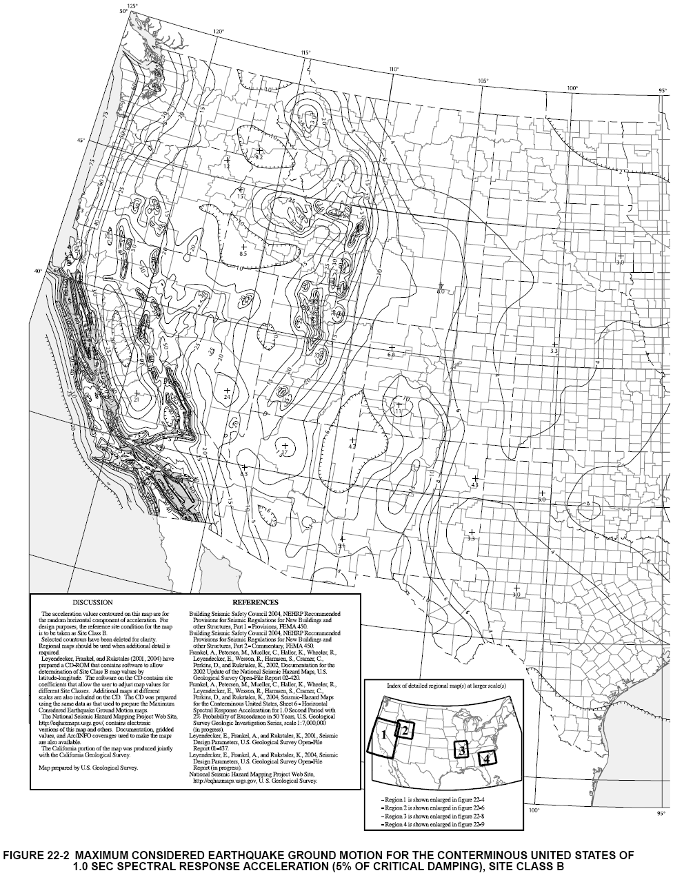
22 International Building Code 2006 Section 1613 Earthquake Loads Note: see original reference (the 2006 IBC Code) for full details The Code specifies that Every structure, and portion thereof, including nonstructural components that are permanently attached to structures and their supports and attachments, shall be designed and constructed to resist the effects of earthquake motions in accordance with ASCE 7 (ASCE SEI 7-05, see Appendix 1). As such, buildings and other structures shall be designed to sustain local damage with the structural system as a whole remaining stable (i.e., the Seismic Code ultimately aims to avoid catastrophic collapse of the structure). Base Shear per ASCE/SEI 7-05 EQUIVALENT LATERAL FORCE (ELF) Procedure The following method follows the provisions of the ASCE/SEI 7-05 and may be utilized for determining the seismic base shear. Calculation of the Seismic Base Shear, V - The seismic base shear, V, in a given direction shall be determined in accordance with the following equation: V C W (12.8-1) s where, C s is the seismic response coefficient, and W is the effective seismic weight. Evaluation of Effective Seismic Weight, W see Appendix 2 Determination of the Seismic Response Coefficient C s The seismic response coefficient, C s, is defined by: S DS Cs (12.8-2) R I where, S DS = design, 5 percent damped, spectral response acceleration parameter at short periods (Figure 1), 1
23 I is the occupancy importance factor, as shown in Appendix 3, and R is the response modification factor determined from Table (see Appendix 4). Check the value of C s versus the Need-Not-Exceed Limits - The value of C s computed in accordance with Eq need not exceed the following (see Figure 1): For T TL : C s S D1 R T I (12.8-3) For T TL : C s S D1 TL (12.8-4) 2 R T I where S D1 = design, 5 percent damped, spectral response acceleration parameter at a building Period T (see Appendix 5) of 1 second (Figure 1). Figure 1: Design Response Spectrum Configuration (from the 2006 IBC). Note: T 0 = 0.2(S D1 /S DS ), and S a at T = 0 is S DS /2.5. 2
24 In the above, T S = S D1 / S DS and T L is specified as described in Appendix 6. In the Design Response Spectrum above, the spectral response acceleration segments are specified on the basis of geotechnical site amplification studies that show overall envelopes/averages that resemble the configuration depicted in Figure 1. Check on minimum value of C s - Cs shall not be less than: C 0.01 (12.8-5) s In addition, for structures located where S 1 (the one-second period spectral acceleration, see Appendix 7) is equal to or greater than 0.6g, C s shall not be less than (to implicitly account for near source effects): 0.5 S1 C s R I (12.8-6) Determination of S DS and S D1 These spectral values are defined by the following expressions: 2 S DS S MS 3 (11.4-3) 2 S D1 S M 1 3 (11.4-4) where, M denotes Maximum Considered Earthquake (MCE), an expression that represents ground motions with a 2% probability of being exceeded in 50 years (average return period of approximately 2,500 years); with exceptions where deterministic estimates govern the MCE design motions in certain higher seismic regions near active faults (Crouse et al. 2006). S MS is the MCE, 5 percent damped, spectral response acceleration at short periods adjusted for Site Class effects, and S M1 is the MCE, 5 percent damped, spectral response acceleration at a Period of 1.0 second adjusted for Site Class effects. These spectral accelerations are defined by: 3
25 S F S (11.4-1) S MS a s M1 Fv S 1 (11.4-2) where the site-specific short period (S s ) and one-second period (S 1 ) spectral accelerations are defined following the procedures in Appendix 7, and the Site coefficients F a and F v are defined in Tables and below, respectively. Table Site Coefficient, F a (see Appendix 8 for site Class) Mapped Maximum Considered Earthquake Spectral Response Acceleration Parameter at Short Period Site Class S S 0.25 S S = 0.5 S S = 0.75 S S = 1.0 S S 1.25 A B C D E F See Section (see Appendix 9) Table Site Coefficient, F v (see Appendix 8 for site Class) Mapped Maximum Considered Earthquake Spectral Response Acceleration Parameter at 1-s Period Site Class S S 1 = 0.2 S 1 = 0.3 S 1 = 0.4 S A B C D E F See Section (see Appendix 9) Vertical Distribution of Seismic Forces The lateral seismic force (F x ) (kip or kn) induced at any level shall be determined, in accordance with ASCE/SEI 7-05 Section , from the following equations: Fx CvxV ( ) and 4
26 C vx n w h i1 x k x w h k i i ( ) where, C vx = vertical distribution factor, w i and w x = the portion of the total effective seismic weight of the structure (W) located or assigned to Level i or x, h i and h x = the height (ft or m) from the base to Level i or x, n = total number of stories, k = an exponent related to the structure period as follows: for structures having a period of 0.5 s or less, k = 1, for structures having a period of 2.5 s or more, k = 2, for structures having a period between 0.5 and 2.5 s, k shall be 2 or shall be determined by linear interpolation between 1 and 2. Horizontal Distribution of Forces - The seismic design story shear in any story (V x ) (kip or kn) shall be determined, in accordance with ASCE/SEI 7-05 Section , from the following equation: n V ( ) x F i ix where F i is the portion of the seismic base shear (V) (kip or kn) induced at Level i. Determination the Seismic Design Category For Material Design Sections of the Code Appendix 10 see The Seismic Design Category classification is employed for additional code considerations as shown in Appendix 4. References C.B. Crouse, E.V. Leyendecker, P.G. Somerville, M. Power, and W.J. Silva, development of seismic ground-motion criteria for the ASCE 7 standard, Proceedings of the 8th U.S. National Conference on Earthquake Engineering April 18-22, 2006, San Francisco, California, USA, Paper No. 533). 5
27 Appendix 1 -- Excerpts from ASCE SEI 7-05 ASCE/SEI 7-05 Minimum Design Loads for Buildings and Other Structures 1.1 SCOPE - This standard provides minimum load requirements for the design of buildings and other structures that are subject to building code requirements. Loads and appropriate load combinations, which have been developed to be used together, are set forth for strength design and allowable stress design. For design strengths and allowable stress limits, design specifications for conventional structural materials used in buildings and modifications contained in this standard shall be followed Serviceability - Buildings and other structures, and all parts thereof, shall be designed and constructed to support safely the factored loads in load combinations defined in this document without exceeding the appropriate strength limit states for the materials of construction. Alternatively, buildings and other structures, and all parts thereof, shall be designed and constructed to support safely the nominal loads in load combinations defined in this document without exceeding the appropriate specified allowable stresses for the materials of construction. 1.4 GENERAL STRUCTURAL INTEGRITY - Buildings and other structures shall be designed to sustain local damage with the structural system as a whole remaining stable and not being damaged to an extent disproportionate to the original local damage. This shall be achieved through an arrangement of the structural elements that provides stability to the entire structural system by transferring loads from any locally damaged region to adjacent regions capable of resisting those loads without collapse. This shall be accomplished by providing sufficient continuity, redundancy, or energy-dissipating capacity (ductility), or a combination thereof, in the members of the structure. C1.3 BASIC REQUIREMENTS C1.3.1 Strength - Buildings and other structures must satisfy strength limit states in which members are proportioned to carry the design loads safely to resist buckling, yielding, fracture, and so forth. It is expected that other standards produced under consensus procedures and intended for use in connection with building code requirements will contain recommendations for resistance factors for strength design methods or allowable stresses (or safety factors) for allowable stress design methods. C1.3.2 Serviceability - In addition to strength limit states, buildings and other structures must also satisfy serviceability limit states that define functional performance and behavior under load and include such items as deflection and vibration. In the United States, strength limit states have traditionally been specified in building codes because they control the safety of the structure. Serviceability limit states, on the other hand, are usually non-catastrophic, define a level of quality of the structure or element, and are a matter of judgment as to their application. Serviceability limit states involve the perceptions and expectations of the owner or user and are a contractual matter between the owner or user and the designer and builder. It is for these reasons, and because the benefits are often subjective and difficult to define or quantify, that serviceability limit states for the most part are not included within the model United States Building Codes. The fact that serviceability limit states are usually not codified should not diminish their importance. Exceeding a serviceability limit state in a building or other structure usually means that its function is disrupted or impaired because of local minor damage or deterioration or because of occupant discomfort or annoyance. 6
28 Appendix Calculate the Effective Seismic Weight, W The effective seismic weight shall include the total dead load and other loads listed below: 1. In areas used for storage, a minimum of 25 percent of the floor live load (floor live load in public garages and open parking structures need not be included). 2. Where provision for partitions is required by Section in the floor load design, the actual partition weight or a minimum weight of 10 psf (0.48 kn/m 2 ) of floor area, whichever is greater. 3. Total operating weight of permanent equipment. 4. Where the flat roof snow load, P f, exceeds 30 psf (1.44 kn/m 2 ), 20 percent of the uniform design snow load, regardless of actual roof slope. 7
29 Appendix 3 Determination of the Building s Importance Factor, I The Importance Factor I is a factor assigned to each structure according to its Occupancy Category. In turn, the Occupancy Category is defined as follows: Building s Occupancy Category - Buildings and other structures shall be classified, based on the nature of occupancy, according to Table 1-1 for the purposes of applying flood, wind, snow, earthquake, and ice provisions. The occupancy categories range from I to IV, where Occupancy Category I represents buildings and other structures with a low hazard to human life in the event of failure and Occupancy Category IV represents essential facilities. Each building or other structure shall be assigned to the highest applicable occupancy category or categories. Assignment of the same structure to multiple occupancy categories based on use and the type of load condition being evaluated (e.g., wind or seismic) shall be permissible. OCCUPANCY: The purpose for which a building or other structure, or part thereof, is used or intended to be used. The Occupancy Category is determined from Table 1-1 OCCUPANCY CATEGORY OF BUILDINGS AND OTHER STRUCTURES FOR FLOOD, WIND, SNOW, EARTHQUAKE, AND ICE LOADS. 8
30 On this basis, the importance factor, I, shall be assigned to each structure by: Occupancy Category Importance Factor, I I 1.0 II 1.0 III 1.25 IV 1.5 Note: The NEHRP 1997 Provisions in Section 1.1, identifies two purposes of the Occupancy Importance Factor, one of which specifically is to improve the capability of essential facilities and structures containing substantial quantities of hazardous materials to function during and after design earthquakes. This is achieved by introducing the occupancy importance factor of 1.25 for Seismic Use Group III structures and 1.5 for Seismic Use Group IV structures. The NEHRP Commentary Sections 1.4, 5.2, and explain that the factor is intended to reduce the ductility demands and result in less damage. When combined with the more stringent drift limits for such essential or hazardous facilities the result is improved performance of such facilities. 9
31 Appendix 4 -- R factor; and Seismic Design Category (see Appendix 10) 10
32 11
33 In this table, the overstrength factor, 0, dictates increase in seismic load for the critical structural elements that would be expected to remain in the elastic state (e.g., to prevent collapse), and the deflection amplification factor, C d dictates increases to the code-derived deflections, to be representative of the actual expected peak deflection values (since the Code specifies much lower forces to calculate building shear forces). 12
34 Determination of Design Coefficients and Factors for Building s Seismic Force-Resisting System(s) The structural system used shall be in accordance with the Seismic Design Category and height limitations indicated in Table above. The appropriate response modification coefficient, R, system overstrength factor, 0, and the deflection amplification factor, C d, indicated in Table shall be used in determining the base shear, element design forces, and design story drift. Different seismic force resisting systems are permitted to be used to resist seismic forces along each of the two orthogonal axes of the structure. Where different systems are used, the respective R, C d, and 0 coefficients shall apply to each system, including the limitations on system use contained in Table above. Where different seismic force resisting systems are used in combination to resist seismic forces in the same direction of structural response, other than those combinations considered as dual systems, the more stringent system limitation contained in Table shall apply and the design shall comply with the requirements of this section. 13
35 Appendix 5 Determination of the Approximate Fundamental Period of Structure The approximate fundamental period (T a ), in seconds, shall be determined from the following equation: T C h (12.8-7) a t x n where h n is the height in ft above the base to the highest level of the structure and the period coefficients C t and x are determined from Table TABLE VALUES OF APPROXIMATE PERIOD PARAMETERS C t AND x Structural Type C t x Moment-resisting frame systems in which the frames resist 100% of the required seismic force and are not enclosed or adjoined by components that are more rigid and will prevent the frames from deflecting where subjected to seismic forces: Steel moment-resisting frames 0.28 (0.0724)* Concrete moment-resisting frames (0.0466)* Eccentrically braced steel frames 0.03 (0.0731)* All other structural systems 0.02 (0.0488)* * Metric equivalents are shown in parentheses For structures not exceeding 12 stories in height in which the seismic force resisting system consists entirely of concrete or steel moment resisting frames and the story height is at least 10 ft, it is permitted to determine the approximate fundamental period (Ta), in s, from the following equation: T a = 0.1 N (12.8-8) where N = number of stories. 14
")
36 Appendix 6 -- Map for obtaining T L (please see sample map below) 15
37 Appendix 7 Determination of S S and S 1 (site-specific short period and one-second period spectral accelerations) S S = mapped MCE, 5 percent damped, spectral response acceleration at short periods (0.2 seconds). S 1 = mapped MCE, 5 percent damped, spectral response acceleration at a period of 1 second. The above parameters are readily available for Site Class B (see Site Classes in Appendix 8): For values over the Internet, go to: 16

38 17
.")
39 Conversely, maps (see samples below) are available in the Code (Figs through 22-14, see sample maps on the following pages). 18

40 19
41 20

42 21
43 Appendix 8 -- Site Class 5. Determination of Site Classification - Based on the site soil properties, the site shall be classified as Site Class A, B, C, D, E, or F in accordance with Chapter 20. The site soil shall be classified in accordance with Table and Section 20.3 based on the upper 100 ft (30 m) of the site profile. Where the soil properties are not known in sufficient detail to determine the site class, Site Class D shall be used unless the authority having jurisdiction or geotechnical data determines Site Class E or F soils are present at the site. Site Classes A and B shall not be assigned to a site if there is more than 10 ft of soil between the rock surface and the bottom of the spread footing or mat foundation. vs is the average shear wave velocity in the upper 100 ft of the site profile and is calculated as: v n i1 s n i1 d d v i i si d i is the thickness of any layer between 0 and 100 ft (30 m). v si is the shear wave velocity in ft/s (m/s). (20.4-1) N ~ Average Field Standard Penetration Resistance and N ~ ch, Average Standard Penetration Resistance for Cohesionless Soil Layers. N ~ and N ~ ch shall be determined in accordance with the following formulas: ~ N n i1 n i1 d d N i i i (20.4-2) 22
44 ~ N ch m i1 d s d N i i (20.4-3) where N i and d i in Eq are for cohesionless soil layers only and m di i1 d s where d s is the total thickness of cohesionless soil layers in the top 100 ft (30 m). N i is the standard penetration resistance (ASTM D1586) not to exceed 100 blows/ft (328 blows/m) as directly measured in the field without corrections. Where refusal is met for a rock layer, N i shall be taken as 100 blows/ft (328 blows/m). su is the Average Undrained Shear Strength. u formula: s shall be determined in accordance with the following s u k d c d i1 s i ui (20.4-4) where k di i1 d c and d c = the total thickness of cohesive soil layers in the top 100 ft (30 m) PI = the plasticity index as determined in accordance with ASTM D4318 w = the moisture content in percent as determined in accordance with ASTM D2216 s ui = the undrained shear strength in psf (kpa), not to exceed 5,000 psf (240 kpa) as determined in accordance with ASTM D2166 or ASTM D

45 Appendix 9 -- Site Specific Procedure 24
46 Note: Material below is from the 2003 Seismic Code Provisions 25
47 26
48 27
49 Appendix 10 Determination of the Seismic Design Category The Seismic Design Category is a classification assigned to a structure based on its Occupancy Category (Appendix 3) and the severity of the design earthquake ground motion at the site. Seismic Design Category is an important parameter in the material design sections of the Code (Appendix 4). Occupancy Category I, II, or III structures located where the mapped spectral response acceleration parameter at 1-s period, S 1, is greater than or equal to 0.75 g (Appendix 7) shall be assigned to Seismic Design Category E. Occupancy Category IV structures located where the mapped spectral response acceleration parameter at 1-s period, S 1 (Appendix 7), is greater than or equal to 0.75 g shall be assigned to Seismic Design Category F. All other structures shall be assigned to a Seismic Design Category based on their Occupancy Category and the design spectral response acceleration parameters, S DS and S D1. Each building and structure shall be assigned to the more severe Seismic Design Category in accordance with Table or , irrespective of the fundamental period of vibration of the structure, T (Appendix 5). A geotechnical investigation report shall be provided for a structure assigned to Seismic Design Category C, D, E, or F. TABLE SEISMIC DESIGN CATEGORY BASED ON SHORT PERIOD RESPONSE ACCELERATION PARAMETER Occupancy Category Value of S DS I or II III IV S DS < A A A S DS < 0.33 B B C 0.33 S DS < 0.50 C C D 0.50 S DS D D D TABLE SEISMIC DESIGN CATEGORY BASED ON 1-S PERIOD RESPONSE ACCELERATION PARAMETER Occupancy Category Value of S DS I or II III IV S D1 < A A A S D1 < B B C S D1 < 0.20 C C D 0.20 S D1 D D D 28
CH. 2 LOADS ON BUILDINGS
 CH. 2 LOADS ON BUILDINGS GRAVITY LOADS Dead loads Vertical loads due to weight of building and any permanent equipment Dead loads of structural elements cannot be readily determined b/c weight depends
FOUNDATION DESIGN. Instructional Materials Complementing FEMA 451, Design Examples
 FOUNDATION DESIGN Proportioning elements for: Transfer of seismic forces Strength and stiffness Shallow and deep foundations Elastic and plastic analysis Foundation Design 14-1 Load Path and Transfer to
Critical Facility Round Table
 Critical Facility Round Table October 16, 2003 San Francisco Seismic Risk for Data Centers David Bonneville Senior Principal Degenkolb Engineers San Francisco, California Presentation Outline Seismic Risk
Prepared For San Francisco Community College District 33 Gough Street San Francisco, California 94103. Prepared By
 Project Structural Conditions Survey and Seismic Vulnerability Assessment For SFCC Civic Center Campus 750 Eddy Street San Francisco, California 94109 Prepared For San Francisco Community College District
Miss S. S. Nibhorkar 1 1 M. E (Structure) Scholar,
 Scholar,") Volume, Special Issue, ICSTSD Behaviour of Steel Bracing as a Global Retrofitting Technique Miss S. S. Nibhorkar M. E (Structure) Scholar, Civil Engineering Department, G. H. Raisoni College of Engineering
Volume, Special Issue, ICSTSD Behaviour of Steel Bracing as a Global Retrofitting Technique Miss S. S. Nibhorkar M. E (Structure) Scholar, Civil Engineering Department, G. H. Raisoni College of Engineering
Chapter 3 DESIGN AND CONSTRUCTION FEATURES IMPORTANT TO SEISMIC PERFORMANCE
 Chapter 3 DESIGN AND CONSTRUCTION FEATURES IMPORTANT TO SEISMIC PERFORMANCE To satisfy the performance goals of the NEHRP Recommended Seismic Provisions, a number of characteristics are important to the
1997 Uniform Administrative Code Amendment for Earthen Material and Straw Bale Structures Tucson/Pima County, Arizona
 for Earthen Material and Straw Bale Structures SECTION 70 - GENERAL "APPENDIX CHAPTER 7 - EARTHEN MATERIAL STRUCTURES 70. Purpose. The purpose of this chapter is to establish minimum standards of safety
SEISMIC DESIGN. Various building codes consider the following categories for the analysis and design for earthquake loading:
 SEISMIC DESIGN Various building codes consider the following categories for the analysis and design for earthquake loading: 1. Seismic Performance Category (SPC), varies from A to E, depending on how the
SEISMIC APPROACH DESIGN COMPARISON BETWEEN
 IABSE ANNUAL MEETING, LONDON, 19 TH SEPTEMBER 2011 SEISMIC APPROACH DESIGN COMPARISON BETWEEN IBC AND ITALIAN DM2008 Ing. Luca Zanaica Senior Structural Engineer Ing. Francesco Caobianco Senior Structural
Specification for Structures to be Built in Disaster Areas
 Ministry of Public Works and Settlement Government of Republic of Turkey Specification for Structures to be Built in Disaster Areas PART III - EARTHQUAKE DISASTER PREVENTION (Chapter 5 through Chapter
TECHNICAL NOTE. Design of Diagonal Strap Bracing Lateral Force Resisting Systems for the 2006 IBC. On Cold-Formed Steel Construction INTRODUCTION
 TECHNICAL NOTE On Cold-Formed Steel Construction 1201 15th Street, NW, Suite 320 W ashington, DC 20005 (202) 785-2022 $5.00 Design of Diagonal Strap Bracing Lateral Force Resisting Systems for the 2006
EARTHQUAKE INDUCED AMPLIFIED LOADS IN STEEL INVERTED V- TYPE CONCENTRICALLY BRACED FRAMES
 EARTHQUAKE INDUCED AMPLIFIED LOADS IN STEEL INVERTED V- TYPE CONCENTRICALLY BRACED FRAMES Bora Akşar 1, Selçuk Doğru 2, Jay Shen 3, Ferit Cakir 4, Bulent Akbas 5 1 Res.Asst,, Gebze Technical University,
Seismic Analysis and Design of Steel Liquid Storage Tanks
 Vol. 1, 005 CSA Academic Perspective 0 Seismic Analysis and Design of Steel Liquid Storage Tanks Lisa Yunxia Wang California State Polytechnic University Pomona ABSTRACT Practicing engineers face many
SEISMIC RETROFITTING OF STRUCTURES
 SEISMIC RETROFITTING OF STRUCTURES RANJITH DISSANAYAKE DEPT. OF CIVIL ENGINEERING, FACULTY OF ENGINEERING, UNIVERSITY OF PERADENIYA, SRI LANKA ABSTRACT Many existing reinforced concrete structures in present
EVALUATION OF SEISMIC RESPONSE - FACULTY OF LAND RECLAMATION AND ENVIRONMENTAL ENGINEERING -BUCHAREST
 EVALUATION OF SEISMIC RESPONSE - FACULTY OF LAND RECLAMATION AND ENVIRONMENTAL ENGINEERING -BUCHAREST Abstract Camelia SLAVE University of Agronomic Sciences and Veterinary Medicine of Bucharest, 59 Marasti
Untopped Precast Concrete Diaphragms in High-Seismic Applications. Ned M. Cleland, Ph.D., P.E. President Blue Ridge Design, Inc. Winchester, Virginia
 Untopped Precast Concrete Diaphragms in High-Seismic Applications Ned M. Cleland, Ph.D., P.E. President Blue Ridge Design, Inc. Winchester, Virginia S. K. Ghosh, Ph.D. President S. K. Ghosh Associates,
Design Example 1 Design Spectral Response Acceleration Parameters 11.4
 Design Example 1 Design Spectral Response Acceleration Parameters 11.4 OVERVIEW For a given building site, the risk-targeted maximum considered earthquake spectral response accelerations S S, at short
SEISMIC DESIGN OF MULTI-STORY BUILDINGS WITH METALLIC STRUCTURAL FUSES. R. Vargas 1 and M. Bruneau 2 ABSTRACT
 Proceedings of the 8 th U.S. National Conference on Earthquake Engineering April 18-22, 26, San Francisco, California, USA Paper No. 28 SEISMIC DESIGN OF MULTI-STORY BUILDINGS WITH METALLIC STRUCTURAL
Seismic Risk Prioritization of RC Public Buildings
 Seismic Risk Prioritization of RC Public Buildings In Turkey H. Sucuoğlu & A. Yakut Middle East Technical University, Ankara, Turkey J. Kubin & A. Özmen Prota Inc, Ankara, Turkey SUMMARY Over the past
Cover. When to Specify Intermediate Precast Concrete Shear Walls. 10.10 Rev 4. White Paper WP004
 Cover Introduction In regard to precast concrete systems, the addition of two new categories of Seismic Force Resisting Systems (SFRS) in IBC 2006 has created some confusion about whether to specify intermediate
Rehabilitation of a 1985 Steel Moment- Frame Building
 Rehabilitation of a 1985 Steel Moment- Frame Building Gregg Haskell, a) M.EERI A 1985 steel moment frame is seismically upgraded using passive energy dissipation, without adding stiffness to the system.
SEISMIC TESTING OF NON-STRUCTURAL COMPONENTS AND ASSESSMENT OF THE PRESCRIBED RESPONSE SPECTRUM
 NCEE Tenth U.S. National Conference on Earthquake Engineering Frontiers of Earthquake Engineering July -5, Anchorage, Alaska SEISMIC TESTING OF NON-STRUCTURAL COMPONENTS AND ASSESSMENT OF THE PRESCRIBED
DESIGN SPECIFICATIONS FOR HIGHWAY BRIDGES PART V SEISMIC DESIGN
 DESIGN SPECIFICATIONS FOR HIGHWAY BRIDGES PART V SEISMIC DESIGN MARCH 2002 CONTENTS Chapter 1 General... 1 1.1 Scope... 1 1.2 Definition of Terms... 1 Chapter 2 Basic Principles for Seismic Design... 4
Seismic performance evaluation of an existing school building in Turkey
 CHALLENGE JOURNAL OF STRUCTURAL MECHANICS 1 (4) (2015) 161 167 Seismic performance evaluation of an existing school building in Turkey Hüseyin Bilgin * Department of Civil Engineering, Epoka University,
Computer Program for the Analysis of Loads On Buildings. Using the ASCE 7-93 Standard. Stephen E. Browning. Master of Engineering.
 Computer Program for the Analysis of Loads On Buildings Using the ASCE 7-93 Standard Minimum Design Loads for Buildings and Other Structures by Stephen E. Browning Report submitted to the Faculty of Virginia
World Tower. Company, Inc. Classification Overview. Categories: Structure Classification Exposure Categories Topographic Effects Geological
 Manufacturing Custom Fabricated Structures since 1979 Professional In-House Design Staff Tower Delivery Service World Tower Company, Inc. Classification Overview Categories: Structure Classification Exposure
6 RETROFITTING POST & PIER HOUSES
 Retrofitting Post & Pier Houses 71 6 RETROFITTING POST & PIER HOUSES by James E. Russell, P.E. 72 Retrofitting Post & Pier Houses Retrofitting Post & Pier Houses 73 RETROFITTING POST AND PIER HOUSES This
4B-2. 2. The stiffness of the floor and roof diaphragms. 3. The relative flexural and shear stiffness of the shear walls and of connections.
 Shear Walls Buildings that use shear walls as the lateral force-resisting system can be designed to provide a safe, serviceable, and economical solution for wind and earthquake resistance. Shear walls
EARTHQUAKE MAGNITUDE
 EARTHQUAKE MAGNITUDE Earliest measure of earthquake size Dimensionless number measured various ways, including M L local magnitude m b body wave magnitude M s surface wave magnitude M w moment magnitude
The ASCE 7 standard Minimum Design Loads for
 Significant changes from ASCE 7-05 to ASCE 7-10, part 1: Seismic design provisions S. K. Ghosh This paper presents the major changes that have taken place in the seismic design provisions from ASCE (American
REINFORCED CONCRETE. Reinforced Concrete Design. A Fundamental Approach - Fifth Edition. Walls are generally used to provide lateral support for:
 HANDOUT REINFORCED CONCRETE Reinforced Concrete Design A Fundamental Approach - Fifth Edition RETAINING WALLS Fifth Edition A. J. Clark School of Engineering Department of Civil and Environmental Engineering
Review of Code Provisions on Design Seismic Forces for Liquid Storage Tanks
 Document No. :: IITK-GSDMA-EQ1-V1. Final Report :: A - Earthquake Codes IITK-GSDMA Project on Building Codes Review of Code Provisions on Design Seismic Forces for Liquid Storage Tanks by Dr. O. R. Jaiswal
CONE PENETRATION TESTING AND SITE EXPLORATION IN EVALUATING THE LIQUEFACTION RESISTANCE OF SANDS AND SILTY SANDS ABSTRACT
 CONE PENETRATION TESTING AND SITE EXPLORATION IN EVALUATING THE LIQUEFACTION RESISTANCE OF SANDS AND SILTY SANDS E. J. Newman 1, T. D. Stark 2, and S. M. Olson 3 ABSTRACT Refined relationships between
Module 5 (Lectures 17 to 19) MAT FOUNDATIONS
 MAT FOUNDATIONS") Module 5 (Lectures 17 to 19) MAT FOUNDATIONS Topics 17.1 INTRODUCTION Rectangular Combined Footing: Trapezoidal Combined Footings: Cantilever Footing: Mat foundation: 17.2 COMMON TYPES OF MAT FOUNDATIONS
Module 5 (Lectures 17 to 19) MAT FOUNDATIONS Topics 17.1 INTRODUCTION Rectangular Combined Footing: Trapezoidal Combined Footings: Cantilever Footing: Mat foundation: 17.2 COMMON TYPES OF MAT FOUNDATIONS
Development of Seismic-induced Fire Risk Assessment Method for a Building
 Development of Seismic-induced Fire Risk Assessment Method for a Building AI SEKIZAWA National Research Institute of Fire and Disaster 3-14-1, Nakahara, Mitaka, Tokyo 181-8633, Japan [email protected]
INTRODUCTION TO LIMIT STATES
 4 INTRODUCTION TO LIMIT STATES 1.0 INTRODUCTION A Civil Engineering Designer has to ensure that the structures and facilities he designs are (i) fit for their purpose (ii) safe and (iii) economical and
Methods for Seismic Retrofitting of Structures
 Methods for Seismic Retrofitting of Structures Retrofitting of existing structures with insufficient seismic resistance accounts for a major portion of the total cost of hazard mitigation. Thus, it is
PROHITECH WP3 (Leader A. IBEN BRAHIM) A short Note on the Seismic Hazard in Israel
 A short Note on the Seismic Hazard in Israel") PROHITECH WP3 (Leader A. IBEN BRAHIM) A short Note on the Seismic Hazard in Israel Avigdor Rutenberg and Robert Levy Technion - Israel Institute of Technology, Haifa 32000, Israel Avi Shapira International
PROHITECH WP3 (Leader A. IBEN BRAHIM) A short Note on the Seismic Hazard in Israel Avigdor Rutenberg and Robert Levy Technion - Israel Institute of Technology, Haifa 32000, Israel Avi Shapira International
Technical Notes 3B - Brick Masonry Section Properties May 1993
 Technical Notes 3B - Brick Masonry Section Properties May 1993 Abstract: This Technical Notes is a design aid for the Building Code Requirements for Masonry Structures (ACI 530/ASCE 5/TMS 402-92) and Specifications
DESIGN DRIFT REQUIREMENTS FOR LONG-PERIOD STRUCTURES
 13 th World Conference on Earthquake Engineering Vancouver, B.C., Canada August 1-6, 2004 Paper No. 3292 DESIGN DRIFT REQUIREMENTS FOR LONG-PERIOD STRUCTURES Gary R. Searer 1 and Sigmund A. Freeman 2 SUMMARY
Control of Seismic Drift Demand for Reinforced Concrete Buildings with Weak First Stories
 Earthquake Yoshimura: Engineering Control and of Engineering Seismic Drift Seismology Demand for Reinforced Concrete Buildings with Weak First Stories 7 Volume 4, Number, September 3, pp. 7 3 Control of
Numerical Analysis of Texas Cone Penetration Test
 International Journal of Applied Science and Technology Vol. 2 No. 3; March 2012 Numerical Analysis of Texas Cone Penetration Test Nutan Palla Project Engineer, Tolunay-Wong Engineers, Inc. 10710 S Sam
DESIGN OF SLABS. Department of Structures and Materials Engineering Faculty of Civil and Environmental Engineering University Tun Hussein Onn Malaysia
 DESIGN OF SLABS Department of Structures and Materials Engineering Faculty of Civil and Environmental Engineering University Tun Hussein Onn Malaysia Introduction Types of Slab Slabs are plate elements
PDCA Driven-Pile Terms and Definitions
 PDCA Driven-Pile Terms and Definitions This document is available for free download at piledrivers.org. Preferred terms are descriptively defined. Potentially synonymous (but not preferred) terms are identified
SEISMIC ANALYSIS AND RETROFITTING OF R.C.C STRUCTURE
 International Journal of Advanced Research in Biology Engineering Science and Technology (IJARBEST) Vol., Issue, April 1 SEISMIC ANALYSIS AND RETROFITTING OF R.C.C STRUCTURE M.R.NAVANEETHA KRISHNAN 1,
Reinforced Concrete Design
 FALL 2013 C C Reinforced Concrete Design CIVL 4135 ii 1 Chapter 1. Introduction 1.1. Reading Assignment Chapter 1 Sections 1.1 through 1.8 of text. 1.2. Introduction In the design and analysis of reinforced
SEISMIC DESIGN PROVISIONS FOR PRECAST CONCRETE STRUCTURES. S.K. Ghosh, Ph. D. President S.K. Ghosh Associates Inc. Northbrook, IL BACKGROUND
 SEISMIC DESIGN PROVISIONS FOR PRECAST CONCRETE STRUCTURES S.K. Ghosh, Ph. D. President S.K. Ghosh Associates Inc. Northbrook, IL BACKGROUND Until recently, precast concrete structures could be built in
Advanced GIS for Loss Estimation and Rapid Post-Earthquake Assessment of Building Damage
 Advanced GIS for Loss Estimation and Rapid Post-Earthquake Assessment of Building Damage Thomas D. O Rourke and Sang-Soo Jeon, Cornell University and Ronald T. Eguchi and Charles K. Huyck, Image Cat, Inc.
Recommended Specifications, Commentaries, and Example Problems
 Draft Final Report Volume 2 to the NATIONAL COOPERATIVE HIGHWAY RESEARCH PROGRAM (NCHRP) on Project 12-70 Seismic Analysis and Design of Retaining Walls, Buried Structures, Slopes, and Embankments Recommended
REVISION OF GUIDELINE FOR POST- EARTHQUAKE DAMAGE EVALUATION OF RC BUILDINGS IN JAPAN
 10NCEE Tenth U.S. National Conference on Earthquake Engineering Frontiers of Earthquake Engineering July 21-25, 2014 Anchorage, Alaska REVISION OF GUIDELINE FOR POST- EARTHQUAKE DAMAGE EVALUATION OF RC
SPECIFICATIONS, LOADS, AND METHODS OF DESIGN
 CHAPTER Structural Steel Design LRFD Method Third Edition SPECIFICATIONS, LOADS, AND METHODS OF DESIGN A. J. Clark School of Engineering Department of Civil and Environmental Engineering Part II Structural
G. Michele Calvi IUSS Pavia
 CONVEGNO SISMA ED ELEMENTI NON STRUTTURALI Approcci, Stati Limite e Verifiche Prestazionali Bologna 24 ottobre 2014 PROGETTO DI ELEMENTI NON STRUTTURALI SOGGETTI AD AZIONI SISMICHE G. Michele Calvi IUSS
SEISMIC RETROFIT DESIGN CRITERIA
 SEISMIC RETROFIT DESIGN CRITERIA British Columbia Ministry of Transportation June 30, 2005 Prepared by: Recommended by: Approved by: Don Kennedy, P.Eng., Associated Engineering (BC) Sharlie Huffman, P.
Structural Dynamics of Linear Elastic Single-Degree-of-Freedom (SDOF) Systems
 Systems") Structural Dynamics of Linear Elastic Single-Degree-of-Freedom (SDOF) Systems SDOF Dynamics 3-1 This set of slides covers the fundamental concepts of structural dynamics of linear elastic single-degree-of-freedom
Structural Dynamics of Linear Elastic Single-Degree-of-Freedom (SDOF) Systems SDOF Dynamics 3-1 This set of slides covers the fundamental concepts of structural dynamics of linear elastic single-degree-of-freedom
SEISMIC CAPACITY OF EXISTING RC SCHOOL BUILDINGS IN OTA CITY, TOKYO, JAPAN
 SEISMIC CAPACITY OF EXISTING RC SCHOOL BUILDINGS IN OTA CITY, TOKYO, JAPAN Toshio OHBA, Shigeru TAKADA, Yoshiaki NAKANO, Hideo KIMURA 4, Yoshimasa OWADA 5 And Tsuneo OKADA 6 SUMMARY The 995 Hyogoken-nambu
Evaluation of Post-liquefaction Reconsolidation Settlement based on Standard Penetration Tests (SPT)
") RESEARCH ARTICLE OPEN ACCESS Evaluation of Post-liquefaction Reconsolidation Settlement based on Standard Penetration Tests (SPT) AlketaNdoj*,VeronikaHajdari* *Polytechnic University of Tirana, Department
RESEARCH ARTICLE OPEN ACCESS Evaluation of Post-liquefaction Reconsolidation Settlement based on Standard Penetration Tests (SPT) AlketaNdoj*,VeronikaHajdari* *Polytechnic University of Tirana, Department
Earthquakes and Data Centers
 7x24 Exchange Fall Symposium September 11, 2013 Hilton Bellevue Andrew W. Taylor, Ph.D., S.E., FACI Earthquake Hazards 2 September 11, 2013 1 Cascadia Earthquake Sources Figure Credit: Craig Weaver, Pacific
ASSESSMENT AND RETROFITTING OF EXISTING RC BUILDINGS IN VIETNAM IN TERMS OF EARTHQUAKE RESISTANCES
 GEM-SEA Workshop on Seismic Vulnerability of Buildings Nanyang Technological University, Singapore 1 st July 2013 ASSESSMENT AND RETROFITTING OF EXISTING RC BUILDINGS IN VIETNAM IN TERMS OF EARTHQUAKE
How To Model A Shallow Foundation
 Finite Element Analysis of Elastic Settlement of Spreadfootings Founded in Soil Jae H. Chung, Ph.D. Bid Bridge Software Institute t University of Florida, Gainesville, FL, USA Content 1. Background 2.
Seismic Risk Evaluation of a Building Stock and Retrofit Prioritization
 Seismic Risk Evaluation of a Building Stock and Retrofit Prioritization Seismic risk assessment of large building stocks can be conducted at various s depending on the objectives, size of the building
Loads and Load Combinations for NBCC. Outline
 Loads and Load Combinations for NBCC Prepared by Dr Michael Bartlett, P.Eng University of Western Ontario Presented with minor modifications by Dr Robert Sexsmith, P.Eng. University of British Columbia
DESIGN OF SLABS. 3) Based on support or boundary condition: Simply supported, Cantilever slab,
 Based on support or boundary condition: Simply supported, Cantilever slab,") DESIGN OF SLABS Dr. G. P. Chandradhara Professor of Civil Engineering S. J. College of Engineering Mysore 1. GENERAL A slab is a flat two dimensional planar structural element having thickness small compared
DESIGN OF SLABS Dr. G. P. Chandradhara Professor of Civil Engineering S. J. College of Engineering Mysore 1. GENERAL A slab is a flat two dimensional planar structural element having thickness small compared
Chapter 3 Pre-Installation, Foundations and Piers
 Chapter 3 Pre-Installation, Foundations and Piers 3-1 Pre-Installation Establishes the minimum requirements for the siting, design, materials, access, and installation of manufactured dwellings, accessory
Design Parameters for Steel Special Moment Frame Connections
 SEAOC 2011 CONVENTION PROCEEDINGS Design Parameters for Steel Special Moment Frame Connections Scott M. Adan, Ph.D., S.E., SECB, Chair SEAONC Structural Steel Subcommittee Principal Adan Engineering Oakland,
Protecting data centers from seismic activity Understanding enclosure standards is critical to protecting equipment
 Protecting data centers from seismic activity Understanding enclosure standards is critical to protecting equipment Author: Joel Young, engineer at Crenlo Abstract In the event of an earthquake, the type
INTRODUCTION TO SOIL MODULI. Jean-Louis BRIAUD 1
 INTRODUCTION TO SOIL MODULI By Jean-Louis BRIAUD 1 The modulus of a soil is one of the most difficult soil parameters to estimate because it depends on so many factors. Therefore when one says for example:
NATURAL PHENOMENA HAZARDS DESIGN AND EVALUATION CRITERIA FOR DEPARTMENT OF ENERGY FACILITIES
 TS NOT MEASUREMENT SENSITIVE DOE-STD-1020-2002 January 2002 DOE STANDARD Superseding DOE-STD-1020-94 April 1994 NATURAL PHENOMENA HAZARDS DESIGN AND EVALUATION CRITERIA FOR DEPARTMENT OF ENERGY FACILITIES
Comparison of the Structural Provisions in the International Existing Building Code 2012 versus the Rhode Island State Rehabilitation Code
 August 3, 2012 Existing Building Code 2012 versus the Rhode Island State By: Structural Engineers Association of Rhode Island, Building Code Committee Introduction At the request of the Building Code Standards
Bolting: Attachment Of The Mudsill To The Foundation
 Bolting: Attachment Of The Mudsill To The Foundation If the mudsill of a house (the pink area in the illustration at right) is not bolted, the lateral loads (back and forth motions) of an earthquake can
Earthquakes. Earthquakes: Big Ideas. Earthquakes
 Earthquakes Earthquakes: Big Ideas Humans cannot eliminate natural hazards but can engage in activities that reduce their impacts by identifying high-risk locations, improving construction methods, and
SECTION 5: SANITARY SEWER SYSTEM DESIGN
 SECTION 5: SANITARY SEWER SYSTEM DESIGN 5.01 GENERAL Sanitary sewer improvements shall be designed to serve the ultimate level of City development as defined in the General Plan and the Wastewater Facilities
CONTRASTING DISPLACEMENT DEMANDS OF DUCTILE STRUCTURES FROM TOHOKU SUBDUCTION TO CRUSTAL EARTHQUAKE RECORDS. Peter Dusicka 1 and Sarah Knoles 2
 CONTRASTING DISPLACEMENT DEMANDS OF DUCTILE STRUCTURES FROM TOHOKU SUBDUCTION TO CRUSTAL EARTHQUAKE RECORDS Abstract Peter Dusicka 1 and Sarah Knoles 2 With the impending Cascadia subduction zone event
Concrete Frame Design Manual
 Concrete Frame Design Manual Turkish TS 500-2000 with Turkish Seismic Code 2007 For SAP2000 ISO SAP093011M26 Rev. 0 Version 15 Berkeley, California, USA October 2011 COPYRIGHT Copyright Computers and Structures,
STRUCTURES. 1.1. Excavation and backfill for structures should conform to the topic EXCAVATION AND BACKFILL.
 STRUCTURES 1. General. Critical structures may impact the integrity of a flood control project in several manners such as the excavation for construction of the structure, the type of foundation, backfill
Bridge Seismic Design, Retrofitting and Loss Assessment
 Bridge Seismic Design, Retrofitting and Loss Assessment W. Phillip Yen, Ph.D., P.E. Principal Bridge Engineer Structural Dynamics Office of Bridge Technology, FHWA Richmond, VA March 9, 2012 Outline Lessons
Five reasons buildings fail in an earthquake and how to avoid them
 Five reasons buildings fail in an earthquake and how to avoid them by Jeff White, AIA Published in Healthcare Design magazine There s a saying among seismologists: Earthquakes don t kill people. Buildings
Design for Nonstructural Components
 14 Design for Nonstructural Components Robert Bachman, S.E., John Gillengerten, S.E. and Susan Dowty, S.E. Contents 14.1 DEVELOPMENT AND BACKGROUND OF THE REQUIREMENTS FOR NONSTRUCTURAL COMPONENTS... 3
ENCE 4610 Foundation Analysis and Design
 This image cannot currently be displayed. ENCE 4610 Foundation Analysis and Design Shallow Foundations Total and Differential Settlement Schmertmann s Method This image cannot currently be displayed. Strength
INTRODUCTION TO BEAMS
 CHAPTER Structural Steel Design LRFD Method INTRODUCTION TO BEAMS Third Edition A. J. Clark School of Engineering Department of Civil and Environmental Engineering Part II Structural Steel Design and Analysis
PILE FOUNDATIONS FM 5-134
 C H A P T E R 6 PILE FOUNDATIONS Section I. GROUP BEHAVIOR 6-1. Group action. Piles are most effective when combined in groups or clusters. Combining piles in a group complicates analysis since the characteristics
ALLOWABLE LOADS ON A SINGLE PILE
 C H A P T E R 5 ALLOWABLE LOADS ON A SINGLE PILE Section I. BASICS 5-1. Considerations. For safe, economical pile foundations in military construction, it is necessary to determine the allowable load capacity
INDIRECT METHODS SOUNDING OR PENETRATION TESTS. Dr. K. M. Kouzer, Associate Professor in Civil Engineering, GEC Kozhikode
 INDIRECT METHODS SOUNDING OR PENETRATION TESTS STANDARD PENETRATION TEST (SPT) Reference can be made to IS 2131 1981 for details on SPT. It is a field edtest to estimate e the penetration e resistance
SLAB DESIGN. Introduction ACI318 Code provides two design procedures for slab systems:
 Reading Assignment SLAB DESIGN Chapter 9 of Text and, Chapter 13 of ACI318-02 Introduction ACI318 Code provides two design procedures for slab systems: 13.6.1 Direct Design Method (DDM) For slab systems
THE RELIABILITY OF CAPACITY-DESIGNED COMPONENTS IN SEISMIC RESISTANT SYSTEMS
 THE RELIABILITY OF CAPACITY-DESIGNED COMPONENTS IN SEISMIC RESISTANT SYSTEMS A DISSERTATION SUBMITTED TO THE DEPARTMENT OF CIVIL AND ENVIRIONMENTAL ENGINEERING AND THE COMMITTEE ON GRADUATE STUDIES OF
SEISMIC DESIGN CRITERIA
 Chapter 11 SEISMIC DESIGN CRITERIA 11.1 GENERAL 11.1.1 Purpose. Chapter 11 presents criteria for the design and construction of buildings and other structures subject to earthquake ground motions. The
Optimum proportions for the design of suspension bridge
 Journal of Civil Engineering (IEB), 34 (1) (26) 1-14 Optimum proportions for the design of suspension bridge Tanvir Manzur and Alamgir Habib Department of Civil Engineering Bangladesh University of Engineering
Chapter 6 ROOF-CEILING SYSTEMS
 Chapter 6 ROOF-CEILING SYSTEMS Woodframe roof-ceiling systems are the focus of this chapter. Cold-formed steel framing for a roof-ceiling system also is permitted by the IRC but will not be discussed;
SEISMIC ENGINEERING GUIDELINES
 SEISMIC ENGINEERING GUIDELINES STANFORD UNIVERSITY Land, Buildings and Real Estate (LBRE) 3145 Porter Drive (MC 8442) Building F Los Trancos Creek Palo Alto, CA 94304 July 20, 2011 (Annotated February
Laterally Loaded Piles
 Laterally Loaded Piles 1 Soil Response Modelled by p-y Curves In order to properly analyze a laterally loaded pile foundation in soil/rock, a nonlinear relationship needs to be applied that provides soil
Acceleration levels of dropped objects
 Acceleration levels of dropped objects cmyk Acceleration levels of dropped objects Introduction his paper is intended to provide an overview of drop shock testing, which is defined as the acceleration
PERFORMANCE BASED SEISMIC EVALUATION AND RETROFITTING OF UNSYMMETRICAL MEDIUM RISE BUILDINGS- A CASE STUDY
 Paper No. 682 PERFORMANCE BASED SEISMIC EVALUATION AND RETROFITTING OF UNSYMMETRICAL MEDIUM RISE BUILDINGS- A CASE STUDY Jimmy Chandra, Pennung Warnitchai, Deepak Rayamajhi, Naveed Anwar and Shuaib Ahmad
Seismic Design and Performance Criteria for Large Storage Dams
 Seismic Design and Performance Criteria for Large Storage Dams Dr. Martin Wieland Chairman, ICOLD Committee on Seismic Aspects of Dam Design Poyry Switzerland Ltd., Zurich, Switzerland Integral Dam Safety