Gillig EFAN Diagnostic Software User Guide & Troubleshooting Guide 8A Rev E Last Revised: 9/15/2015
|
|
|
- Pamela Mary Carroll
- 9 years ago
- Views:
Transcription
1 Gillig EFAN Diagnostic Software User Guide & Troubleshooting Guide 8A Rev E Last Revised: 9/15/2015
2 Table of Contents Section 1: Introduction... 2 Connector Definitions... 2 Location of Connectors... 5 Section 2: rmal Operating Conditions... 8 Engine On... 8 Fan Operation Fan # Layout... 8 Diagnostic Bulb... 9 Reverse Switch (use to check if all fans are working)... 9 Controller LEDs Section 3: Failsafe Feature Operating Conditions Section 4: Diagnostic Software Supported Devices Downloading Diagnostic Software Connecting to Built-in Diagnostic System Manual Control Interpreting Data Downloading Data Log Data Log Triggers Section 5: Troubleshooting Fans Do t Run When They Are Supposed To Fans Run When They Are t Supposed To or Failsafe Features Activated High Coolant Temp Alarm From Engine Under or Over Voltage Level at Controller Fan Failure High Controller Internal Temperature CAN Communication Loss Appendix A - Wire Harness / Electrical Diagrams Appendix B - Common Service Parts Revision Log /26
3 Section 1: Introduction This guide instructs users of the Modine EFAN system on how to connect to its diagnostic system, download data logs, monitor current status, and troubleshoot potential problems. This troubleshooting guide applies to EFAN systems with the following controller Part Numbers: 5A Cummins Diesel/CNG with Allison H40EP Hybrid 5A Cummins Diesel/CNG with Allison B400 or Voith D A Cummins Diesel/CNG with ZF Ecolife 6AP or Ecomat 4 5A Cummins Diesel/CNG with BAE Hybrid HDS100/200/300 Connector Definitions # Name Description Pictoral Square RS232- RS232 connector used for connecting 1. Diagnostic diagnostic system Side 2. Fuse & Holder Fan (30A) 30A fuse to protect wires to each individual E-fan 3. Fuse & Holder Controller (5A) 5A fuse to protect wires to controller 4. HDP Power & Ground (see below) HDP Connector used for connecting power and ground wires to and from E-fans 5. Flat 6-pin Pin A - Ignition, Red - Input Pin B - Reverse, Blue - Input Pin C - Fire, Purple - Input Pin D Status to Diagnostic Bulb, Brown - Output Pin E - Ground, Black 2/26

4 6. J1939 (CAN) J1939 (CAN) connection between E-fan Cooling Module and bus interface 7. Controller Connector 30 pin NO CONNECT 8. Controller Connector 18 pin 3/26
5 9. Busbar (PWM) EFAN Troubleshooting Guide Latest Revision: 9/15/15 Busbar used to connect PWM output from controller to bank of E-fans. One busbar for CAC fan bank and one busbar for Radiator fan bank. 10. Busbar (Ignition Failsafe) Busbar used to connect vechicle ignition input and provide output to controller and each individual E-fan. 11. Fan Connector Fan Side (4100 RPM Fan) Pin E Power, Red Pin G Ground, Black Pin B PWM, Yellow Pin C Fault / Diagnostic Wire, White Pin F Ignition Failsafe, Red or Black 12. Fan Connector Harness Side (4100 RPM Fan) Pin E Power, Red Pin G Ground, Black Pin B PWM, Yellow Pin C Fault / Diagnostic Wire, White Pin F Ignition Failsafe, Red or Black 13. Controller Main system controller. Controller part # printed on front label. Power Status Green LED Fault Status Red LED 14. Diagnostic Bulb / Reverse Switch Typically provided by OEM OEM rear run box typically includes reverse switch and diagnostic bulb together in rear run box panel 4/26
6 Location of Connectors EFAN Troubleshooting Guide Latest Revision: 9/15/15 5/26
7 6/26
8 7/26
9 Section 2: rmal Operating Conditions rmal system response can be verified by the engine on conditions below and by running the reverse sequence. Engine On 1. CAC fans running slowly 2. Diagnostic bulb illuminates for the first 3 seconds of controller power on then remains off Fan Operation Fan # Layout Charge air cooler (CAC) fans Run at minimum speed when engine starts Radiator (RAD) fans Do not run until coolant temperature reaches 196 F (91 C) te: All CACs fans turn on together at the same speed when commanded and all Radiator fans turn on together at the same speed when commanded. 8/26
 have failed.")
10 Diagnostic Bulb EFAN Troubleshooting Guide Latest Revision: 9/15/15 Bulb State Meaning Off System is running normally On CAN communication with module has been lost Flashing 1 second on, 1 second off Fans running in reverse sequence, use to check bulb Flashing Long and short duration Indicates which fan(s) have failed. Short flashes indicate fan number, multiple numbers are separated by long pause te: See Troubleshooting Section if CAN Communication is lost or a fan failure has occurred. Reverse Switch (use to check if all fans are working) Press switch momentarily to activate reverse sequence. Fans will run in reverse for about 15 seconds. Diagnostic bulb will flash during this time. This sequence may be aborted by pressing switch again. te: ignition must be on and the fire override (gravity switch on fan door, if installed by OEM, and any other fire override inputs from fire suppression system or IO multiplexer that OEM uses) must be off to run reverse sequence. This may be accomplished by keeping fan door closed or temporarily disconnecting switch. Press to run fans in reverse Press again to abort 9/26
11 Controller LEDs EFAN Troubleshooting Guide Latest Revision: 9/15/15 Power LED On when controller has power. Controller is powered by vehicle ignition. Fault LED On when a fault has been detected and a data log has been recorded, see Data Log Triggers in Section 4 for more details. If condition is fixed, LED should be off next time the ignition is turned on and no additional service is needed. Section 3: Failsafe Feature Operating Conditions Two failsafe feature operating conditions were put in place to protect the vehicle from an overheat event. These are not normal operating conditions and require further troubleshooting if they occur. 1. CAN Communication Loss Protection Controller will request fans to run at a default speed near full speed. 2. Ignition Failsafe Loss Protection In the event that the controller fails or loses power and the ignition wire to the fans is +24V the fans will run at a default speed near full speed. Section 4: Diagnostic Software The Modine Universal Diagnostic Software (UDS) package has the following functions: Monitor system response in real time Control cooling module manually Download internal data log (RS-232 cable required, Modine PN: 3S ) Supported Devices The following RP1210 compliant devices are currently supported. More will be added in the future: 1. NexIQ USB-Link (PN: ) 2. Cummins INLINE 6 (PN: ) Downloading Diagnostic Software 1. Enter (or click) the following address in your default internet browser: a. Or you can perform the following steps. i. Navigate to ii. Navigate to Products > Transit Bus tab iii. Click on Troubleshooting & Diagnostics on the left side of the screen. iv. Click the Transit Diagnostic Software Link 2. Download and run the setup.exe file. 3. There should now be a Modine UDS program in your Start Menu. 10/26

12 Connecting to Built-in Diagnostic System 1. Make sure the latest version of Modine UDS is installed on computer that will be used for troubleshooting. See previous section. 2. Connect one of the supported data link adapters, outlined above. Drivers must be obtained through the manufacturer s website and installed. 3. Launch Modine UDS and turn on vehicle to power up controller. 4. The bottom of the main window will display connection status along with controller part number and revision level. See image below. 5. The EFAN system status may now be monitored, fans may be manually controlled, and histogram data may be downloaded (if equipped). 11/26

13 Manual Control 1. To enable manual control, check the box next to Manual Control. The fan speed will now reflect the fan speed entered in the boxes below (0-100%). 2. The fans will run at the nearest increment to the entered value. te that this will likely not reflect the exact value entered. If the coolant temperature exceeds 99 C (210 F) or if SPN 986 Percent Fan Request reaches 100, manual mode will be disabled until temperatures decrease. 3. Once the Manual Mode check box is unchecked, fans will resume normal operation. 12/26

14 Interpreting Data 1. Gauges that are grey indicate that there is no J1939 message present. 2. Red fan gauges indicate a fan failure. In this case, fan 4 is failed. 3. Any active DM1 fault messages will be displayed in the message box at the bottom of the screen. 13/26
15 Downloading Data Log 1. If Windows does not recognize the USB diagnostic cable, download the driver here: 2. Open Modine UDS 3. With the controller on, connect the USB diagnostic cable 4. Click the Download Fault Log button near the bottom of the screen. 5. Select the COM port assigned to the cable. 6. When data has been successfully downloaded, a CSV file with the time/date of download will be placed in C:\ModineFaultLogs\ Data Log Triggers The red controller fault LED indicates whether a data log trigger has been activated. Once a trigger has been activated, a snapshot of system status will be recorded on the controller. See Section 5: Troubleshooting - Failure Reported Via CAN or Controller Data log for troubleshooting activities. Trigger High Coolant Temp Under or Over Voltage at Controller Fan Failure High Controller Temp CAN Communication loss Condition J1939 coolant temp is greater than 225 F (107 C) Voltage at controller is < 16 VDC or > 32 VDC One or more fans are not running when they should be Internal controller temperature is greater than 176 F (80 C) CAN/J1939 cable disconnected from controller 14/26
16 Section 5: Troubleshooting Fans Do t Run When They Are Supposed To Possible Cause Fire Override Active (+24 V on Pin C of 6 pin). See Flowchart below for step-by-step diagnosing Tilt switch active (if present). Fire override active from IO multiplexer/fire suppression input. Incorrect PWM output from controller (3% is Off, 40% is min speed, 92% is max speed) Fan(s) not receiving +24V Blown fan fuse or OEM module fuse. Inspect HDP power & ground connection to make sure all wires are seated properly and connector seats completely. Corrosion on fan connector wires. Remedy Replace fire override tilt switch. Consult OEM Troubleshoot CAN Connection. Replace controller. Replace blown fuse. Loss of ground connection Reported fan failure when fan is operating normally Failed fan wiring or fan motor Inspect HDP power & ground connection to make sure all wires are seated properly and connector seats completely. Corrosion on fan connector wires. If no continuity exists on white diagnostic wire between fan and controller. Ensure all connectors are connected correctly. If continuity exists on white diagnostic wire between fan and controller. Apply +24V to power and PWM cavities and ground to ground cavity of individual fan. Wait 15 seconds; fan should begin to spin near full speed. Clean wires and replace terminals, seals and connectors as needed. Replace fan, bad internal power/ground or PWM connection. te: Use UDS real time data monitoring / download data files and OEM reverse feature function as needed for diagnosing. 15/26
17 Fans do not run when they are supposed to EFAN Troubleshooting Guide Latest Revision: 9/15/15 Check fan fuses and OEM module fuse Check busbar caps Checklist for fans to run +24V on Power (thicker red wire on fan connector) 0V on Ground (black wire on fan connector) +24V on Ignition (thinner red wire on fan connector) +24V for full speed on PWM (yellow wire on fan connector) fans run Some fans run Reverse feature is a good way to test functionality Diagnostic line (white wire) outputs +24V when fan is running Fan ignition wire- if 0V is present on fan ignition cavity and vehicle ignition and controller are both on, fan will operate in normal condition. 0V on fan ignition cavity means ignition failsafe feature in the event of a controller failure, is disabled. Does diagnostic light flash once per second when reverse switch is activated and ignition is on Repair reverse switch. Blue wire. Ensure it supplies 24V to controller when thrown. Also ensure diagnostic light is functioning Is Fire Override activate? Disconnect the fire override switch connector (if equipped) Consult OEM/ troubleshoot fire suppression system or IO multiplexer Failed fans correspond to a fan bank? Is there +24V on fan connector ignition line when vehicle ignition is on? Inspect ignition connection on flat 6-pin connector and ignition busbar Is controller PWM output correct? Next Page Is there +24V on the fan connector power line? Trace power lines back to vehicle connection check fuses and depending on model either: A) ensure HDP connector is properly seated or B) ensure ring terminals are secure and clean Troubleshoot CAN Communication or Replace Controller 16/26
18 Replace fan (bad internal diagnostic wire). Inspect HDP Power & Ground connection. Make sure all wires are seated and connected properly Is there continuity between fan connector diagnostic wire and controller 30-pin connector? Replace terminals and seals (as needed). Do the fans in question run appropriately? Does reported fan failure go away? Use external diagnostic bulb/uds to verify. Replace terminals and seals (as needed). Inspect fan connector. Look for corrosion or loose terminals Fan functionality may be checked by applying system voltage (usually +24V) to fan power wire and PWM wire and ground to fan ground wire. Fan should run near full speed. te: Swapping a fan that runs with a fan that does not run will determine if the failed condition follows the wire harness or the specific fan. Run reverse feature for quick feedback on fan performance. Replace Fan Does fan run? Replace terminals, seals and connectors (as needed). 17/26
19 Fans Run When They Are t Supposed To or Failsafe Features Activated Possible Cause Remedy Loss of fan ground connection Fan not receiving PWM output from controller CAN Communication Loss Controller not receiving +24V (+/- 5 volts) Failed Controller Voltage on fan PWM wire when vehicle ignition is off See Flowchart below for step-by-step diagnosing Inspect HDP power & ground connection to make sure all wires are seated properly and connector seats completely. Corrosion on fan connector wires Check continuity on PWM wire from fan to PWM busbar to controller PWM output cavity and ensure all connectors are properly seated. Check voltages at 5A fuse, Ignition busbar, flat 6-pin (pin A). Verify +24V (+/- 5 volts) volts is across pins H2 (30 pin) and F1 (18 pin) and that 18 and 30 pin connectors are properly seated. Check individual fan connectors and PWM busbars for water penetration or corrosion. Verify greater than 0V exists on fan PWM wire when PWM busbar is removed. Clean wires and replace terminals, seals and connectors. Clean wires and replace terminals, seals, connectors and PWM busbar caps as needed. See CAN Communication Loss troubleshooting section. Replace 5A fuse, ignition busbar, wiring harness or wiring harness section. Clean wires and replace terminals, seals and connectors as needed Replace controller Clean wires and replace terminals seals and connectors. 18/26
20 Replace Controller Fans run when they are not supposed to 24V (+/-5V) between controller pins 30-H2 and 18- F1? Make sure 30 and 18- pin connectors are clean and secure to controller. CAN communication failsafe has occurred Is green controller LED On? Inspect HDP Power & Ground connection. Make sure all wires are seated and connected properly Check ground wire connection. Flat 6-pin connector or ring terminal at OEM chassis ground. Replace 5A fuse, PWM busbar, wiring harness or wiring harness section (as needed). Does an entire bank of fans continue to run? Check 5A controller fuse Is there +24V on each of the components? Disconnect PWM busbars and ignition busbar to determine which individual fan runs by itself. 24V (+/-5V) between controller pins 30-H2 and 18- F1? Make sure 30 and 18- pin connectors are clean and secure to controller. Check voltage at 5A fuse, PWM busar and ignition wire on flat 6-pin connector Do any fans continue to run? Inspect connector on fans that continue to run. Look for water creating a connection between the red ignition or power wires and the yellow PWM wire. Verify greater than 0V exists on PWM line. Verify system operates normally. Reinstall PWM and ignition busbars. Inspect for continuity between PWM busbar and individual fan PWM wire. Make sure all connectors are sealed and connected correctly. Reinstall PWM and ignition busbars. Inspect for continuity between PWM busbar and controller PWM output. Make sure all connectors are sealed and connected correctly. Replace terminals, seals and connectors (as needed). 19/26
21 Failure Reported Via CAN or Controller Data Log The following are the current controller recognized fault codes for the internal data logger: The trigger that created the data log file is located at the bottom row of the log event. te: Controller can store roughly 100 events and they are first in first out. Trigger High Coolant Temp Under or Over Voltage at Controller Fan Failure High Controller Temp CAN Communication loss Condition J1939 coolant temp is greater than 225 F (107 C) Voltage at controller is < 16 VDC or > 32 VDC One or more fans are not running when they should be Internal controller temperature is greater than 176 F (80 C) CAN/J1939 cable disconnected from controller High Coolant Temp Alarm From Engine Possible Cause Remedy See Flowchart below for step-by-step diagnosing Fans do not run when they are supposed to Heat exchanger cores clogged Cooling system leak Fire mode input on (value = 1). Fans in present state show they are not running when supposed to. Fault log reports failed fans (value = 0) See Fans Do t Run When They Are Supposed To troubleshooting section. Clean cores with low pressure, high flow water. Replace damaged component. 20/26
22 High Coolant Temp Alarm From Engine See Fans Do t Run When They Are Supposed To troubleshooting section Is Fire Mode Input On/Off value = 1? See Fans Do t Run When They Are Supposed To troubleshooting section for fire override active. Are the fans operating correctly? Are all Fan # Status columns = 1? See Table 3 in Appendix A for fan failure definition and Fans Do t Run When They Are Supposed To for diagnosing fan failure. Are the heat exchangers damaged/leaking? Replace damaged heat exchangers Clean heat exchangers with low pressure/high flow water 21/26
23 Under or Over Voltage Level at Controller EFAN Troubleshooting Guide Latest Revision: 9/15/15 Possible Cause Remedy See Flowchart below for step-by-step diagnosing Controller not receiving +24V Inspect ignition connection on 6-pin vehicle connector Loss of ground connection Poor voltage regulator/battery charging system Inspect ground connection on 6-pin vehicle connector. Trace back to bus ground and troubleshoot. Troubleshoot voltage regulator/battery charging system. Consult OEM. te: If the red LED illuminates and the data trigger occurs directly after startup and the system is running normal, allow system to charge, key ignition off and restart to remove red LED light. Under or Over Voltage Level at Controller Inspect IGNITION wire on flat 6-pin vehicle connector Inspect GROUND wire on flat 6-pin vehicle connector Troubleshoot IGNITION source/connection Is there +24V on IGN line? Is there -24V on GROUND line? Troubleshoot GROUND source/connection Troubleshoot voltage regulator/battery charging system. Consult OEM Is the voltage regulator and/or battery charging system operating correctly? Replace terminals and seals on flat 6-pin IGN/GND 22/26
24 Fan Failure When a fan failure is reported in the log file the value for Fan # Status will be 0 in the column corresponding to the fan number. See the Fans Do t Run When They are Supposed To Section for further troubleshooting. High Controller Internal Temperature Possible Cause Remedy See Flowchart below for step-by-step diagnosing Excessive hot air recirculation Controller improperly mounted Inspect cooling system air seals near controller. Inspect mounting of controller and match location listed in Location of Connectors section Consult OEM to eliminate air recirculation. Secure controller in original location. Faulty controller circuitry Replace controller. Reported High Internal Controller Temperature Is there excessive hot air recirculation coming from the engine compartment? Is the controller mounted correctly and in appropriate location? Secure controller correctly Consult OEM to eliminate air recirculation Replace controller 23/26
25 CAN Communication Loss Possible Cause EFAN Troubleshooting Guide Latest Revision: 9/15/15 Remedy See Flowchart below for step-by-step diagnosing Loose CAN connection at controller External CAN device interference Inspect 3-way Deutsche CAN connector Vehicle ECU Incorrectly configured for E-fan Replace terminals, seals and connectors. Troubleshoot CAN network. Consult OEM Troubleshoot ECU to accept variable speed fan. Consult OEM. Receive CAN Communication Loss error from controller or CAN system Make sure: 3-pin triangle connector is secured Terminating resistor is installed in Y- connector, if equipped Check input statuses using RTMD Test for short circuit: Voltage between +24V (battery voltage) and CAN HIGH and CAN LOW should be between 0 and battery voltage Test with ignition on battery connected Test for open circuit: Resistance on CAN network should be 60 +/- 6 Ohms test with Ignition off and battery disconnected Is CAN communication functioning? Inspect 3-pin triangle CAN connector Check for external devices on CAN network that may disturb controller function Ensure vehicle ECU is properly configured for EFAN system Consult OEM 24/26
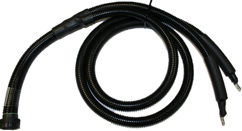
26 Appendix A - Wire Harness / Electrical Diagrams All wiring harness diagrams (including the main module shroud wiring harness and the power and ground wiring harness) that define connector pin outs and to/from locations to support in troubleshooting are located on the Modine FTP site. Instructions for downloading from the Modine FTP can be found in Section 4 Downloading Diagnostic Software. Appendix B - Common Service Parts The list below includes common service parts for E-fan Cooling Module shroud assemblies, including the E-fan, controller and wire harness connector service kits to avoid purchasing a complete new wire harness assembly. This list is not intended to include all service parts available for the entire cooling module. The end user should consult OEM for all available service parts including heat exchangers, full wire harness assemblies and steel channel assemblies. Modine Service Part # Gillig Service Part # Part # Description 3S Diagnostic Software (Cable / Software / Bulletin) 5S Electric Fan Gen II 5S TBD IO Controller Allison H40EP Hybrid 5S IO Controller Allison B400 / Allison D864.3 Transmission 5S IO Controller ZF Ecolife 6AP / Ecomat 4 Transmission 5S TBD IO Controller BAE Hybrid HDS100/200/300 3S Fan Connector Kit Harness Side (4100 RPM Fan) 3S Fan Connector Kit Fan Side (4100 RPM Fan) 3S Busbar Kit 12 Pin 3S Busbar Kit 4 Pin 3S CAN 3 Pin J1939 Connector Kit 3S pin Connector Kit Module Side 3S RS232 2x2 Connector Kit Wire Harness Side 3S RS232 2x2 Connector Kit Diagnostic Harness Side 3S Fuse & Holder Connector Kit Fan (30A) 3S Fuse & Holder Connector Kit Fan (5A) te: For Modine Service Part #, use S in the 2 nd digit for the part #. 25/26
27 Revision Log EFAN Troubleshooting Guide Latest Revision: 9/15/15 Revision Description Date CR A Released to production. 3/14/14 B Full redesign to become more useful. 7/3/ C Improve FTP instructions. Add barcode. 10/24/ D Replace FTP instructions with Modine.com. 1/27/ E Cover photo, Title, Section 2 Engine on, Section 4, Section 5, Deleted Appendix A 9/15/ /26
EVANS ELECTRONIC TEMPERATURE CONTROL TROUBLESHOOTING GUIDE for systems equipped with electric coolant valve and external PC board.
 EVANS ELECTRONIC TEMPERATURE CONTROL TROUBLESHOOTING GUIDE for systems equipped with electric coolant valve and external PC board. This Troubleshooting Guide covers the electric coolant valve and control
PUSH BUTTON START INSTALLATION MANUAL
 PUSH BUTTON START INSTALLATION MANUAL ALTHOUGH THIS PRODUCT HAS BEEN THOROUGHLY TESTED KPIERSON TECHNOLOGIES ASSUMES NO RESPONSIBILITY FOR ANY DAMAGE THAT MAY RESULT BY THE INSTALLATION OF THIS PRODUCT.
Signature and ISX CM870 Electronics
 Signature and ISX CM870 Electronics Cummins West Training Center System Description General Information The Signature and ISX CM870 engine control system is an electronically operated fuel control system
MTX-D Ethanol Content and Fuel Temperature Gauge User Manual
 MTX-D Ethanol Content and Fuel Temperature Gauge User Manual P/N 3912 kit does not include flex fuel sensor. The ECF-1 is compatible with GM P/Ns 13577429 and 13577379 1. Installation... 2 1.1 Gauge Mounting...
A/C-HEATER SYSTEM - AUTOMATIC
 A/C-HEATER SYSTEM - AUTOMATIC 1995 Volvo 850 1995-96 Auto. A/C-Heater Systems Volvo 850 * PLEASE READ THIS FIRST * WARNING: To avoid injury from accidental air bag deployment, read and carefully follow
Before installation it is important to know what parts you have and what the capabilities of these parts are.
 INSTALLATION GUIDE Before installation it is important to know what parts you have and what the capabilities of these parts are. The Recon XZT is the smallest and most powerful gauge of its kind. With
INSTRUMENT PANEL. 1995 Volvo 850 DESCRIPTION & OPERATION. 1995-96 ACCESSORIES & EQUIPMENT Volvo Instrument Panels
 INSTRUMENT PANEL 1995 Volvo 850 1995-96 ACCESSORIES & EQUIPMENT Volvo Instrument Panels 850 WARNING: When working around steering column and before performing repairs, disconnect and shield battery ground
INSTALLATION MANUAL 3RP / 5RP 4-BUTTON SERIES VEHICLE SECURITY SYSTEMS
 3RP / 5RP 4-BUTTON SERIES VEHICLE SECURITY SYSTEMS INSTALLATION MANUAL Before you begin the installation Read the INSTRUCTIONS! Always use a multi-meter when verifying vehicle wiring. Before mounting the
6. Diagnostics for A/C System Malfunction
 6. A: A/C OR SELF-DIAGNOSIS SYSTEMS DO NOT OPERATE TROUBLE SYMPTOM: Set temperature is not indicated on the display, switch LEDs are faulty or switches do not operate. Self-diagnosis system does not operate.
Thermo Top - Troubleshooting Tree
 Thermo Top - Troubleshooting Tree 07-15-2002 CAUTION Troubleshooting requires comprehensive knowledge about the structure and theory of operation of the Thermo Top heater. Troubleshooting and repairs may
Passive Anti -Theft System (PATS) Diagnostic Flowcharts. Issue: This bulletin provides diagnostic information for the Passive Anti-Theft System.
 Diagnostic Flowcharts. Issue: This bulletin provides diagnostic information for the Passive Anti-Theft System.") DTE 07/02 S419-12 SERVICE TECHNICL BULLETIN Passive nti -Theft System (PTS) Diagnostic Flowcharts MODEL VIN 2003 MY-ON S-TYPE M44998-ON Issue: This bulletin provides diagnostic information for the Passive
DTE 07/02 S419-12 SERVICE TECHNICL BULLETIN Passive nti -Theft System (PTS) Diagnostic Flowcharts MODEL VIN 2003 MY-ON S-TYPE M44998-ON Issue: This bulletin provides diagnostic information for the Passive
LMU-5000. Hardware and Installation Guide
 LMU-5000 Hardware and Installation Guide Plan The Installation Verify Power, Ground and Ignition. Be sure to check each source (power, ground and ignition) to ensure that the proper signaling exists. This
FAN-PWM-V3. Instructions
 FAN-PWM-V3 Instructions HOLDER AMP BOOKLET YELLOW RING CONNECTORS (2) INSTRUCTION INSTRUCTION BOOKLETBOOKLET ITEMS INCLUDED IN KIT INSTRUCTION ITEMS INCLUDED IN KIT ITEMS INCLUDED IN KIT INSTRUCTION BOOKLET
User Manual for CH-PFC76810
 AA Portable Power Corp www.batteryspace.com, Email: [email protected] User Manual for CH-PFC76810 1. Overview The CH-PFC76810 charger is suitable for charging lithium ion battery packs such as those
Troubleshooting Guide, Freedom and Fleet Power Inverter/Chargers
 Technical Note Freedom/Fleet Power 512-0084-01-01 Rev 1 Troubleshooting Guide, Freedom and Fleet Power Inverter/Chargers Overview This document is a guide for troubleshooting inverters, battery chargers,
PL-1, Pocket Logger 11-0135B
 PL-1, Pocket Logger 1 PL-1... 2 2 Wiring... 3 2.1.1 Single Innovate Device Relay Wiring Instructions... 3 3 Mounting... 4 4 Connecting the PL-1 to the MTS serial chain... 4 5 Recording... 5 6 LogWorks...
PRO PLM Installation Instructions
 PRO PLM Installation Instructions PROFESSIONAL INSTALLATION STRONGLY RECOMMENDED Installation Precautions: Roll down window to avoid locking keys in vehicle during installation Avoid mounting components
INSTRUCTION MANUAL FOR RECREATIONAL REFRIGERATOR/FREEZER MODEL
 INSTRUCTION MANUAL FOR RECREATIONAL REFRIGERATOR/FREEZER MODEL 15-LITER, 20-LITER, 35-LITER, 45-LITER, 60-LITER & 100-LITER SECTION 1 Basic Operation SECTION 2 Cleaning and Storing SECTION 3 Basic Trouble
Meritor WABCO Pneumatic Antilock Braking System (ABS) 42.22
 42.22") (ABS) 2.22 Troubleshooting WARNING Before testing a vehicle equipped with Automatic Traction Control (ATC) on a dynamometer, the ATC system must be disabled. See Subject 160 for instructions. Activation
(ABS) 2.22 Troubleshooting WARNING Before testing a vehicle equipped with Automatic Traction Control (ATC) on a dynamometer, the ATC system must be disabled. See Subject 160 for instructions. Activation
USB-Link 2 Installation and Setup Manual
 USB-Link 2 Installation and Setup Manual USB-Link 2 IDSC Holdings LLC retains all ownership rights to USB-Link 2 and its documentation. The USB-Link 2 source code is a confidential trade secret of IDSC
CAN BUS INTERFACE. Module Information
 Part no: CB-1 The CAN Bus interface is designed to provide a vehicle speed signal for vehicles using a CAN Bus system. It is programmed to automatically detect the vehicle type and it will give a frequency
LG Air Conditioning Multi F(DX) Fault Codes Sheet. Multi Split Units
 Fault Codes Sheet. Multi Split Units") Multi Split Units If there is a fault on any LG Multi unit, an Error mark is indicated on the display window of the indoor unit, wired-remote controller, and LED s of outdoor unit control board. A two
Multi Split Units If there is a fault on any LG Multi unit, an Error mark is indicated on the display window of the indoor unit, wired-remote controller, and LED s of outdoor unit control board. A two
ILISC515-A Shift Interlock (Manual Lift Door) 2015 Ford Transit, 3.7L and 3.5L
 2015 Ford Transit, 3.7L and 3.5L") An ISO 9001:2008 Registered Company ILISC515-A Shift Interlock (Manual Lift Door) 2015 Ford Transit, 3.7L and 3.5L Introduction The ILISC515-A is a microprocessor driven system for controlling wheelchair
An ISO 9001:2008 Registered Company ILISC515-A Shift Interlock (Manual Lift Door) 2015 Ford Transit, 3.7L and 3.5L Introduction The ILISC515-A is a microprocessor driven system for controlling wheelchair
SERVICE BULLETIN No.1103
 SERVICE BULLETIN No.1103 Circulate to listed addressees COACH MODEL BULLETIN TYPE MANUAL & SECTION PARTS BOOK REVISION : T 2100 and C2000 Series : Service Information : Maintenance Manual: Chapter 3 Drive
HPC Radiator Fan Control Module with Sensor PN: 102001
 Revised 25.07.15 www.hpcontrols.ca HPC Radiator Fan Control odule with Sensor PN: 102001 The HPC Radiator Fan Controller provides automatic control over one or more electric radiator fan(s). The module
Quickie Rhapsody Service Manual
 Quickie Rhapsody Service Manual 2006 Sunrise Medical Inc. 101976 Rev A Quickie Rhapsody Service Manual Contents Introduction... 0.1 VR2 Controller... 0.2 Plugs/Connectors... 0.3 Basic Tool List & Main
MAX ENERGY POWER PROGRAMMER PART #52001/52501 REFERENCE GUIDE AND INSTALLATION MANUAL ADDENDUM 2007-2010 JEEP WRANGLER WITH ENHANCED OFF-ROAD FEATURES
 MAX ENERGY POWER PROGRAMMER PART #52001/52501 REFERENCE GUIDE AND INSTALLATION MANUAL ADDENDUM 2007-2010 JEEP WRANGLER WITH ENHANCED OFF-ROAD FEATURES The following is a step by step guide for installing
INSTALLATION INSTRUCTIONS
 INSTALLATION INSTRUCTIONS Electric Vacuum Pump Kit 28146 Thank you for choosing STAINLESS STEEL BRAKES CORPORATION for your braking needs. Pleases take the time to read and carefully follow these instructions
TECHNICAL SERVICE DEPARTMENT Technical Service Bulletin 1-800-432-8373. 2 Inch PowerVent LED Indicator Explanations & Troubleshooting Table
 New Robertshaw control valve was introduced in May 2008 as a replacement part. See last page for troubleshooting this replacement part. All voltage inputs are 120V. All electrical connectors are Molex
R22. K Control. Indoor Unit. Nomenclature. Compatibility PL H 3 G K H B. Unit style Heat Pump Horse Power
 R22. K Control. Indoor Unit. Nomenclature. PL H 3 G K H B Compatibility Unit style Heat Pump Horse Power Control Boost Heaters R22. K Control. Outdoor Unit. Nomenclature. PU H 3 Y K A Compatibility Outdoor
Troubleshooting and Diagnostics
 Troubleshooting and Diagnostics The troubleshooting and diagnostics guide provides instructions to assist in tracking down the source of many basic controller installation problems. If there is a problem
Multi Function, User Configurable Remote Vehicle Security System with 4 Button Replaceable Membrane Remote Transmitter
 MODEL PRO-9744 INSTALLATION MANUAL Multi Function, User Configurable Remote Vehicle Security System with 4 Button Replaceable Membrane Remote Transmitter This System Allows The Transmitter Buttons To Be
Section 7. Evaporator thermistor. Under-and-over pressure safety switches. Connections to the ECU
 Automatic Temperature Control Diagnosis and Repair Diagnosis of Automatic A/C Systems The most common automatic A/C system malfunctions tend to be the result of basic air conditioning problems. These problems
ENERGY SMART TROUBLESHOOTING GUIDE TABLE OF CONTENTS:
 ENERGY SMART TROUBLESHOOTING GUIDE TABLE OF CONTENTS: COMPONENTS/BOARD LAYOUT... 2 HOT WATER... 3 1 FLASH (GREEN DIAGSTIC LIGHT)... 4 2 FLASHES (GREEN DIAGSTIC LIGHT)... 5 3 FLASHES (GREEN DIAGSTIC LIGHT)...
Air conditioning, electrical testing
 just a test. Air conditioning, electrical testing 01-253 Wire and component test using VAG1598 A test box Special tools and equipment VAG 1598 A test box and VAG 1598/11 adapter cable and VAG 1598/12 VAG1526
ABS Flash Code (Blink Code) Instructions
 Instructions") ABS Flash Code (Blink Code) Instructions Innovative Products of America Incorporated Tinker Street, Woodsttock, NY 8 Local: 8-6-00 Toll Free: 888-86-8 Fax: 8-6-600 www.ipatools.com [email protected] ABS
ABS Flash Code (Blink Code) Instructions Innovative Products of America Incorporated Tinker Street, Woodsttock, NY 8 Local: 8-6-00 Toll Free: 888-86-8 Fax: 8-6-600 www.ipatools.com [email protected] ABS
Manual for Fire Suppression & Methane Detection System
 Manual for Fire Suppression & Methane Detection System Fogmaker North America Post address: 150 Gordon Dr Exton, PA 19341 Delivery address: 150 Gordon Dr Exton, PA 19341 Tel: 610-265-3610 Fax: 610-265-8327
FG MOISTURE MONITOR Installation & Operation Manual
 FG MOISTURE MONITOR Installation & Operation Manual Issue 3.0 7/20/10 1 Contents SERVICE AND TECHNICAL SUPPORT... 2 INSTALLATION:... 3 MOISTURE SENSOR INSTALLATION:... 3 SENSOR CONNECTOR:... 5 MONITOR
Digi-Motor Installation Guide
 Digi-Motor Installation Guide Installation Video...located at marsdelivers.com Digi-Motor Installation Guide Digi-Motor For technical assistance with your Azure Digi-Motor, call the MARS technical support
TOYOTA ELECTRONIC TRANSMISSION CHECKS & DIAGNOSIS
 Checks and Adjustments The transmission requires regular maintenance intervals if it is to continue to operate without failure. As we discussed in previous sections, transmission fluid loses certain properties
Fuel Alert FA-KRS-P21. Mounting instruction
 Fuel Alert Mounting instruction 1- General Points : Alarm Mode and Measure Mode 2- Connections 3- Notice, warnings 4- Compatibility check up with the vehicle s level sensor 5- Wire connections with the
Left Hand Limit Switch. Housing. Left Hand. Connections. Motor Connector BROWN PURPLE GRAY BLACK DARK BLUE BLACK BROWN BROWN LIGHT BLUE.
 LIGHT BLUE GRAY PURPLE Circuit Breaker Intput Circuit Breaker Output #1 Relay Left Hand Limit Switch Housing Left Hand Motor Connector Right Hand Limit Switch on Radiator Support Right Hand Limit Switch
OWNER'S MANUAL Installation, Operation, and Maintenance Information
 OWNER'S MANUAL Installation, Operation, and Maintenance Information Back Pressure Monitor (BPM) for Diesel Particulate Filter Mufflers Manual No. P480922 Rev 1 This manual is property of the owner. Leave
Heater and Air Conditioner, Blend Air System, Troubleshooting 83.06
 A/C Performance Diagnosis Problem Warm Airflow When the Air Conditioner is On, A/C Not Working, or Poor A/C Performance (dash outlet temperature is too high) Problem Warm Airflow When the Air Conditioner
1R / 4-BUTTON SERIES
 Button 1 1R / 4-BUTTON SERIES VEHICLE SECURITY SYSTEM Standard Features: Two 4-Button Remote Transmitters Status indicator (LED) Valet / override switch Multi-tone siren Dual stage impact detector Remote
HID H4 BI-XENON FITTING GUIDE. Carefully read the following notes before starting work.
 HID H4 BI-XENON FITTING GUIDE Carefully read the following notes before starting work. WARNING! This HID kit should only be installed by someone competent in vehicle wiring and electrics. Incorrect fitment
G-100/200 Operation & Installation
 G-100/200 Operation & Installation 2 Contents 7 Installation 15 Getting Started 16 GPS Mode Setup 18 Wheel Sensor Mode Setup 20 Fuel Calibration 23 Basic Operation 24 Telemetery Screen 27 Entering a Distance
A4 Air Conditioning Control Circuit Troubleshooting Rev 7, 6/18/2009
 A4 Air Conditioning Control Circuit Troubleshooting Rev 7, 6/18/2009 ** This guide is for Manual Air Conditioning (as opposed to Climatronic A/C or Climatic A/C), with two 2-speed fans on Volkswagen A4's
FUEL-16, Troubleshooting Fuel Supply Problems
 FUEL-16, Troubleshooting Fuel Supply Problems Introduction This procedure is used to troubleshooting fuel supply problems including failure of the fuel pump to start during engine cranking. Fuel Pump Not
BODY ELECTRICAL TOYOTA ELECTRICAL WIRING DIAGRAM WORKBOOK. ASSIGNMENT Version 1.8 WORKSHEETS. http://www.autoshop101.com
 BODY ELECTRICAL ASSIGNMENT Version 1.8 WORKSHEETS TOYOTA ELECTRICAL WIRING DIAGRAM WORKBOOK http://www.autoshop101.com Developed by Kevin R. Sullivan All Rights Reserved TOYOTA Table of Contents Wiring
RECOMMENDED TOOLS PERSONAL & VEHICLE PROTECTION SAFETY GLASSES
 PART NUMBER: 250-9612 GENERAL APPLICABILITY THIS CRUISE WAS TESTED AND VERIFIED ON: FORD FOCUS SE & S MODELS (AT/MT) FORD TRANSIT ALL MODELS RECOMMENDED TOOLS PERSONAL & VEHICLE PROTECTION SAFETY GLASSES
K9 Heat Alarm Owners Manual HA-1520
 K9 Heat Alarm Owners Manual HA-1520 Your K9 Heat Alarm is a state of the art product designed and developed by ACEK9.COM a division of Radiotronics, Inc. It is a unique blend of positive features taken
Mobile Data Power Model: MDP-25
 Mobile Data Power Model: MDP-25 Topic Section Features... 2 Operational Features Summary... 2 Back-up Battery Power Internal Charger Voltage Spike Protection RF Noise Filtering Warning of Imminent Loss
How to read this guide
 How to read this guide The following shows the symbols used in this Quick start guide with descriptions and examples. Symbol Description Example P oint Reference Caution [ ] This symbol explains information
iloq P10S.10/20 Programming device User's Guide
 iloq P10S.10/20 Programming device User's Guide CONTENTS CONTENTS... 2 GENERAL... 3 USING THE PROGRAMMING DEVICE... 5 Starting the programming device... 5 Programming of locks... 5 Programming of keys...
Sierra Dual 24 Volt Brushless DC Motor Controller Product Specification
 Sierra Dual 24 Volt Brushless DC Motor Controller Product Specification Assembly 025A0215 600A0942 Rev. A May 14, 2012 025A0215 Brushless DC Motor Controller Page 1 Revision History ECN # Date Rev Description
ANTI-THEFT SYSTEM. 1995 Volvo 850 DESCRIPTION & OPERATION BASIC ALARM. 1995-96 ACCESSORIES & EQUIPMENT Volvo Anti-Theft Systems
 ANTI-THEFT SYSTEM 1995 Volvo 850 1995-96 ACCESSORIES & EQUIPMENT Volvo Anti-Theft Systems 850 DESCRIPTION & OPERATION WARNING: Deactivate air bag system before performing any service operation. For 1995
Installation/Operator Manual For use with WFCO ULTRA III Power Center Model WF-8712P and WF-8725P
 Installation/Operator Manual For use with WFCO ULTRA III Power Center Model WF-8712P and WF-8725P Distributed in the U.S.A. and Canada by CHENG USA, INC. Sales (574) 294-8997 Warranty Service (877) 294-8997
KEYLESS ENTRY UPGRADE SECURITY SYSTEM for 2004 TOYOTA HIGHLANDER
 KEYLESS ENTRY UPGRADE SECURITY SYSTEM for 2004 TOYOTA HIGHLANDER DEALER SERVICE AND INSTALLATION MANUAL KIT NO. 00016-30915 Contents PARTS LIST... 2 PARTS ILLUSTRATIONS... 2 VEHICLE PREPARATION... 3 INSTALLING
HVAC SYSTEM (AUTO A/C) (DIAGNOSTICS) AC
 (DIAGNOSTICS) AC") HVAC SYSTEM (AUTO A/C) (DIAGNOSTICS) AC Page. Basic Diagnostic Procedure.... General Description...3 3. Electrical Components Location...6 4. A/C Control Module I/O Signal...8 5. Self-diagnosis...0 6.
HVAC SYSTEM (AUTO A/C) (DIAGNOSTICS) AC Page. Basic Diagnostic Procedure.... General Description...3 3. Electrical Components Location...6 4. A/C Control Module I/O Signal...8 5. Self-diagnosis...0 6.
Mastertech Diagnostic Software Frequently Asked Questions
 Mastertech Diagnostic Software Frequently Asked Questions Version 1.8 02 February 2010 Table of Contents MDS USER INTERFACE - OVERVIEW... 2 HARDWARE AND O/S REQUIREMENTS... 2 HARDWARE AND O/S REQUIREMENTS...
The Child Reminder System Installation Manual
 The Child Reminder System Installation Manual Revised June, 2006 Detailed installation information can be found at www.childreminder.com. Get through your installation quickly and easily by calling 1-888-330-6786
USB-Link 2 Wi-Fi Edition Installation and Setup Manual
 USB-Link 2 Wi-Fi Edition Installation and Setup Manual USB-Link 2 Wi-Fi Edition Installation and Setup Manual IDSC Holdings LLC retains all ownership rights to USB-Link 2 and its documentation. The USB-Link
STIM202 Evaluation Kit
 Table of contents: 1 FEATURES... 2 2 GENERAL DESCRIPTIONS AND SYSTEM CONTENTS... 2 3 SYSTEM REQUIREMENTS... 2 4 GETTING STARTED... 3 4.1 INSTALLATION OF NI-SERIAL CABLE ASSEMBLY DRIVER... 3 4.2 INSTALLATION
MP-4000 Alarm List (Software version 2.4.3 or later)
") Service Bulletin SUBJECT: MP4000 Alarm s BULLETIN: C 100 DATE: June 19, 2013 ALARM LIST Where it is possible the alarm number is kept the same as for MP-3000. MP-3000 holds alarm number from 0 to 127.
Service Bulletin SUBJECT: MP4000 Alarm s BULLETIN: C 100 DATE: June 19, 2013 ALARM LIST Where it is possible the alarm number is kept the same as for MP-3000. MP-3000 holds alarm number from 0 to 127.
WAMLocal. Wireless Asset Monitoring - Local Food Safety Software. Software Installation and User Guide BA/WAM-L-F
 Wireless Asset Monitoring - Local Food Safety Software BA/WAM-L-F Software Installation and User Guide System Overview The BAPI Wireless Asset Monitoring Local (WAM Local) Software receives temperature
Service Guide 12/27/03 TESTING, SERVICE & REPAIR GUIDE (For SH Space Heating Models & RA Water Heating Models)
") TESTING, SERVICE & REPAIR GUIDE (For SH Space Heating Models & RA Water Heating Models) WARNING - HIGH VOLTAGE AC electrical circuits are connected to this heater. Do not attempt any service work on the
TESTING, SERVICE & REPAIR GUIDE (For SH Space Heating Models & RA Water Heating Models) WARNING - HIGH VOLTAGE AC electrical circuits are connected to this heater. Do not attempt any service work on the
Workshop Repair Manual
 Workshop Repair Manual N.T. 2863A All types Basic manual: M.R. 302 - M.R. 307 - M.R. 311 - M.R. 312 M.R. 291 - M.R. 293 77 11 196 407 OCTOBER 1997 Edition Anglaise "The repair methods given by the manufacturer
4-Channel Thermometer / Datalogger
 USER GUIDE 4-Channel Thermometer / Datalogger RTD and Thermocouple Inputs Model SDL200 Introduction Congratulations on your purchase of the Extech SDL200 Thermometer, an SD Logger Series meter. This meter
INSTALLATION GUIDE. www.security.soundstream.com FCC ID NOTICE
 AL.1 AUTO SECURITY SYSTEM INSTALLATION GUIDE www.security.soundstream.com FCC ID NOTICE This device complies with Part 15 of the FCC rules. Operation is subject to the following conditions: 1. This device
LS1024B / LS2024B/ LS3024B. Solar Charge Controller USER MANUAL
 EPSOLAR LS1024B / LS2024B/ LS3024B Solar Charge Controller USER MANUAL Thank you very much for selecting our product! This manual offers important information and suggestions with respect to installation,
SYSTEM 4C. C R H Electronics Design
 SYSTEM 4C C R H Electronics Design SYSTEM 4C All in one modular 4 axis CNC drive board By C R Harding Specifications Main PCB & Input PCB Available with up to 4 Axis X, Y, Z, A outputs. Independent 25
Networkfleet 3500 Product Line Installation Guide
 Networkfleet 3500 Product Line Installation Guide Light/Medium Duty (L3500) Heavy Duty (H3500) Universal (U3500) www.networkcar.com/fleet Customer Care: (866) 227-7323 [email protected] Table
User Manual. Air-conditioner Controller SB-DN-HVAC (MAC01.331) www.hdlautomation.com
 www.hdlautomation.com") Air-conditioner Controller SB-DN-HVAC (MAC01.331) www.hdlautomation.com Document updates: Version Data Description V1.0 2015.05.25 Finish new document HVAC Controller User Manual INDEX 1. Overview...1
Air-conditioner Controller SB-DN-HVAC (MAC01.331) www.hdlautomation.com Document updates: Version Data Description V1.0 2015.05.25 Finish new document HVAC Controller User Manual INDEX 1. Overview...1
Renewable Energy Monitor User Manual And Software Reference Guide. [email protected] (979) 703-1925
 703-1925") Renewable Energy Monitor User Manual And Software Reference Guide [email protected] (979) 703-1925 1 Introducing the Horizon Renewable Energy Monitor The Renewable Energy Monitor is an educational
Renewable Energy Monitor User Manual And Software Reference Guide [email protected] (979) 703-1925 1 Introducing the Horizon Renewable Energy Monitor The Renewable Energy Monitor is an educational
TOYOTA TECHNICAL. An example of a tire pressure monitor valve sub-assembly. This mounts to a drop area in the wheel.
 TOYOTA TIRE PRESSURE WARNING SYSTEM Toyota uses various tire pressure warning systems. Here, we ll discuss the system featured on the 2006 Land Cruiser. Combination meter warning reset switch warning reset
OWNER'S MANUAL. Model 20-1050CUL AC Power Inverter/Charger System OM/A96283 REV. A
 OWNER'S MANUAL Model 20-1050CUL AC Power Inverter/Charger System OM/A96283 REV. A Table of Contents Section 1 Introduction... 1 Section 2 Installing the 20-1050CUL... 4 Section 3 Installing the IFM1 Interface
INSTALLATION & SERVICE MANUAL. Display Panel
 INSTALLATION & SERVICE MANUAL Display Panel The PowerLine EMS TM is a specialized power distribution and energy management system intended to be used in recreational vehicles. The Control Module is housed
GENUINE PARTS INSTALLATION INSTRUCTIONS
 GENUINE PARTS INSTALLATION INSTRUCTIONS DESCRIPTION: Illuminated Kick Plate APPLICATION: Rogue (2011) PART NUMBER: 999G6 GX010 KIT CONTENTS: Item A B C G H QTY 1 1 1 D 1 E 1 F 3 15 6 Description Kick Plate,
Model 201 Wiegand Touchpad Reader Installation Guide
 Model 201 Wiegand Touchpad Reader Installation Guide P/N 460353001C 15AUG11 2011 UTC Fire & Security. All rights reserved. This document may not be copied in whole or in part or otherwise reproduced without
CDS TROUBLESHOOTING SECTION I. VACUUM. 1.0. Weak vacuum at wand. Gauge reads normal (10hg to 14hg)
") CDS TROUBLESHOOTING SECTION I. VACUUM 1.0. Weak vacuum at wand. Gauge reads normal (10hg to 14hg) 1.1. Clogged hoses or wand tube. Disconnect hoses and carefully check for an obstruction. 1.2. Excessive
CDS TROUBLESHOOTING SECTION I. VACUUM 1.0. Weak vacuum at wand. Gauge reads normal (10hg to 14hg) 1.1. Clogged hoses or wand tube. Disconnect hoses and carefully check for an obstruction. 1.2. Excessive
Companion Service Guide
 Companion Service Guide This Service Guide contains: Troubleshooting Replacement Instructions Contact Information Golden Technologies 401 Bridge Street Old Forge, PA 18518 Toll-free: 800-624-6374 Fax:
ABS/VDC WHEEL SPEED SENSOR DIAGNOSIS
 Classification: Reference: Date: BR10-007a NTB10-102a September 25, 2012 ABS/VDC WHEEL SPEED SENSOR DIAGNOSIS This bulletin has been amended to revise the Applied Vehicles and Service Information. Please
Fan Coil EC Motor Control
 Fan Coil EC Motor Control G3 PWM BARD The Enviro-Tec Generation 3 PWM (G3 PWM) board provides a pulse-width modulated (PWM) signal to the EC motor to control fan speed. The board is factory programmed
Model AM2. Installation Guide
 Model AM2 Installation Guide NOTE: This product is intended for installation by a professional installer only! Any attempt to install this product by any person other than a trained professional may result
Stop Alert Flasher with G-Force sensor
 Stop Alert Flasher with G-Force sensor Stop Alert module creates brake light flashing effect to catch attention of the drivers behind to avoid dangerous rear end collision. The flasher module is a state
ASWC Axxess Steering Wheel Control Interface Installation Manual
 IGNITION TERMINALS 6 2.5 ISO 1.5 M4 M5 M3 WIRE CUTTER INSTALLATION INSTRUCTIONS FOR PART ASWC ASWC Axxess Steering Wheel Control Interface Installation Manual KIT FEATURES One Interface does it all - No
HCS-3300/3302/3304 USB Remote Programmable Laboratory Grade Switching Mode Power Supply
 1. INTRODUCTION HCS-3300/3302/3304 USB Remote Programmable Laboratory Grade Switching Mode Power Supply User Manual This family of efficient, upgraded SMPS with small form factor, auto cross over CV CC,
INSTALLATION MANUAL VEHICLE SECURITY SYSTEM CE-SS200
 INSTALLATION MANUAL VEHICLE SECURITY SYSTEM CE-SS200 FUSION CULTURE TABLE OF CONTENTS There s no point doing something if no one notices. We ve always believed the way to make things happen is by getting
DiCE INSTALLATION INSTRUCTION
 DiCE INSTALLATION INSTRUCTION Volvo Cars of North America, LLC DiCE Installation Instructions 1(18) Contents 1 INTRODUCTION 3 1.1 SUPPORT 3 1.2 UNINSTALL BUILT-IN BLUETOOTH 4 1.3 INSTALL THE LATEST VIDA
ADDING and/or DELETING PIN NUMBERS (Plus other simple programming commands) in My DK-16 or DK-26 DIGITAL KEYPAD
 in My DK-16 or DK-26 DIGITAL KEYPAD") ADDING and/or DELETING PIN NUMBERS (Plus other simple programming commands) in My DK-16 or DK-26 DIGITAL KEYPAD A recurring call that we get here at Securitron Technical Support is from end users of our
ADDING and/or DELETING PIN NUMBERS (Plus other simple programming commands) in My DK-16 or DK-26 DIGITAL KEYPAD A recurring call that we get here at Securitron Technical Support is from end users of our
Quick Start Guide RIVA/Athena Sea-Doo ECU
 Quick Start Guide RIVA/Athena Sea-Doo ECU PART# - RS11891-ECU-DC APPLICATION(S): Sea-Doo 260/255/215hp icontrol Models RIVA/Athena ECU Manager Web Site: www.rivaathena.com NOTE: YOU MUST PERFORM PHYSICAL
User Guide Reflow Toaster Oven Controller
 User Guide Reflow Toaster Oven Controller Version 1.5-01/10/12 DROTEK Web shop: www.drotek.fr SOMMAIRE 1. Introduction... 3 2. Preparation of THE REFLOW CONTROLLER... 4 2.1. Power supply... 4 2.2. USB
PRODUCTIVITY THROUGH INNOVATION 600 CONTROL DIRECT DRIVE TECHNICAL/OPERATION MANUAL
 Rev. D PRODUCTIVITY THROUGH INNOVATION 600 CONTROL DIRECT DRIVE TECHNICAL/OPERATION MANUAL 10 BORIGHT AVENUE, KENILWORTH NEW JERSEY 07033 TELEPHONE: 800-524-0273 FAX: 908-686-9317 TABLE OF CONTENTS Page
Standard WIRED Installation Guide
 Standard WIRED Installation Guide Version 1.0.1 1 Installing the STANDARD WIRED DEVICE The installation of the STANDARD WIRED DEVICE and its antennas can have a major impact on the STANDARD WIRED DEVICE
MTX-D, Oil Temperature/Pressure Gauge
 MTX-D, Oil Temperature/Pressure Gauge 1 Mounting and Sensor Installation... 3 1.1 Mounting the Gauge... 3 1.2 Oil Temp Sensor... 3 1.3 Oil Pressure Sensor... 3 2 Wiring... 3 2.1 Main Gauge Wiring... 4
e-ask electronic Access Security Keyless-entry
 e-ask electronic Access Security Keyless-entry e-fob Keyless-entry entry System Full-Function Function Installation Manual FCC ID: TV2EFOB1 (UM20 ~ 22793-02) Table of Contents Introduction... 1 e-fob Operation
Installation and Operation Guide PD4600 Series Converter Replacement
 Installation and Operation Guide PD4600 Series Converter Replacement Extended warranties are available for purchase at www.progressivedyn.com Member Thank you for selecting Progressive Dynamics as your
WIRING HARNESS FOR AS635P4. BLUE PLUG RED, BLUE, BLACK, WHITE - Plug in dual stage sensor harness
 WIRING HARNESS FOR AS635P4 ANTENNA NOT USED 5 PIN WHITE PLUG 2 PIN WHITE PLUG GREEN - PARKING BRAKE INPUT (-) BLUE - NOT USED 3 PIN BLUE PLUG RED, BLUE, BLACK, WHITE - Plug in dual stage sensor harness
TECHNICAL BULLETIN 303-35. V8 XJ Series/XK8. Difficult Cold Start Normally Aspirated Engines ECM Flash Reprogramming Service Action S479 SERVICE
 SERVICE V8 XJ Series/XK8 DATE 11/99 Amended 04/01 TECHNICAL BULLETIN Difficult Cold Start Normally Aspirated Engines ECM Flash Reprogramming Service Action S479 Remove and destroy Bulletin 303-35, amended