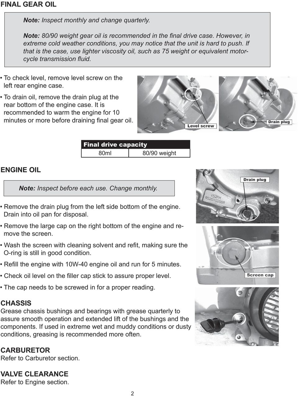
SERVICE MANUAL 150cc Engine
|
|
|
- Steven Watts
- 7 years ago
- Views:
Transcription
1 SERVICE MANUAL 150cc Engine

2

3 TABLE OF CONTENTS CHASSIS NUTS AND BOLTS 1 ENGINE 3 LUBRICATION SYSTEM 18 FUEL SUPPLY SYSTEM 22 TRANSMISSION COMPONENTS 27 ELECTRICAL STARTING SYSTEM 30 BELT DRIVE CVT MECHANISM 36 CLUTCH 40 REAR TRANSMISSION SYSTEM 45 ELECTRICAL SYSTEM 50 IGNITION SYSTEM 56

4

5 CHASSIS NUTS AND BOLTS Note:. Always pay attention to the unit s nuts and bolts. Some loosening after use is normal. Check to ensure that all nuts and bolts are tight. Torque Tightening Chart Bolt Conventional Marked Bolt 8.8 Marked Bolt Diameter N.m Kg.m Ib-ft N.m Kg.m Ib-ft 4 1 ~ ~ ~ ~ ~ ~ ~ ~ ~ ~ ~ ~ ~ ~ ~ ~ ~ ~ ~ ~ ~ ~ ~ ~ ~ ~ ~ ~ ~ ~ ~ ~ ~ ~ ~ ~ ~ ~ ~ ~ ~ ~ ~ ~ ~ ~ ~ ~ ~ ~ ~ ~ ~ ~ FUEL SWITCH (PETCOCK) Periodically clean the petcock externally with grease remover and water. Check for any leaks or seeping fuel. Replace the petcock if there are any leaks found. This vehicle has a manually operated fuel valve. There are three positions. ON position The normal operating position for the fuel valve lever is the ON position. In this position, fuel will r. RES position If the fuel level in the fuel tank becomes too low for the engine to operate with the fuel valve lever in the ON position, turn the lever to the RES position to use the reserve fuel supply, and refuel as soon as possible. OFF position The closing position for the fuel valve is the OFF position. When the vehicle is not in use, always make sure the petcock is in the OFF position.

6 unit before gear 2
7 ENGINE ENGINE COMPONENTS INSPECTION AND SERVICING ENGINE COMPONENTS AND CRANK CONNECTING ROD MECHANISM INSPECTION AND SERVICING ENGINE COMPONENTS: CYLINDER CYLINDER REMOVAL The removal can be done on the vehicle body. Remove cylinder head. Remove cylinder. Remove cylinder gasket, bolts Clean cylinder gasket and remove any debris. Caution! Do not damage the cylinder area. Make sure not to drop anything, including cylinder gasket material, into the crankcase. CYLINDER INNER WALL WEAR INSPECTION Use a bore diameter dial gauge to measure the degree of wear. The measure point is divided into three sectional planes in the axial direction: upper, middle and lower; measure every plane each time on the mutually perpendicular directions (X, Y), the measured least dimension is the cylinder bore; at the most upper position measured is the largest diameter, and the lowest position measured is the smallest diameter, their difference is the cylindricity of the cylinder. At the same cross section, measure the difference of diameter between two points mutually perpendicular; which is the circularity of the cylinder. In order to make the measuring point perpendicular with the bore axis of the cylinder, and to ensure the precision of the measurement, the bar of the gauge can be slightly swung in the direction of the gauge bar, and take the smallest reading number as the result. In the situation without a dial gauge, a feeler gauge can be used to make relativity measurement. put a new piston into the cylinder, and use the feeler gauge to measure the gap between the piston skirt and the cylinder wall. T hen gure out the abrasion loss of the cylinder. If the circularity of the cylinder exceeds the limit, then a cylinder reboring machine should be used to rebore the cylinder, and enlarge its diameter by 0.5mm or 1.00mm, then t the piston and piston ring which size are also enlarged. If the wear is too severe and cannot be reworked, then a new cylinder should be installed. Cylinder bore Cylindricity Circularity 57.4mm 0.05mm 0.05mm 3
, the measured")
8 4
9 5

10 6
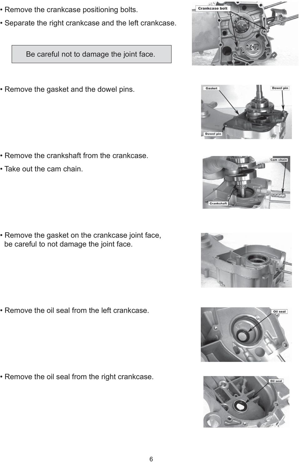
11 CRANKSHAFT AND CRANKCASE INSPECTION Replace the whole set of the crankshaft if serious wear is found while inspecting. Measure the axial trend clearance of the big end of the connecting rod. When measuring, put the large end of the connecting rod close to the crank, and insert the feeler gauge between the other side and the crank, for the correct end play. Service Limit 0.55mm Measure the radial trend (X,Y) clearance of the big end of the connecting rod. Service Limit 0.05mm Measure the main shaft journal jump of the crankshaft. If this measurement is too great, it will cause the engine to shake abnormally, shortening the life of the engine It must be examined carefully when inspecting. Service Limit 0.10mm(A=90) 0.10mm(B=105) Examine if there is any loose, or unusual sound when the crank journal bearing turns. If there is, the whole set should be changed. After cleaning the crankcase, inspect if there is any damage. Inspect whether the joint face of the crankcase is smooth and clean. While reassembling, notice if it will affect the sealing performance between the left and right crankcase. refinish it. If damage is too severe, replace the cover. Because the right and left crankcase axle hole must be concentric, they should be replaced at the same time. CRANKSHAFT AND CRANKCASE INSTALLATION Mount the crankcase oil seal. Put the cam chain into the left crankcase. Put the crankshaft into the left crankcase. Pay attention to avoid damaging the oil seal with the cam chain. 7
 0.")
12 .. 8

13 enable the engine to run properly,. W W 9

14 the causes. I too much play, 0

15 CAMSHAFT INSTALLATION ROCKER ARM AND ROCKSHAFT ROCKER ARM AND ROCKSHAFT REMOVAL ROCKER ARM AND ROCKSHAFT INSPECTION 11

16 Measure the inner diameter of the rocker arm. Service Limit Measure the outer diameter of the rockshaft. Service Limit 10.04mm 9.96mm ROCKER ARM AND ROCKSHAFT INSTALLATION Read the EX mark on the camshaft holder, then mount the exhaust port rocker arm to the rockshaft. Mount the inlet port rocker arm to the rockshaft. Apply some oil to the rockshaft before mounting. CAM CHAIN TENSIONER The chain tensioner must be in good working condition for proper chain tension. 1. Cam chain 2. Cam chain tensioner 3. Cam chain tensioner lifter. 4. Gasket 5. Cam chain tensioner pivot 6. Cam chain guide 7. Bolt 8. Nut 9. O-ring 10. O-ring The operational principle of the tensioner is as shown in the picture. As for the adjustment of the cam chain tensioner, clockwise tightens, and counterclockwise loosens. 12

17 VALVE AND VALVE SPRING VALVE AND VALVE SPRING REMOVAL Remove cylinder head. Remove valve cotter pin and compressor. Remove upper spring race. Remove valve spring. Remove lower spring race. Remove valve stem oil seal. Remove valve. The removed parts should be placed in order to avoid confusion. It s better to place the intake valve parts and exhaust valve parts separately. VALVE AND VALVE SPRING INSPECTION Inspect the valve for bending or burning. Inspect for smooth action between the valve and the valve guide. Measure the outer diameter of the valve stem. Service Limit 4.94mm Measure the free length of the inner and outer valve spring. Valve Inlet valve Exhaust valve Inner spring 31.2mm 31.2mm Outer spring 34.1mm 34.1mm VALVE AND VALVE SPRING INSTALLATION Mount the spring retainer, valve guide oil seal. It is recommended to replace the valve guide oil seal with a new one. After applying oil on the valve stem, mount it into the valve guide. Mount the inner and outer valve springs. Mount the valve locker with a spring compressor. When mounting, the twisting direction of the inner and outer springs must be opposite. Tap on the valve gently two or three times with a rubber hammer to make the valve and the valve lock connect well. Do not damage the valve. 13

18 VALVE GUIDE Carbon accumulation on the valve guide will make the valve move roughly, causing the valve to not open or close properly. Valve guide abrasion is one of the causes of white smoke from the exhaust pipe. TO CLEAN CARBON ACCUMULATION OFF THE VALVE GUIDE Remove the valve and springs etc. Clean the carbon accumulation with a valve guide reamer. Generally, only turn right when using the reamer, and do not push in or out directly with the reamer. VALVE GUIDE INNER DIAMETER MEASUREMENT Service Limit 5.03mm Calculate the clearance between the valve stem and the valve guide (the inner diameter of the guide subtracted by the outer diameter of the valve stem). Valve Inlet valve Exhaust valve Service Limit 0.08mm 0.10mm When the abrasion of the valve guide exceeds the service limit, it should be replaced; after replacing a new valve guide, the valve retainer must be adjusted. VALVE GUIDE REPLACEMENT Heat the cylinder head to 212 ~ 302 F (100 ~ 150 C) The cylinder head must be wholly and quickly heated y, or it will cause the cylinder head to distort. The temperature is very high, two technicians are recommended. Tap the valve guide out with a valve guide remover or similar tool. Do not damage the cylinder joint face 14

19 After tapping the valve guide, you need to trim it with a reamer. When using the reamer, cutting oil must be used. The reamer can only be turned right; do not push in or out directly. Clean the cylinder head, and remove the scraps generated while ramming. VALVE SEAT The relative position between the valve seat and the working surface of the valve is very important for the valve to seal properly. VALVE SEAT WIDTH MEASUREMENT Clean the carbon accumulation in the combustion chamber. Measure the width of the valve seat with a vernier caliper. Standard Service Limit mm 1.8mm When abrasion causes the valve seat width to be uneven, too wide or too narrow, it will result in poor contact between the valve and the valve seat, and not seal tight. At this time it must be reamed with a customized valve seat milling cutter. The valve seat milling cutter is the customized trimming tool for the valve seat, and it has three cutting angles: 32, 45, and 60. While trimming, press the valve seat milling cutter to make rotary motion with 40 ~ 50 N force. Some oil must be applied on the valve seat milling cutter, to eliminate scraping when trimming. VALVE SEAT FINISHING Ream out the defects on the working surface with a 45 coarse tooth milling cutter. Do not ream too much. 15

20 . Place ; 16
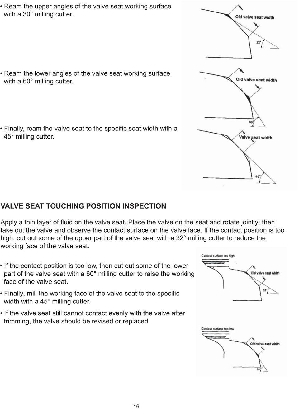
21 ve. U ing, area Follow the same method as for lace. Turn. If the lines are all broken, the level of air satisfactory M 17
22 LUBRICATION SYSTEM INSPECTION AND SERVICING GENERAL INTRODUCTION The picture shows the functional diagram of the lubrication system. After the lubrication oil crosses, it is pumped by the rotator oil pump. Some of the oil goes into the big end of the connecting rod and splashes on the cylinder wall and the small end of the connecting rod; the rest goes through some oil passages, such as the shaft neck of the camshaft, and splashes on the cam rockshaft and cam chain. The lubrication oil that falls back into the oil groove can be recirculated. 18
23 . allow. Replace if damaged. and tighten. appropriate kage. Stop the engine and inspect for proper oil level.. Inspect and maintain it. If, replace it as a unit., followed by removing 19
24 followed by removing followed by ing e After removing 0
25 1
26 Mount the right crankcase cover positioning bolt. Mount the trigger winding and the stator coil. Tighten the right crankcase cover positioning bolt. The bolt should be gradually diagonally tightened in two to three steps. spect for any oil leaks. FUEL SUPPLY SYSTEM INSPECTION AND SERVICING CV CARBURETOR The CV carburetor is a constant vacuum carburetor. The picture shows the structure of the CV carburetor. 1. Gasket set 2. Float valve set 3. Needle jet set 4. Float set 5. Float chamber set 6. Screw set A 7. Screw set B 8. Valve plate set 9. Starter valve set 10. Air cut valve set 11. Compression coil spring 12. Screw 13. Carburetor assy. 14. Top comp. 15. Vacuum piston comp. 16. Needle jet holder 17. Plate clip 18. Holder cap 19. Tube A 20. Tube B 21. Screw 22. Screw 23. Washer screw 24. Washer screw 25. Washer screw 26. Clip 27. Clip 28. Tube 29. Main jet 30. Slow jet
27 CARBURETOR IDLING ADJUSTMENT AIR ADJUSTING SCREW ADJUSTMENT Step one: Turn on the air adjusting screw in the turn out by the prescribed number of turns. Turn out number of turns 2 3/4 2 1/4 Step two: Adjust the throttle by adjusting the screw to the prescribed idle rpm. Step three: Left and right, adjust the air adjusting screw slightly to nd the highest position of the rpm. Increase throttle quickly and gently (the rpm is from low to high), and return throttle immediately, then observe 10 to 15 minutes, to observe if the idle remains the same. VACUUM CHAMBER The picture shows the structure of the vacuum chamber of the CV carburetor. VACUUM CHAMBER REMOVAL Remove the body cover. Remove the automatic choke lead wire. Loosen the fuel drain bolt, and drain the fuel in the oat chamber. Remove the fuel line and the vacuum pipe. Loosen the throttle cable adjusting nut and positioning nut; remove the throttle cable. Loosen the carburetor air inlet vent clip and the inlet manifold clip; remove the carburetor. Remove the vacuum cover bolt, and remove the vacuum cover. Notice: move slowly to prevent the spring from ejecting. Take out the spring, the vacuum membrane and the plunger. Press down the holding clamp of the needle valve top, and turn left to take out the clamp. Take out the spring and needle valve. Do not damage the vacuum membrane. Inspect the needle valve for wear. Inspect the vacuum membrane for damage. Inspect the plunger for damage. 23
28 Insert the spring ; vacuum u for ; ; ; 24
29 Before removing rst tighten the two screws gently, counting the number of turns Remove screws. Do not use excessive force to avoid damaging the air adjusting screw head surface. Remove the main fuel injection nozzle and fuel injection needle seat. FLOAT CHAMBER INSTALLATION oat valve seat for wear. If there is wear, it should be replaced. Clear every fuel line and air line on the carburetor body with compressed air. FLOAT CHAMBER INSTALLATION Install the main fuel injection nozzle and fuel injection needle seat. Install the air adjusting screw and choke adjusting screw, and turn them to the proper position according to the noted number of turns while removing. T w. FUEL LEVEL INSPECTION Measure the fuel level height. Fuel level height 18.5mm oat valve for excess wear. oat is normal. CARBURETOR INSTALLATION oat valve for excess wear. oat is normal. CARBURETOR INSTALLATION Reverse the removal procedure for installation. After installing, confirm that all carburetor linkage and cables are in correct position. Verify that carburetor is in idle position. 25
30 AIR CUT VALVE (ACV) The air cut valve can avoid some abnormalities when the throttle closes too quickly. The structure of the air cut valve is shown in the picture. AIR CUT VALVE REMOVAL Remove the air inlet manifold of the cut valve. Remove the bolt. R emove the vacuum membrane cover, the spring, and the vacuum membrane. AIR CUT VALVE INSTALLATION Mount the vacuum membrane on the carburetor. Mount the spring, the vacuum membrane cover, and the lock bolt. The bottom side of the vacuum membrane should be aligned with the carburetor. The top side should be aligned with the vacuum membrane. AIR CHECK VALVE The air check valve starts working under 31mph (50 km/h), and opens the second air inlet to reduce CO 2 displacement. AIR CHECK VALVE INSTALLATION Reverse the procedure for removal When installing, make sure all the connecting pipes are connected properly, and that they are not squeezed, bent, or clogged up. 26
31 TRANSMISSION COMPONENTS STARTING MECHANISM INSPECTION AND SERVICING The starting mechanism can be divided into two types: kick starting and electric starting. KICK RETURN STARTING MECHANISM SPIRAL SPLINE TRANSFERRING STYLE STARTING MECHANISM The picture shows the structure of the spiral spline transferring style starting mechanism Kick starter spring stopping plate 2. Drive face 14. Bush 3. Drive face boss 15. Spindle bush 4. Movable drive face comp. 16. Kick starter spring 5. Weight roller set 17. Special pin 6. Ramp plate 18. Washer 7. Slide piece 19. Washer 8. Starting driver pulley 20. Washer 9. Starter gear friction spring 21. Nut 10. Starter idle gear comp. 22. Bolt 11. Starter idle shaft 23. Roller 12. Starter idle spring 24. Face drive collar 13. Kick starter spindle comp. 25. Clip SPIRAL SPLINE TRANSFERRING STYLE STARTING MECHANISM REMOVAL Remove the left crankcase cover. Remove the crankcase gasket and dowel pins. Remove the movable driving plate (the whole set). Remove the starting spindle washer. 27
32 set starting spindle for abrasion or other damage. idle shaft for abrasion or other damage. spindle bushing and the starting idle shaft hole for abrasion or other damage 28
33 SPIRAL SPLINE TRANSFERRING STYLE STARTING MECHANISM INSTALLATION Install according to the pictures. Assemble the starting idle shaft set. Before assembling, apply a little grease on the bore of the idle shaft. Assemble the starting spindle, the return spring and the spring holding pin. A little grease should be applied on the starting spindle where it is under stress. Align the idle shaft holding pin with the groove of the crankcase then insert. Before installing, apply a little grease on the groove of the rotary retaining spring on the idle shaft. The rotary retaining spring should be aligned with Align the scribing mark of the starting spindle with the punching mark of the idle shaft then mount the starting spindle. Hook on the two ends of the return spring. Install the return spring stopping plate. Install the crankcase dowel pin and gasket. Install the driven belt and the driving plate. Install the left crankcase cover and lock tightly. Install the starting pedal. 29
34 ELECTRICAL STARTING SYSTEM STARTER MOTOR The starter motor is actually a direct current (DC) motor, and its structure is shown in the picture. 1. Outer Cover, Motor 7. O-ring 2. Rotor, Motor 8. O-ring 3. Base, Carbon Brush 9. Bolt 4. Plate, Positive Electrode 10. Spring Washer 5. Carbon Brush, Positive Electrode 11. Washer 6. Carbon Brush, Negative Electrode 12. O-ring 13. Screw STARTER MOTOR REMOVAL ff the main switch, and disconnect the battery connecting wire. Then press the starting button; at this time the starter motor should not run. Do this to insure safety. Remove the starter motor lead wire clamp. Remove the starter motor holding bolt, and remove the starter motor. Roll up the rubber wate-resistance cover, and remove the starter motor joint. Remove the motor case bolt, the carbon brush seat, and the motor case, etc. 30
35 Do the armature surface, nor on the immediate right far-. I. I t. I ; ; 1
36 STARTER MOTOR INSTALLATION Apply some oil on the dust seal. Install the carbon brush on the carbon brush base. Apply a little oil on the moving part of the armature ends. Put the carbon brush into the bracket, and then install the carbon brush base. Do not damage the contact area of the carbon brush and the armature. When installing, do not damage the lip of the dust seal. Mount the new O-ring on the carbon brush base. Install armature into starter motor case, making sure not to damage the carbon brushes. Tighten motor case bolts. Make sure the starter motor case is free of metal particles because it is magnetic. rst connect the lead wires and check that the motor is running normally. Apply oil on the O-ring, and install the starter motor. Tighten holding bolts. 32
37 REDUCTION MECHANISM The picture shows the structure of the reduction mechanism. 1. Starter reduction gear 2. Starter reduction gear shaft 3. Starting clutch gear comp. 4. Starting clutch outer comp. 5. Flange starting clutch 6. Starting clutch roller spring 7. Spring holder 8. Starter motor 9. Starter motor lead wire 10. Clamp 11. Clamp 12. Bolt 13. Nut 14. Washer 15. Dowel pin 16. Key woodruff 17. Roller 18. Needle bearing 19. O-ring 20. Screw 21. Bolt REDUCTION GEAR INSPECTION Remove the starting clutch. Remove the reduction gear to inspect its wearing degree. Measure the inner diameter of the reduction gear shaft. It should be replaced when the diameter is more than 10.05mm. Measure the outer diameter of the reduction gear shaft. It should be replaced when the diameter is less than 9.94mm. 33
38 ENGAGING MECHANISM STARTING CLUTCH REMOVAL Remove the right crankcase cover. Remove the left crankcase cover. Hold the drive face with the universal set wrench. Remove the starting clutch xing nut. handed rotation. Remove the starting clutch (the whole set). STARTING CLUTCH INSPECTION. The driving gear should smoothly turn clockwise, and should not move counterclockwise. for abrasion or other damage replaced if the surface is damaged. Measure the inner diameter of the driving gear placed when the diameter is more than 32.06mm. there is any damage. between the outer clutch component r for abrasion or other damage. Inspect the roller for injury. Inspect the spring for distortion. Measure the inner diameter of the replaced when the diameter is more than 27.94mm. 34
39 ; ; t ; While h ing. P If clicking sound is not heard, for conductivity the conductivity of the start button it is, then 35
40 and s. A Conversely, the speed decreases when the diameter of the driving belt pulley changes from big to small, and the diameter of the driven belt pulley changes proportionally from small to big. 36
41 37
42 While holding remove the for 38
43 ' sur 39
44 for for replace it and the 0
45 Remove the clutch friction plate. Remove the whole clutch/driven plate set. While compressing the driven pulley spring with the clutch spring compressor, remove the nut on the shaft. Disassemble the clutch with the driven pulley. Remove the circlip, and remove the connecting piece. Remove the clutch centrifugal weight set and the spring. CLUTCH INSTALLATION Mount the clutch damper rubber onto the drive plate pin. Mount the new clutch weight set and spring on the drive plate. Install the connecting piece, the circlip, and the bottom plate. Finally reverse the removal procedure for installation. To avoid damaging the spring when assembling the clutch and the driven plate, you must use a clutch spring compressor. The driven pulley must be free of grease. 41
46 for for for wear 2
47 3
48 and for cracking and wear 44
49 for oil leakage. T Always refill with the specified oil 45
50 Supply the oil with the prescribed speci cation and oil level. Mount the level bolt. After replacing the oil, inspect for any oil leaks. TRANSMISSION CASE TRANSMISSION CASE REMOVAL Remove the driven belt pulley. Drain out the oil in the transmission case. Remove the drive sprocket. Remove the bolt, and remove the transmission case cover. Remove the gasket and the dowel pin. r sub shaft/sub shaft gear. TRANSMISSION CASE GEAR INSPECTION Check the sub shaft/sub shaft gear for wear and other damage. other damage. and the nal gear shaft for wear and 46
51 47
52 48
53 and 49
54 Electrical System CHARGING SYSTEM INSPECTION AND SERVICING ELECTRIC LEAKAGE TESTING Turn the main switch to the OFF position. Disconnect the negative ground wire from the battery. Connect the positive end of the ammeter with the negative end of the battery. Connect the negative end of the ammeter with the ground wire. Test the electric leakage. In general, the number should be less than 1 m A; if it is unusual, check for is a short circuit of the main switch and the main wiring. CHARGING STATUS INSPECTION Install the fully charged battery. Connect the voltmeter between the binding posts of the battery. Remove the fuse, and connect the ammeter with two ends of the fuse. Connect the tachometer to the engine (it s not needed when there is rpm indicator on the vehicle). Start the engine, and accelerate slowly easure the charging voltage and current. Charging voltage (V) 13.5 ~ 15.5 Charging current (A) 0.5 *Measuring condition: 5000 r/min If the voltage is not in the range of the above-speci ed value, please inspect the voltage regulator. 50
55 BATTERY The battery is an important component of the electric system. The battery used on the vehicle is a maintenance-free battery. For long periods of storage, the battery will discharge. It should be charged every 3 months. After 2 ~3 years of regular usage, the capacity of the battery will lessen and will need changing. Replace with the same type of battery. BATTERY REMOVAL Shut down the main switch to make sure no electric current goes through the vehicle. Disconnect the negative battery lead wire rst. Disconnect the positive battery. The disconnecting order cannot be reversed. When disconnecting the positive cable, do not touch the body of the vehicle with the removal tool, or it will short circuit and ignite gas that will damage the battery. BATTERY INSTALLATION Connect the positive cable rst, then connect the negative cable. BATTERY OPEN-CIRCUIT VOLTAGE INSPECTION Disconnect the cable on the battery terminals. Disconnect the negative pole rst, then the positive pole. Measure the voltage between the two poles of the battery. Full charging 13.1V Under charging 12.3V 51
56 BATTERY CHARGING Lift the battery out of the vehicle. Connect the positive pole of the charger with the positive pole of the battery. Connect the negative pole of the charger with the negative pole of the battery. Charge the battery for the charging time marked on the battery. Unless it is urgent, do not use fast charging. There should be no smoking or open re near the battery when charging. At the beginning or the end of charging, turn off the Measure the voltage 30 minutes after charging is nished. It should reach the speci ed value, or recharging is needed. Charging Current Normal 0.7 A Fast 3.0 A Charging Time Normal 5-10 hours Fast 30 minutes Charging Result PRIMARY COIL The picture shows the structure of a common generator. 1. Cooling Fan Generator assembly 6. Bolt 3. Flywheel comp. 7. Nut 4. Stator comp. 8. Bolt 5. Washer 9. Bolt 52
57 While h ing 3
58 ed Perform 54
59 . If 55
60 A more than the timing should be adjusted.. If the contacts are bad, etc., determine. I 56
61 . T highest s. I and the problem and the problem 57
62 TRIGGER WINDING Remove the connector of the trigger winding wire. Measure the resistance value between the trigger winding (green/red wire) and the body ground wire. Standard Value When the actual value is more than the standard value, it should be replaced. CDI COMPONENT component inspection is also divided into two steps: First inspect every wiring, winding or REMOVE THE CDI COMPONENT. the trigger winding, and the ignition coil. When the main switch is in OFF position, it should be conducted. The resistance value of every coil should be the standard value.. CDI COMPONENT SW (B/W) EXT (B/R) SW (B/W) EXT (B/R) 0.5 ~ ~ ~ ~ ~ ~ 50 1 ~ 10 W - ellow Please carefully read the instrument speci ferent positions (OFF, P, EXT 58
63 IGNITION COIL IGNITION COIL REMOVAL Remove the spark plug cap. Remove the primary ignition coil wire. Remove the ignition coil-positioning bolt, and remove the ignition coil. IGNITION COIL INSTALLATION Reverse the removal procedure for installation. When installing, connect the black/yellow wire of the primary ignition coil with the black/yellow connector of CDI, and the green wire with the green connector of the CDI. PRIMARY IGNITION COIL INSPECTION Standard Value SECONDARY IGNITION COIL INSPECTION Install the spark plug cap, and measure the resistance value of the secondary ignition coil. Standard Value If the resistance value is in the standard range, it is good; however Remove the spark plug cap, and measure the resistance value of the secondary ignition coil. Standard Value If the resistance value is in the standard range, indicates it is good; however bad. The ignition coil also can be inspected and measured with the ignition testing instrument. Please operate properly according to the instructions. Turn the switch of the testing instrument to the ON position. Observe the spark and inspect the spark situation of the ignition coil. If it is a normal consistent spark, it is good; if y, it is not good. SPARK PLUG Clean the carbon around the spark plug to prevent it from dropping into the cylinder. Remove the spark plug. 59
64 When installing, connect the black/yellow wire of the primary ignition coil with the black/yellow connector of CDI, and the green wire with the green connector of CDI. th and carbon accumulation on the spark plug with a steel brush or a blade. Inspect the spark plug gap in general it should be about 0.6 ~ 0.7mm. When the carbon accumulation and wear of the spark plug are too severe, replace the spark plug. Replace with the spark plug of the same speci cation. 60
65 INDEX AIR ADJUSTING SCREW ADJUSTMENT 23 AIR CHECK VALVE 26 AIR CHECK VALVE INSTALLATION 26 AIR CUT VALVE (ACV) 26 AIR CUT VALVE INSTALLATION 26 AIR CUT VALVE REMOVAL 26 ARMATURE INSPECTION 31 AUTOMATIC SIDE STARTER INSPECTION 24 BATTERY 51 BATTERY CHARGING 52 BATTERY INSTALLATION 51 BATTERY OPEN-CIRCUIT VOLTAGE INSPECTION 51 BATTERY REMOVAL 51 BEARING ON THE LEFT CRANKCASE BODY REPLACEMENT 48 BEARING ON THE TRANSMISSION CASE COVER REPLACEMENT 47 BELT DRIVEN CVT MECHANISM INSPECTION AND SERVICING 36 CAM CHAIN TENSIONER 12 CAMSHAFT 10 CAMSHAFT INSPECTION 10 CAMSHAFT INSTALLATIION 11 CAMSHAFT REMOVAL 10 CAPACITIES 31 CARBURETOR 2 CARBURETOR IDLING ADJUSTMENT 23 CARBURETOR INSTALLATION 25 CDI COMPONENT 58 CDI COMPONENT 58 CHAIN ADJUSTRMENT 65 CHARGING STATUS INSPECTION 50 CHARGING SYSTEM INSPECTION 50 CHARGING SYSTEM INSPECTION AND SERVICING 50 CHASSIS 2 CHASSIS NUTS AND BOLTS 1 CLUTCH 46 61
66 CLUTCH DISASSEMBLING 40 CLUTCH INSPECTION 40 CLUTCH INSTALLATION 41 CLUTCH REMOVAL 40 CONNECTING ROD END INSPECTION 4 CONTROLING MECHANISM 36 CRANK CONNECTING ROD MECHANISM 4 CRANK CONNECTING ROD SET 5 CRANKCASE AND CRANKSHAFT REMOVAL 6 CRANKSHAFT AND CRANKCASE INSPECTION 7 CRANKSHAFT AND CRANKCASE INSTALLATIION 7 CV CARBURETOR 22 CYLINDER 3 CYLINDER INNER WAL WEAR INSPECTION 3 CYLINDER REMOVAL 3 DRIVE BELT PULLEY 38 DRIVE BELT PULLEY INSPECTION 38 DRIVE BELT PULLEY INSTALLATION 39 DRIVE BELT PULLEY REMOVAL 38 DRIVEN BELT PULLEY 42 DRIVEN BELT PULLEY INSPECTION 42 DRIVEN BELT PULLEY INSTALLATION 44 DRIVEN BELT PULLEY REMOVAL 42 DRIVEN PLATE BEARING REPLACEMENT 43 ELECTRIC LEAKGAE TESTING 50 ELECTRIC SYSTEM 50 ELECTRICAL STARTING MECHANISM 30 ENGAGING MECHANISM 33 ENGINE 6 ENGINE COMPONENTS 6 ENGINE COMPONENTS AND CRANK CONNECTING ROD 6 ENGINE COMPONENTS INSPECTION AND SERVICING 6 ENGINE OIL 2 FINAL GEAR OIL 2 FLOAT CHAMBER 24 FLOAT CHAMBER INSPECTION 25 FLOAT CHAMBER INSTALLATION 25 FLOAT CHAMBER REMOVAL 24 FOAM FILTER MAINTENANCE 1 62
67 FUEL LEVEL INSPECTION 25 FUEL SUPPLY SYSTEM INSPECTION AND SERVICING 22 FUEL SWITCH (PETCOCK) 1 GENERAL INTRODUCTION 18 GENERAL INTRODUCTION 36 GENERATOR INSTALLATION 54 GENERATOR REMOVAL 53 GENERATOR REMOVAL AND INSPECTION 53 IGNITION CHARGING COIL 57 IGNITION COIL 59 IGNITION COIL INSTALLATION 59 IGNITION COIL REMOVAL 59 IGNITION SYSTEM INSPECTION 56 IGNITION SYSTEM INSPECTION AND SERVICING 56 IGNITION TIME INSPECTION 56 KICK RETURN STARTING MECHANISM 27 LUBRICATION SYSTEM INSPECTION AND SERVICING 18 MAIN WIRING SUB ELECTRIC CIRCUIT CONDITION INSPECTION 54 MECHANISM INSPECTION 28 MECHANISM INSPECTION AND SERVICING 3 OIL PUMP ASSEMBLING 21 OIL PUMP INSPECTION 20 OIL PUMP INSTALLATION 21 OIL PUMP REMOVAL 19 OIL REPLACEMENT 19 OIL SYSTEM INSPECTION AND REPLACEMENT 19 OIL SYSTEM INSPECTION AND SERVICEING 50 PISTON PIN INSPECTION AND SERVICING 4 PISTON RINGS INSPECTION AND SERVICING 4 PISTON RINGS SET UP 5 63
68 PISTON SET 4 PISTON SET INSTALLATION 5 PRIMARY COIL 52 PRIMARY COIL INSPECTION 53 PRIMARY IGNITION COIL INSPECTION 59 REAR TRANSMISSION MECHANISM INSPECTION AND SERVICING 45 REDUCTION GEAR INSPECTION 33 REDUCTION MECHANISM 33 REGULATE RECTIFIER 54 REGULATE RECTIFIER INSPECTION 55 REMOVE THE CDI COMPONENT. 58 RESISTOR 55 RESISTOR RESISTANCE VALUE MEASUREMENT 55 ROCKER ARM AND ROCKSHAFT 11 ROCKER ARM AND ROCKSHAFT INSPECTION 11 ROCKER ARM AND ROCKSHAFT INSTALLATION 11 ROCKER ARM AND ROCKSHAFT REMOVAL 11 ROTARY OIL PUMP 19 SECONDARY IGNITION COIL INSPECTION 59 SPARK PLUG 59 SPIRAL SPINE TRANSFERRING STYLE STARING MEACHANISM REMOVAL 28 SPIRAL SPLINE TRANSFERRING STYLE STARTING MECHANISM 28 SPRIAL SPLINE TRANSFERRING STYLE STARTING 28 STARING CLUTCH INSTALLATION 35 STARTER MOTOR 30 STARTER MOTOR INSTALLATION 32 STARTER MOTOR REMOVAL 30 STARTER REPLAY INSPECTION 35 STARTING CLUTCH INSPECTION 34 STARTING CLUTCH REMOVAL 34 STARTING MECHANISM INSPECTION AND SERVIVING 27 64
69 TIGHTENING TORQUE CHART 1 TRANSFERRING STYLE STARTING MECHANISM INSTALLATION 28 TRANSMISSION BELT 44 TRANSMISSION BELT INSPECTION 44 TRANSMISSION CASE 26 TRANSMISSION CASE GEAR INSPECTION 26 TRANSMISSION CASE OIL INSPECTION 45 TRANSMISSION CASE OIL REPLACEMENT 45 TRANSMISSION CASE OIL REPLACEMENT 55 TRANSMISSION CASE REMOVAL 57 TRANSMISSION COMPONENTS INSPECTION AND SERVICING 27 TRIGGER WINDING 58 VACUUM CHAMBER INSTALLATION 24 VACUUM CHAMBER REMOVAL 23 VALVE AND VALVE SEAT AIR IMPERMEABILITY INSPECTION 17 VALVE AND VALVE SEAT LAPPING 17 VALVE AND VALVE SPRING 13 VALVE AND VALVE SPRING INSPECTION 13 VALVE AND VALVE SPRING REMOVAL 13 VALVE CLEARANCE 2 VALVE CLEARANCE ADJUSTMENT 9 VALVE GUIDE 14 VALVE GUIDE INNER DIAMETER MEASUREMENT 14 VALVE GUIDE REPLACEMENT 14 VALVE MECHANISM INSPECTION AND SERVICING 8 VALVE SEAT 15 VALVE SEAT FINISHING 15 VALVE SEAT TOUCHING POSITION INSPECTION 16 VALVE SEAT WIDTH MEASUREMENT 15 65
TABLE OF CONTENTS. iii
 TABLE OF CONTENTS GENERAL INFORMATION 1 PERIODIC MAINTENANCE AND TUNE-UP PROCEDURES 5 ENGINE 9 LUBRICATION SYSTEM 24 FUEL SUPPLY SYSTEM 28 TRANSMISSION COMPONENTS 33 ELECTRICAL STARTING SYSTEM 36 BELT
1/29/2008 DR70. Baja Motorsports Inc. P.O. Box 61150 Phoenix, AZ 85082 Toll Free: 888-863-2252 PART NUMBERS PRICES ARE SUBJECT TO CHANGE 1 of 43
 DR70 Toll Free: 888-863-2252 PART NUMBERS PRICES ARE SUBJECT TO CHANGE 1 of 43 CYLINDER & CYLINDER HEAD 1 DR70-001 883099044472 CYLINDER 1 1 2 DR70-002 883099044489 GASKET, CYLINDER 1 1 3 DR70-003 883099044496
1/29/2008 DR50. Baja Motorsports Inc. P.O. Box 61150 Phoenix, AZ 85082 Toll Free: 888-863-2252 PART NUMBERS PRICES ARE SUBJECT TO CHANGE 1 of 45
 DR50 Toll Free: 888-863-2252 PART NUMBERS PRICES ARE SUBJECT TO CHANGE 1 of 45 CYLINDER & CYLINDER HEAD Part UPC Number Description Baja Description 1 DR50-001 842645074424 CYLINDER 1 1 2 DR50-002 842645074431
1/29/2008 DR125 / DR150. Baja Motorsports Inc. P.O. Box 61150 Phoenix, AZ 85082 Toll Free: 888-863-2252 PARTS AND PRICES ARE SUBJECT TO CHANGE 1 of 55
 DR125 / DR150 Toll Free: 888-863-2252 PARTS AND PRICES ARE SUBJECT TO CHANGE 1 of 55 CYLINDER HEAD ASSY. 1 125-001 883099006937 CYLINDER HEAD COVER 1 1 2 125-002 883099006944 BOLT M6X28 2 3 3 125-003 883099006951
Service Manual. 150cc Product 6150/7150/200 Series
 Service Manual 150cc Product 6150/7150/200 Series FOREWORD This service manual has been specially prepared to provide all the necessary information for the proper maintenance and repair of the 6150/7150
DR90. Baja Motorsports Inc. P.O. Box 61150 Phoenix, AZ 85082 Toll Free: 888-863-2252 PART NUMBERS AND PRICES ARE SUBJECT TO CHANGE 1 of 51
 DR90 Toll Free: 888-863-2252 PART NUMBERS AND PRICES ARE SUBJECT TO CHANGE 1 of 51 CYLINDER & CYLINDER HEAD Part UPC Number Description Baja Description 1 DR90-001 842645048166 CYLINDER 1 1 2 DR90-002
DR90. Baja Motorsports Inc. P.O. Box 61150 Phoenix, AZ 85082 Toll Free: 888-863-2252 PART NUMBERS AND PRICES ARE SUBJECT TO CHANGE 1 of 51
 DR90 Toll Free: 888-863-2252 PART NUMBERS AND PRICES ARE SUBJECT TO CHANGE 1 of 51 CYLINDER & CYLINDER HEAD 1 DR90-001 842645048166 CYLINDER 1 1 2 DR90-002 842645048173 GASKET, CYLINDER 1 1 3 DR90-003
PRINCE 50 Parti di ricambio agg. al 30-11-09
 . 缸 头 罩 部 件 CYLINDER HEAD COVER(FOR EUROPE) 50000 COVER COMP HEAD 2 5000 GASKET HEAD COVER 3 50002 Aeration Head Cover 4 50372 AERATION CAP 5 50355 TUBE BREATHER 6 50356 TIE-IN 7 50358 AERATION TUBE ASSY
BR150 Pmi Baja Reaction 150cc Go Kart (VIN PREFIX L4VM)
") Page 1 of 21 Product Information Baja Web > Product Information > Parts Lists > GOKART > BR150 Pmi Baja Reaction 150cc Go Kart (VIN PREFIX L4VM) BR150 Pmi Baja Reaction 150cc Go Kart (VIN PREFIX L4VM)
Page 1 of 21 Product Information Baja Web > Product Information > Parts Lists > GOKART > BR150 Pmi Baja Reaction 150cc Go Kart (VIN PREFIX L4VM) BR150 Pmi Baja Reaction 150cc Go Kart (VIN PREFIX L4VM)
DR50 Hensim Dirt Runner 49cc Dirt Bike (VIN PREFIX LLCH or LUAH)
") Page 1 of 21 Product Information Baja Web > Product Information > Parts Lists > DIRTBIKE > DR50 Hensim Dirt Runner 49cc Dirt Bike (VIN PREFIX LLCH or LUAH) DR50 Hensim Dirt Runner 49cc Dirt Bike (VIN PREFIX
Page 1 of 21 Product Information Baja Web > Product Information > Parts Lists > DIRTBIKE > DR50 Hensim Dirt Runner 49cc Dirt Bike (VIN PREFIX LLCH or LUAH) DR50 Hensim Dirt Runner 49cc Dirt Bike (VIN PREFIX
DR125 and DR150 Hensim Dirt Runner 125cc and 150cc Dirt Bike (VIN PREFIX LLCH or LUAH)
") Parts Lists - DR125 and DR150 Hensim Dirt Runner 125cc and 150cc Dirt Bike (VIN PR... Page 1 of 25 Product Information Baja Web > Product Information > Parts Lists > DIRTBIKE > DR125 and DR150 Hensim Dirt
Parts Lists - DR125 and DR150 Hensim Dirt Runner 125cc and 150cc Dirt Bike (VIN PR... Page 1 of 25 Product Information Baja Web > Product Information > Parts Lists > DIRTBIKE > DR125 and DR150 Hensim Dirt
C O N T E N T S 1 ABOUT THIS PARTS LIST... 2 ENGINE GROUP... 3 3 CONTENTS-FRAME GROUP
 C O N T E N T S 1 ABOUT THIS PARTS LIST... 2 2 CONTENTS-ENGINE ENGINE GROUP ENGINE GROUP... 3 3 CONTENTS-FRAME GROUP FRAME GROUP... 5 4 ENGINE PARTS LIST... 9 5 FRAME PARTS LIST...37 1 ABOUT THIS PARTS
13. REAR WHEEL/BRAKE/SUSPENSION
 13. REAR WHEEL/BRAKE/SUSPENSION 13 3.5~4.5kg-m 8.0~10.0kg-m 0.8~1.2kg-m 3.0~4.0kg-m 2.4~3.0kg-m 3.5~4.5kg-m 6.0~8.0kg-m 13-0 13. REAR WHEEL/BRAKE/SUSPENSION 13 REAR WHEEL/BRAKE/SUSPENSION SERVICE INFORMATION...
LF-1 CYLINDER HEAD COVER
 PITBIKE AB, SWEDEN LIFAN 50cc SOHC parts catalogue Copyright PITBIKE AB, SWEDEN LF- CYLINDER HEAD COVER 5 6 7 8 9 0 5 /P5FMI 0/P5FMI /P50FMH /P5FMI-B /P5FMI /P5FMI 5/P50FMH GB/T9 /P5FMI 5/P5FMI 8/P50FMG
Contents. Description Page Description Page
 Contents Description Page Description Page Auger Housing Assembly 1 Muffler 18 Handle and Control Assembly 3 Fuel Tank r Assembly 19 Engine and Drive Assembly 5 Clutch Retarder 20 Cylinder Head 7 Retarder
DRIVE AND DRIVEN PULLEY
 11 DRIVE AND DRIVEN PULLEY SCHEMATIC DRAWING ------------------------------------------------- 11-1 SERVICE INFORMATION------------------------------------------------ 11-2 TROUBLESHOOTING-----------------------------------------------------
Volkswagen Jetta, Golf, GTI 1999, 2000 Brake System 47 Brakes - Hydraulic Components (Page GR-47)
") 47 Brakes - Hydraulic Components (Page GR-47) FS III front brake calipers, servicing Front brake caliper piston, removing and installing FN 3 front brake calipers, servicing Front caliper piston, removing
47 Brakes - Hydraulic Components (Page GR-47) FS III front brake calipers, servicing Front brake caliper piston, removing and installing FN 3 front brake calipers, servicing Front caliper piston, removing
WORKSHOP MANUAL 50CC ENGINE HORIZONTAL LIQUID-COOLED CYLINDER
 Sales division Technical network leadership WORKSHOP MANUAL 50CC ENGINE HORIZONTAL LIQUID-COOLED CYLINDER Sales division Technical network leadership TABLE OF CONTENTS TABLE OF CONTENTS TABLE OF CONTENTS...
Volkswagen New Beetle 2.0 Liter 4-cyl General, Engine (Engine Code AEG) 15 Engine- Cylinder head, Valvetrain (Page GR-15)
 15 Engine- Cylinder head, Valvetrain (Page GR-15)") 15 Engine- Cylinder head, Valvetrain (Page GR-15) Cylinder head, removing and installing Compression, checking Valve train, servicing Camshaft oil seal, replacing Camshaft, removing and installing Hydraulic
15 Engine- Cylinder head, Valvetrain (Page GR-15) Cylinder head, removing and installing Compression, checking Valve train, servicing Camshaft oil seal, replacing Camshaft, removing and installing Hydraulic
Trouble Shooting. Pump
 Trouble Shooting Pump Trouble Possible Cause Remedy Oil leaking in the area of water pump crankshaft Worn crankshaft seal, bad bearing, grooved shaft, or failure of retainer o-ring. Excessive play on crankshaft
PARTS MANUAL EH12-2 ENGINE. Model. PUB-EP5713 Rev. 7/99
 PARTS MANUAL Model EH12-2 ENGINE PUB-EP5713 Rev. 7/99 940 Lively Blvd. Wood Dale, IL 60191 Phone: 630-350-8200 Fax: 630-350-8212 e-mail: sales@robinamerica.com www.robinamerica.com Copyright 1999 Robin
ENGINE FUEL FUEL FILTER... FUEL HEATER... INJECTOR... SUPPLY PUMP... COMMON RAIL... FUEL PRESSURE LIMITTER...
 FUEL FILTER............................ FUEL HEATER.......................... INJECTOR.............................. SUPPLY PUMP.......................... COMMON RAIL.......................... FUEL PRESSURE
CYLINDER HEAD (4A FE)
") EM81 CYLINDER HEAD (4AFE) COMPONENTS EM82 ENGINE MECHANICAL REMOVAL OF CYLINDER HEAD (See page EM81) 1. DISCONNECT CABLE FROM NEGATIVE TERMINAL OF BATTERY CAUTION: Work must be started after approx. 20
EM81 CYLINDER HEAD (4AFE) COMPONENTS EM82 ENGINE MECHANICAL REMOVAL OF CYLINDER HEAD (See page EM81) 1. DISCONNECT CABLE FROM NEGATIVE TERMINAL OF BATTERY CAUTION: Work must be started after approx. 20
Rebuild Instructions for 70001 and 70010 Transmission
 Rebuild Instructions for 70001 and 70010 Transmission Brinn, Incorporated 1615 Tech Drive Bay City, MI 48706 Telephone 989.686.8920 Fax 989.686.6520 www.brinninc.com Notice Read all instructions before
Fuel Injection Pump, Rotary (005-014)
") Fuel Injection Pump, Rotary View Related Topic Page 1 of 30 Fuel Injection Pump, Rotary (005-014) Table of Contents Summary General Information Preparatory Steps Remove Front Gear Train Rear Gear Train
Fuel Injection Pump, Rotary View Related Topic Page 1 of 30 Fuel Injection Pump, Rotary (005-014) Table of Contents Summary General Information Preparatory Steps Remove Front Gear Train Rear Gear Train
2740 Whitten Rd Bldg 103 Memphis, TN 38133 Telephone 901-380-9290 Email Bwilliams@Dieselcare.net
 Fuel Injection Pump Replacement REMOVAL Diesel Care & Performance Inc 1. Disconnect negative battery terminal. 2. Remove throttle linkage. Fuel Injection Pump Bracket 3. Remove injection pump bracket.
Drive shaft, servicing
 Volkswagen Passat B6 - Drive shaft, servicing Стр. 1 из 41 40-7 Drive shaft, servicing Drive shafts, overview I - Assembly overview: Drive axle with CV joint VL100 40-7, Drive axle with CV joint VL100,
Oregon Fuel Injection
 Corporate Office: P.O. Box 21121, VE Pump Removal and Installation Cummins Lock Timed Applications Removal Clean the exterior of the injection pump and mounting surfaces. 1. Disconnect the fuel return
Aprilia.no. RS 50 96-98 Eng.6M
 01 Carburettor - oil pump 02 Drive shaft 03 Head - piston 04 Primary gear shaft 05 Gearbox driven shaft 06 Selector 07 Clutch 08 Clutch cover 09 Right crankcase 10 Left crankcase 11 Ignition unit RS 50
1993 VOLKSWAGEN ENGINES 2.5L 5-Cylinder. EuroVan
 Article Text ARTICLE BEGINNING 1993 VOLKSWAGEN ENGINES 2.5L 5-Cylinder EuroVan * PLEASE READ THIS FIRST * NOTE: For engine repair procedures not covered in this article, see ENGINE OVERHAUL PROCEDURES
EM 58. 19. REMOVE NO. 2 MANIFOLD STAY (a) Remove the bolt, nut and stay.
 Remove the bolt, nut and stay.") 57 ROVAL 1. DISCHARGE FUEL SYST PRESSURE (See page FU-9) 2. DISCONNECT CABLE FROM NEGATIVE BATTERY TERMINAL CAUTION: Wait at least 90 seconds after disconnecting the cable from the negative (-) battery
57 ROVAL 1. DISCHARGE FUEL SYST PRESSURE (See page FU-9) 2. DISCONNECT CABLE FROM NEGATIVE BATTERY TERMINAL CAUTION: Wait at least 90 seconds after disconnecting the cable from the negative (-) battery
CAM-03, Camshaft Assembly Oil Seal Replacement
 CAM-03, Camshaft Assembly Oil Seal Replacement Tools Jack stands Floor Jack Metric Socket set Metric Wrench set Porsche Timing Belt Tension tool (P9201) Flywheel Lock (P9206) Balance Shaft Pin Spanner
Unit: mm(in) Item Standard value Service limit Axle shaft run out - 0.2(0.008)
 Item Standard value Service limit Axle shaft run out - 0.2(0.008)") Rear Wheel/Brake/Suspension 13. Rear Wheel/Brake/Suspension Service Information 13-1 Troubleshooting 13-2 Rear Wheel 13-3 Rear Cushion 13-4 Rear Swing Arm 13-7 Service Information General Safety If the
Rear Wheel/Brake/Suspension 13. Rear Wheel/Brake/Suspension Service Information 13-1 Troubleshooting 13-2 Rear Wheel 13-3 Rear Cushion 13-4 Rear Swing Arm 13-7 Service Information General Safety If the
INDEX INTRODUCTION. Reference No. 10-21L-01 R E V I S E D : 2 0 0 5 0 2
 10-21L-01 SRM-2305, SRM-2305SI 1 1 INTRODUCTION We are constantly working on technical improvement of our products. For this reason, technical data, equipment and design are subject to change without notice.
P7100 PUMP INSTALLATION INSTRUCTIONS Diesel Care & Performance Inc
 P7100 PUMP INSTALLATION INSTRUCTIONS Diesel Care & Performance Inc Installation Timing Pin Location CAUTION: Before installing the injection pump, be sure that number 1 cylinder is at the Top Dead Center
ENGINE Dinli 904 D1033-011
 ENGINE Dinli 904 D1033-011 ENGINE Model Item Part no Description Specification Quantity 01 E140000-01 E14 ENGINE 450C.C. 1 FENDER SEAT D1033-021 FENDER SEAT Model Item Part no Description Specification
Volkswagen New Beetle 2.0 Liter 4-cyl General, Engine (Engine Code AEG) 17 Engine-Lubrication system (Page GR-17)
 17 Engine-Lubrication system (Page GR-17)") 17 Engine-Lubrication system (Page GR-17) Lubrication system components, removing and installing Oil pan, removing and installing Oil pressure and oil pressure switch, checking Dynamic oil pressure warning
17 Engine-Lubrication system (Page GR-17) Lubrication system components, removing and installing Oil pan, removing and installing Oil pressure and oil pressure switch, checking Dynamic oil pressure warning
SLP 1.85 Ratio Offset Rocker Arms with Valve Springs, LS3
 PART #50190 SLP 1.85 Ratio Offset Rocker Arms with Valve Springs, LS3 PACKING LIST Before installation, use this check list to make sure all necessary parts have been included. ITEM QTY CHECK PART NUMBER
Volkswagen Jetta, Golf, GTI 1999, 2000 2.8 Liter VR6 2V Engine Mechanical, Engine Code(s): AFP 17 Engine-Lubrication (Page GR-17)
: AFP 17 Engine-Lubrication (Page GR-17)") 17 Engine-Lubrication (Page GR-17) Lubrication system components, removing and installing Oil filter housing, disassembling and assembling Oil pan, removing and installing Oil pressure and oil pressure
17 Engine-Lubrication (Page GR-17) Lubrication system components, removing and installing Oil filter housing, disassembling and assembling Oil pan, removing and installing Oil pressure and oil pressure
Engine. 204-1890 Strobe light, 110V 204-1891 Strobe light, 220V 204-458 Replacement bulb. 204-1057 Compression gauge. 204-166 Dial indicator
 The Strobe light checks the unit for: Balance of operating machinery RPM of motors, engine pulleys, fans, etc. Observe belt slippage Strobe light will stop action at speeds from 200 to 6000 RPM 204-1890
11-600036D PRO MAC 60 07/72 to 12/76 IPL 89321 Page 1 of 19 Accessories
 11-600036D PRO MAC 60 07/72 to 12/76 IPL 89321 Page 1 of 19 Accessories 11-600036D PRO MAC 60 07/72 to 12/76 IPL 89321 Page 2 of 19 Accessories 84453 Kit - Piston tool 69191 Kit - Pressure test adaptor
Tri-Homo Style Operation and Maintenance Instructions
 Tri-Homo Style Operation and Maintenance Instructions One Research Drive Stratford, CT 06615 (203) 375-0063 www.sonicmixing.com 1 Installation and Start-up Do not perform following adjustments without
HYDRAULIC LIFT TABLE CART 2200-LB.
 HYDRAULIC LIFT TABLE CART 2200-LB. OWNER S MANUAL WARNING: Read carefully and understand all MACHINE ADJUSTMENT AND OPERATION INSTRUCTIONS before operating. Failure to follow the safety rules and other
STEERING HANDLEBAR/FRONT WHEEL/ FRONT SHOCK ABSORBER
 14 14 STEERING HANDLEBAR/FRONT WHEEL/ SCHEMATIC DRAWING ------------------------------------------------- 14-1 SERVICE INFORMATION------------------------------------------------ 14-2 TROUBLESHOOTING-----------------------------------------------------
Volkswagen B3 Passat Manual Transmission 02A 34 Manual Transmission - Controls, Assembly (Page GR-34) 02A 5-speed. Gearshift cable/lever installing
 02A 5-speed. Gearshift cable/lever installing") 34 Manual Transmission - Controls, Assembly (Page GR-34) 02A 5-speed Gearshift cable/lever installing Gearshift housing repairing Gearshift lever repairing lever/relay lever, installing Gearshift mechanism
34 Manual Transmission - Controls, Assembly (Page GR-34) 02A 5-speed Gearshift cable/lever installing Gearshift housing repairing Gearshift lever repairing lever/relay lever, installing Gearshift mechanism
K&T Saw Shop 606-678-9623 or 606-561-4983. 12-400165 MC 91C 11/74 to 04/76 IPL 84456 Page 1 of 11 Accessories
 12-400165 MC 91C 11/74 to 04/76 IPL 84456 Page 1 of 11 Accessories 12-400165 MC 91C 11/74 to 04/76 IPL 84456 Page 2 of 11 Accessories 68899 Piston Assy - 0.005 in. oversize 66790 Ring Set - Piston 0.005
STEERING SYSTEM - POWER
 STEERING SYSTEM - POWER 1990 Nissan 240SX 1990 STEERING Nissan - Power Rack & Pinion Axxess, Maxima, Pulsar NX, Sentra, Stanza, 240SX, 300ZX DESCRIPTION The power steering system consists of a rack and
Number Wheeler P/N Description Set Rex P/N Notes 1 603500 Base 1 J001 2 603501 Support, Right 1 J002 3 603502 Support, Left 1 J003 4 600328 Nut (M8)
") 1 603500 Base 1 J001 2 603501 Support, Right 1 J002 3 603502 Support, Left 1 J003 4 600328 Nut (M8) 4 5 600130 Spring Washer (8mm) 4 6 600344 Roll Pin (M6x30) 4 7 600129 Socket Hd Cap Screw (M8x25) 4 8
1 603500 Base 1 J001 2 603501 Support, Right 1 J002 3 603502 Support, Left 1 J003 4 600328 Nut (M8) 4 5 600130 Spring Washer (8mm) 4 6 600344 Roll Pin (M6x30) 4 7 600129 Socket Hd Cap Screw (M8x25) 4 8
REMOVAL AND INSTALLATION
 303-01C-1 REMOVAL AND INSTALLATION Engine Body On Special Tool(s) Adapter For 303-D043 303-D043-02 or equivalent Special Tool(s) 303-01C-1 Turbocharger Lifting Bracket 303-1266 Wrench, Fan Clutch Nut 303-214
PARSUN. CAMBIO - Control - Cambio
 CAMBIO - Control - Cambio Nº REF. DESCRIPCIÓN CANTIDAD 1 PAF2.6-02000006 LEVER, SHIFT ROD 1 2 PAGB/T97.1-85 WASHER 3 3 PAF2.6-02000008 WASHER, SHIFT ROD LEVER 1 4 PAGB/T5783-2000 BOLT 1 5 PAGB/T91-86 PIN,
Table of Contents. Overview 1. Pump Disassembly 2. Control Disassembly / Reassembly 7. Pump Reassembly 13. Adjustment Procedures DR Control 19
 Table of Contents Overview 1 Pump Disassembly 2 Control Disassembly / Reassembly 7 Pump Reassembly 13 Adjustment Procedures DR Control 19 Adjustment Procedures DRG Control 20 Adjustment Procedures DFR
Cylinder head, removing and replacing
 15-1 Cylinder head, removing and replacing WARNING! Do not re-use any fasteners that are worn or deformed in normal use. Some fasteners are designed to be used only once, and are unreliable and may fail
SECTION G2: CABLE PROCESSOR MODULE MAINTENANCE
 SECTION G2: CABLE PROCESSOR MODULE MAINTENANCE Cable Processor Module overview WARNING! When tipping the Cable Processor Module back, (after removing the toggle arm pin), use extreme caution not to drop
12. REAR WHEEL/BRAKE/SUSPENSION
 12 12 12-0 SERVICE INFORMATION... 12-1 REAR BRAKE... 12-5 TROUBLESHOOTING... 12-2 REAR SHOCK ABSORBER... 12-8 REAR WHEEL... 12-3 REAR FORK... 12-9 SERVICE INFORMATION GENERAL INSTRUCTIONS When installing
2003 ACCORD - Automatic Transmission Removal
 2003 ACCORD - Automatic Transmission Removal Special Tools Required Engine support hanger, A and Reds AAR-T-12566 Engine hanger balancer bar VSB02C000019 Front subframe adapter VSB02C000016 These special
Cooling system components, removing and installing
 Engine BHW Cooling system components, removing and installing Page 1 / 24 19-1 Cooling system components, removing and installing Warning! When doing any repair work, especially in the engine compartment,
Class 5 to 7 Truck and Bus Hydraulic Brake System
 Class 5 to 7 Truck and Bus Hydraulic Brake System Diagnostic Guide 1st Edition * 5+0 Important Service tes The information in this publication was current at the time of printing. The information presented
TABLE OF CONTENTS. Section 1 - Assembling your new pit bike.
 Orion Pit Bike Sales Owners Manual (All information and content is the property of Orion Pit Bike Sales. Any attempt to copy or resell is a direct violation of our copyright. All violators will be prosecuted)
1994 Volkswagen Corrado SLC
 1994-98 ENGINES Volkswagen 2.8L 6-Cylinder ENGINE IDENTIFICATION NOTE: For engine repair procedures not covered in this article, see ENGINE OVERHAUL PROCEDURES - GENERAL INFORMATION article in the GENERAL
Slide the new steering column shaft through the steering column from the driver compartment.
 Slide the new steering column shaft through the steering column from the driver compartment. Push the column shaft through the steering column until the machined end is out past the column lower bushing.
CDS TROUBLESHOOTING SECTION I. VACUUM. 1.0. Weak vacuum at wand. Gauge reads normal (10hg to 14hg)
") CDS TROUBLESHOOTING SECTION I. VACUUM 1.0. Weak vacuum at wand. Gauge reads normal (10hg to 14hg) 1.1. Clogged hoses or wand tube. Disconnect hoses and carefully check for an obstruction. 1.2. Excessive
CDS TROUBLESHOOTING SECTION I. VACUUM 1.0. Weak vacuum at wand. Gauge reads normal (10hg to 14hg) 1.1. Clogged hoses or wand tube. Disconnect hoses and carefully check for an obstruction. 1.2. Excessive
46431x92A Garden Tractor (1998) Page 1 of 16 Body Chassis
 Page 1 of 16 Body Chassis") 46431x92A Garden Tractor (1998) Page 1 of 16 Body Chassis 46431x92A Garden Tractor (1998) Page 2 of 16 Body Chassis 1 092546E701 Bracket, Seat 2 091963 Z Plate Assembly, Switch 3 164X26 Spring, Compression
46431x92A Garden Tractor (1998) Page 1 of 16 Body Chassis 46431x92A Garden Tractor (1998) Page 2 of 16 Body Chassis 1 092546E701 Bracket, Seat 2 091963 Z Plate Assembly, Switch 3 164X26 Spring, Compression
Rear wheel brakes, servicing. Стр. 1 из 45. Note:
 Volkswagen Touareg - Rear wheel brakes, servicing Стр. 1 из 45 46-2 Rear wheel brakes, servicing Rear brakes, FN 44 brake caliper, servicing Note: After replacing brake pads, depress brake pedal firmly
Engine, disassembling and assembling
 13-1 Engine, disassembling and assembling Note: Replace the oil cooler and thoroughly clean the oil passages if you find metal shavings or larger quantities of small metal particles in the engine oil,
Raider Pro 250 (single-seat / double-seat): Service Manual EEC Version: 1.5 April.2005 FOREWORD
: Service Manual EEC Version: 1.5 April.2005 FOREWORD") FOREWORD This service manual has been specially prepared to provide all the necessary information for the proper maintenance and repair of the RAIDER PRO 250 (EEC-approved for on-road use). The Buggy fits
FOREWORD This service manual has been specially prepared to provide all the necessary information for the proper maintenance and repair of the RAIDER PRO 250 (EEC-approved for on-road use). The Buggy fits
DO NOT attempt to repair hub and wheel bearing assembly.
 Page 1 of 6 HUB & WHEEL BEARINGS (WITH PULSE VACUUM HUBLOCK) DO NOT attempt to repair hub and wheel bearing assembly. Removal DO NOT remove hub lock assembly by prying on hub lock legs. This can crack
Turbocharger system components, servicing
 21-1 Turbocharger system components, servicing Engine codes: AAZ, 1Z, AHU Observe rules of cleanliness Page 21-10 Turbocharger hoses and lines, connecting Page 21-11 WARNING! Do not re-use any fasteners
Range Road RR Series Semi-Automatic Firewood Processor. Crated Unit Assembly Manual
 Range Road RR Series Semi-Automatic Firewood Processor Crated Unit Assembly Manual 1 1) Undo 8-18mm x 19mm Nuts and bolts, 2 on each leg of top frame 2) Lift top of Metal crate off and move out of work
COOLING SYSTEM Section Page
 5 COOLING SYSTEM Section Page 5.1 COOLANT PRE-HEATER... 5-3 5.2 COOLANT PUMP NON-EGR ENGINE... 5-7 5.3 COOLANT PUMP EGR ENGINE... 5-13 5.4 FRONT CONNECTOR HOUSING NON-EGR ENGINE... 5-17 5.5 FRONT CONNECTOR
PREVENTION MAINTENANCE CHECKLIST FOR TRACTORS, TRUCKS, AND AUTOMOBILES
 PREVENTION MAINTENANCE CHECKLIST FOR TRACTORS, TRUCKS, AND AUTOMOBILES Farm Machinery Fact Sheet FM-21 By Dr. Von H. Jarrett, Extension Agricultural Engineer Systematic sequence for inspection GASOLINE
TOYOTA STARTING SYSTEMS. General
 General Starting the engine is possibly the most important function of the vehicle's electrical system. The starting system performs this function by changing electrical energy from the battery to mechanical
Marine Diesel Engine VF4 VF5 VF4.140E VF4.170E VF5.220E VF5.250E. Service Manual
 Marine Diesel Engine VF4 VF5 Service Manual VF4.140E VF4.170E VF5.220E VF5.250E Copyright 2009 Vetus N.V. Schiedam Holland Reproduction of text and illustrations, in whole or in part, is strictly prohibited.
Front axle components, overview
 just a test. Front axle components, overview 40-1 General Information Load bearing components and parts of the suspension must not be welded or straightened. Vehicles without drive axle must not be moved,
360 Automatic Chain Saw UT-10468 Page 1 of 15 Carburetor
 360 Automatic Chain Saw UT-10468 Page 1 of 15 Carburetor 360 Automatic Chain Saw UT-10468 Page 2 of 15 Carburetor 1 93205A 1 Repair Kit 2 93205A 1 Repair Kit 3 93205A 1 Repair Kit 4 93205A 1 Repair Kit
Wynn s Extended Care
 Wynn s Extended Care Every car deserves to receive the very best care... especially yours. How Do You Keep Your Reliable Transportation Reliable? Count on Wynn s Because Wynn s has been caring for cars
Volkswagen Jetta, Golf, GTI 1999, 2000 Brake System 46 Brakes - Mechanical Components (Page GR-46)
") 46 Brakes - Mechanical Components (Page GR-46) Front brakes Brake pads, removing and installing Brake pads, removing and installing FN 3 brake caliper, servicing FS III brake caliper, servicing Rear wheel
46 Brakes - Mechanical Components (Page GR-46) Front brakes Brake pads, removing and installing Brake pads, removing and installing FN 3 brake caliper, servicing FS III brake caliper, servicing Rear wheel
UNIT 3 AUTOMOBILE ELECTRICAL SYSTEMS
 UNIT 3 AUTOMOBILE ELECTRICAL SYSTEMS Automobile Electrical Structure 3.1 Introduction Objectives 3.2 Ignition System 3.3 Requirement of an Ignition System 3.4 Types of Ignition 3.4.1 Battery or Coil Ignition
Char-Lynn Hydraulic Motor. Repair Information. 10 000 Series. October, 1997
 Char-Lynn Hydraulic Motor October, 1997 Repair Information Geroler Motor Two Speed 001 27 Retainer inside bore of valve plate bearingless motors only 4 15 16 3 6 35 Parts Drawing 25 2 2 1 19 17 36 40 47
TECHNICAL INFORMATION
 TECHNICAL INFORMATION Models No. Description DCS230T/ PS-220TH DCS231T/ PS-221TH Engine Chain Saw 250mm CONCEPT AND MAIN APPLICATIONS Primarily targeted at professionals who frequently prune fruit trees
1.8 CRANKSHAFT OIL SEALS
 SERIES 60 SERVICE MANUAL 1.8 CRANKSHAFT OIL SEALS An oil seal is fitted between each end of the crankshaft and the bores of the flywheel housing and gear case cover to retain the lubricating oil in the
BSA Goldstar Parts - Price List April 2016. 65-1137 Exhaust Lifter Cable 15.00. 65-1163 Exhaust Lifter Cable Holder S/S 9.00
 Rocker Boxes 65-1137 Exhaust Lifter Cable 15.00 65-1163 Exhaust Lifter Cable Holder S/S 9.00 2-443 Exhaust Lifter Cable Holder Nut S/S 0.50 65-401 Exhaust Lifter Spindle Felt 2.00 65-387 Exhaust Lifter
COVERED. WE VE GOT YOU H-D EXTENDED SERVICE PLAN GET TO KNOW THE HDFS FAMILY: ASK YOUR DEALER FOR MORE INFORMATION. www.hdfsi.com
 H-D EXTENDED SERVICE PLAN www.hdfsi.com WE VE GOT YOU COVERED. GET TO KNOW THE HDFS FAMILY: Harley-Davidson Insurance Harley-Davidson Extended Service Plan Harley-Davidson Debt Protection Plan Harley-Davidson
cbperformance.com Please read this entire brochure prior to installing your CB Performance Products MAGNASPARK II distributor.
 - Easy -wire installation with no external spark box necessary, but can be used with one. - Precision CNC machining and hand assembled construction. This is a premium product. - Accurate super hot spark
Adjustment Data MAZDA - 626-2.0 Comprex D - RF-CX
 Adjustment Data MAZDA - 626-2.0 Comprex D - RF-CX Engine (general) Engine code RF Capacity 1998 (cc) Idle speed 725 ± 25 Valve clearance Valve clearance Cold Inlet 0.25 (mm) Exhaust 0.35 (mm) Compression
HYBRID CAM PLATE AND HIGH VOLUME OIL PUMP KIT
 -J056 REV. 0-05-0 HYBRID CAM PLATE AND HIGH VOLUME OIL PUMP KIT GENERAL Kit Number 584- Models For model fitment information, see the P&A retail catalog or the Parts and Accessories section of www.harley-davidson.com
SERVICE MANUAL ATV-50/90/100 Ⅴ HER CHEE INDUSTRIAL CO., LTD. October, 2002. High Power Engine
 SERVICE MANUAL ATV-50/90/00 Ⅴ October, 00 High Power Engine HER CHEE INDUSTRIAL CO., LTD. Foreword This service manual contains information on servicing ATV-50/90/00. This manual is written for use as
Instructions and precautions. Fork Height. Visit our website at: http://www.harborfreight.com
 Pallet Jack Item 68760 / 68761 Instructions and precautions Specifications Capacity Control Lever Fork Height Fork Length Fork Width Maximum Minimum Width over Forks Steering Wheel Dia. 2-1/2 Ton (5,000
http://waterheatertimer.org/troubleshoot-rheem-tankless-water-heater.html
 http://waterheatertimer.org/troubleshoot-rheem-tankless-water-heater.html TECHNICAL SERVICE DEPARTMENT Removal, Cleaning, & Reinstallation of the Burner Assembly For models 74 & GT199 Required tools -
PET. Illustration 001-00. Pos Part Number Description Remark Qty Model. - 356 72 106 jack 1. - 356 72 108 operating rod 1. - 356 72 103 tool bag 1
 Model 959 0 0 00-00 7 6:56.0.00 tool and accessories tool - 7 06 jack - 7 0 operating rod - 7 03 tool bag - 7 0 spark plug wrench - 0 A ring wrench 36 MM - - tyre pressure gauge L 709 0-999 57 05 0 rim
Number Wheeler P/N Description Set Rex P/N Notes
 1 604041 Base 1 4041 2 604042 Base Cover 1 4042 3 608849 Washer (M5) 2 4 600124 Spring Washer (M5) 2 5 600329 Rd Hd Machine Screw (M5x8) 2 6 604047 Strainer 1 4047 7 600204 Rd Hd Machine Screw (M6x10)
P a r t s L i s t. P a r t s L i s t. Date:24.11.2008 Page: 1
 Group:Duster/Mist Blowers Model:DM-4610(SrNr 004334 and before) Section:Cylinder, Crankcase, Piston 3 101514-06210 1 COVER, CYLINDER 4 145512-06210 1 GASKET, MUFFLER Sus. by 145512-06211 4 145512-06211
SERVICE PARTS LIST PAGE 1 OF 6 BASE ASSEMBLY SPECIFY CATALOG NO. AND SERIAL NO. WHEN ORDERING PARTS 12" DUAL BEVEL COMPOUND MITER SAW B27A
 PAGE 1 OF 6 BASE ASSEMBLY 00 0 EXAMPLE: Component Parts (Small #) Are Included When Ordering The Assembly (Large #). SPECIFY CATALOG NO. AND NO. WHEN ORDERING PARTS 1 02-80-0050 Thrust Bearing (1) 2 05-80-0510
ENGINE ELECTRICAL SYSTEM
 ENGINE ELECTRICAL SYSTEM Return To Main Table of Contents GENERAL... 2 IGNITION SYSTEM... 4 CHARGING SYSTEM... 21 STARTING SYSTEM... 38 GENERAL GENERAL SPECIFICATIONS Distributor MPI FBC Type Contact pointless
MARK-3 DIS Digital Ignition Solution
 Overview: MARK-3 DIS Digital Ignition Solution WATERAX offers a conversion kit Digital Ignition Solution (DIS) for users that want to convert a MARK-3 from breaker points and mechanical cut-out switch
K&T Saw Shop 606-678-9623 or 606-561-4983
 12-600072F PRO MAC 850 SUPER CHAIN SAW 05/92 to Current IPL 215710-R1 Page 1 of 16 Accessories www.ktoutdoor.com 12-600072F PRO MAC 850 SUPER CHAIN SAW 05/92 to Current IPL 215710-R1 Page 2 of 16 Accessories
Model No: VS4815 1. SAFETY INSTRUCTIONS VS4800 2. INTRODUCTION & APPLICATIONS VS4815 3. CONTENTS. 2.1 Introduction. 2.
 Instructions for: Petrol Engine Twin Camshaft Setting / Locking Tool Kit - (incorporating Vanos Alignment) - BMW N42 & N46 Engines Model No: VS4800 Associated kit: Camshaft/Carrier Bracket Remover & Installer
DYNA RIDER FOOTBOARD KIT
 -J0 REV. 0-0-0 DYNA RIDER FOOTBOARD KIT GENERAL Kit Number 000 Models For model fitment information, see the P&A Retail Catalog or the Parts and Accessories section of www.harley-davidson.com (English
Parts#MB003-003 Reverse Gear MAMBA (Monoblock for Cable operated) For 5 speed Trans., '87 to '06 Big Twin models (except '06 Dyna)
 For 5 speed Trans., '87 to '06 Big Twin models (except '06 Dyna)") Installation Instructions Reverse Gear MAMBA (Monoblock for Cable operated) Read and become familiar with these installation instructions before start. Two Piece for H-D 5 Speed Trans., Cable operated
Installation Instructions Reverse Gear MAMBA (Monoblock for Cable operated) Read and become familiar with these installation instructions before start. Two Piece for H-D 5 Speed Trans., Cable operated
INSTRUCTION. Industrial Sewing Machines. No. 010012. First published : June 1997 Second edition : March 2001
 INSTRUCTION Industrial Sewing Machines First published : June 1997 Second edition : March 2001 No. 010012 INTRODUCTION Thank you for your purchasing Kansai Special's DLR Series. Read and study this instruction
1 5 05-12 5 05-12. Additions, Revisions, or Updates
 5 05-12 1 5 05-12 SUBJECT DATE Cylinder Head May 2012 Additions, Revisions, or Updates Publication Number / Title Platform Section Title Change DDC-SVC-MAN-0023 EPA04 MBE 4000 Cylinder Head Additional